

Page 1
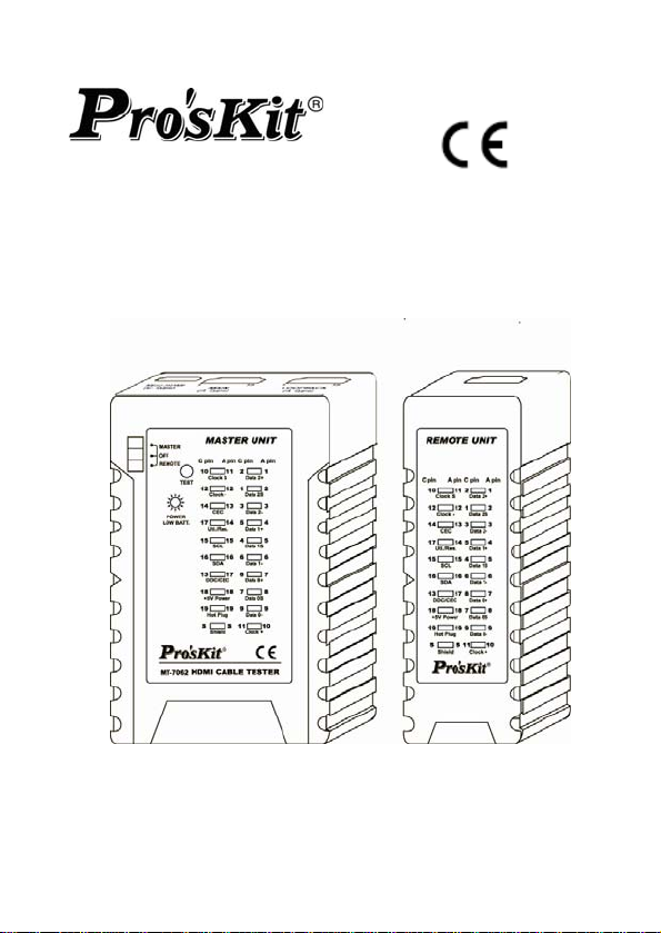
MT-7062 HDMI Cable Tester
User Manual
User’s Manual
1st Edition, 2013
©2013 Copyright by Prokit’s Industries Co., Ltd.
Page 2
DESCRIPTI
The Pro’sKit MT-7062 HDMI Cable Tester is designed for
professional HDMI installations. This portable device allows installers
to quickly test, troubleshoot, and verify HDMI (high definition
multimedia interface) cables. MT-7062 is designed to test wire circuit
state of HDMI cables with Type A & C connectors conforming to 1.0,
1.1, 1.2, 1.2a, 1.3, 1.3a, 1.3b, 1.3c, 1.4, 1.4a Category 1 and
Category 2 cables
Equipped with 3 test modes, Automatically fast/slow scan or manual
test for step by step, this tool can either test the conductors in
straight、short、open、crossover in all RGB conductors.
SAFETY INFORMATION
Safety is essential in the use and maintenance of Pro’sKit equipment.
This instruction manual and any markings on the tool provide
information for avoiding hazards and unsafe practices related to the
use of this tool. Observe all of the safety information provided.
Do not connect tester to a live circuit as it may damage the unit.
It is easy to damage this tester with charged HDMI lines.
Read all instructions in this manual before using this tester.
Do not drop or get the unit wet. Do not expose tester to extreme
Do not use this tester with its case open, or with parts removed.
Repairs and maintenance must only be carried out by qualified
Follow the recommendations of any Trade Organizations or
Remove the battery when the tester not in use for longer than a
Please use batteries according to the specification; otherwise it
ON
Warnings
Caution
Failure to do so may result in damage to the tester or injury to the
user.
humidity or direct sunlight.
Doing so may damage the tester and/or injure the user.
service personnel or qualified electricians/technicians who know
the dangers.
Regulatory Agencies whose scope encompasses the use of this
tester or injury to the user.
month. Chemical leakage from the battery could damage the
tester.
may result in damage to equipment.
1
Page 3

TENTS
CON
Your MT-7062 HDMI Cable Tester contains the following:
1. 1 x Master unit
2. 1 x Remote unit
3. 1 x Pouch bag.
4. Users’ Manual.
FEATURES:
The MT-7062 HDMI cable tester allows the fast and accurate
verification both HDMI type A and Type C cables, mapping continuity
and proper configuration and displays 19 pins and shield connection
status on both master and remote unit.
For HDMI cables Type A, C
Test all HDMI cables with Type A to A, A to C and C to C
connectors, especially for fragile, easily damaged HDMI patch
cord and in-wall HDMI cables.
Loopback function
Design with loopback function allows test HDMI type A to A, A to
C on master unit.
3 Test Modes
Fast continuity scans for testing all conductors’ status in a cable.
Slow continuity scans for testing all conductors’ status in a cable.
Manual test for step by step scan detecting of individual
conductors’ situation.
HDMI Cable Mapping
Automatically detect wiring on HDMI type A or type C condition in
straight、short、open、crossover in pin #1~#19 and Shield
conductor.
Troubleshooting
Quickly troubleshoot and verify HDTV installation and DIY
termination in the field.
SPECIFICATIONS:
Cables Tested:HDMI cables with Type A & C connectors
conforming to 1.0, 1.1, 1.2, 1.2a, 1.3, 1.3a, 1.3b, 1.3c, 1.4, 1.4a
Category 1 and Category 2 cables.
Support test (master unit and remote unit):19 pin-to-pin wire
map and shielding detection.
Test interface of Master unit:HDMI (type A) ×2 pcs, Mini HDMI
(type C) ×1 pcs.
2
Page 4
Test
Cable length:Under 50 meters.
Test Mode:Automatically fast scan、Automatically Slow scan、
Displays:19 LEDs and shield LED on both master and remote
Beeper indication.
Low battery indication:Under 6.0V
Power source:DC 9V(NEAD 1604/6F22)×1 (not included)
Dimension:Master unit:103×66×27,Remote unit:103×35×27
Weight:130g (not incuding battery)
Operating environment:32℉ to 104℉ (0℃ to 40℃)<80% RH
Storage environment:14℉ to 122℉ (-10℃ to +50℃)<70% RH
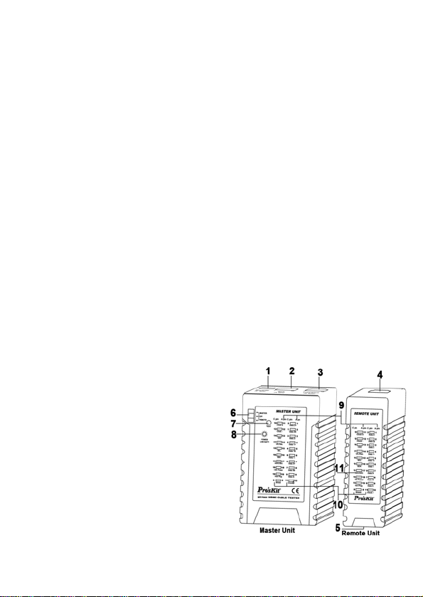
PRODUCT DIAGRAM
1. LOOPBACK:Mini-HDMI (C Type)
2. MAIN:HDMI (A Type)
3. LOOPBACK:HDMI (A Type)
4. Remote unit:H
5. Remote unit:Mini-HDMI (C
6. Switch:
7. TEST:Automatic fast/slow
8. Power and low battery
9. HDMI (A Type) Pin number.
10. Mini-HDMI (C Type) Pin
11. LED for indicating signal
interface of Remote unit:HDMI (type A) ×1pcs, Mini HDMI
(type C) ×1 pcs.
Manual test for step by step.
unit.
mm
This socket not only can be used on Master unit loopback test but
also can be used on Master unit Mini-HDMI (C Type) with Remote
unit Mini-HDMI (C Type) to perform scan test.
DMI (A Type)
Type)
MASTER/OFF/REMOTE
scan or manual test for step by
step.
indication.
number.
situation.
3
g 1
Fi
Page 5
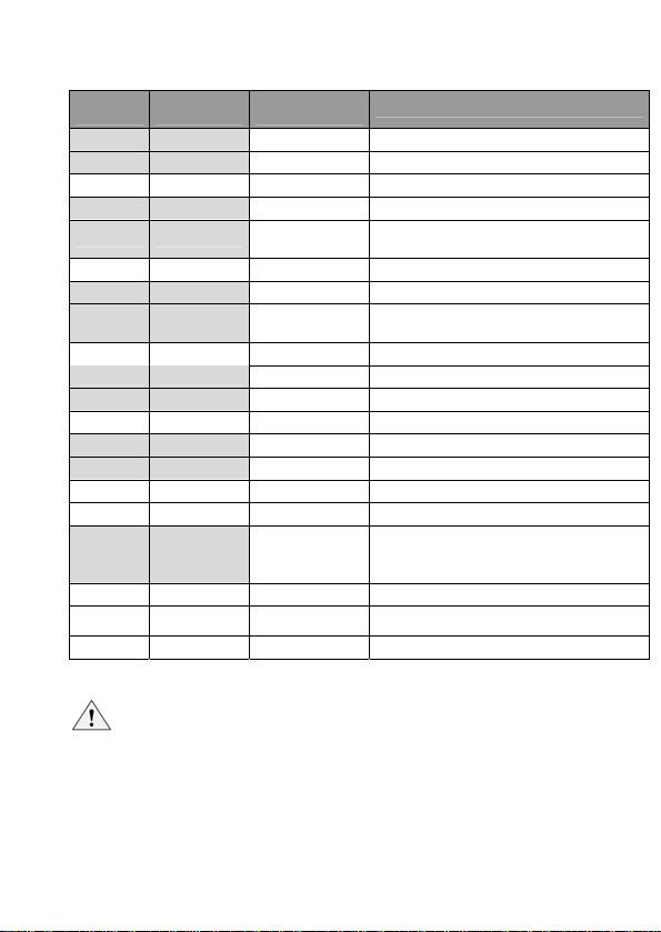
HDMI Ca
ble Wire / Pin And Signal Description:
HDMI
(A)Pin #
Mini-HDMI
(C) Pin #
1 2 Data 2﹢ TMDS Red Data Plus (Data 2 +)
2 1 Data 2S TMDS Red Data Shield (Data 2 Shield)
3 3 Data 2﹣ TMDS Red Data Minus (Data 2 –)
4 5 Data 1﹢ TMDS Green Data Plus (Data 1 +)
5 4 Data 1S
6 6 Data 1﹣ TMDS Green Data Minus (Data 1 –)
7 8 Data 0﹢ TMDS Blue Data Plus (Data 0+)
8 7 Data 0S
9 9 Data 0﹣ TMDS Blue Data Minus (Data 0 –)
10 11 Clock ﹢ TMDS Clock Plus (Clock +)
11 10 Clock S TMDS Clock Shield (Clock Shield)
12 12 Clock ﹣ TMDS Clock Minus (Clock –)
13 14 CEC Consumer Electronics Control
14 17 Uti./Res. Utility/Reserved
15 15 SCL Serial Clock (I2C)
16 16 SDA Serial Data (I2C)
17 13 DDC/CEC
18 18 +5V Power + 5V Power
19 19 Hot Plug Hot Plug Detect
S S Shield Shield
Pin
Assignment
Signal Description
TMDS Green Data Shield (Data 1
Shield)
TMDS Blue Data Shield (Data 0
Shield)
Data shield for the display data
channel and consumer electronics
control
OPERATION
Note
When all LEDs are lighted all LEDs will decrease brightness.
Master unit shorted pins LED will be brighter than others when
shorted 2 pins above that is correct.
Shield LED will light up after #1~19 LEDs light up in sequence
on any testing mode. If the HDMI cable has a shield, the
Shield LED will light up, if without shield the LED will be
unlighted.
4
Page 6

wer off:
Po
Slide upper left switch to “OFF”,”POWER” LED will go out and the
unit will no longer work when pushing the “TEST” button.
Master unit loop continuity scan testing function
Note
When performing master unit scan test, sequence of LEDs
light up as below.
LED#1 (Data 2﹢)→ LED#10 (Clock ﹢)→ LED#S (Shield)→
LED#11 (Clock S)。
※ Insert one of A type connector of cable to Master unit
LOOPBACK (A Type) socket and insert the other one to
Master unit MAIN (A Type) socket for test HDMI cable A type
to A type.
※ Insert A type connector of cable to Master unit LOOPBACK (A
Type) socket and insert C type connector of cable to Master
unit Mini-HDMI (C Type) for test HDMI cable A type to
Mini-HDMI (C Type).
1. Slide upper left switch to “MASTER” then “POWER” LED
lights up, Master unit #1~19 and “Shield” LEDs will all light
up with a long beep sound then all LEDs are off except
“POWER”LED for saving power and the unit is ready for
testing.
2. Push “TEST” button to perform master unit continuity scan
test, it will continually scan 1~19 pin and shield conductor,
Master unit #1~19 and Shield LEDs will light up in
sequence fast, finally master unit LED will indicate testing
result with sound as below. The testing result will keep 5
second then all LEDs are off except “POWER” LED for
saving power. Press “TEST” button again for test.
3. Master unit scan test result with beep sound as below.
Straight:With a long “beep” sound: Meaning 1~19pin
and S pin all straight connected. (Fig 2.)
5
Page 7
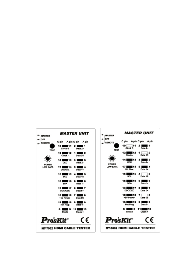
Open:with a short “beep” sound。No connected pins LED
are off. Example: Test HDMI (A Type) to HDMI (A Type)
cable that pin #2, #5, #8 and #11 are not connected , or
test HDMI (A Type) to Mini-HDMI (C Type) cable that pin
#1、#4、#7、#10 are not connected. (Fig 3.)
Short: With three short “beep” sound. Shorted pins LED
will light up at same time. Example: Test HDMI (A Type)
to HDMI (A T ype) cable that pin #4、#5、#6 are shorted or
test HDMI (A Type) to Mini-HDMI (C Type) cable that pin
#4、#5、#6 are shorted. (Fig 4.)
Crossover:With two short “beep” sound. Crossed pins
LED will light on at same time. Example: Test HDMI (A
Type) to HDMI (A Type) cable that pin #13 crossed with
pin #17 and pin #14 crossed with pin #19, or test HDMI A
Type) to Mini-HDMI (C Type) cable that pin #14 crossed
with pin #13 and pin #17 crossed with pin #19. (Fig 5.)
Fig 2. Straight Fig 3. Open
6
Page 8
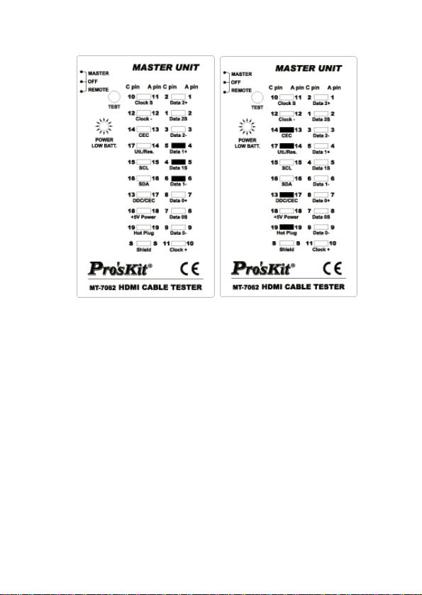
Fig 4. Short Fig 5. Crossover
Master unit with Remote unit automatic testing function
※ Insert one of A type connector of cable to Master unit MAIN (A
Type) socket and insert the other one to Remote unit A Type
connector for test HDMI cable A type to A type.
※ Insert A type connector to Master unit LOOPBACK (A Type)
and insert C type connector to Remote unit Mini-HDMI (C
Type) for test HDMI cable A type to Mini-HDMI (C Type).
※ Insert one of C type connectors of cable to Master unit
Mini-HDMI (C Type) socket and insert the other one to Remote
unite (C Type) socket for test HDMI cable Mini-HDMI (C Type)
to Mini-HDMI (C Type) socket.
1. Slide upper left switch to “REMOTE” then “POWER” LED
lights up. Master unit #1~19 and “Shield” LEDs will all light
up with a long beep sound then Master unit and Remote
unit both #1~19 and “Shield” LEDs will indicate tested
result. Testing result will keep 12 seconds then all of LED
are off except “POWER”LED for saving power.
7
Page 9

2. Press “ TEST” button then Master unit and Remote unit
both #1~19 and “Shield” LEDs will indicate tested result.
Testing result will keep 12 seconds then all LEDs are off
except “POWER”LED for saving power.
3. LED indicates test result as below:
Straight:Master unit and Remote unit both testing
pin #1~19 and “Shield” LEDs are all lighted up. (Fig
6.)
Open:Master unit and Remote unit both no
connected pins LEDs are off. (Fig 7.)
Short:Master unit testing short pin LEDs brighter
than others. Remote unit shorted pins LEDs are off.
(Fig 8.)
Crossover:It can’t be tested on this mode.
Master unit with Remote unit slow continuity scan testing
function:
1. Press “ TEST“ button during LED indicate automatic
testing result or Press twice “ TEST“ button before LED off
for perform automatic testing, it will continually scan
#1~#19 pin and shield conductor. Master unit and Remote
unit both #1~19 and Shield LEDs will light up in sequence
very slow and sustained repeated automatic scan
2. LED indicate testing result as below:
Straight:Master unit and Remote unit both testing
pins #1~19 and Shield LEDs are all lighted up in
sequence. (Fig 6.)
Open: Master unit and Remote unit both LEDs are
off when scan to no connected pins, others LEDs are
all lighted up in sequence. Example : Test HDMI (A
Type) to HDMI (A Type) cable that pin #2、#5、#8、
#11 are not connected, or test HDMI (A Type) to
Mini-HDMI (C Type) cable that pin #1、#4、#7、#10 are
not connected, or test Mini-HDMI (C Type) to
Mini-HDMI (C Type) cable that pin #1、#4、#7、#10 are
not connected. (Fig 7.)
8
Page 10

Short:Master u
Remote unit LED off when scan to shorted pins,
Master unit and Remote unit both LED are all lighted
up in sequence,
HDMI (A T ype) cable that pin #4、#5、#6 are shorted,
or teat HDMI (A Type) to Mini-HDMI (C Type) cable
that pin #4、#5、#6 are shorted, or test Mini-HDMI (C
Type) to Mini-HDMI (C Type) cable that pin #4、#5、
#6 are shorted. (Fig 8.)
Crossover:Master unit LEDs light up in sequence
and Remote unit LEDs light up sequence by crossed
Example : test HDMI (A Type) to HDMI (A
pins,
Type) cable that pin #13 with pin#17 are crossed and
pin #14 with pin #19 are crossed, or test HDMI (A
Type) to Mini-HDMI (C Type) cable pin #13 with pin
#13 and pin #14 with pin #19 are crossed, or test
Mini-HDMI (C Type) to Mini-HDMI (C Type) cable pin
#14 with pin #13 are crossed and pin #17 crossed
with #19 are crossed. (Fig 9.)
nit LED brighter than others and
Example : Test HDMI (A Type) to
Fig 6. Straight
9
Page 11

Fig 7. Open
Fig 8. Short
10
Page 12

Fig 9. Crossover
Master unit with Remote unit fast continuity scan testing
function:
1. Press “ TEST” button during the slow continuity scan testing, or
press three times“ TEST” button after the automatic testing
LEDs are off:It will fast scan pin 1~19pin and Shield,Master unit
and Remote unit both #1~19 and Shield LEDs will light up in
sequence fast and sustained repeated automatic scan.
2. The test result please refer to the slow continuity scan testing
function. (Fig 6. ~ Fig 9.)
Master unit with Remote unit manual scan testing function:
1. Press “ TEST” button for three seconds until pin #1 LED lights
up, pin #2 ~ 19pin+Shield LEDs light up step by step
sequentially after pressing “ TEST” button and sustained
repeating.
2. The test result please refer to the slow continuity scan testing
function. (Fig 6. ~ Fig 9.)
3. Press “ TEST” button three seconds again then go back to
automatic testing mode.
11
Page 13

B
ATTERY LIFE AND REPLACEMENT:
Caution
To avoid unreliable test results, replace the battery as soon as
the low battery indication appears.
To avoid possible electric shock or personal injury, turn off the
Battery Status:When ”POWER/LOW BATT.” LED is flashing on the
master unit, it means the battery voltage is under 6.0V which couldn’t
power the device on. Please replace the battery as the following
step:
1. Turn off the master unit and disconnect all test leads before
2. Properly replace the battery into the battery case.
3. Use only a DC 9V(NEAD 1604/6F22) battery.
HDMI® is a registered trademark of HDMI Licensing, LLC.
Warnings
master unit and disconnect all test leads before replacing the
battery.
replacing the battery.
MT-7062 HDMI測試器使用手冊
產品概述
Pro’sKit MT-7062 HDMI測試器,是為專業的HDMI安裝而設計。這種
方便攜帶的測試器,可以提供安裝工程師快速測試、檢修、查證HDMI(高
清晰多媒體接口)電纜線。MT-7062是用於測試HDMI電纜線電路狀態,
適用於具有A和C接口,符合 1.0, 1.1, 1.2, 1.2a, 1.3, 1.3a, 1.3b, 1.3c,
1.4, 1.4a 第1類和第2類的HDMI電纜線。配備3種測試模式:自動快速
/慢速掃描和手動單步測試。這測試器可以測試HDMI電纜線內RGB訊
號芯線導體的直通、短路、斷路、交叉…等狀態。
安全須知
在使用和維護Pro
測試器上提供的訊息,是為避免危險和不安全的作法,使用這測試器。
請遵守所有安全資訊規範。
’sKit的設備,安全是重要的!本說明書和任何標示在
12
Page 14

警告
不要連接這測試器在具有活電的電路上,因為它有可能損害這
設備。
在充電的HDMI電纜線上,使用本測試器,容易造成測試器損
害。
注意
在操作測試器前,請詳閱本說明書。如未遵守相關規定,可導
致測試器損害或危及使用者。
不要跌落或浸濕這測試器。不要讓這測試器暴露在潮濕的環境
中或讓烈日直接照射。
不要試圖打開測試器外殼或移除零件,這樣做可能導致測試器
損壞和危及使用者。
維修和保養,必須交由熟知危險的專業維修人員或具備資格的
電氣工程師/技術員進行。
遵循任何貿易組織或監管機構的建議,其範圍包含使用這測試
器或對於使用者的傷害。
當長時間或超過一個月不使用本測試器,應將電池取出,避免
電池化學液滲漏,損壞本測試器。
請使用同規格的電池,否則可能損壞本設備。
包裝內容:
你的MT-7062 HDMI 測試器,包裝內容如下:
主機 1台.
遠端器 1個.
攜存袋 1個.
使用手冊 1本.
特點:
這MT-7062 HDMI測試器,可以快速和準確的查證A型和C型等2種接口
的HDMI電纜線,對應針腳的連通、正確的線序配置,並將19針腳和屏
蔽連接狀態,顯示在主機和遠端器上。
測試A型和C型接口的HDMI電纜線
可以測試具有A對A、A對C、C對C接口的HDMI電纜線,由其是脆弱、
易損壞的HDMI連接線和在牆內的HDMI電纜線。
13
Page 15

主機
自我迴路測試
具有主機自我迴路測試的設計,只有主機.不必遠端器,就可以測試A
對A、A對C接口的HDMI電纜線。
3種測試模式
具有自動快速掃描功能,可以測試電纜線中,所有芯線導體連
通狀態。
具有自動慢速掃描功能,可以測試電纜線中,所有芯線導體連
通狀態。
具有手動測試功能,可以單步間歇的偵測電纜線中,個別芯線
導體的故障狀態。
HDMI電纜線連通測試
自動檢測HDMI電纜線內,19條訊號和屏蔽芯線導體的直通、短路、斷
路、交叉…等狀態。
故障檢修
適合快速檢修和查證HDTV安裝,和DIY製作HDMI連接線。
產品規格:
電纜測試:適用於具有A和C接口,符合 1.0, 1.1, 1.2, 1.2a, 1.3,
1.3a, 1.3b, 1.3c, 1.4, 1.4a 第1類和第2類的HDMI電纜線。
支持測試 (主接和遠端器):適用於19針腳的腳對腳線序和屏蔽
測試。
主機測試接口:具有2個HDMI (type A)接口、1個Mini HDMI
(type C)接口。
遠端器測試接口:具有1個HDMI (type A)接口、1個Mini HDMI
(type C)接口。
電纜線長度︰小於50米。
測試模式:自動快速掃描、慢速掃描、手動單步測試等3種模式。
顯示:主機和遠端器上,均具有19個lLED和1個屏蔽LED。
電池低電壓指示:低於6.0V時。
電源:1個DC 9V(NEAD 1604/6F22)電池。
外觀
重量:130克 (不含電池)
操作環境:32℉ 至 104℉ (0℃ 至 40℃) <80% RH
儲存環境:14℉ 至 122℉ (-10℃ 至 +50℃) <70% RH
尺寸:主機:103×66×27 mm、遠端器:103×35×27 mm。
14
Page 16

產品外觀圖:
(
–
)
1. 主機迴路接口:
Mini-HDMI (C Type)
(這個接口,當與遠端器搭
配測試Mini-HDMI (C
Type)對Mini-HDMI (C
Type)線時,也做為主機接
口。)
2. 主機主要接口:HDMI (A
Type)
3. 主機迴路接口:HDMI (A
Type)
4. 遠端器接口:HDMI (A
Type)
5. 遠端器接
口:Mini-HDMI (C Type)
(圖 1.) 產品
外觀圖
6. 開關:主機自我迴路測試 / 關機 / 遠
端測試
7. 測試鍵:自動快速/慢速掃描和手動單步測試
8. 電源和電池低壓指示燈
9. HDMI (A Type)針腳序號
10. Mini-HDMI (C Type)針腳序號
11. 信號說明與指示燈
HDMI 線芯/腳位及信號說明:
HDMI (A)
針腳序號
1 2
2 1 Data 2S
3 3
4 5
5 4 Data 1S
6 6
Mini-HDMI
(C) 針腳序號
針腳訊號 信號說明
Data 2﹢
Data 2﹣
Data 1﹢
Data 1﹣
TMDS Red Data Plus
(Data 2 +)
TMDS Red Data Shield
(Data 2 Shield)
TMDS Red Data Minus
(Data 2 –)
TMDS Green Data Plus
(Data 1 +)
TMDS Green Data Shield
(Data 1 Shield)
TMDS Green Data Minus
Data 1
15
Page 17

7 8
8 7 Data 0S
9 9
10 11
11 10 Clock S
12 12
13 14 CEC
14 17 Uti./Res. Utility/Reserved
15 15 SCL Serial Clock (I2C)
16 16 SDA Serial Data (I2C)
17 13 DDC/CEC
18 18 +5V Power + 5V Power
19 19 Hot Plug Hot Plug Detect
S S Shield Shield
Data 0﹢
Data 0﹣
Clock ﹢
Clock ﹣
TMDS Blue Data Plus
(Data 0+)
TMDS Blue Data Shield
(Data 0 Shield)
TMDS Blue Data Minus
(Data 0 –)
TMDS Clock Plus (Clock +)
TMDS Clock Shield (Clock
Shield)
TMDS Clock Minus
(Clock –)
Consumer Electronics
Control
Data shield for the display
data channel and
consumer electronics
control
操作使用:
注意
當主機或遠端器的燈號全部亮起時,燈號會有較暗的情況,屬於
正常現象。
當短路超過2 pin以上時,主機短路的pin燈號會比其他燈號更亮,
屬於正常現象。
任何一種測試模式下,當燈號掃描#1~#19後,緊接著都會掃描S
燈。當S燈亮起,代表被測的HDMI電纜線具有屏蔽功能。如果S
燈不亮,代表被測的HDMI電纜線是屬於非屏蔽線。
關機:
主機左上角開關,撥到 OFF檔位時,POWER 燈不亮,按下 TEST 鍵,
不工作。
16
Page 18

機自我迴路連續快速掃瞄測試:
主
注意
當「主機自我迴路連續快速掃描測試」結果顯示時,燈號掃描
順序是: #1 (Data 2﹢)→ #10 (Clock ﹢)→ #S (Shield)→ #11
(Clock S)。
※ 測試 HDMI (A Type)對 HDMI (A Type)的線時:將線插入主機
LOOPBACK (A Type)接口和 MAIN (A Type)接口。
※ 測試 HDMI (A T ype)對 Mini-HDMI (C Type)的線時:將線插入主
機 LOOPBACK (A Type)接口和 Mini-HDMI (C Type)接口。
1. 主機左上角開關,撥到 MASTER檔位時,POWER 燈號與主機的
1~19pin+Shield 燈號全部顯示,並“滴”一 聲 長 音,持 續 2 秒鐘後,
主機的 pin 燈號會自動熄滅,進入待測的省電模式,只有 POWER
燈號持續亮。
2. 按一下 TEST鍵是:「主機自我迴路連續快速掃描測試」:快速
自動掃描 1~19pin+Shield,主機的 1~19pin+Shield 燈號,逐一
快速顯示一個週期後,主機的 pin 燈號顯示測試結果,並聲音提
示(如下)。測試結果持續 5 秒鐘後,主機的 pin燈號會自動熄滅,
進入省電模式,只有 POWER 燈號持續亮。再按一下 TEST 鍵,
反覆上述一次…
3. 「主機自我迴路連續快速掃描測試」時,結果顯示:
直通:“滴”一聲長音。1~19~S 的直通 pin 燈號會同時點亮。(圖 2.)
斷路:“滴”一聲短音。斷路的 pin 燈號不亮。如 HDMI (A T ype)對
HDMI (A Type)線的#2、#5、#8、#11斷路或HDMI (A Type)對
Mini-HDMI (C Type) 線的#1、#4、#7、#10 斷路。(圖 3.)
短路:“滴滴滴”三聲短音。短路的 pin燈號會同時點亮。如 HDMI
(A T y pe)對 HDMI (A Type)線的#4、#5、#6 短路或 HDMI (A T ype)
對 Mini-HDMI (C Type) 線的#4、#5、#6 短路。(圖 4.)
交叉:“滴滴”二聲短音。交叉的 pin燈號會同時點亮。如 HDMI (A
Type)對 HDMI (A Type)線的#13 和#17、#14 和#19 交叉或 HDMI
(A Type)對 Mini-HDMI (C Type) 線的#14和#13、#17 和#19 交
叉。(圖 5.)
17
Page 19

圖 2. 導通 圖 3. 斷路
圖 4. 短路 圖 5. 交叉
18
Page 20

端自動測試:
主機+遠
※ 測試HDMI (A Type)對HDMI (A Type)的線時:將線插入主機
MAIN (A Type)接口和遠端器HDMI (A Type)接口。
※ 測試HDMI (A Type)對Mini-HDMI ( C Type)的線時:將線插入主
機MAIN (A Type)接口和遠端器Mini-HDMI (C Type)接口。
※ 測試Mini-HDMI (C Type)對Mini-HDMI (C Type)的線時:將線插
入主機Mini-HDMI (C Type)接口和遠端器Mini-HDMI (C Type)
接口。
1. 主機左上角開關,撥到REMOTE檔位時,POWER燈號點
亮,主機1~19pin+Shield燈號先全部顯示,並“滴”一聲長音
後,接續主機與遠端器的兩組1~19pin+Shield燈號顯示測試
結果,測試結果持續12秒鐘,主機與遠端器的兩組pin燈號會
自動熄滅,進入省電模式,只有POWER燈號持續亮。
2. 按一下TEST鍵,主機與遠端器的兩組1~19pin+Shield燈號
會再顯示測試結果,測試結果持續12秒鐘,依此反覆…
3. 「主機+遠端自動測試」結果顯示:
直通:主機和遠端器直通的 pin燈號都亮。(圖 6.)
斷路:主機和遠端器斷路的 pin燈號都不亮。(圖
短路
交叉:此模式無法測試。
主機+遠端慢速連續掃描測試:
1. 上述pin燈號未熄滅前,再按一下TEST鍵(或是「主機+遠端自
動測試」結果顯示的pin燈號熄滅後,連按二下TEST鍵)是:「主
機+遠端慢速連續掃描測試」:慢速自動掃描1~19pin+
Shield,並持續反覆慢速自動掃描。
2. 「主機+遠端慢速連續掃描測試」,結果顯示:主機與遠端器
的pin燈號,會從1~19~S依順序點亮:
直通:主機和遠端器直通的 pin 燈號從 1~19~S 依順序點
亮。(圖 6.)
:主機短路的 pin 燈號會比其他燈號更亮,遠端
器短路的 pin 燈號不亮。(圖 8.)
7.)
19
Page 21

:主機和遠端器斷路對應的 pin 燈號都不亮,其它 pin
斷路
燈號從 1~19~S 依順序點亮。如 HDMI (A Type)對 HDMI (A
Type)線的#2、#5、#8、#11 斷路或 HDMI (A Type)對
Mini-HDMI (C Type)線的#1、#4、#7、#10斷路或 Mini-HDMI
(C Type)對 Mini-HDMI (C Type)線的#1、#4、#7、#10 斷路。
(圖 7.)
短路:主機短路的 pin 燈號,會比其他 pin 燈號更亮,遠
端器短路的 pin 燈號不亮,主機和遠端器其它 pin 燈號從
1~19~S 依順序點亮。如 HDMI (A Type)對 HDMI (A Type)
線的#4、#5、#6 短路或HDMI (A Type)對Mini-HDMI (C Type)
線的#4、#5、#6 短路或 Mini-HDMI (C Type)對 Mini-HDMI (C
Type)線的#4、#5、#6 短路。(圖 8.)
交叉:主機的pin燈號從1~19~S依順序點亮,遠端器的pin
燈號依實際交叉順序點亮。如HDMI (A Type)對HDMI (A
Type)線的#13和#17、#14和#19交叉或HDMI (A Type)對
Mini-HDMI (C Type) 線的#13和#13、#14和#19交叉或
Mini-HDMI (C Type)對Mini-HDMI (C Type)線的#14和#13、
#17和#19交叉。(圖 9.)
圖 6. 導通
20
Page 22

圖 7. 斷路
圖 8. 短路
21
Page 23

圖 9. 交叉
主機+遠端快速連續掃描測試:
1. 遠端慢速自動掃描進行時,再按一下TEST鍵(或是遠端快速
結果顯示的pin燈號熄滅後,連按三下TEST鍵)是:「主機+
遠端快速連續掃描測試」:快速自動掃描1~19pin+Shield,
並持續反覆快速自動掃描。
2. 「主機+遠端快速連續掃描測試」,結果顯示:主機與遠端器
的pin燈號,會從1~19~S依順序點亮:燈號顯示與「主機+
遠端慢速連續掃描測試」相同。(圖 6.~ 圖 9.)
主機+遠端手動單步測試:
1. 長按3秒是:「主機+遠端手動單步測試」:按一下測試 1pin…
依此類推1~19pin+Shield,並持續反覆手動測試。
2. 「主機+遠端手動單步測試」,結 果 顯示:每 按 TEST鍵一下,
主機與遠端器會顯示1個pin燈號,並依序從1~19~S逐一點
亮:燈號顯示與「主機+遠端慢速連續掃描測試」相同。(圖 6.~
圖 9.)
3. 再長按3秒,即回到「主機+遠端自動測試」的模式。
22
Page 24

電池壽命與更換:
小心
為避免資料測試不可靠,一但出現電池低電壓指示時,請立即
更換新電池。.
警告
更換電池前,為避免觸電或人身傷害,請關閉主機,並斷開所
有測試導線。
電池狀態:當主機上的”POWER/LOW BATT.”的LED燈閃爍時,代表
電池的電壓已低於6.0V。請依照下列指示,更換電池︰
1. 更換電池前,請關閉主機,並斷開所有測試導線。
2. 打開主機背面的電池蓋,並正確的裝上新電池。
3. 僅可以使用1個DC 9V(NEAD 1604/6F22)的電池。
HDMI® 註冊商標屬於 HDMI Licensing, LLC.所有
23
 Loading...