

Page 1
MINI LAN CABLE TESTER
MT-7058
User’s manual
INTRODUCTION
The mini LAN cable tester complies with CE
safety standard, compact size and lightweight
design for easy detection of good connections,
opens, crossed wires & split pairs by only one
touch testing. Traces wires with tone. Remote
lights allow one person operation. Additional
non-contact voltage detection provides user
safety. Ideal for testing installed cables or
patch cords with RJ-45, RJ-11, RJ12 and
BNC connectors.
SAFETY RULES& WARNINGS
Read all instruction in this manual before
1.
using this tester. Failure to do so may result
in damage to the tester or injury to the user.
2. Do not use this tester with its case open, or
with parts removed. Doing so may damage
the tester and/or injure the user.
3. When using this tester in schools and
workshops, responsible teachers or skilled
personnel must control the usage of this
tester. Failure to observe this precaution
may result in damage to the tester or injury
to the user.
4. Follow the recommendations of any Trade
Organizations or Regulatory Agencies
whose scope encompasses the use of this
tester failure to do so may result in damage
to the tester or injury to the user.
5.
Repairs and maintenance must only be
carried out by qualified service personnel or
qualified electricians/technicians who know
the dangers of.
6. Do not apply voltage or current to any of the
tester’s connectors. Doing so may damage
the tester and /or injury the user.
7. Remove the battery when the tester not in
use for longer than a month. Chemical
leakage from the battery could damage the
tester.
PRODUCT FEATURES
1. Complies with CE safety standard
2. Automatically detect good connections,
opens, crossed wires & split pairs
3. Simple one button test
4. LEDs indicate connections and faults
5. Tests shielded (STP)or unshielded(UTP)
LAN cables
6. BNC cable indicator
7. Non-contact voltage detection for user
safety.
8. Long cable test more than 300 meters
9. Low power consumption with auto power
off function to preserve battery.
SPECIFICATIONS
1. Cables Tested: UTP and STP LAN cables
Terminated in RJ-45 male connectors. (EIA/
TIA 568)RJ-11, RJ-12 cables with male
connectors, 2 to 6 connectors installed.
BNC cables with male connectors.
2. Faults Indicated: No Connection, Short,
Straight, and Crossover.
3. Low Battery Indicator: LED lights different
colors to indicate low battery
4. NCV detection for AC60V~240V 60Hz
5. Case Dimensions:100*60*24.5mm(LxWxH)
6. Weight:120g (without battery)
7. Battery: 12V battery. AE23
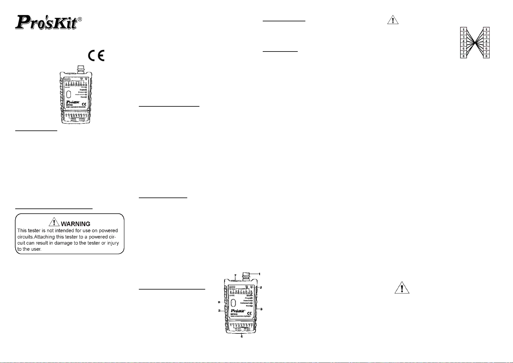
PRODUCT DESCRIPTION
1. BNC connector
2. Non-contact voltage
indicator
3. Power/sound on/off switch
4. RJ-45/RJ-11/12 connector
5. Auto / manual NCV switch
6. One touch push button
7. RJ-45/RJ-11/12 connector
ACCESSORIES
Female
Instruction Manual If RJ45 or RJ11/12 all wires
Pouch
OPERATION
1. The MAIN and REMOTE unit:
The Mini LAN Cable Tester consists of a
main unit and a remote unit. The remote
unit stores conveniently on the bottom of
the main unit. It can be removed or
replaced by sliding it from left to right or
right to left respectively.
2. Performing the test:
Once the remote and main units are
attached to the ends of the subject cable,
as described in 3.2 and 3.3, testing may
begin, simply press and release the test
button on the main unit, observe the LED
indicators, and note the beeping sound that
comes from the main unit.
3. Interpreting the results:
3.1 Power LED:
3.2 No connection LED
3.3 Straight/Crossover LED
connection. If some of the LEDs do not light
up, but others light up, and the straight LED
also lights up, it means the cable is open. If
some of the LEDs light up inconsistently,
and the straight LED also lights up, it
means the cable may be misconnected.
Please check in turn of lighted LED of
remote unit to identify which wires are
misconnected or change left side switch to
“Step” become manual function to check
the misconnection status step by step.
BNC Terminator
Bag
The power LED should lights up
whenever the test button is pressed and
released. If the power LED turns red,
replace the battery.
If the remote is not connected to the
main unit with a cable, or the cable has
no intake conductors, the no connection
LED will light up and the beeper will
sound for 4 times.
When all of the appropriate numbered
LEDs light up, the straight or
LED also lights up, and the beeper
sounds for 4 times with crossover.. the
beeper sounds for 3 times with straight it
means the cable is all correct
crossover
are wrong order that
Straight LED will light
1 to 8, 2 to 7 and so on.
Note:
RJ-1
1/12 cables may have 2 conductors, 4
conductors, or 6 conductors. When testing 2
conductor cables, LED 4 ~ 5 must light up, for
4 conductor cables, LED 3~ 6 must light up
and for 6 conductor cables, LED 2~7 must
light up, and “STRAIGHT” LED also lights up.
The numbered LEDs do not indicate a good
connection exists; only shows connection
exists. If “Short” LED lights up during test, it
means the shorted was found in the cable.
3
.4 Short LED
If 3 & 4 LEDs lights up, and all other
LEDs do not light up, the cable is
shorted; the “short” LED will light up.
3.5 Crossover LED
Numbered 1~8 LEDs will light up, and
“Crossover” LED also lights up. Means
wires are crossover or wire crossed.
4. BNC testing:
Numbered LEDs will light up during
scanning, after scanning; both LEDs of
BNC on the main unit and the BNC receiver
will light up. If the BNC cable is short, only
the LED of BNC on the main unit lights up;
if the BNC cable is open, both LEDs of BNC
on the main unit and the receiver won’t light
and “no connection” LED will light up..
5.
Non-contact Voltage Detection:
Set the left side switch to the NCV position
and push the test button, As the detachable
antenna is located at the right top of the
tester, close to right top of the tester to the
live wires, the LEDs of NCV will light with
sound.
When the wire multiple faults, test results
show is in accordance with the host panel
"test results show" the lights from the top
down order, namely: Shot → Straight →
Crossover → No Connection!
e put the tester as close as
Pleas
possible to surface of tested
source for optima testing result.
Page 2
迷你網路測試器
MT-7058
一、 產品介紹:
MT-7058 是一款集多種線路測試功能及非
接觸電壓測量於一體的多功能纜線測試
器,可測試的線材種類 RJ-45、RJ-11、
RJ-12、BNC。 只需一按開關,所測試線
材狀況一目了然。 線材的斷路、短路、交
錯都一一顯示在主機面板上。
二、安全注意事項:
注意:此測試器不能用於測試帶有電壓之
活線,若將活線接於此測試器,可
能會造成測試器損壞。
** 使用前請細詳閱讀使用說明書,錯誤使
用可能造成測試器損壞。
** 使用時請勿將機殼打開使用或自行更
換內部零件,以免成測試器損壞。
三、產品特色:
雙功能指示:快速結果測試(斷路.交
叉.直通.短路) 與Pin to Pin 掃描測試
(1-8 LEDs)
網路.電話.BNC 3 合 1:可測試 RJ45
(8P8C)網路線、RJ11/12 (4P/2C.
6P/4C. 6P/6C)電話線、BNC 線與屏
蔽指示
聲光雙顯示:具有 LED 燈號與音頻嗶
聲的聲光雙指示功能、電池低電壓指
示、防誤測迴路保護電路
免接觸驗電:具有免接觸驗電功能,
確保網路架設作業的安全,並通過CE
安規認證
測試距離更遠:採用 12V(AE23)電
池,測試距離超過 300 米
攜帶方便:輕巧迷你的近遠端結合設
計,
附 BNC 終端電阻. 攜存袋,外出
作業更方便
四、產品規格:
1. 測試線材/接頭:UTP / STP / RJ-11/
RJ-12 / RJ45 / BNC
2. 自動 (AUTO)及手動 (STEP)切換掃
描檢測跳接正確性、短路、斷路及芯
線排列順序等功能
3. 非接觸電壓 AC60V~240V 60Hz 感
應測試(NCV)
4. BNC 接頭同軸電纜連接、斷路、短
路測試
5. 自動待機功能
6. 低電壓 LED 燈色指示
7. 尺寸:100*60*24.5mm (L x W x H)
8. 重量:120 克 (不含電池)
9. 適用電源:12V 電池 AE23
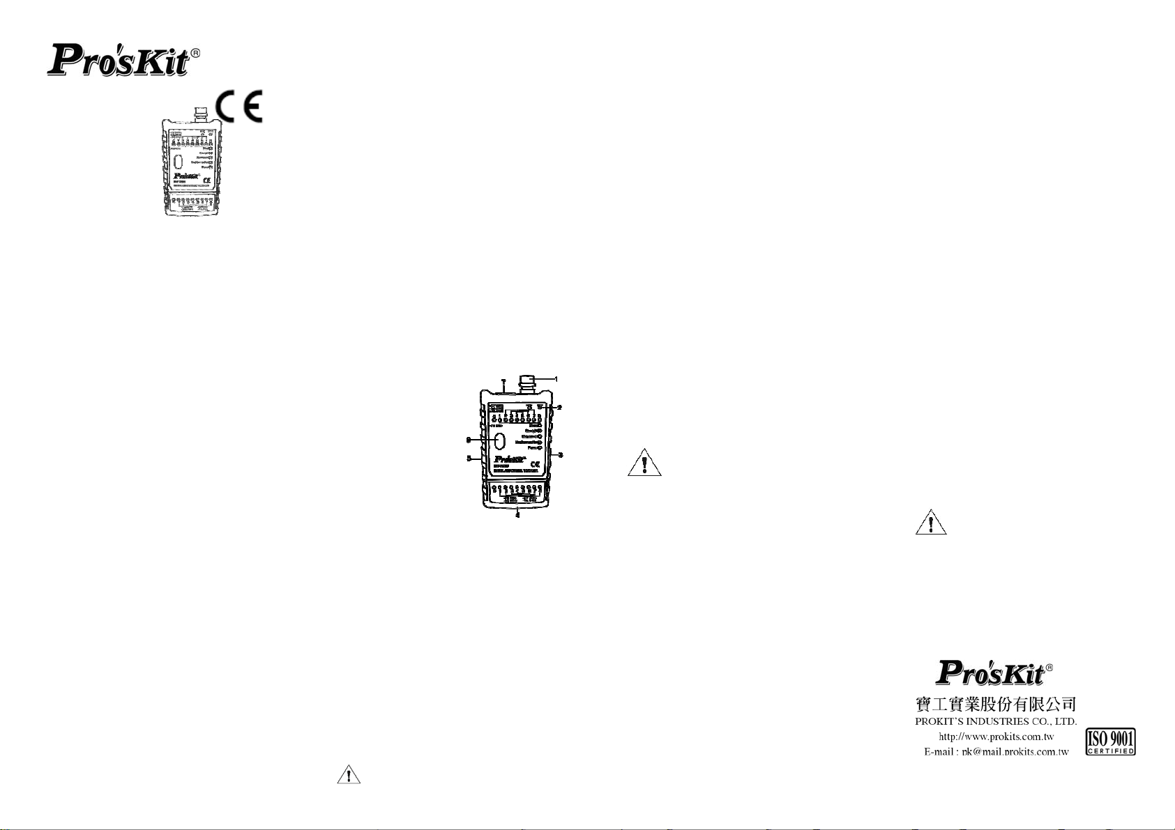
五、本體介紹︰
1. BNC 接頭
2. 免接觸驗電顯示
3. 電源/聲音開關
4. RJ-45/11/12 接頭
5. 自動/手動/免接觸
驗電開關
6. 測試按鈕
7. RJ-45/11/12 接
頭
六、配件:
1. BNC 母端接
2. 使用說明書
3. 收納袋
4. 12V (AE23)電池
七、顯示面板及 LED 燈功能介紹:
(1) “S"燈號:表示遮罩線
(2) “1 -8"燈號:表示對應的線路。
(3) “SHORT”燈號:表示線材有短路。
(4) “STRAIGHT"燈號:表示受測試的
線材連接是正確的或是代表一條扁
平的直通線。
RJ45 (8P8C)網路線和 RJ11/12
頭
(4P/2C. 6P/4C. 6P/6C)電話線兩端
的順序全反向時(即一線材端是 1~
8,另一端是 8~1 )測試結果為
“STRAIGHT"燈亮起, 蜂鳴器響 3
聲。此類,請結合主測試器和遠端測
試器判斷線材的情況。
(5) “CROSSOVER"燈號:表示受測試
的線材連接有交錯的問題或是代表
一條交叉的對絞線。
(6) “NO CONNECTION"燈號:表示沒
有相通的線,或是接頭沒有插好,有
可能是接觸不良。
(7) “POWER"燈號:按下測試鍵後亮綠
燈:表示本測試器的電源正常可正常
使用。亮紅燈:表示本測試器的電源
不足,應及時更換電池,以免對測試
結果產生影響。
(8) “NCV "燈號︰表示接觸電線存在
電壓
(9) “BNC"燈號︰同軸電纜導通判斷
八、3 種線材及 NCV 的測試方法
1. 測試 RJ45:
主測試器的測試結果皆需搭
配遠端接收器亮燈順序來判
斷線路正確性
把所需測試線插入主測試器和遠端測
試器,按
"燈亮,而上方對應的 8 顆 LED 燈亮
起順序一致時(如果是 STP 線則"S
"燈也會同時亮),表示這條線是連接
正確的線路。
如果"STRAIGHT"或
“CROSSOVER"燈亮,而主測試器和
遠端測試器燈號亮起的順序不一致就
表示有交錯或順序相反。此時只要查
看遠端接收器燈號亮起的順序即可得
知是哪幾條線錯接。
將側面的滑動開關切換至”STEP”手動
測試功能,逐一查看主測試器及接收
器 1-8 燈號顯示狀態。
如果"SHORT"燈亮,表示有短路,
一下開關主機"STRAIGHT
同時短路的路線與所對應的 LED 燈也
同時亮。
如果"STRAIGHT"燈亮,而 LED 燈
有幾顆不亮,表示對應的路線有斷路。
如果"CROSSOVER"燈亮,就表示
這條線是交叉線或錯接。.
2. 測試 RJ-11/12:
如果 6 芯電話線則 LED 亮“2-7",4
芯電話線亮“3-6",2 芯電話線“4-5”,
同時“STRAIGHT"燈也亮。
3. 測試 BNC 同軸電纜:
插入BNC測試座, 配合BNC母端接頭,
按下測試鍵, 掃描後若
態, 則“BNC"指示及母端接頭燈亮。
若電纜線開路, 則“NO
CONNECTION"指示燈亮. “BNC”指
示燈及母端接頭燈不亮, 若電纜線短
路, 則“BNC”指示燈亮, 母端接頭燈
不亮
4. NCV 測試:
將左側撥
TEST 鍵,並將本體右測頂端靠近被測
體,當交流電壓高於 60V 低於240V
時,“NCV"指示 LED 長亮並有響聲警
示。
果顯示」的優先排序,是依照主機面板上
「測試結果顯示」的燈號由上而下的順
序,即:Shot→Straight→Crossover→No
Connection!
©2013 Prokit’s Industries Co., LTD. All rights reserved 2013002( T)
動開關推到 NCV 檔位,按下
為提高測試靈敏度,請貼近待
測電源表面。
當線材多重故障時,「測試結
電纜線導通狀
 Loading...