

Page 1
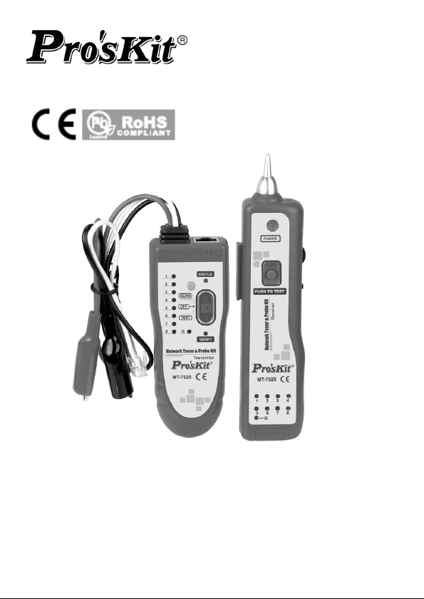
MT-7025 Network Tone & Probe Kit
User’s Manual
1st Edition, 2013
©2013 Copyright by Prokit’s Industries Co., Ltd.
Page 2

Thank you for buying PRO’SKIT MT-7025 Network Tone & Probe
Kit. Please read this instruction carefully before using the product.
Contents
1. Overall description
2. Feature
3. Specification
4. Packing list
5. Safety instructions
6. MT-7025 transmitter instructions
7. MT-7025 receiver instructions
8. Operated instructions
Wire map testing
Wire finding
Telecom cable open/ short testing
Telephone line polarity test
LED illumination
Earphone
9. Power source
10. Trouble Shooting.
1.Overall description
MT-7025 is a multifunction cable tester. It is a tester that combines
wire tracking, wire finding, cable mapping, and telephone line
polarity test. It can find the target wire in numerous messy wires,
and one doesn’t need to unplug the network cable or turn off the
switching equipment when finding wires. Signal transmission
distance over 2 kilometers. It can be applied on
telecommunications network installation and maintenance.
Compact sizes for carrying convenience, multifunction and easy to
operated, it is a competent tester.
1
Page 3

2.Feature
Multifrequency signal features strong anti - int
ability
Signal transmission distance up to 2 kilometers suitable for
long distance cable finding
Connected to Ethernet with signal voltage and transmit
signal directly, the receiver side can find the wire easily
Connected to switching equipment of Ethernet with signal
voltage for checking cable situation without turn off the
telecom switching equipment
Plug in RJ11 telecom cable for signal transmission and find
wire by receiver, suitable for telecommunication wiring
Check the polarity of telephone line by the Alligator
connector of transmitter
Two different signal frequencies for cable finding
Comes with RJ45,RJ11 cable,alligator connector cable,
RJ45 patch cord and ports to meet different applications
RJ45 connector for wire mapping test and cable status
detection (straight, short, no connection, cross wire) ideal for
UTP/STP/SFTP cat.5 cat.5e cat.6 and cat.3 cable.
Volume adjustment according to environment situation.
With earphone enable to work in noisy environment.
LED Illuminate function allowing work in dark areas.
erference
3.Specification
Transmitter
Tone frequency 1kHz
Max. distance of
transmission
Max. distance of cable map 300m
Max. working current ≦45mA
Tone mode ONE/TWO-note tone
Compatible connectors
2km
RJ45(8 pin)、RJ11(6P/2C)、
Alligator clips
2
Page 4
Transmitter
Continuity test Yes
Max. signal voltage 8Vp-p
Function selection 3 Position mode switch
Cable map indication 8 LEDs
Shielded indication 1 LED
Phone line polarity indication Yes
Voltage protection AC 14V or DC 10V
Low battery display 6.0V
Battery type
Dimension (LxWxD) 126x49x34mm
Receiver
Frequency 1kHz
The Max. working current ≦90mA
Compatible connectors RJ45(8 pin)/RJ11(6 pin)
Ear jack 1
Signal status indication 1 LED & Buzzer
Cable map indication 8 LEDs
Shielded indication 1 LED
LED illumination 1 LED
Battery type
Dimension (LxWxD) 176x42x27mm
DC 9.0V (NEDA 1604/ 6F22
DC9V ×1pcs)
DC 9.0V
(NEDA 1604/ 6F22 DC9V ×1pcs)
3
Page 5

4.Packing list
1. Transmitter
2. Receiver
3. Earphone
4. RJ45 8P8C patch cord
5. Carrying bag
6. User’s manual
7. Battery
5.Safety instructions
Don’t connect any patch cord when testing telecom cable.
To avoid any possible damage to the meter, please don’t
Always turn the power switch of transmitter off when not in
Please change battery when low battery indication shows up
To avoid battery leakage liquid and damage the meter,
Never test the cable that has over AC 14V or DC10V
to avoid possible electric shock or personal injury and avoid
possible damage the meter or equipment.
Never test a cable without insulation for avoid
possible electric shock or personal injury and to avoid
possible damage the meter or equipment.
Please don’t test on live circuit more than 5 minutes.
open the housing of meter by non- specialized person.
use for power saving.
to ensure correct test result.
please take off battery when not in use for long times.
X1
x1
x1
x1
x1
x1
x2
4
Page 6
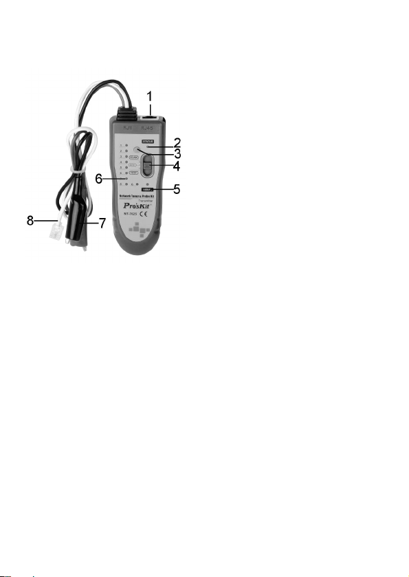
6.MT-7025 transmitter instructions
1. RJ45 Socket
Wire finding and cable status
2.
LED indicator
3. Function change button
4. Power and function switch
(SCAN/OFF/TEST)
5. Cable test verify LED
indicator
6. Cable mapping LED
indicators
7. Alligator cable
8. RJ11 cable
RJ-11 cable, for telephone line test
Alligator connector cable, red and black for telecom cable test,
Caution:
Never connect to live cable that has over AC14V or DC10V.
RJ45 socket for test STP/UTP patch cord or network.
Power and function switch
TEST: For cable mapping and open/short test.
SCAN: Transmit tone signal for cable finding.
OFF: Power off
Function change button
Power and function switch in “TEST” position:
Press function change button shortly to change scan speed
from either slow or rapid.
Press function change button and hold for 2 seconds, when
“VERIFY” LED change from flash to light up then you can
process the telecom cable open/short test.
Alligator connector clip to 2 wires terminal, it can judge the
resistance is hi or low according to brightness of the number
“1” LED, more bright means low resistance, otherwise, the
5
Page 7
resistance is high.
Power and function switch in “SCAN” position:
Press function change button shortly for frequency change
from either single or dual frequency signal for cable finding.
Press function change button and hold for 2 seconds, when
“VERIFY” LED lights up then you can take DC level polarity
test. Red Alligator connector clip positive wire and black
connect clip negative wire then “VERIFY” LED turns red, If
reversed the connection then “VERIFY” LED will turn to
green.
Cable mapping indicator
When performing cable mapping or connect to telecom
switching equipment for connection status detection,
number “1” to “8” LED will light up in order. The LED “G”
indicates the shielded conductor is connection or no
connection.
Wire finding and cable status LED indicator
For wire or cable finding and status indication
Cable test verify LED indicator
For testing result indication.
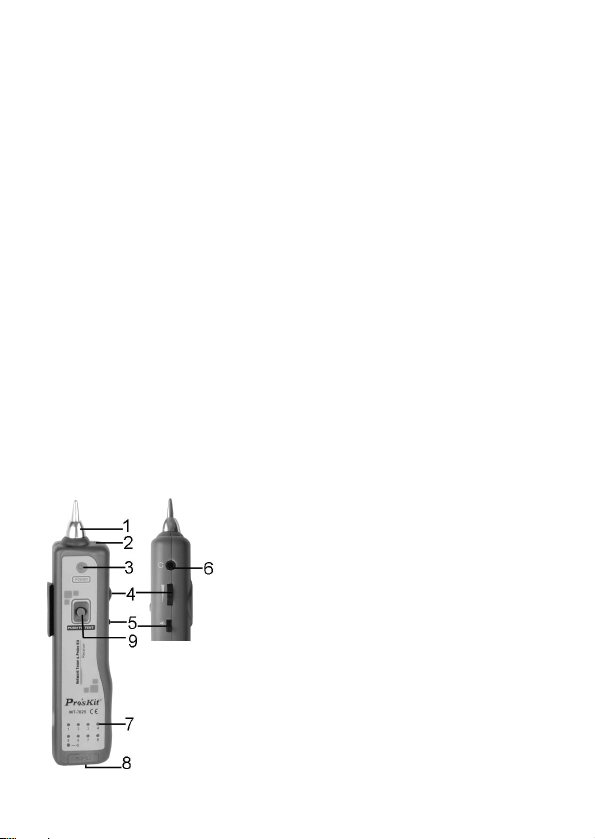
7.MT-7025 Receiver instructions
1.
Tone tested probe
2. LED illumination
3. Signal indicator
4. Volume adjustable rotary switch
5. LED illumination power switch
6. Earphone jack
7. Cable mapping LED indicators
8. RJ45 socket
9. Cable finding tested button
6
Page 8

8.How to test
*** Cable map
For testing UTP/STP/SFTP cat.5 cat.5e cat.6 cables and cat.3
telecom cables, connect both side of RJ-45 or RJ-11/12 patch
cord by plug into transmitter and receiver, slide “Power and
function switch” to “TEST” position, the “VERIFY “LED flash,
then star to process cable mapping, press “Function changed
button” to change the scan speed. Cable map and cable
status indication; please refer to below “wire map” for more
detail
Straight: 1~8/S conductors of UTP/STP patch cord are all
connected, both transmitter and receiver 1~8/G LED light up
in order at synchronous. LED “G” indicate shield connection or
no connection.
Crossover: 1~8/S conducts of UTP/STP patch cord are all
connected, both transmitter and receiver 1~8/G LED light up
in order, sequence of receiver 1~8/G indicators light up are not
follow transmitter 1~8/G indicators.
No connection: Part of 1~8/S conductor of UTP/STP patch
cord are not connected, both transmitter and receiver 1~8/G
related LED won’t light up; the other LEDs will light up in order.
Short: 1~8/S conductors of UTP/STP patch cord are all
connected, the transmitter 1~8/G LED light up in order, but
related LED of receiver 1~8/G won’t light up if it is short, the
other will light up in order.
CAT.3 telecom cable map
6P6C: LED 2~7 must light up and the other LED are off.
6P4C: LED 3~6 must light up and the other LED are off.
6P2C: LED 4~5 must light up and the other LED are off.
For CAT.3 telecom cable status indication: crossover、no
connection or short,please refer to WIRE MAP function
instruction.
7
Page 9

WIRE MAP
***Cable test with switching equipment
UTP/STP patch cord, one terminal connect to transmitter, the other
terminal connect to switching equipment, slide “Power and
function switch” to “TEST” position, transmitter 1~8 LED will light
up in order that indicate 1~8 conductors are all connected, the
related LED will off if no connection.
Note. This function just for connected testing, it can’t verify
cable crossed or short.
***Cable finding
Connect the transmitter to the tested cable, you can choose
8
Page 10

RJ-11, Alligator connector or 8P8CR J45 patch cord to
connect the tested cable according to the tested cable type.
Slide “Power and function switch” to “SCAN” position,
transmitter will transmit dual frequency tone. If you want to
change the dual frequency to single, press “Function
changed button” shortly for frequency change.
Please press and hold the “Cable finding tested button”,
put tested probe as close as possible to numerous cable or
wall that has cable inside, the speaker will sound when the
tested probe near the tested cable (Signal indicator also
lights up), if testing switching equipment, you will find
receiver sounded when close 2 or 3 wire, need to find the
clearest sounded one by receiver.
It is probable tone signal interfere by telecom switching
equipment signal when perform cable finding test that will
effect testing result, you can turn off telecom switching
equipment power if necessary.
***Telecom cable open/short testing
Slide “Power and function switch” to “TEST” position,
press test button and hold 2 seconds, the “VERIFY” LED will
change from flash to light up.
9
Page 11

Black and red Alligator connectors clip to 2 wires terminal the
RJ-11 cable plug in socket of tested wire.
The number “1” LED will light up if wires short, The number
“1” LED will off if wires open, brightness of number “1” LED
indicates the wires with hi or low resistance, LED bright
indicates low resistance, LED off indicates hi resistance.
Telephone line polarity test
Slide “Power and function switch” to “SCAN” position,
then press “TEST” button and hold 2 seconds, “STATUS”
LED will off and “VERIFY” LED lights up at the same time.
Black and red Alligator connector clip to 2 wires terminal the
RJ-11 cable plug in socket of tested wire.
Red Alligator connector clip positive wire and black connect
clip negative wire then “VERIFY” LED turns red, if reverse
the connection then “VERIFY” LED will turn to green.
***LED illumination:
If working place is dark, turns on the LED light for illumination.
***Earphone
If the working environment is noisy, wear the earphone to listen
and the sound will be more clear.
9.Battery
Low battery indicator
Slide “Power and function switch” to “SCAN” position, if
“STATUS” LED and “VERIFY” LED flash at the same time
that indicates battery voltage is lower than 6V, please
change battery.
When you perform any test, you find the LED indicator is off
or sound volume is low, please change battery.
10
Page 12

Battery replacement
1. Remove the cover of battery compartment
2. Replace new battery
3. Put the cover back
11
Page 13

10.Troubleshooting
Problem Solution
Check battery power or connection
Can’t receive the tone
signal for finding cable
Perform test with
telecom switching
equipment, can’t receive
the tone signal for
finding cable
Cable mapping LED
indication is incorrect.
The other problems.
Confirm “Power and function switch”
is on “SCAN” position
Instrument is damaged; please send it
back to us for repair.
It is probable tone signal interfere with
telecom switching equipment signal
when perform cable finding test that will
effect testing result, you can turn off
telecom switching equipment power if
necessary.
LED indicator damaged, please send it
back to us for repair.
Plug conductors are not contact to
socket, please reinsert the plug to
socket.
Instrument is damaged; please send it
back to us for repair.
12
Page 14

MT-7025 音頻/網路測試器使用說明
感謝您購買和使用 PRO’SKIT MT-7025 音頻/網路測試器,使用儀器前請仔細
閱讀說明書,閱讀後請妥善保存,以備查閱。
目錄
1. 特點概述
2. 產品特點
3. 產品規格
4. 包裝清單
5. 安全資訊
6. MT-7025 音頻發射器外觀圖
7. MT-7025 音頻接收器外觀圖
8. 使用說明
線序校對測試(Wire map)
尋線測試
電話線路短路/開路測試
電話線路正負極/DC 電壓 正負極測量
輔助照明
耳機使用
9. 電池使用
10. 簡易故障排除
1.特點概述
MT-7025 是一款集尋線、線序查對、電話線路檢測、直流電壓 正負極判斷於
一身的多功能查線器,該儀器可以在眾多線纜中快速尋找出目標線纜;可以
帶電檢測和查尋探測網路線纜,不需要拔掉網線或關閉交換機;信號傳輸距
離可達 2km 以上,可遠距離尋線作業,適用於電信網路工程施工和維護;計
算機網路工程施工和維護;以及其它導線工程施工和維護室內,室外使用。
本產品外觀小巧,攜帶方便,功能齊全,配件齊全,操作使用方便。是你得
力的檢測工具.
13
Page 15

2.產品特點
音頻發射器發射多頻脈沖信號,抗干擾能力強,信號容易被接收器探
測,信號傳輸距離可達 2km 以上,適用於電信行業遠距離尋線作業。
音頻發射器可以接入帶電乙太網路,發送音頻信號,接收器能夠探測
出信號。適用於網路布線,查線作業
音頻發射器可以接入帶電乙太網路交換機網路,在交換機開機情況下
對網線接線情況查線作業。
音頻發射器可以接入帶電電話線,發送音頻信號,接收器能夠探測出
信號。適用於電信布線,尋線作業
音頻發射器可以接入帶電電話線,查看判斷電話線路正負極。
音頻發射器可以發射單、雙音頻。
音頻發射器有 RJ45 接口,配 8P8C 跳線,自帶 RJ11 跳線,紅黑鱷魚夾
跳線,可供多種場合接入測試。
接收器有 RJ45 接口,可作 Wire map 測試遠端器,配合發射器,可檢
測網路跳線直通,短路,斷路,夾錯等跳線壓接情況,適用於檢測
UTP/STP/SFTP cat.5 cat.5e cat.6 以及 cat.3 電話線跳線。
接收器有音量大小調節電位器,可根據環境干擾信號強弱及噪音大小
調節合適音量。
接收器有耳機插座並配有耳機,可供噪音較大的環境中戴耳機尋線使
用。
接收器有一輔助照明 LED 燈,可用於光線較暗的工作場所輔助照明。
3.產品規格
發射器
頻率 1kHz
最大測試距離 2km
線序校對測試最大距離 300m
最大工作電流 ≦45mA
音頻模式 2 種音頻切換
適用連接器 RJ45(8 pin)、RJ11(6P/2C)、Alligator Clips
導通測試 有
14
Page 16

最大信號電壓 8Vp-p
功能選擇 3 種模式切換
線序指示 8 LEDs
遮蔽指示 1 LED
電話線正負極指示 有
電壓保護 AC 14V or DC 10V
低電池指示 6.0V
使用電池規格
尺寸(LxWxD) 126x49x34mm
接收器
頻率 1kHz
最大工作電流 ≦90mA
適用連接器 RJ45(8 pin)/RJ11(6 pin)
耳機插座 1
信號狀況指示 1 LED & 蜂鳴器
線序指示 8 LEDs
遮蔽指示 1 LED
LED 照明 1 LED
使用電池規格
尺寸(LxWxD) 176x42x27mm
DC 9.0V
(NEDA 1604/ 6F22 DC9V ×1pcs)
DC 9.0V
(NEDA 1604/ 6F22 DC9V ×1pcs)
15
Page 17

4.包裝明細
1. 音頻發射器 1 台
2. 音頻接收器 1 台
3. 耳 機 1附
4. 8P8C 跳線 1 條
5. 帆布 包 1 只
6. 說 明 書 1 本
7. 電 池 2顆
5.使用安全
不能在帶有強電(交流 14V, 直流 10V 以上)的線路上使用本設
備,在強電線路上使用會造成儀器損壞,並可能造成人身傷害。
在測試電話線路時,請將其它不使用的網路跳線從儀器上斷開。
非專業人員,請勿打開儀器外殼,以免造成儀器損壞。
使用結束,請將音頻發射器撥至 off 檔,以節省電源。
當電池顯示低電壓時,請及時更換電池,以保證測試結果可靠。
長時間不使用,請拿掉電池,以免造成電池漏液,造成儀器損壞。
6.MT-7025 音頻發射器外觀圖
避免將測試探頭接觸帶強電的電線裸線,以免造成儀器損壞或
人身傷害。
不要測試帶電線路超過 5 分鐘,以免造成儀器損壞。
1. RJ45
2. 尋線指示燈 STATUS
3. 功能切換按鍵
4. 功能檔位開關 SCAN/OFF/TEST
5. 測試指示燈
6. 線序指示燈
7. 鱷魚夾條線
8. RJ-11 跳線
插座
16
Page 18

RJ-11 跳線: 用於電話網路接入測試。
鱷魚夾跳線: 紅黑兩個,用於電話網路或其它線路接入測試,注意不能接入
RJ45 插座: 用於 STP/UTP 網路跳線測試或接入查線測試。
功能檔位開關
功能切換按鍵
線序指示 LED 燈: 進行線序校對或連接交換機進行通斷測試時,此 1#~8#
尋線指示燈 LED: 指示尋線狀況
測試指示燈 LED: 指示測試狀況
7.MT-7025 音頻接收器外觀圖
帶強電線路。
TEST: 網路跳線線序校對或通斷短路等測試。
SCAN: 發射音頻信號,可供音頻接收器探測接收查線。
OFF: 手動關機。
TEST 檔,短按此鍵,可進行快、慢掃描切換;長按此鍵 2 秒,VERIFY
燈由閃爍變為長亮,可進行電話線開路/短路測試,紅黑鱷魚夾分別夾
住待測線路兩端,如短路,則線路指示 LED 燈的 1#燈會長亮,反之
不亮,線路的阻抗可由燈的亮度來顯示,燈越亮,阻抗越小,越暗,
阻抗越大。
SCAN 檔,短按此鍵,發射信號單、雙音頻切換;長按此鍵 2 秒,VERIFY
燈亮,可測 TEL 線路/DC 電壓 正負極,紅、黑夾分別接正、負極時亮
紅燈,反之亮綠燈。
LED 按順序點亮,G 指示燈為線路屏蔽層連接通斷情況
1. 測試探頭
2. 輔助照
3. 信號指示 LED
4. 音量調節旋鈕
5. 輔助照明開關
6. 耳機插座
7. 線序指示 LED
8. RJ45 插座
9. 尋線測試按鍵
明 LED
17
Page 19

測試探頭: 尋線時靠近目標線,以便接收器能接收到音頻發射器發射的信號。
音量調節旋鈕 可根據需要調節接收器音量大小。
尋線測試按鍵 按壓此鍵,探頭靠近線束,可探測出音頻發射器發射的目標線。
輔助照明開關 可打開或關閉輔助照明 LED 燈
RJ45 插座 用於 STP/UTP 網路跳線測試或接入查線測試。
耳機插座 可插入耳機,方便在噪音較大的工作場尋線工作。
信號指示燈 尋線時,接收到音頻信號時,此燈點亮,信號越強,燈越亮。
線序指示 LED 進行線序校對時,此 1#~8# LED 按一定順序點亮;G 燈為線
輔助照明 LED 輔助照明使用
8.使用說明
線序校對測試(Wire map)
該功能適用於檢測 UTP/STP/SFTP cat.5 cat.5e cat.6 網路跳線及 cat.3 電話線跳
線。
將壓接好的網路跳線 RJ-45 或 RJ-11/12 水晶頭插入音頻發射器和接收器 RJ-45
測試插座,發射器功能切換開關拔至 TEST 檔位,VERIFY 燈閃爍,儀器開始
對跳線排列線序掃描,按發射器功能切換按鍵,可以切換快慢掃描方式。
掃描線序排列顯示如下(詳細請參考 WIRE MAP 圖)
直通 UTP/STP 網路跳線 1~8/S PIN 全部連接,音頻發射器和接收器 1~8/G
指示燈按先後順序依次同步點亮,G 指示燈為線路屏蔽層連接通斷。
交叉 UTP/STP 網路跳線 1~8/S PIN 全部連接,音頻發射器 1~8/G 指示燈按
先後順序依次點亮,接收器 1~8/G 指示燈按實際壓接錯位順序依次點亮。
斷路 UTP/STP 網路跳線 1~8/S PIN 連接有斷路,音頻發射器和接收器
1~8/G 指示燈對應斷路位置 LED 燈不亮,其它燈按先後順序依次同步點亮。
短路 UTP/STP 網路跳線 1~8/S PIN 全部連接,音頻發射器 1~8/G 指示燈按
先後順序依次點亮,接收器 1~8/G 指示燈對應短路位置燈不亮,其它燈按
先後順序依次點亮。
CAT.3 電話線跳線---直通測試
6P6C 跳線---音頻發射器和接收器 2~7 指示燈按先後順序同步點亮,其它燈
不亮。
6P4C 跳線---音頻發射器和接收器 3~6 指示燈按先後順序同步點亮,其它燈
不亮。
6P2C 跳線---音頻發射器和接收器 4~5 指示燈按先後順序同步點亮,其它燈
不亮。
CAT.3 電話線跳線---交叉、斷路、短路等,同網路跳線測試類同,具體請
參考 WIRE MAP.
路屏蔽層連接通斷
18
Page 20

WIRE MAP
---帶交換機網路測試
對於 UTP/STP 網路跳線,可以用一端連接音頻發射器,另一端連接在網路交
換機上,檔位開關拔至 TEST 檔位,音頻發射器 1~8指示燈按先後順序點亮,
表示網路跳線 1~8 PIN 全部連通,否則,對應斷路位置不亮;
注 此測試方法只能測試網線路通斷,不能檢測交叉或短路。
尋線測試
音頻發射器接入待測目標線路,接入方式根據實際情況,可選擇用
RJ-11 跳線或紅黑鱷魚夾跳線或 8P8C 網路跳線接入;
接好跳線後,音頻發射器檔位開關拔到 SCAN 檔位,此時音頻發射器
19
Page 21

發射雙音頻信號,如需要選擇單音頻信號,可按功能切換按鍵,切換
單、雙音頻;
音頻接收器,按住尋線測試按鍵,測試探頭靠近線束中的每根網線或
埋線牆壁,當接收器喇叭響起(信號指示燈同時點亮),探頭靠近的線
就是所要查找的目標線。如網路交換機工作中,尋找的線束中會有 2~3
根線都響,聲音最清晰的那根線是目標線。
注意 帶電查尋電話局域網線路時,因不同電話交換機信號頻率不
同,可能會有與本音頻發射器發射信號衝突,造成無法探測出信號情
況,如有必要,可以關閉電話交換機進行查尋線工作
查尋示意圖
電話線路短路/開路測試
音頻發射器檔位開關撥至 TEST 檔,長按此鍵 2 秒,VERIFY 燈由閃爍變為
長亮;
紅黑鱷魚夾分別夾住待測線路兩端,或用儀器自帶 RJ-11 跳線插入待測
RJ-11 插座;
如短路,則線路指示 LED 燈 1#長亮,開路則不亮。線路的阻抗可由燈的
亮度來顯示,燈越亮,阻抗越小,越暗,阻抗越大;
電話線路正負極/DC 電壓 正負極測量
音頻發射器檔位開關撥至 SCAN 檔,長按此鍵 2 秒,STATUS 燈熄滅同時
VERIFY 燈亮;
紅黑鱷魚夾分別夾住待測線路兩端,或用儀器自帶 RJ-11 跳線插入待測
RJ-11 插座;如紅、黑夾分別接正、負極時亮紅燈,反之亮綠燈。
20
Page 22

輔助照明
如工作環境光線不足,可開啟輔助照明 LED。
耳機使用
如工作環境噪音太大,可使用耳機,方便尋線測試。
9.電池使用
電池低電壓顯示
音頻發射器功能檔位開關撥至 SCAN 檔,如 STATUS 燈和 VERIFY 燈同時
閃爍時,電池電壓低於 6V,需要更換電池。
音頻接收器探測發射信號中的音頻發射器跳線時,聲音小,信號指示燈不
亮時,表示電池供電不足,需更換電池。
電池裝卸
21
Page 23

10.簡易故障排除
故障 排除
檢查電池,如電壓低,更換電池
無法探測音頻發射器信號
帶電測試電話局域網路,無
法探測音頻發射信號
線序校對顯示不正確
其它功能異常 儀器故障,返回經銷商維修
發射器檔位不正確,撥至 SCAN 檔
儀器故障,返回經銷商維修
可能電話網路信號頻率與本音頻發
射信號衝突,可關閉電話交換機
LED 指示燈壞,返回經銷商維修
網線沒插好,重新插入 RJ-45 插座
22
Page 24

©2013 Prokit’s Industries Co., LTD. All rights reserved 2013001(C)
23
 Loading...