

Page 1
MT-5210 3 1/2 LCR Meter
User’s Manual
1st Edition, 2011
©2011 Copy Right by Prokit’s Industries Co., Ltd.
1
Page 2
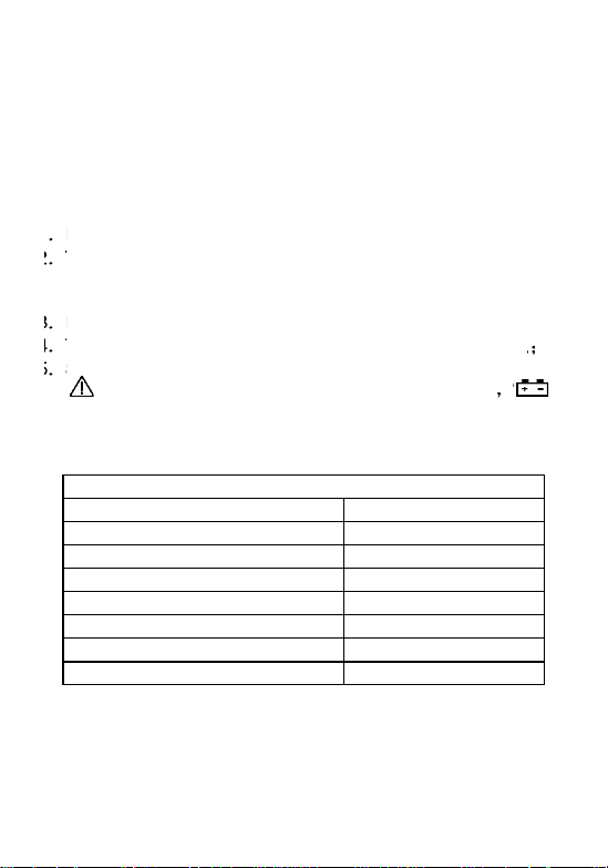
1. SUMMARIZE
Function Model
Inductance
2mH-20H
Capacitance
2nF-1000uF
Resistance
200Ω-20MΩ
Diode test
√
Transistor Test
√
Continuity buzzer
√
Data Hold
√
Alarm
√
The meter is a stable multimeter with 3 2/1 LCD displays , 9V drive by
battery. It's widely used on measuring Inductance, resistance,
capacitance, diode, transistor rest and continuity buzzer. It’s an ideal
tool for lab, factory and family.
2. SAFETY NOTE
The meter meets the standards of IEC1010. Read the operation
manual carefully before operation.
1 Do not input DC Voltage or AC Voltage.
2 The voltage below 36V is safety. To avoid electric shock, check
whether the test leads are connected correctly, whether the
insulation is good when measuring over 36DCV or 25ACV , .
3 Remove the test leads when changing function and range.
4 To select correct function and range, beware of error operation.
5 SAFETY SYMBOLS
“ ”THE OPERATOR MUST REFER TO THE MANUAL “ ” LOW
BATTERY
3. Technical data
2
Page 3
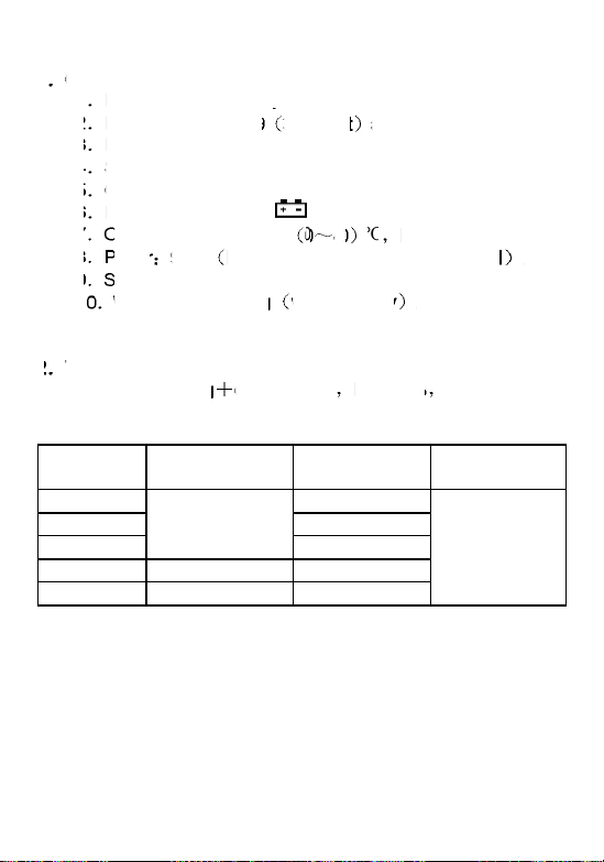
4. CHARACTERISTIC
RANGE
ACCURACY
RESOLUTION
MEASURE
FREQUENCY
2mH
1uH
20mH
10 uH
200mH
±(2.0%+5d)
100uH
2H
±(5.0%+5d)
1mH
20H
±(5.0%+15d)
10mH
About 200Hz
1 GENERAL
1-1 Displaying: LCD displaying.
1-2 Max. displaying: 1999 3 1/2 digit auto polarity indication.
1-3 Measuring method: dual slope A/D conversion.
1-4 Sampling rate: approx. 3 times/second.
1-5 Over range indication: the MSD displays“1”.
1-6 Low battery indication:“ ” appears.
1-7 Operation environment: 0 40 ℃ R.H.<80% .
1-8 Power 9V×1 NEDA1604/6F22 or equivalent model .
1-9 Size:189×97×35mm
1-10 Weight: approx. 362g without battery .
1-11. Accessory: operation manual, gift box, test leads
2 TECHNICAL CHARACTERISTIC
Accuracy:±(a%× rdg d) at (23±5)℃ R.H.<75%
2-1.Inductance (L)
1H=10³mH=106uH
3
Page 4
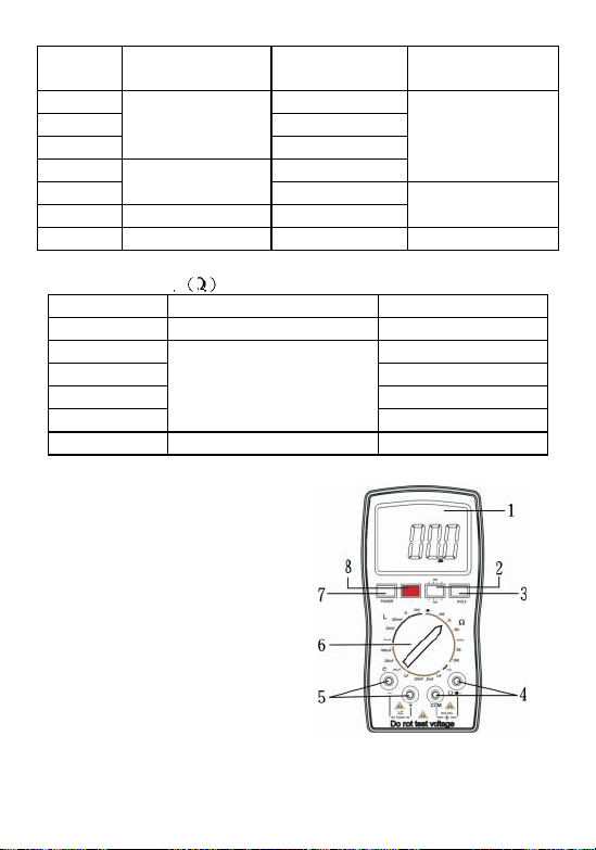
2-2.CAPACITANCE(C)
RANGE
ACCURACY
RESOLUTION
MEASURE
FREQUENCY
2nF
1pF
20nF
10pF
200nF
±(1.0%+5d)
100pF
2uF
1nF
About 200Hz
20uF
±(2.0%+5d)
10nF
200uF
±(5.0%+5d)
100nf
About 16Hz
1000uF
±(5.0%+25d)
1uF
About 8Hz
RANGE
ACCURACY
RESOLUTION
200Ω
±(0.8%+5d)
0.1Ω
2kΩ
1Ω
20kΩ
10Ω
200kΩ
100Ω
2MΩ
±(0.8%+3d)
1kΩ
20 MΩ
±(1.0%+15d)
10 kΩ
2-3.RESISTANCE Ω
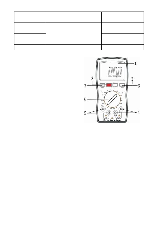
5. OPERATION
5.1 Front panel description
1. LCD display
2. Transistor test jack.
3. Hold switch: use hold the
measuring data.
4. Input port: the input port of
resistance and diode test.
5. Input port: the input port of
inductance and capacitance
measuring..
6. Range selector
7. Power switch.
8. Light diode: using in the Continuity buzzer
4
Page 5

5.2 CONSIDERATION OF MEASUREMENT
(1) This LC METER is intended for measuring the capacitance value
of a capacitor, the inductance value of an inductor. It is not
intended for determining the “Q” factor for above reactive
components. Misleading readings may be obtained if the
measurement of the inductance or cap acitance of a resistor is
attempted.
(2) When measuring components in circuit, the circuit must be
switched off and de-energized before connecting the test leads.
(3) For all measurements, should connect BLACK test lead to “ -”
terminal and RED test lead to “+” ter minal.
5.3 INDUCTANCE (L) MEASUREMENT PROCEDURE
(1) Press the POWER button to turn the power on
(2) Select the range switch for the maximum expected inductance.
(3) Connect the alligator clips to the inductor leads.
(4) Read the display. The value is direct reading in th e electrical units
(uH, H) indicated at the selected switch. If DISPLAY show “1”. It
indicates on Out-of-Range measurement. If the display indicates
one of more reading zeros, shift to the next lower range scale to
improve the resolution of the measurement .
NOTE:
(a) If the inductance value is unmarked, start from the 2mH range and
keep increasing until the over range indication goes off and a
reading is obtained.
(b) Very low inductance measurement should be performed by using
extremely short leads in order to av oid introducing any stray
inductance.
(c)This instrument is not intended for determining the “Q” factor for the
inductor. Misleading readings may be obtained if the measurement
of the inductance of a resistor is attempted.
5
Page 6

5.4 CAPACITANCE(C) MEASURING PROCE DURE
(1) Press the POWER button to turn the power on
(2) Select the range switch for the maximum expected capacitance.
(3) Fully discharge any capacitors.
(4) Connect the alligator clips to the capacitor leads.
(5) Read the display. The value is direct reading in the electric al unit
(nF, uF) indicated at the selected range switch. If DISPLAY show
“1”, It indicate on Out-of-Range measurement. If the display
indicates one or more leading zeros, shift to the next lower range
scale to improve the resolution of the measurement.
NOTE:
(a) If the capacitance value is unmarked, start from the 2nF range
and keep increasing until the over -range indication goes off and a
reading is obtained.
(b) A shorted capacitor will read over-range on all ranges. A
capacitance with low voltage leakage will r ead over range, or a
much higher value than normal.
An open capacitor will read zero on all ranges (possible a few pF
on 2nF range, due to stray capacitance of the instrument).
(c) Very low capacitance measurement should be performed by using
extremely short leads in order to avoid introducing any stray
inductance
(d) When using the optioned test leads, remember that the leads
introduce a measurable capacitance to the measurement. As a
first approximation, the test capacitance did measured by opening
the leads at the trips, recording the open circuit value and
subtracting the value.
(e) Capacitors, especially electrolytic, often have notoriously wide
tolerances. Do not be surprised if the measured value is greater
than the value marked on the capacitor, unless it is a close
tolerance type. However, value is seldom drastically below the
rated value.
6
Page 7

5.5 RESISTANCE (Ω) MEASURING PROCEDURE
(1) Press the POWER button to turn the power on
(2) Select the range switch for the maximum expected resistance.
(3) Insert the black test leads into the “COM” jack, and the red one
into the “V/Ω/Hz” jack;
(4) Turn the range switch to resistance po sition, and then connect the
test leads at the two ends of the resistor.
(5) If DISPLAY show “1”, It indicate on Out -of-Range measurement. If
the display indicates one or more leading zeros, shift to the next
lower range scale to improve the resolution of the measurement.
Note:
(a) When input is open circuit, it will display status 1;
(b) When measuring resistance on line, ensure that all power of
circuit tested are turn down and all capacitor are discharged
completely;
(c) Never input voltage if in resistance measurement mode!
(d) It normal for resistance higher than 1MΩ that the reading data is
not stable for the first several seconds;
5.6 Transistor hFE
1. Press the POWER button to turn the power on
2. Turn the range switch to “hFE” position;
3. To determine the transistor ’s type, NPN or PNP, insert the emitting,
base and collector electrode into the corresponding jacks in testing
accessory.
5.7 DIODE AND CONTINUITY TEST
1. Press the POWER button to turn the power on
2. Insert the black test leads into “COM “jack, and the red one into the
“Ω ” jack;
3. connect test leads in parallel to the diode tested, with the red test
leads to the anode and the black to cathode, then the reading value
will be approximate forward voltage drop of the diode;
4. Connect pencils to two points of the circuit to be tested, if buzzer
sounds, then the resistance between the two points is lower than
7
Page 8

(60±20) Ω.
5.8 DATA HOLD
Press HOLD, the peak value of current data will be keep displaying on
LCD; press it again to cancel this functio n.
6. MAINTENANCE
DO NOT try to verify the circuit for it’s a precision meter.
1. Beware of waterproof, dustproof and shockproof.
2. Do not operate and store the meter in the circumstance of high
temperature, high humidity, and flammability, explosive an d strong
magnetic field.
3. Use the damp cloth and soft solvent to clean the meter, do not use
abrasive and alcohol.
4. If do not operate it for a long time, should take out the battery.
5. When LCD displays “ ” symbol, should replace the battery as
below:
●The specifications are subject to change without notice.
●The content of this manual is regarded as correct, error or omits
Pls. contact with factory.
●We hereby will not be responsible for the accident and damage
caused by improper operation.
●The function stated for this User Manual cannot be the reason of
special usage.
8
Page 9

MT-5210 3 1/2 電感.電容.電阻表 LCR 電錶
功能類型
電感值
2 mH-20H
電容值
2nF-1000uF
電阻值
200O-20MO
二極體測試
v
電晶體測試
v
連續性蜂鳴器
v
數據保持
v
警示
v
操作手冊
1. 概述
本儀表是一台有 3 1/2 LCD 液晶顯示,使用 9 伏特電池的穩定電錶。廣
泛地運用在測量電感,電阻,電容,二極體電晶體和連續性蜂鳴器。適用
於實驗室,工廠和一般家庭使用
2. 安全注意事項
儀表符合IEC1010 的標準,操作之前請仔細閱讀操作手冊。
1. 不要輸入直流電壓或者交流電壓。
2. 電壓低於 36V 是安全的。為避免觸電,測量超過 36DCV 或 25ACV
前檢查測試導線是否連接正確 ,是否絕緣良好
3. 當改變功能和範圍時,除去測試線。
4. 要選擇正確的功能和範圍,謹防錯誤操作。 ;
5. 安全符號
“ ” 操作者必須參見手冊,“ ” 低電壓指示
3. 技術數據
9
Page 10

4. 特性
範圍
準確度
分辨率
測量頻率
2mH
1uH
20mH
10 uH
200mH
±(2.0%+5d)
100uH
2H
±(5.0%+5d)
1mH
20H
±(5.0%+15d)
10mH
About
200Hz
範圍
準確度
分 辨
率
測量頻率
2nF
1pF
20nF
10pF
200nF
±(1.0%+5d)
100pF
2uF
1nF
About
200Hz
20uF
±(2.0%+5d)
10nF
200uF
±(5.0%+5d)
100nf
About
16Hz
1000uF
±(5.0%+25d)
1uF
About
8Hz
1.一般
1-1. 螢幕︰ LCD 液晶螢幕。
1-2. 最大顯示︰ 1999 (3 1/2 digit) 自動極性指示。
1-3. 測量方法:雙斜率 A / D 轉換。
1-4. 採樣率︰約3 次/秒。
1-5. 超過測試範圍顯示︰ MSD 顯示 “1”
1-6 低電壓顯示: 出現 “ ”
1-7. 操作環境︰ (0 ~40 )℃,R.H.<80%
1-8. 電源︰9V (NEDA1604/6F22 或同等類型) .
1-9. 尺寸︰189×97×35mm
1-10.重量︰ 約 362 克(不包括電池) .
1-11. 配件︰ 操作手冊,禮品盒,測試線
2.技術特性
精度:±(a%×讀數值+ d)在溫度(23 ± 5)℃,相對濕度 <75% (產品
生產後 1 年保證期)
2-1. 電感(L)
1H=10³mH=106uH
2-2.電容(C)
10
Page 11
2-3.電阻(Ω)
範圍
準確度
分辨率
200Ω
±(0.8%+5d)
0.1Ω
2kΩ
1Ω
20kΩ
10Ω
200kΩ
100Ω
2MΩ
±(0.8%+3d)
1kΩ
20 MΩ
±(1.0%+15d)
10 kΩ
5. 操作
5.1 面板說明
1. LCD 螢幕
2. 電晶體測試孔。
3. 保持按鍵︰利用保存測量數據。
4. 探測棒(測試線)插入孔︰ 電阻
和二極體的測試。
5. 探測棒(測試線)插入孔︰ 電感
和電容的測試。
6. 範圍旋鈕
7. 電源開關。
8. 發光二極體:在連續性蜂鳴器方
面使用
5.2 測量注意事項
(1) 這台 L.C 測試器用於測量一個電容器的電容值、電感的電感值,其目
的不是確定的“Q”因素對上述的反應。
(2) 當測量零件內部迴路時,這個迴路必須在沒有通電的狀態下線之前 ,
電路必須被關掉並且切斷。
(3) 所有的測量應連接測試線黑“ - ” 紅色測試線“+”
5.3 電感(L) 測量步驟
(1) 打開電源。
(2) 轉動選擇開關到電感預期的最大值 。
(3) 把鱷魚夾子和待測電感連結起來 。
(4)讀取螢幕顯示數值,電感值單位(uH,H)裡的直接讀取 如果螢幕顯示
“1”表示測量結果超過選定測量範圍。如果螢幕顯示一個或多個零在數
字前面,切換到下一個較低的範圍檔位提高分辨率 。
11
Page 12

注意︰
(a) 如果不知道待測物品電感值 ,從 2mH 範圍開始並且持續增加,直到
超量指示熄滅及讀取到讀值 。
(b) 為了避免雜訊,測量非常低的電感值應該使用極其短的測試線執行
(c) 此儀錶不能用以測量電感的品質好壞 , 同一電感量存
在不同阻抗時測得的電感值不同 .
5.4 電容量(C) 測量步驟
(1) 打開電源。
(2) 轉動選擇開關到電容預期的最大值 。
(3) 充分的執行任何電容器放電 。
(4) 把鱷魚夾子和電容器導線連結起來 。
(5) 讀取螢幕顯示的數值,電容值單(nF, uF)裡的直接讀取,如果螢幕顯
示“1”表示測量結果超過選定測量範圍 。如果螢幕顯示一個或多個零
在數字前面,切換到下一個較低的範圍檔位提高分辨率 。
注意︰
(a) 如果不知道待測物品電容量值 ,從 200pF範圍開始並且持續增加,
直到超量指示熄滅及讀取到讀值 。
(b) 一個短路的電容測量時會顯示超過量測範圍的讀值 。與正常的電容
相比較,有低電壓漏電的電容量讀值將會較高或超過範圍 。
一個開放閱讀零電容將在所有範圍 (可能是幾 pF的範圍上 200pF,
由於雜散電容的儀器) .
(c) 為了避免雜訊,測量非常低的電容量應該使用極其短的測試線執行。
(d) 當使用任選的測試表筆時,記住表筆可能引入一個電容.首先,測試
表筆應在打開筆尖的情況下 ,測出改表筆的電容,記錄其開路值並
從測試結果中減去此值
(e) 電容器,特別是電解電容,往往有廣泛的公差。不要感到驚訝,如
果測量值大於標在電容器上的值 ,除非它是一個緊公差,不管如何
測量值很少大幅低於額定值
5.5電阻(Ω) 測量步驟
(1)打開電源。
(2) 轉動選擇開關到電阻預期的最大值 。
(3) 黑色測試線插入到的“COM”插孔,紅色測試線插入“V /Ω/赫茲”插孔;
(4) 旋轉開關將檔未轉到要測量的範圍 ,然後把測試線接觸電阻器的兩
端。
(5) 如果螢幕顯示“1”表示測量結果超過選定測量範圍 。如果螢幕顯示一
個或多個零在數字前面,切換到下一個較低的範圍檔位提高分辨率 。
12
Page 13

注意︰
(a) 當輸入是開路時,它將顯示 ”1”
(b) 測量線上電阻時, 要確認被測電路所有電源已關斷而所有電容都已
完全放電
(c) 如果在電阻測量模式決不輸入電壓
(d) 高於 1MΩ 的阻抗前幾秒的讀值不穩定是正常的
5.6 電晶體 hFE
1. 打開電源
2. 旋轉範圍切換到“hFE”位置;;
3. 要確定電晶體的類型,NPN 或 PNP,插入對應的插孔測試。
5.7 二極體和連續性測試
1. 打開電源。
2. 黑色測試線插入到的“COM”插孔,紅色線插到“Ω”插孔;
3. 測試導線連接在平行的二極體測試 ,測試導線紅色的陽極和陰極的黑
色,然後閱讀值將接近正向壓降的二極體 ;;
4. 連接兩點的電路進行測試 ,如果蜂鳴器發出聲音,則在兩點之間的電
阻小於(60 ± 20)Ω。
5.8 數據處理
按 HOLD 鍵,峰值電流的數據將繼續顯示在液晶顯示器 , 再按一次取消
了這個功能。
6.
不要試圖驗證這是一個精密儀表 。
1.注意要防水,防塵和防震。
2.不要在高溫,高濕度,易燃,易爆和高磁場的環境下操作及存放。
3.使用濕布和軟性溶劑來清潔設備 ,不使用磨料和酒精。
4.如果很久不使用,請取出電池。
5.當液晶顯示“ ”符號,應更換電池
本說明書如有改變,恕不另行通知
本說明書的內容被認為是正確的 ,若用戶發現有錯誤、遺漏
等,請與生產廠家聯繫。
本公司不承擔由於用戶錯誤操作所引起的事故和危害 。
本說明書所講述的功能,不作為將產品用做特殊用途的理
由。
13
Page 14

©2011 Prokit’s Industries Co., LTD. All rights reserved 2011001(T)
14
 Loading...