

Page 1
3 1/2 HAND HELD
DIGITAL CLAMP METER
D
L
O
H
L
A
T
I
E
H
L
G
D
N
A
H
I
D
D
2
/
1
3
6
6
2
3
T
-
M
M
E
T
E
R
P
L
C
M
A
T
N
T
E
O
S
I
T
E
R
S
N
L
U
I
A
V
)
0
0
5
(
P
N
T
O
O
I
1
6
T
2
I
W
H
T
I
N
U
E
X
T
E
L
A
N
R
A
C
A
O
F
F
0
0
0
1
Ω
M
0
0
0
2
Ω
M
0
2
0
0
2
K
0
2
V
C
A
0
5
7
0
0
0
1
V
C
D
0
0
2
Ω
K
0
2
2
E
X
T
E
Ω
M
0
Ω
M
0
0
0
2
O
F
F
T
I
N
U
L
A
N
R
M
O
C
VΩ E
V
0
0
0
1
V
~
0
5
7
M
A
X
Ω
0
0
2
0
0
0
1
V
C
D
V
C
A
0
5
7
0
0
2
0
0
0
1
A
C
A
X
T
MT-3266
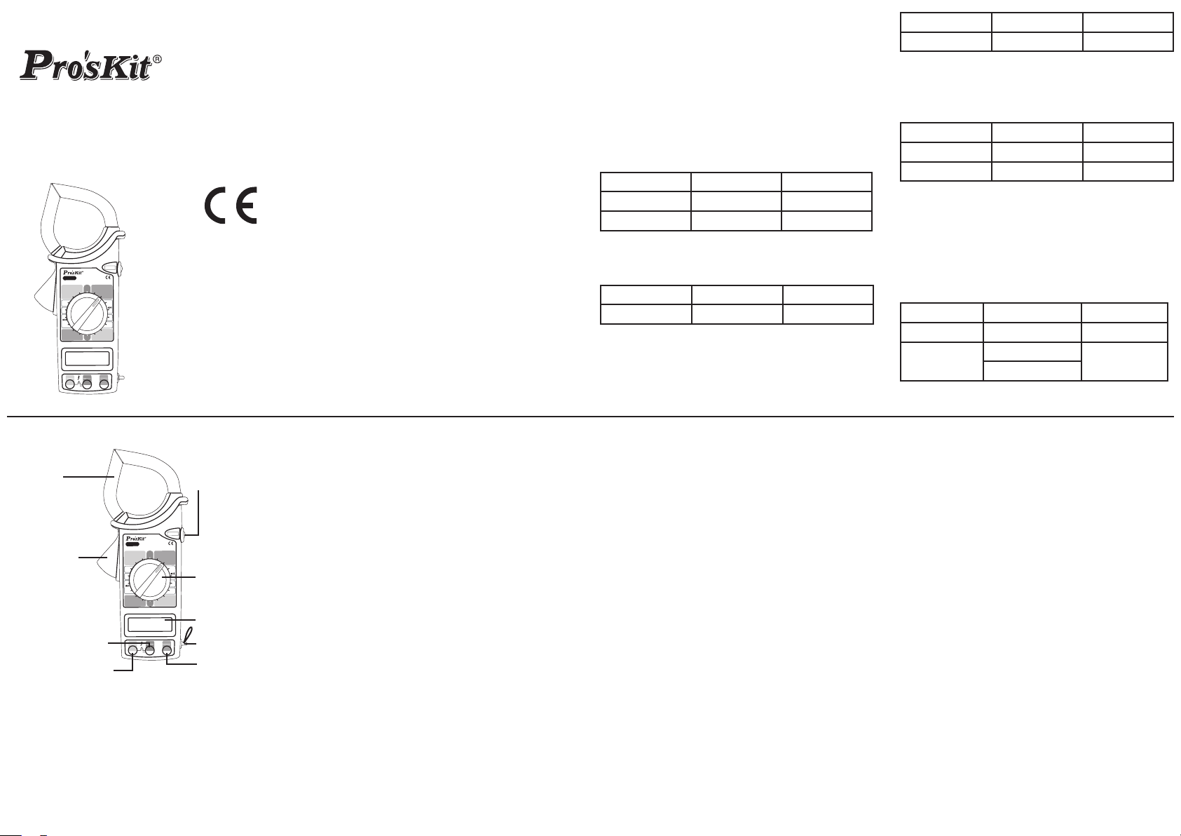
DIGITAL CLAMP METER
OPERATION MANUAL
• INTRODUCTION
Clamp meter is 3 1/2 digit LCD and standard 9V battery
operation for measuring DC voltage, AC and DC current,
resistance and continuity test. All overload protection is
provided. It is matching with 500V insulation test attach-
ment for insulation test function. The knob switch design
makes manual operation workable & function selector,
range selector and power switch are all on one knob. It is
a good tool for electric measurement.
• GENERAL SPECIFICATION
1. Display: 3 1/2 digit LCD and max. 1999 counts.
2. Polarity : Auto
3. Over range indication: Only the MSD “1” display.
4. Sampling rate: 3 times per second.
5. Low voltage indication: “LOBAT” sign
6. Hold: Data hold
7. Power: 9V carbon-zinc battery or alkaline battery
8. Battery life: approx. 200 hours (alkaline battery)
Approx. 150 hours (carbon-zinc battery)
1 2 3
9. Working environment: 0˚C~50˚C,< 80% RH.
10. Storage environment: -20˚C~60˚C, < 80% RH.
11. Dimension: 230(L)mm x 70(W) mm x 37(D)mm.
12. Weight: approx. 310g (including battery).
13. Max. jaw opening: 50mm
• ELECTRICAL SPECIFICATION:
Accuracy is ± (percentage of reading + number of digit)
at 23±5˚C, <80%RH.
1.AC current
Range Accuracy Resolution
200A
1000A
±(3%+5d)
±(3%+5d)
Frequency response: 50~60Hz
Indication: Average (rms of sine wave)
2. DC voltage
Range Accuracy Resolution
1000V
±(0.8%+2d)
Input impedance: 9MΩ
Max. overload protection: 1000 V DC
3. AC voltage
100mA
1A
1V
Range Accuracy Resolution
750V ±(1.2%+4d) 1V
Frequency response: 50~400Hz
Input impedance: 9MΩ
Max. overload protection: 750 V AC rms
4. Resistance
Range Accuracy Resolution
200Ω ±(1%+3d) 0.1Ω
20kΩ ±(1%+1d) 10Ω
Max. overload protection: 250 V DC / AC rms
5. Continuity test
Range: 200Ω
When resistance less than 75Ω build-in buzzersounds.
Max. overload protection: 250VDC/AC RMS
6. High resistance(with 500V Insulation attach-
ment)
Range Accuracy Resolution
20MΩ
2000MΩ
±(2%+2d)
≤500MΩ
>500MΩ
±(4%+2d)
±(5%+2d)
10KΩ
1MΩ
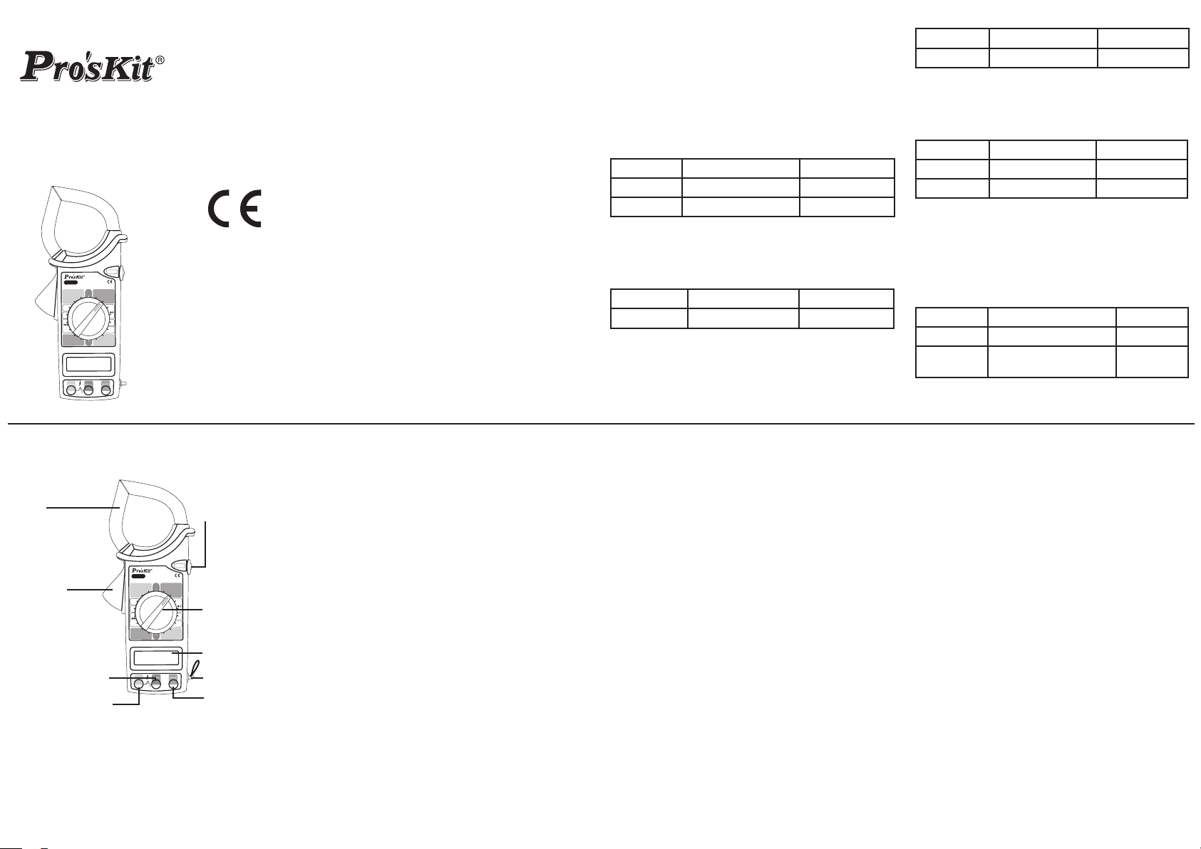
• FRONT PANEL DESCRIPTION:
E
L
D
D
R
S
N
U
I
E
X
2
1
L
A
T
I
G
I
T
N
T
E
O
I
L
A
N
U
T
E
L
A
N
R
Ω
M
0
0
0
M
0
2
0
0
2
0
0
0
A
X
T
D
L
O
H
S
T
E
R
T
I
Ω
K
0
2
Ω
0
0
2
0
0
0
1
V
C
D
V
C
A
0
5
7
A
C
Hold switch
Knob switch
LCD
Hand bell
Insulation
attachment
terminal
Clamp
Pressure
COM terminal
V/Ω INPUT terminal
2
/
1
3
6
6
2
3
T
-
M
L
C
A
P
N
T
O
O
I
1
6
T
2
I
W
H
A
C
A
0
0
0
1
0
0
2
V
C
A
0
5
7
0
0
0
1
V
C
D
0
0
2
Ω
K
0
2
Ω
M
0
2
Ω
M
0
0
0
2
T
I
N
U
E
X
T
E
L
A
N
R
VΩ E
V
0
0
0
1
V
~
0
5
7
A
X
M
H
D
N
A
H
E
T
M
E
P
M
V
)
0
0
5
(
O
F
F
O
F
F
M
O
C
• OPERATION:
1. AC current measurement:
a. Set the knob switch to ACA 1000A position.
b. Set the hold switch is loosing state.
c. Press the “PRESSURE” down and clamp a wire. If
clamp two or over wire, measure is useless.
d. If the reading less than 200A, change the range to
“200A” position in order to improve the Resolution.
e. If in dark, press hold switch, and read the data in
light place.
2. AC and DC voltage measurement:
a. Set the knob switch to DCV1000V or ACV750V po-
sition.
b. Set the hold switch is loosing state.
c. Connect the red lead to “V/Ω” jack and the black
lead to “COM” jack.
d. Connect the probes across circuit to be tested.
3. Resistance measurement:
a. Set the knob to proper resistance position.
b. Set the hold switch is loosing state.
c. Connect the red test lead to “V/Ω” jack and the test
black lead to “COM” jack.
d. Connect the probes across resistance to be tested.
e. When checking in-circuit resistance, be sure the cir-
cuit under test has all power removed and that all
capacitor are fully discharged.
4. Continuity test:
a. Set the knob switch to 200Ωposition.
b. Connect the test lead to “V/Ω” jack and the test black
lead to “COM” jack.
c. If resistance value less than 75Ωbetween two test
leads, buzzer sounds.
5. High resistance measurement:
a. Set the knob switch to “EXTERNAL UNIT” 20MΩ or
2000MΩ position, reading is unstable.
b. Connect three plugs of test attachment to corre-
spond jacks on front panel.
c. Set the knob switch and attachment switch to
2000MΩ position separately.
d. Connect resistance to input terminal of attachment.
e. Set power switch of attachment to “ON” position,
press “PUSH” button, indication lamp is light and
reading. If reading less than 19MΩ, separately
change meter and attachment range switch to
20MΩ in order to resolution.
Note:
1. 500V insulation attachment is optional accessories.
2. If 500V insulation attachment low voltage indication
lamp is light, should replacement battery.
5 6 74
• MAINTENANCE:
1.Your Digital Multi-meter is a preci-
sion electronic device. To avoid dam-
age, do not tamper with the circuitry.
Note:
a. Don’t input over 1000VDC or 750Vrms.
b. Don’t input voltage signal on resistance range.
c. Before replacement battery, must remove leads
from circuit and be turn off power.
2. Replacement battery:
If appears “LOBAT” on LCD, user should immediately
replace battery.
PROKIT’S INDUSTRIES CO., LTD.
http://www.prokits.com.tw
E-mail : pk@mail.prokits.com.tw
©2012 Prokit’s Industries Co., LTD. All rights reserved. 2012001(C)
Page 2
3 1/2 數位鉤錶
D
L
O
H
L
A
T
I
E
H
L
G
D
N
A
H
I
D
D
2
/
1
3
6
6
2
3
T
-
M
M
E
T
E
R
P
L
C
M
A
T
N
T
E
O
S
I
T
E
R
S
N
L
U
I
A
V
)
0
0
5
(
P
N
T
O
O
I
1
6
T
2
I
W
H
T
I
N
U
E
X
T
E
L
A
N
R
A
C
A
O
F
F
0
0
0
1
Ω
M
0
0
0
2
Ω
M
0
2
0
0
2
K
0
2
V
C
A
0
5
7
0
0
0
1
V
C
D
0
0
2
Ω
K
0
2
2
E
X
T
E
Ω
M
0
Ω
M
0
0
0
2
O
F
F
T
I
N
U
L
A
N
R
M
O
C
VΩ E
V
0
0
0
1
V
~
0
5
7
M
A
X
Ω
0
0
2
0
0
0
1
V
C
D
V
C
A
0
5
7
0
0
2
0
0
0
1
A
C
A
X
T
MT-3266
3 1/2 數位鉤錶 使用說明書
一、概述
3 1/2 數位鉤錶是 一種由標準 9V電池驅 動, LCD顯示的
3 1/2位數字萬用錶。採用全 功能 過載 保護電路,可測量
交、直流電壓、交流電流、電阻及通斷測試。可配500V
絕緣測 試附件,具有絕緣測試功能。儀表結構設計合理,
採用旋轉式開關,集功能選擇、量程選擇、電源開關于一
體挾帶方便,是電器測量的理想工具。
二、一般特性
1. 顯示 : 3 1/2位LCD,最大顯示1999
2. 極性顯示 : 自動極性顯示
3. 超量程顯示 : 最高位顯“ 1 ”
4. 採樣速率 : 3次/秒
5. 低電壓顯示 :“ LOBAT ”提示符號
6. 數據保持 : 各功能和量程有此特點
7. 電池 : 9V鹼性電池或碳鋅電池
8. 電池壽命 : 鹼性電池約200小時
碳鋅電池約150小時
9. 工作環境 : 溫度0˚C~50˚C
相對濕度小于80%
10.儲存環境 : 溫度-20˚C~60˚C
1 2 3
相對濕度小于80%
11. 外形尺寸 : 230mm(長)×70mm(寬)×37mm(厚)
12. 重量 : 310g(含電池)
13. 鉗頭最大張口: 50mm
三、技術特性
溫度23±5˚C相對濕度小于80%。
準確度為±(a%讀數+字數)。
1.交流電流
量程 準確度 分辨率
200A
1000A
±(3%讀數+5字)
±(3%讀數+5字)
頻率響應: 50~60Hz。
顯示: 正弦波有效值, 平均值響應。
2.直流電壓
量程 準確度 分辨率
1000V
輸入阻抗: 9MΩ。
最大過載保護: 1000V直流。
±(0.8%讀數+2字)
100mA
1A
1V
3.交流電壓
量程 準確度 分辨率
750V
±(1.2%讀數+4字)
1V
頻率響應: 50~400Hz。
輸入阻抗: 9MΩ。
最大過載保護: 750V交流有效值。
4.電阻
量程 準確度 分辨率
200Ω
20KΩ
±(1.0%讀數+3字)
±(1.0%讀數+1字)
0.1Ω
10Ω
最大過載保護︰250V 直流或交流有效值。
5.通斷測試
量程: 200Ω。
當測試回路阻值低于75Ω時, 內置蜂鳴器發聲。
最大過載保護: 250V直流或交流有效值。
6.高阻測試(配500V絕緣測試附件)
量程 準確度 分辨率
20MΩ
2000MΩ
±(2%讀數+2字)
≦500MΩ±(4%讀數+2字)
>500MΩ(5%讀數+2字)
10KΩ
1MΩ
四、外觀說明
鉗頭
鉗頭開關
“COM”公共地端
VΩ電壓電阻輸入端
3
6
6
2
3
T
-
M
C
P
T
O
O
I
1
6
T
2
I
W
H
A
C
A
0
1
0
0
2
V
C
A
0
5
7
0
0
0
1
V
C
D
0
0
2
Ω
K
0
2
Ω
M
0
2
M
0
0
0
2
T
I
N
U
E
X
T
E
L
A
N
R
VΩ E
0
0
0
1
0
5
7
A
M
五、測量方法
1.交流電流測量。
a. 將旋轉開關旋至ACA 1000A檔。
保持鍵
D
L
O
H
L
A
T
I
E
H
L
G
D
N
A
H
I
D
D
2
/
1
E
T
M
E
R
P
L
M
A
T
N
T
E
O
S
I
T
E
R
S
N
L
U
I
A
V
)
0
0
5
(
N
T
I
N
U
E
X
T
E
L
A
N
R
O
F
F
0
0
Ω
M
0
0
0
2
Ω
M
0
2
K
0
2
Ω
0
0
2
旋轉開關
0
0
0
1
V
C
D
V
C
A
0
5
7
0
0
2
Ω
0
0
0
1
A
C
A
O
F
F
顯示器
X
T
M
O
C
V
V
~
X
手提帶
絕緣測試附
件接口端
b. 保持開關處於關閉狀態。
c. 按下鉗頭開關打開鉗口,鉗住一根導線,且導線必需通
過鉗口中心,如果鉗住兩根以上,測量無效。
d. 讀取數值, 如果讀數小于200A開 關旋到200A檔,以提
高準確度,如果因環境條件限制,如暗處無法讀取數值,
按下保持鍵,拿到亮處讀取數值。
2. 交、直流電壓測量
a. 測直流電壓時,開關旋至DCV 1000V檔,測交流電壓時,
開關旋至ACV 750V檔。
b. 保持開關處於關閉狀態。
c. 紅表筆接“VΩ”端,黑表筆接“COM”端。
d. 紅黑表筆并聯到被測線路。
3. 電阻測量
a. 開關旋至適當量程的電阻檔。
b. 保持開關處於放鬆狀態。
c. 紅表筆接“VΩ”端,黑表筆接“COM”端。
d. 紅黑表筆分別接被測電阻的兩端,測電阻時,線路應斷開
電源,與電阻連接的電容應放電。
4. 通斷測試
a. 開關旋至200Ω檔。
b. 紅表筆接“VΩ”端,黑表筆接“COM”端。
c. 如果紅黑表筆間電阻小于75Ω時,內置蜂鳴器發聲。
5.高阻測量
a. 正常情況, 將開關旋至“EXTERNAL UNIT”20MΩ或
2000MΩ檔,顯示是不穩定的,處於游離狀態。
b. 測試附件三個插頭分別插入鉗形表的三個插孔。
c. 旋轉開關,測試附件量程開關均置于2000 MΩ位置。
d. 測試附件輸入端接被測量電阻。
e. 測試附件 電源置于“ ON”位 置,按下“ PUSH” 鍵,
指示燈 亮,這 時顯示 器 顯示出 被測值 ,如果 讀 數小于
19MΩ,鉗形 表及測試附件的量程均選擇20MΩ檔以提
高準 確度 。如 果測 試附 件低電壓指示燈亮,應更換電
池。(為4節1.5V五號電池)
※測試附件本儀表未包括, 必要需另購。
六、儀器保養
1. 該鉗形表是一套精密電子儀表, 不要隨意更改線
路并注意以下几點。
a. 輸入電壓不能超過直流1000V,交流750V。
b. 開關處在電阻檔時,輸入端不能加電壓信號。
c. 只有在測量表筆從多用表移開并切斷電源以後,才能
更換電池。
2. 更換電池
如果顯示器出現“LOBAT”字樣, 用戶應及時更換電
池,推開鉗形表底殼上的電池蓋,即可更換。
寶工實業股份有限公司
http://www.prokits.com.tw
E-mail : pk@mail.prokits.com.tw
©2012 Prokit’s Industries Co., LTD. All rights reserved. 2012001(C)
5 6 74
 Loading...