

Page 1

REMOTE LINE MONITOR SYSTEMS
Installation Guide
CONTENTS
REMOTE LINE MONITOR SYSTEMS ....................................... i
History of Documentation — Changes & Revisions . . . . . . . . . . . . . . . . . . . . . . . . . . iii
Purpose of This Document............................................iv
Notice..........................................................iv
P a t ents .........................................................iv
Copyright .......................................................iv
Warranty ........................................................ v
Explanation of Document Standards .....................................vi
SYSTEM INSTALLATION ................................................1
System Evaluation..................................................1
System Warnings ..................................................1
System Installation Checklist ..........................................2
System Installation Requirements .......................................2
Description of RLM Components .......................................3
RLM II and RLM Mechanical General Specifications . . . . . . . . . . . . . . . . . . . . . . . . . . 3
RLM II for ELECTRONIC DISPENSERS ...................................... 4
General Installation ................................................4
Diagram: RLM II Main Board Setup Selections . . . . . . . . . . . . . . . . . . . . . . . . 5
Diagram: RLM II Adapter BoardSetup Selections . . . . . . . . . . . . . . . . . . . . . . . 6
Dispenser Specific Installation .........................................7
RLM II for Bennett 310/515 Systems ..................................7
Diagram: RLM II to Bennett 310/515...............................8
RLM II for Gilbarco Electronic Dispenser . . . . . . . . . . . . . . . . . . . . . . . . . . . . . . . 9
Table: Gilbarco DBoxes .......................................10
Diagram: RLM II to Gilbarco DBox Universal/TS1000 . . . . . . . . . . . . . . . . . . 11
Diagram: RLM II to Gilbarco DBox PA01330000 . . . . . . . . . . . . . . . . . . . . . 11
Diagram: RLM II to Gilbarco DBox PA03060020 . . . . . . . . . . . . . . . . . . . . . 12
RLM II for Gilbarco MOC G-SITE Systems ..................................13
Diagram: RLM II to Gilbarco C2 G-SITE . . . . . . . . . . . . . . . . . . . . . . . . . . . 14
Diagram: RLM II to Gilbarco 486 G-SITE . . . . . . . . . . . . . . . . . . . . . . . . . . 14
RLM Systems Installation Guide Version 3.0 © November 2008
i
Page 2

RLM II for Wayne/Dresser Electronic Dispenser . . . . . . . . . . . . . . . . . . . . . . . . . . 15
Diagram: RLM II to Wayne/Dresser — Typical Installation . . . . . . . . . . . . . . . 16
Diagram: Wayne/Dresser DBox RLM II Connection Example . . . . . . . . . . . . . 16
Special Start-Up Procedure for RLM II with Wayne/Dresser Dispensers . . . . . . . 17
RLM II for Tokheim Electronic Dispenser . . . . . . . . . . . . . . . . . . . . . . . . . . . . . . 18
Diagram: RLM II to Tokheim — Typical Installation . . . . . . . . . . . . . . . . . . . . 19
Diagnostics ..................................................... 20
Features and Operation of the RLM II Diagnostic Port . . . . . . . . . . . . . . . . . . . . . 20
Diagnostics ..................................................... 25
Testing the RLM II Using Tester/WinTester . . . . . . . . . . . . . . . . . . . . . . . . . . . . . 26
WinTester ....................................................27
Troubleshooting ...............................................28
Dispenser-Specific Troubleshooting..................................29
GILBARCO ................................................ 29
GILBARCO MOC G-SITE ......................................29
TOKHEIM .................................................30
W A Y N E / D R ES S E R ...........................................30
RLM MECH for MECHANICAL DISPENSERS .................................31
General Installation ...............................................31
Diagram: RLM Mech RS232 Cable Connector 5 Pinout . . . . . . . . . . . . . . . . 32
Diagram: RLM Mech Connector/Jumper Layout . . . . . . . . . . . . . . . . . . . . . . 33
Diagram: Pulser/MR Circuit .................................... 34
Testing the RLM Mech Using Tester/WinTester . . . . . . . . . . . . . . . . . . . . . . . . . . 35
RLM Systems Installation Guide Version 3.0 © November 2008
ii
Page 3

History of Documentation — Changes & Revisions
RLM II
Version 1.0 — July 2003
RLM II initial release
Version 1.1 — February 2004
Added description and instructions for use of diagnostics port
Version 1.2 — April 2004
Minor corrections
Version 2.0 — August 2006
Main board and adapter board revisions
Version 3.0 — November 2008
Added installation instructions for Bennett dispensers
RLM-Mechanical
1997 (initial release)
REMOTE LINE MONITORING SYSTEMS
RLM Systems Installation Guide Version 3.0 © November 2008
iii
Page 4

REMOTE LINE MONITORING SYSTEMS
Purpose of This Document
This manual contains instructions for installation of the Remote Line Monitor systems used to
monitor transactions between dispensers and the consoles that control them.
Instructions for installing or servicing dispensers, consoles and tank monitors are not
included. For more detail on any product not manufactured by PIE, always refer to that
product’s accompanying documentation.
Notice
Progressive International Electronics reserves the right to revise and improve this document as
required. This publication details our Remote Line Monitors at this time, and may not
accurately describe these products at all times in the future. Specifications are subject to
change without notice.
Patents
Progressive International Products are manufactured or sold under one or more of the
following U.S. patents.
5, 790,410
5,831,861
5,694,326
5,663,887
5,557,529
5,394,336
5,361,216
5,270,943
5,108,742
Copyright
Copyright © 2006 Progressive International Electronics, Inc. All rights reserved. No part of
this publication may be reproduced, stored in a retrieval system or transmitted, in any form or
by any means, electronic, mechanical, photocopying, recording, or otherwise, without the
prior written permission of Progressive International Electronics, Inc.
All brands or product names are trademarks or registered trademarks of their respective
companies.
RLM Systems Installation Guide Version 3.0 © November 2008
iv
Page 5

REMOTE LINE MONITORING SYSTEMS
Warranty
Progressive International Electronics, Inc. (PIE) warrants to the Purchaser of the RLM equipment
manufactured by PIE against defects in material or workmanship for 1 (one) year from date of
shipment. Seller will replace or repair defective parts or replace and issue credits to the Purchaser’s
account in accordance with the following Conditions of Warranty.
Conditions of Warranty
C A Return Material Authorization (RMA) must be obtained from PIE before returning any defective
component of the system. Credit will be applied only after the defective part(s) are received and
inspected.
C Decisions to repair or replace defective equipment are solely at the discretion of PIE.
C When parts shipments are made prior to receiving the required warranty request and defective
parts, they will be billed to the Purchaser.
C In all cases, approved warranty requests will be expedited by issuing the appropriate credit to the
Purchaser’s account and shipping replacement parts.
C Credits will not be issued for parts and no cash refunds for warranty credits will be made.
C All components and parts must be returned to the factory prepaid and, in turn, replacement
components and parts will be returned prepaid by the factory.
C PIE’s warranty applies only if the equipment has been installed and used in accordance with
PIE’s instructions. The warranty is void if any unauthorized alteration or addition has been made
to the equipment or if it has been subject to damage caused by abuse, misapplication, accident
or improper operation.
C PIE’s liability for any damages, including contribution and indemnification, arising out of or in
any way connected with the supplying of the equipment or its use, shall not in any case exceed
the cost of repair of the equipment as herein provided. Upon expiration of the warranty, all such
liability, as well as any other liability, shall terminate.
C Nothing contained herein shall make the Purchaser, its agents or employees, an agent or
representative of PIE. PIE assumes no responsibility of any act, omission, representation or
warranty by the Purchaser or anyone else except as expressly stated herein.
C The final decision as to the validity of any claims arising under the warranty shall be determined
solely by PIE.
The foregoing warranty is in lieu of all other warranties, expressed or implied, including, but not
limited to, the implied warranties of merchantability and fitness for a particular purpose which
exceed the aforesaid obligations and are hereby disclaimed and excluded by Progressive
International Electronics.
RLM Systems Installation Guide Version 3.0 © November 2008
v
Page 6

REMOTE LINE MONITORING SYSTEMS
Explanation of Document Standards
The following documentation standards are applied throughout this document.
I Comments are noted in italics.
X Variable data formats are represented by X(s).
Electrical hazards and other warnings are indicated with this caution sign.
These abbreviations are used.
DBox Dispenser manufacturer’s distribution box.
EGD Electronic Gas Dispenser
MPD Multiple product dispenser.
MOC Major Oil Company — A term used by Gilbarco in their G-SITE systems
SPD Single product dispenser
RLM Term used collectively for remote line monitor systems manufactured by
Progressive International Electronics (RLM II is used with electronic systems.
RLM mechanical is for use with mechanical systems.)
PIE Progressive International Electronics, Inc.
POS Point of sale terminal.
PC Personal computer
RLM Systems Installation Guide Version 3.0 © November 2008
vi
Page 7

SYSTEM INSTALLATION
System Evaluation
Important! One of the most important steps in the installation of any RLM takes
place prior to any equipment installation. To ensure that the correct RLM is being purchased
for an application, a site survey should be completed, listing all the fuel dispensing related
equipment.
The survey should include:
C Model numbers of both dispenser and DBox
C Manufacturer of equipment
C Number of dispensers
C A simple drawing describing the station layout
System Warnings
Safety hazards are inherent with all electrical equipment. Standard precautions must be taken at all times during
installation and operation of the RLM systems. In addition to normal electrical precautions, the following points
should be noted during installation.
C Installation must comply with the National Electrical Code, as well as Federal, State/Provincial, Local,
and all applicable codes.
C High voltages are present in the RLM components, as well as the equipment to which it is attaching. To
prevent personal injury or equipment damage, disconnect all power before proceeding with installation.
C RLM equipment must be installed in nonhazardous areas. The main box must be protected from severe
vibration, extreme temperatures and excessive humidity.
C All equipment connected to the RLM must be UL-approved and mounted in a non-hazardous location.
Standard RS232 or RS485 connections must be used.
C The RLM is intended for use with other devices, such as tank monitors, which determine whether leaks
exist at a site. The RLM device cannot determine if product leaks are present.
For Use in USA
Installation of the RLM fuel control system must comply with the requirements of the National Electrical Code
(NFPA 70), the Automotive and M arine Station Code (NFPA 30A), and all Federal, State, Local, and applicable
safety codes.
For Use in Canada
Installation of the RLM fuel control system must comply with the requirements of the Canadian Electrical Code,
the Flammable and Combustible Liquid Code, and all Federal, Provincial, State, Local, and applicable safety
codes.
RLM Systems Installation Guide Version 3.0 © November 2008
1
Page 8

SYSTEM INSTALLATION
System Installation Checklist
The line monitoring system should be installed in the following order.
1. Install dispensers and controlling console according to manufacturer’s specifications.
Test dispensers with console for proper operation. See System Installation
Requirements on following page.
2. Install Tank Monitor System according to manufacturer’s specifications. See System
Installation Requirements on following page.
3. Mount RLM. Refer to RLM II and RLM Mech General Installation sections of this
manual.
4. Connect system components to specific dispenser box (DBox). See Dispenser Specific
Installation section for the appropriate brand of dispenser.
5. Test RLM with data through diagnostic port. Refer to Diagnostics section of this
manual.
6. Connect to Tank Monitoring System and test fully integrated system.
System Installation Requirements
In preparation for RLM II (for electronic dispensers) or RLM Mechanical installation, ensure
that the following requirements have been met.
1. Following the manufacturer’s installation instructions, install the dispensing equipment
(dispensers and data distribution boxes).
2. Test all dispensers in stand-alone (manual) mode.
3. Test all dispensers with same brand console to check basic dispenser functionality and
confirm a working communications link between the DBox and the dispensers. On
dispensers which have programmable identification numbers, ensure that the numbers
are set correctly. If multiple dispensers contain the same i.d. number, communication
conflicts will occur.
All dispensers and communications should be functioning properly before proceeding with
RLM installation. If not, refer questions to the dispenser vendor/manufacturer.
RLM Systems Installation Guide Version 3.0 © November 2008
2
Page 9

SYSTEM INSTALLATION
Description of RLM Components
The RLM systems are made up of the components listed below. Using this checklist, identify
and familiarize yourself with each of the components in your shipment. (For further
clarification, refer to the block diagrams at the end of each section in the Dispenser Specific
Installation portion of this manual.)
COMPONENT CHECKLIST
RLM II
(Electronic)
U RLM II Main Box
Power transformer and connector for
dispenser communication cable.
U Dispenser Communication Cable
Cable which connects the RLM II box
to the fuel dispenser distribution box.
U Installation Manual
U RLM Main Box
U Installation Manual
U System/Test Diskette
RLM II and RLM Mechanical General Specifications
Physical Size 7.5" x 8.5" X 2"
RLM
(Mechanical)
With communication cable to Tank
Monitor, power transformer and
connector for dispenser communication
cable.
Operating Temperature 32 to 120 degrees F
Storage Temperature 32 to 120 degrees F
Electrical Requirements 115VAC, 20 W Maximum (dedicated
circuit with earth bond)
RLM Systems Installation Guide Version 3.0 © November 2008
3
Page 10

RLM II for ELECTRONIC DISPENSERS
General Installation
Read previous sections, as well as this entire section of installation manual before
attempting to install the RLM II. Note System Installation Warnings in previous section.
1. A junction box with a single receptacle outlet must be provided. (See RLM II Power
Requirements listed below.)
RLM II Power Requirements
The RLM II must be powered from a dedicated 115 VAC single circuit breaker, with no other devices
connected to wire or breaker. Do not use a switched neutral breaker. The neutral must come directly from
the neutral bus in the electric supply panel. No other neutral circuits may be connected to this wire.
The electric supply system earth bond must connect to a driven ground rod or other earth bonding systems
that comply with the National Electrical Code, Article 250.
Failure to comply with these requirements will void warranty.
2. Securely mount the RLM II main box in a nonhazardous location according to the
suggested layout in the Tank Monitor Installation instructions.
3. Referring to Diagram: RLM II Main Board Jumper Selections on the next page, set all
jumpers on the RLM II main board according to the specific application requirements.
These settings affect the tank monitor communications parameters such as baud rate,
parity, data bits and device addressing. Also, these jumpers allow the RLM II to be
configured for daisy-chaining together using RS485 multi-drop circuitry.
4. Connect a PC to the installed RLM II.
5. Plug the wall transformer into the dedicated power outlet to apply power to the RLM II
system.
6. Run Tester or WinTester program to perform a preliminary test. These programs are
available on our website: www.pie-corp.com.
RLM Systems Installation Guide Version 3.0 © November 2008
4
Page 11

Diagram: RLM II Main Board Setup Selections
RLM Systems Installation Guide Version 3.0 © November 2008
5
Page 12
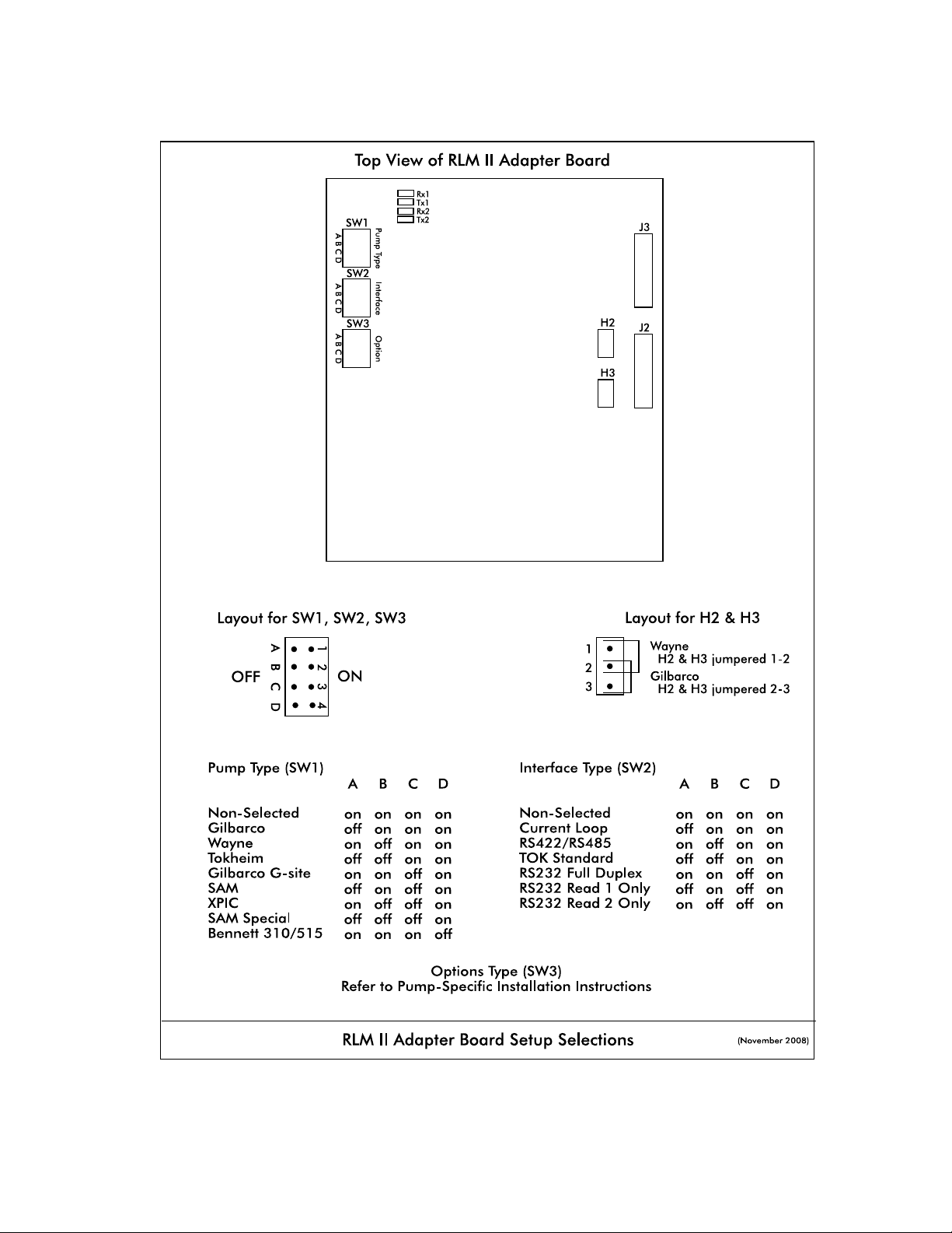
Diagram: RLM II Adapter BoardSetup Selections
RLM Systems Installation Guide Version 3.0 © November 2008
6
Page 13

RLM II for ELECTRONIC DISPENSERS
Dispenser Specific Installation
RLM II for Bennett 310/515 Systems
Note all warnings at the beginning of installation section.
Following the instructions in RLM II General Installation, perform general installation
procedure and the preliminary test procedure using Tester/WinTester program.
Proceed with RLM II installation, referencing Diagram: RLM II Adapter Board Jumper
Selections in the preceding section — RLM II for Electronic Dispensers, General Installation.
1. Set switch position SW1of Adapter Board for Bennett 310/515 models.
2. Set switch position SW2 of the Adapter Board for RS232 full duplex. Plug adapter
harness onto position J3.
3. Referencing the Bennett 310/515 installation manual, locate port 3 on Bennett
310/515. Connect the RLM II to the Bennett 310/515 using the PIE 9000 15 0040
cable and the RJ45 adapters PIE 9000 16 3004 and PIE 9000 16 3003. If the G-
SITE is using the C2 style controller, both adapters will be required. If the G-SITE is a
486-style controller, adapter PIE 9000 16 0002 will not be needed. Reference
Diagram: RLM II to Bennett 310/515 at the end of this section.
4. Return to the RLM II Installation Section for remaining system installation procedures.
RLM Systems Installation Guide Version 3.0 © November 2008
7
Page 14
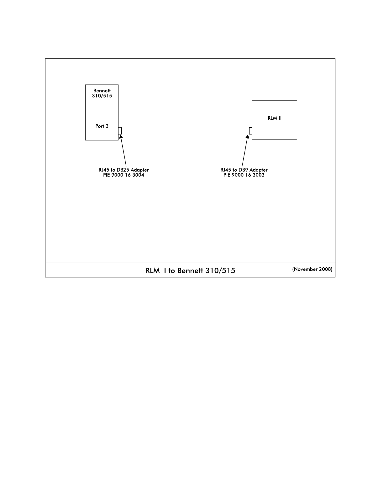
Diagram: RLM II to Bennett 310/515
RLM Systems Installation Guide Version 3.0 © November 2008
8
Page 15

RLM II for ELECTRONIC DISPENSERS
Dispenser Specific Installation
RLM II for Gilbarco Electronic Dispenser
Note System Warnings in the Systems Installation section.
Gilbarco MOC (major oil company) G-SITE Systems are a special configuration. For
Gilbarco MOC instructions and installation requirements, refer to RLM II for Gilbarco G-SITE
Installation.
Following the instructions in RLM II General Installation, perform general installation
procedure and the preliminary test procedure using Tester/WinTester program. Then, follow
specific instructions for connecting the RLM II system to the appropriate Gilbarco distribution
box (DBox). See Table: Gilbarco DBoxes at the end of this section.
Proceed with RLM II installation, referencing Diagram: RLM II Adapter Board Jumper
Selections in the preceding section — RLM II for Electronic Dispensers, General Installation.
1. Set switch on position SW1 of RLM II Adapter Board for all Gilbarco models.
2. If the Gilbarco system employs a current loop style Universal DBox or a TS1000
DBox, set switch on position SW2 of the Adapter Board for current loop. Plug the
adapter harness into position J2. Disconnect the Gilbarco console/controller from the
distribution box and connect the Gilbarco style RLM II adapter cable (PIE 9000 15
3027) to the Gilbarco DBox. Plug the long end of the adapter cable into the RLM II
DB9P connector on the end of the RLM II. Reference Diagram: RLM II to Gilbarco
DBox Universal/TS1000 later in this section.
If the Gilbarco system employs an RS422 style Universal DBox, set position SW2 of
the Adapter Board to RS422/RS485. Plug the adapter harness into position J3.
Disconnect the Gilbarco console/controller from the DBox and connect the Gilbarco
style RLM II adapter cable (PIE 9000 15 3036) to the Gilbarco DBox. Plug the long
end of the adapter cable into the RLM DB9P connector on the end of the RLM II.
Reference Diagram: RLM II to Gilbarco DBox Universal/TS1000 later in this section.
If the Gilbarco system employs a PA01330000 DBox, set position SW2 of the
Adapter Board for current loop. Plug the adapter harness into position J2. Cut off the
‘T’ end of the RLM II adapter cable (PIE 9000 15 3027). Locate an unused position
in the Gilbarco DBox and ensure that the switch is in the ‘Isolate’ position. Connect
the cut end to the Gilbarco DBox at this position. At this point, move the switch to the
’Normal’ position. In the event that the DBox positions are all in use, wire the RLM II
adapter cable in series with an existing dispenser.
RLM Systems Installation Guide Version 3.0 © November 2008
9
Page 16
Reference Diagram: RLM II to Gilbarco DBox PA01330000.
If the Gilbarco system employs a PA03060020 DBox, set switch position SW2 of the
Adapter Board for current loop. Using connectors PIE 9000 16 0004 and PIE 9000
16 0005 (supplied by Progressive), plug the adapter harness into position J2.
Disconnect the Gilbarco console/controller from the distribution box. Attach the DB9
to RJ45 adapters (supplied by PIE) to the ends of the RLM II adapter cable (PIE 9000
15 3097). Connect the RJ45 cable from the Gilbarco console/controller to one of
the RJ45 adapters. Using PIE supplied RJ45 cable 9000 15 0040, connect one end
to the Gilbarco DBox and the other end to the other RJ45 adapter. Reference
Diagram: RLM II to Gilbarco DBox PA03060000 following this section.
3. Return to the RLM II General Installation for remaining system installation procedures.
Table: Gilbarco DBoxes
Gilbarco dispensing systems use several types of distribution boxes. This table of DBox part numbers
with descriptions will assist you in determining which connection method to the RLM II meets your
requirements. Gilbarco uses two different electrical means of transmitting data — current loop and
RS422. It is very important to determine this prior to installing the RLM II.
DBox Part # Description
PA01330000 Old style DBox with circular DINN connector (current loop)
PA0261x000010 Universal DBox with DB9P male (current loop) — one board
PA0261x000020 Universal DBox with DB9P male (current loop) — two boards
PA0261x000011 Universal DBox with DB9S female (RS422) — one board
PA0261x000021 Universal DBox with DB9S female (RS422) — two boards
1
1
1
1
PA03060020 G-SITE DBox with RJ45 connector (current loop)
PA0242 TS1000 DBox with DB9P connector (current loop)
2
1 The Gilbarco Universal DBox may be configured as a one or two board unit, depending on the
fuel site dispensing equipment layout. If two boards and two inputs are used, multiple RLM IIs
are required for dispenser control. Refer to Gilbarco document number MDE-2713 for detailed
information on this product.
2 Refer to Gilbarco document number MDE-2381A or MDE-2382A for detailed information on this
product.
RLM Systems Installation Guide Version 3.0 © November 2008
10
Page 17
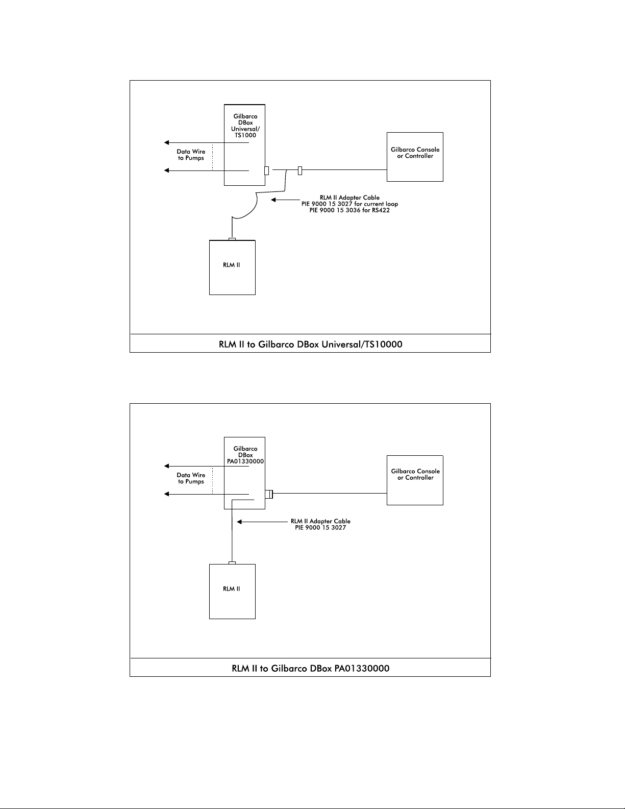
Diagram: RLM II to Gilbarco DBox Universal/TS1000
Diagram: RLM II to Gilbarco DBox PA01330000
RLM Systems Installation Guide Version 3.0 © November 2008
11
Page 18
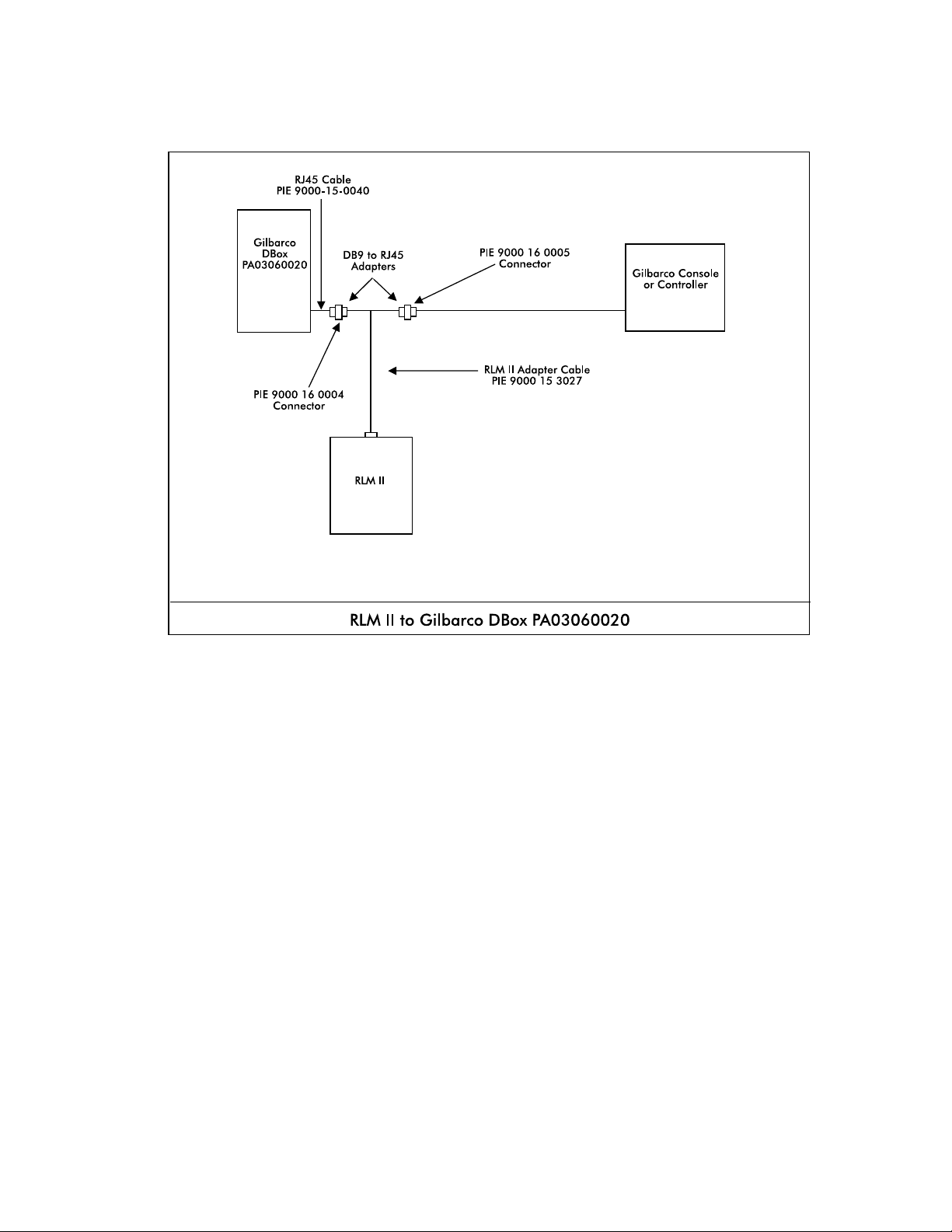
Diagram: RLM II to Gilbarco DBox PA03060020
RLM Systems Installation Guide Version 3.0 © November 2008
12
Page 19

RLM II for ELECTRONIC DISPENSERS
Dispenser Specific Installation
RLM II for Gilbarco MOC G-SITE Systems
Note all warnings at the beginning of installation section.
If the Gilbarco system employs a MOC G-SITE point of sale system, special procedures must
be followed to ensure a successful installation of the RLM II. First, it is important to know
from the site survey which type of controller (C2, 486, Pentium, etc.) the G-SITE is using.
Second, the revision number of the software running on the G-SITE is very important to know.
Confirm that the G-SITE will support the EMC tank monitoring option which is a component
of the BIR (Business Inventory Reconciliation) interface. The software revision number, along
with MOC type, indicate the ability of the G-SITE to support this function. If it is determined
that the G-SITE does not have the correct revision software loaded, a software update is
required from an authorized Gilbarco distributer. If it is determined that the G-SITE is EMC
ready, proceed with RLM II installation. Otherwise, contact dealer for further assistance.
Following the instructions in RLM II General Installation, perform general installation
procedure and the preliminary test procedure using Tester/WinTester program.
Proceed with RLM II installation, referencing Diagram: RLM II Adapter Board Jumper
Selections in the preceding section — RLM II for Electronic Dispensers, General Installation.
1. Set switch position SW1of Adapter Board for Gilbarco G-Site models.
2. Set switch position SW2 of the Adapter Board for RS232 full duplex. Plug adapter
harness onto position J3.
3. Referencing the G-SITE installation manual, locate the G-SITE controller EMC tank
monitor port. Connect the RLM II to the G-site using the PIE 9000 15 0040 cable
and the RJ45 adapters PIE 9000 16 0002 and PIE 9000 16 3003. If the G-SITE is
using the C2 style controller, both adapters will be required. If the G-SITE is a 486style controller, adapter PIE 9000 16 0002 will not be needed. Reference Diagram:
RLM II to Gilbarco C2 G-SITE and Diagram: RLM II to Gilbarco 486 G-SITE at the
end of this section.
4. Return to the RLM II Installation Section for remaining system installation procedures.
The RLM II G-SITE reports all totals by meter number for each fueling position. Blender
dispensers will report meter 1 to hose 1 and meter 2 to hose 2 position on the RLM II. A
blended product will report an increase for both meters.
RLM Systems Installation Guide Version 3.0 © November 2008
13
Page 20
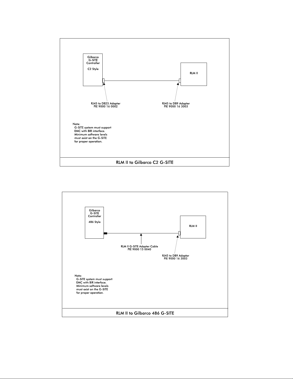
Diagram: RLM II to Gilbarco C2 G-SITE
Diagram: RLM II to Gilbarco 486 G-SITE
RLM Systems Installation Guide Version 3.0 © November 2008
14
Page 21

RLM II for ELECTRONIC DISPENSERS
Dispenser Specific Installation
RLM II for Wayne/Dresser Electronic Dispenser
Note all warnings at the beginning of installation section.
Following the instructions in RLM II General Installation, perform general installation
procedure and the preliminary test procedure using Tester/WinTester program.
Proceed with RLM II installation, referencing Diagram: RLM II Adapter Board Jumper
Selections in the preceding section — RLM II for Electronic Dispensers, General Installation.
1. Set switch position SW1 of Adapter Board for Wayne models.
2. On the Adapter Board, set switch position SW2 for current loop.
3. Set jumpers on positions H2 and H3 for Wayne models.
4. Plug adapter harness into position J2 on Adapter Board.
5. Plug the adapter cable, PIE 9000 15 3012, into the adapter port on the RLM II.
6. Locate the Wayne/Dresser distribution box and wire the other end of the adapter cable
into the unused dispenser positions in the DBox. In the event that the DBox is full, wire
in “series” with existing dispenser. The following chart shows wire color to function.
Wire Color Function
Black Loop 1 Red Loop 1 +
Green Loop 2 White Loop 2 +
7. On Wayne/Dresser DBoxes with dispensers wired into one side of the DBox board,
only one loop needs to be connected. Refer to Diagram: Wayne/Dresser DBox RLM
II Connection Example. For units with both sides of the DBox board wired, Loop 1
and Loop 2 must both be connected. Refer to Diagram: RLM II to Wayne/Dresser —
Typical Installation for installation in which 2 loops are needed.
RLM Systems Installation Guide Version 3.0 © November 2008
15
Page 22
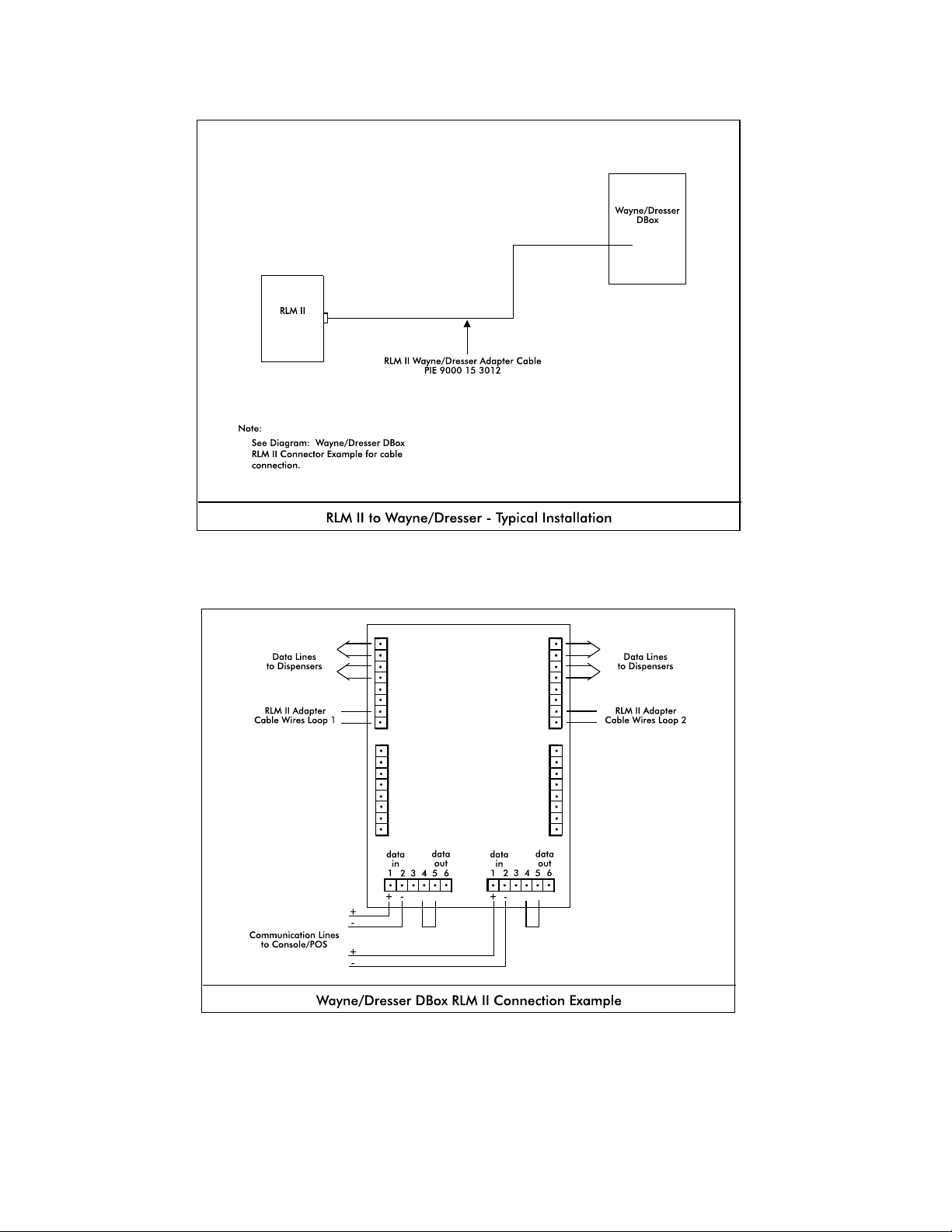
Diagram: RLM II to Wayne/Dresser — Typical Installation
Diagram: Wayne/Dresser DBox RLM II Connection Example
RLM Systems Installation Guide Version 3.0 © November 2008
16
Page 23

Special Start-Up Procedure for RLM II with Wayne/Dresser Dispensers
Recent RLM software modifications enable its use with the new line factor values utilized by
Wayne/Dresser dispensers.
Line factors are necessary for calculating the final volumes for each transaction. The RLM II
gathers line factors from the data communications line. If no line factors are detected by the
RLM, all sales for that fueling position will be zero.
Line factors are sent from the dispenser to the controlling console only when requested.
Some consoles only request the line factor upon console power start-up. In this case, the
request for line factor may be forced by breaking the data loop to the dispensers, waiting 15
seconds, and then restoring the loop.
The RLM II software reports a BUSY status for a fueling position if the RLM II has not detected
and stored the line factor. (This is easily demonstrated with our diagnostic utility TESTER or
WINTESTR, or the RLM II’s built-in diagnostics.) As discussed above, if a fueling position
status is reported as BUSY, with no sale in progress, the console can be forced to request the
line factor by breaking the loop and restoring it. Repeat procedure until all BUSY statuses are
gone. Once the RLM II has detected the line factor for a fueling position, it is stored in nonvolatile memory. The following should be noted:
C The console should only be forced to report line factors when no sales are in progress.
C Wayne/Dresser DBoxes have two data loops — be sure to force the retry on the
correct data loop.
C Another indicator of a missing line factor is a situation in which all sales for a fueling
position register zero.
RLM Systems Installation Guide Version 3.0 © November 2008
17
Page 24

RLM II for ELECTRONIC DISPENSERS
Dispenser Specific Installation
RLM II for Tokheim Electronic Dispenser
Note all warnings at the beginning of installation section.
Following the instructions in RLM II General Installation, perform general installation
procedure and the preliminary test procedure using Tester/WinTester program.
Proceed with RLM II installation, referencing Diagram: RLM II Adapter Board Jumper
Selections in the preceding section — RLM II for Electronic Dispensers, General Installation.
1. Set switch position SW1 of Adapter Board for Tokheim models.
2. Determine the type of electrical communications used by the Tokheim system. Match
the RLM II with the Tokheim system by making the corresponding switch selection on
SW2 of the Adapter Board. For Tokheim M98 and M94 Power Centers or 67
DBoxes, make the Tokheim Standard selection. For the 67B DBox, make the
RS422/RS485 selection on SW2. Note that communication for the 67 and 67B
DBoxes can be modified in the field, so that model number may not accurately reflect
the communication method. Contact the Tokheim service company responsible for site
service to confirm DBox settings.
3. Connect adapter cable:
C Standard Tokheim — Plug adapter cable, PIE 9000 15 3011, into position J2
of the Adapter Board.
C RS422/RS485 — Plug adapter cable, PIE 9000 15 3011, into position J3 of
the Adapter Board.
4. Locate the round black connectors on the existing console to DBox cable. Disconnect
the existing console/controller cable from the Tokheim M98/M94 Power Center, the
67 DBox, or the 67B DBox. Attach the RLM II adapter cable to the cable ends from
the console/controller and from the DBox/power center. Refer Diagram: RLM II for
Tokheim — Typical Installation.
RLM Systems Installation Guide Version 3.0 © November 2008
18
Page 25
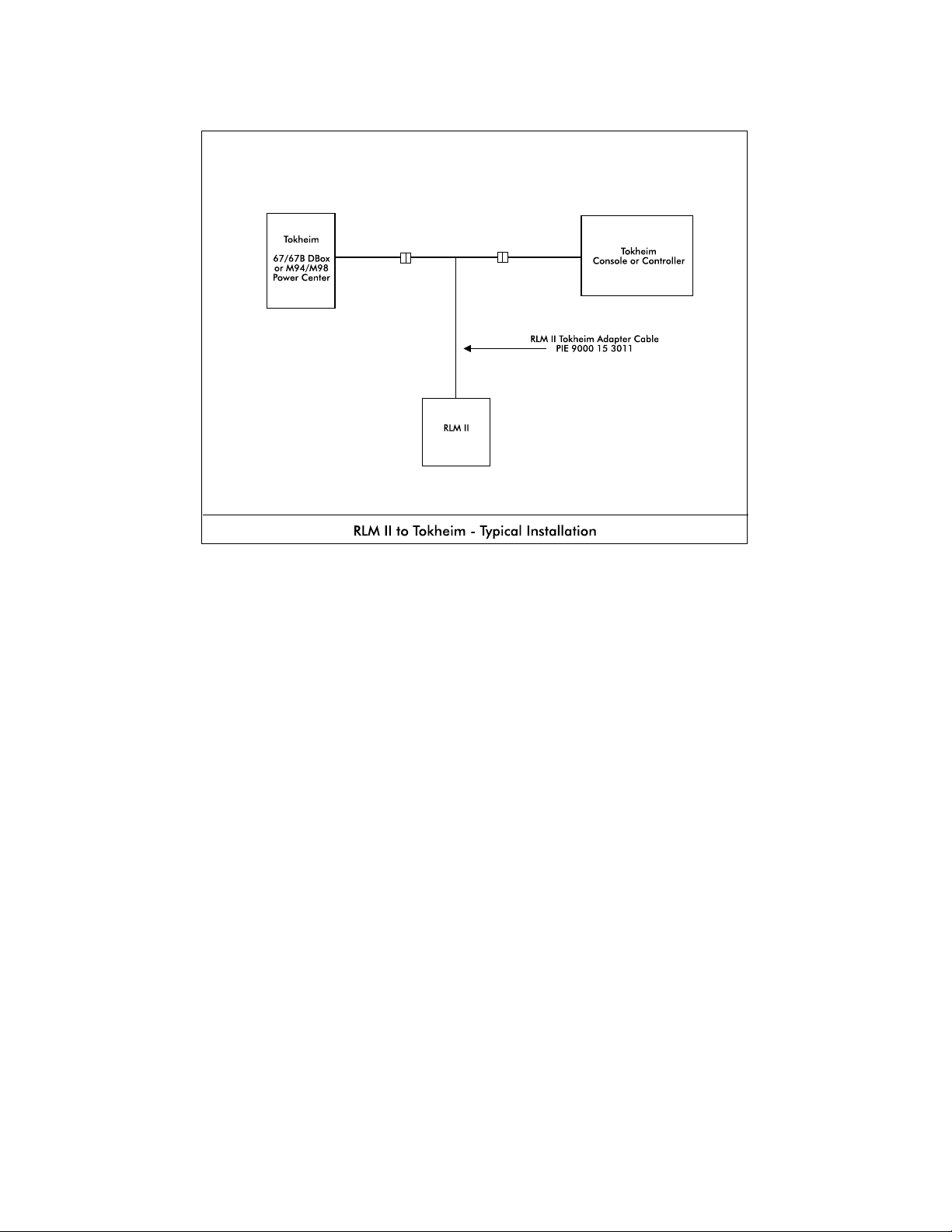
Diagram: RLM II to Tokheim — Typical Installation
RLM Systems Installation Guide Version 3.0 © November 2008
19
Page 26
RLM II for ELECTRONIC DISPENSERS
Diagnostics
Features and Operation of the RLM II Diagnostic Port
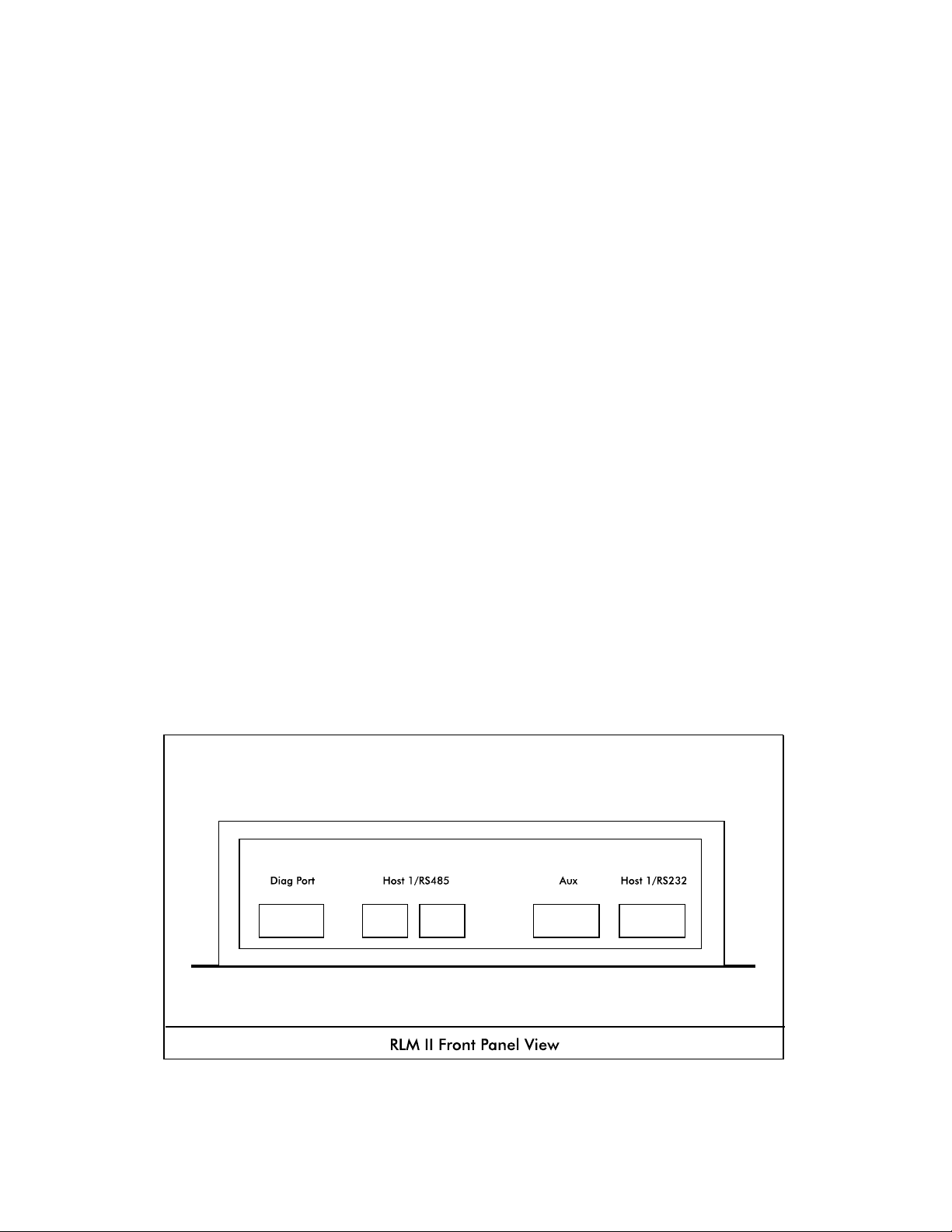
Extensive testing and data collection is available to the user through the RLM II’s built-in
diagnostic port, which is physically located on the front panel of the RLM II. See Diagram:
RLM II Front Panel below. Accessing the diagnostic port requires a computer running a
terminal emulation program such as Hyperterm or Procomm. Physical connection is made
using a serial cable (straight through). Once the connection is established, power up the
RLM II and a prompt will appear. To view a help menu, type a ? at the prompt.
The terminal emulation program (Hyperterm or Procomm) must be set to the following
parameters to work properly.
Baud rate 57,600
Data bits 8
Parity none
Stop bits 1
Flow control none
Terminal emulation
setting
ANSI
RLM Systems Installation Guide Version 3.0 © November 2008
20
Page 27
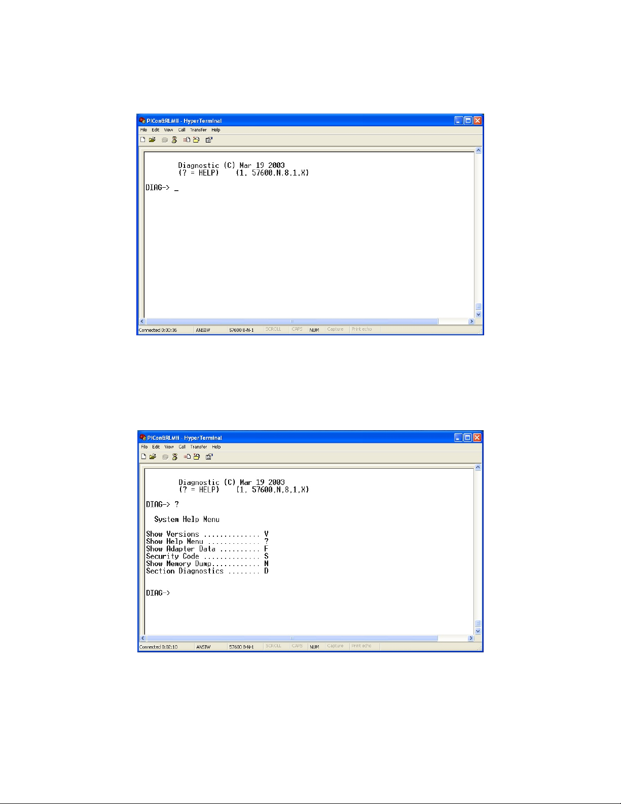
RLM II Power Up
When the RLM II powers up, the screen below will appear.
RLM II Help Menu (?)
The screen below shows the help menu. To display a menu of available options, simply
type ? at any of the prompts.
RLM Systems Installation Guide Version 3.0 © November 2008
21
Page 28
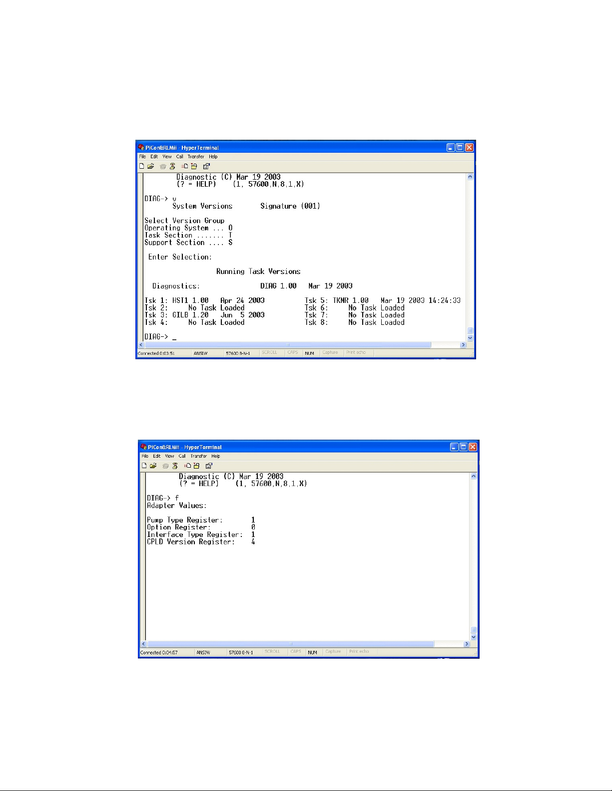
View All RLM II Software Versions (V)
The V option may be used to view all software versions loaded into the RLM II, as
demonstrated on the screen below. A second V entry is required to display the section
versions. The screen below is an example showing the Task Section versions.
RLM II Settings (F)
The F option displays the settings on the adapter board, as shown on the screen below.
RLM II Section Diagnostics (D)
RLM Systems Installation Guide Version 3.0 © November 2008
22
Page 29
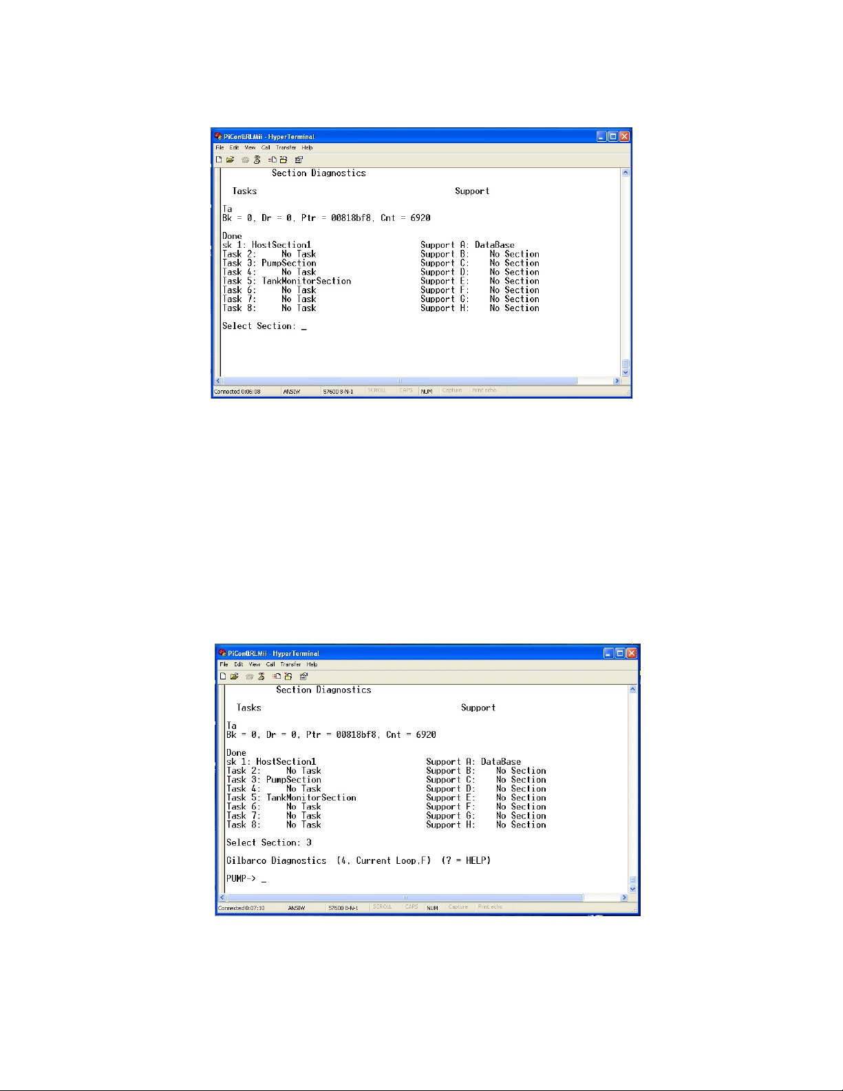
The D option displays Section Diagnostics, as shown below. From here, each section of
the RLM II may be accessed to perform extended diagnostics.
Extended Section Diagnostics
Extended diagnostics may be accessed by entering the number corresponding to the task to
be viewed. For example, on a screen as shown below, entering 3 will access
DispenserSection diagnostics. As shown below, the screen displays the dispenser
configuration information. This allows the user to check adapter settings on the RLM II.
From here, other tests, such as monitoring the dispenser port data, are available.
RLM Systems Installation Guide Version 3.0 © November 2008
23
Page 30
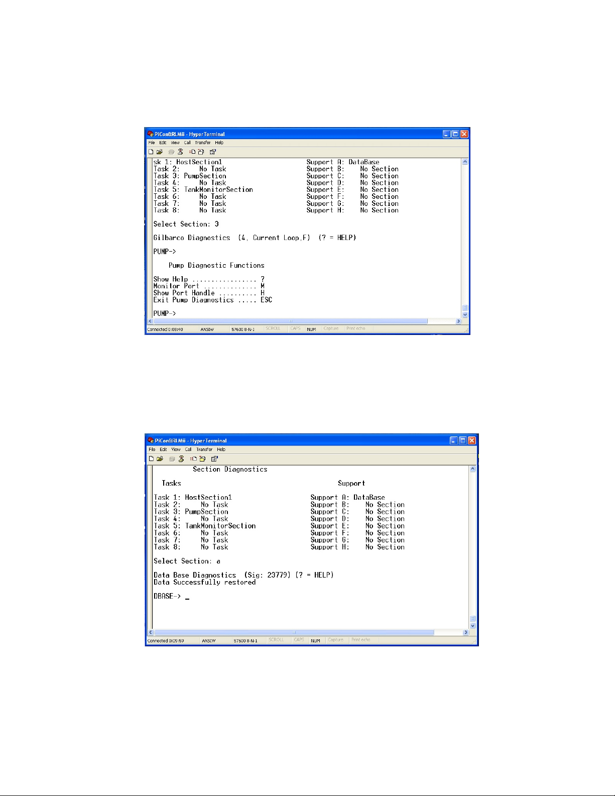
RLM II Diagnostic Function Options at Any Prompt Level (?)
At any prompt level a ? can be typed to show the available diagnostic funtion options, as
shown on the screen below.
Example — RLM II Section Diagnostics
Below is another example of section diagnostics. This example is for DataBase, which is
accessed by simply pressing A at the section diagnostics menu.
Example — Displaying Specific Set of Data from RLM II Database Section
RLM Systems Installation Guide Version 3.0 © November 2008
24
Page 31
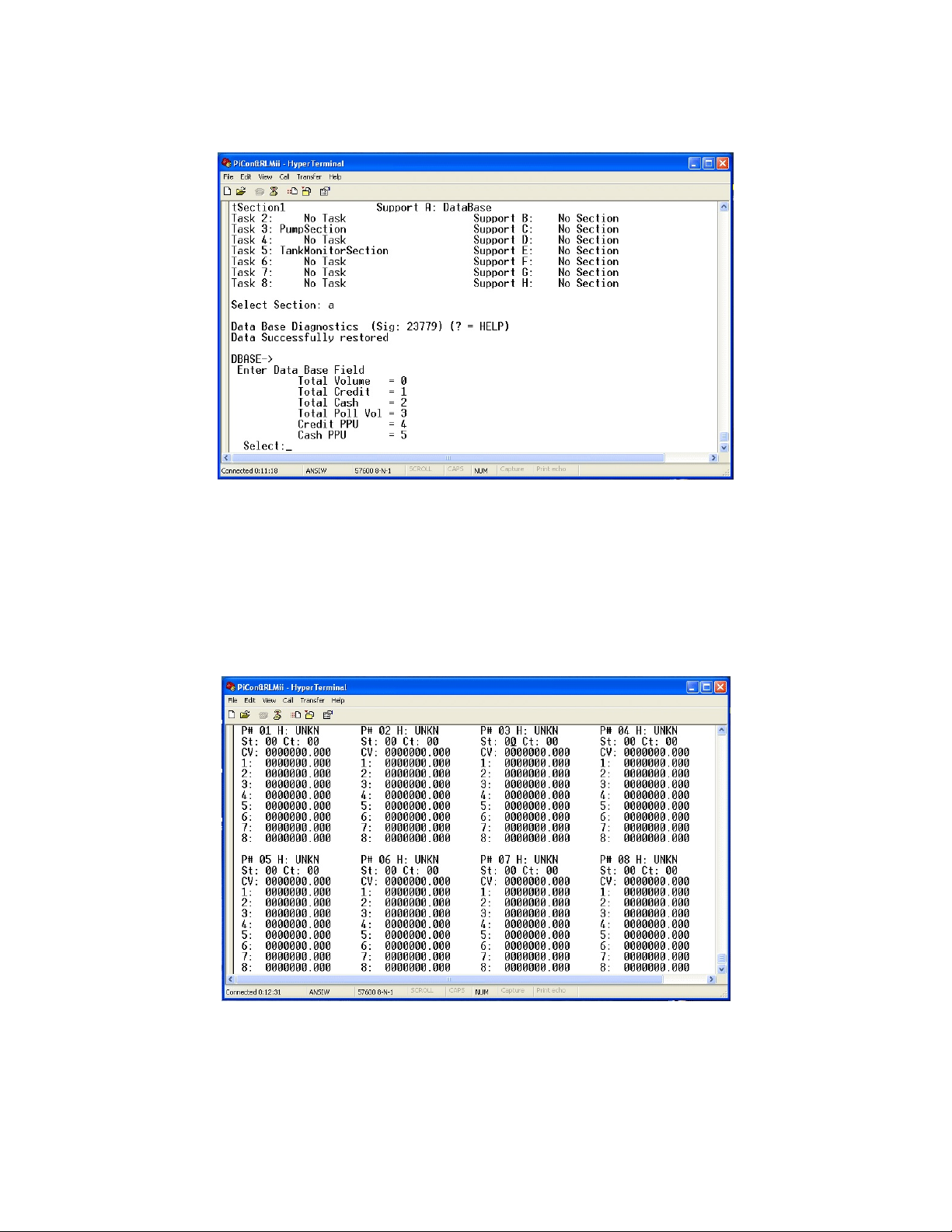
As shown on the screen below, the prompt is asking which set of data to display. Selecting
0 takes the user to the Total Volume screen.
Example — RLM II Total Volumes Screen
The screen below shows all the volume hose totals for dispensers 1-8. Pressing the letter N
will scroll the display through the next eight dispensers, etc. Remember, at any level
entering a ? will access the help menu.
RLM II for ELECTRONIC DISPENSERS
Diagnostics
RLM Systems Installation Guide Version 3.0 © November 2008
25
Page 32

Testing the RLM II Using Tester/WinTester
PIE provides two software diagnostic tools on its website (www.pie-corp.com), "Tester" and
"WinTester." Tester is a DOS-based utility, while WinTester is a Windows-based program
designed to run on Win 95, Win 98, Win ME, Win 2000 and XP.
Either Tester or WinTester:
! Allows the user to retrieve data from the RLM II.
! Has a reset feature which clears all totals in the RLM II and a test load to determine
the RLM II's storage ability.
! Has the ability to run the comm port on the PC to coordinate the jumper settings of
the RLM II and the PC.
Testing the RLM II with "Tester" Utility
1. Check to ensure that your computer has the ANSI.SYS driver loaded on the root
directory on C drive. Your CONFIG.SYS file should have a statement such as
device=c:\[path]\ansi.sys. If not, locate the ANSI.SYS file on your computer and edit
your CONFIG.SYS file to include the device=c:\[path]\ansi.sys statement. If this
driver is not loaded properly, the screen will not be readable when Tester is loaded.
Load the Tester program. Go to location program was downloaded and run by typing
Tester.
2. Determine the communication settings in the RLM II from the jumper settings (i.e.,
baud rate=9600, data bits=8, stop bits=1, parity=N, RTS=+, device address=00).
Connect your PC to the host port on the front panel of the RLM II.
3. Follow the prompts on the screen, setting Tester's parameters to match those of the
RLM II.
4. The screen will fill with eight fueling positions with dispenser totals information. If data
appears scrambled on the screen, press E to exit and recheck to make sure ANSI.SYS is
loaded. These totals represent the transactions the RLM II has captured since it was
last reset.
RLM Systems Installation Guide Version 3.0 © November 2008
26
Page 33

Press T to view the next 8 positions, 9 through 16.
Press ? at any time to view a menu of the Tester commands.
To test the RLM II serial comm port with Tester, follow 1-5 above and #6 below.
5. RLM II Is shipped from PIE will have all totals cleared. To test load an RLM II and to
ensure the communications link between the Tester program and the RLM II, press L
and look at Dispenser2 Hose2 position on the screen. It should read "1234567890".
To reset the RLM II and clear all data, press R. All totals cells will show zeroes. Check
to make sure that the status message at the top of each dispenser display reads "OK".
See note at end of this section.
Testing the RLM II with the "WinTester" Utility
1. Go to location program was downloaded and run by typing WinTester.
2. Determine the communication settings in the RLM II from the jumper settings (i.e.,
baud rate=9600, data bits=8, stop bits=1, parity=N, RTS=+, device address=00).
Connect your PC to the host port on the front panel of the RLM II.
3. Using the Setup and Select pulldown menus on the screen, set WinTester's parameters
to match the RLM II.
4. The screen will fill with eight fueling positions with dispenser totals information. These
totals represent the transactions the RLM II has captured since it was last reset.
An on-screen display of stats for each fueling position is a component of the testing procedure
when using either the Tester or WinTester utility. The status of each fueling position will be
indicated as one of the following:
OK
TO time out
CS "check sum" error
Status for all fueling positions should read OK before proceeding with test program.
RLM Systems Installation Guide Version 3.0 © November 2008
27
Page 34

RLM II for ELECTRONIC DISPENSERS
Diagnostics
Troubleshooting
PROBLEM ANALYSIS/RECOMMENDATION
RLM II does not talk to tank monitor. Run Tester or WinTester utility.
RLM II does not talk to Tester or
WinTester. See Testing the RLM II Using
Tester/WinTester section.
! Check jumper settings on RLM II. Refer to Diagram: RLM II Adapter Board Jumper
Selections.
Baud correct?
Parity correct?
Stop bits correct?
Data bits correct?
Device address correct?
! Check power indicator on RLM II main board.
! Check PC.
Comm port on PC OK?
RS232 cable plugged into PC?
! Port parameters set correctly on Tester/ WinTester?
! Ensure that PC is plugged into host port of RLM II
RLM II does not capture any data. ! Ensure that LED on adapter board is flashing.
! Refer to dispenser specific diagnostics section to make sure connections are correct.
! Check software version in RLM II to make sure it is latest rev.
! Check to ensure there are no console to dispenser connection errors.
! Contact dealer for assistance.
RLM II data does not match dispenser
totals exactly.
RLM Systems Installation Guide Version 3.0 © November 2008
! Make sure all dispensers are idle at beginning and end of totals test.
! Make sure there are no console (POS) to dispenser connection errors.
! Make sure RLM II software version is current.
! Contact dealer for assistance.
28
Page 35

RLM II for ELECTRONIC DISPENSERS
Diagnostics
Dispenser-Specific Troubleshooting
GILBARCO
PROBLEM ANALYSIS/RECOMMENDATION
LED (D5) is off and never flashes. Console/POS not communicating with dispensers.
LED (D5) is on solid. ! Adapter cable connected incorrectly.
! Wrong type adapter communications input used — RS422 or current loop. Refer to
Diagram: RLM II Adapter Board Switch Selections.
! Defective cable.
All communications down on console/POS
to dispensers.
PROBLEM ANALYSIS/RECOMMENDATION
No data capture. ! Is EMC port on G-SITE enabled?
RLM II-GS not answering G-SITE.
! Adapter cable not connected.
! Adapter cable connected incorrectly.
! Wrong type adapter communications input used — RS422/current loop.
Refer to Dispenser Specific Installation, RLM II for Gilbarco Electronic Dispenser
section.
! Defective cable.
GILBARCO MOC G-SITE
! Is correct software version being used on G-SITE?
! Is adapter cable plugged into correct port on G-SITE?
! Is correct type of adapter being used?
Refer to Diagram: RLM II Adapter Board Switch Selections.
Are setting correct on the adapter board? Refer to Diagram: RLM II Adapter Board Switch
Selections for proper jumper selections.
RLM Systems Installation Guide Version 3.0 © November 2008
29
Page 36

TOKHEIM
PROBLEM ANALYSIS/RECOMMENDATION
Console to dispenser
communication shuts down when
adapter cable is connected.
LEDs are off and never flash. ! Test twist-lock connectors for tightness.
Only one LED is flashing (D2 or
D3).
PROBLEM RECOMMENDATION
Data is not captured correctly for
one or more of the dispensers .
Is adapter cable connected correctly? Refer to Dispenser Specific Installation, RLM II for
Tokheim Electronic Dispenser section.
! Ensure that adapter cable is connected correctly.
! Ensure that correct adapter communications input is used — RS422/standard.
Refer to Diagram: RLM II Adapter Board Switch Selections.
! Defective cable.
Check all cable connections.
WAYNE/DRESSER
! Ensure that both loops on adapter cable at position J2 of adapter board are wired correctly.
! Check normal/bypass switch. Is it in Normal?
See Diagram: Wayne/Dresser DBox RLM Connection Example.
Console to dispenser
communication shuts down when
adapter cable is connected.
LEDs not flashing. ! Make sure both loops on adapter cable at J2 are wired correctly.
RLM Systems Installation Guide Version 3.0 © November 2008
! Adapter cable (should be at position J2) may be connected incorrectly.
! Loop wires in DBox may be wired incorrectly. See Diagram: Wayne/Dresser DBox RLM
II-W Connection Example.
! Adapter cable may be connected incorrectly.
! Wrong dispenser type may be selected.
! Check normal/bypass switch. Is it in Normal? Refer to Diagram: RLM II Adapter Board
Jumper Selections and Diagram: Wayne/Dresser DBox RLM II Connection Example.
30
Page 37

RLM MECH for MECHANICAL DISPENSERS
General Installation
Read System Installation section, as well as this entire section of installation manual before
attempting to install the RLM Mech. Note System Installation Warnings in System
Installation section. Referring to Diagram: RLM Mech Connector/Jumper Layout in this
section, proceed with RLM Mech installation.
1. A junction box with a single receptacle outlet must be provided. See RLM Mech Power
Requirements listed below.
RLM Mech Power Requirements
The RLM Mech must be powered from a dedicated 115 VAC single circuit breaker, with no other devices
connected to wire or breaker. Do not use a switched neutral breaker. The neutral must come directly
from the neutral bus in the electric supply panel. No other neutral circuits may be connected to this wire.
The electric supply system earth bond must connect to a driven ground rod or other earth bonding
systems that comply with the National Electrical Code, Article 250.
2. Securely mount the RLM Mech main box in a nonhazardous location according to the
suggested layout in the tank monitor installation instructions.
3. Set all jumpers on the RLM Mech main board according to the specific application
requirements. These settings affect the tank monitor communications parameters such
as baud rate, parity, data bits and device addressing. Also, these jumpers allow the
RLM Mech to be configured for daisy-chaining together using, RS485 multi-drop
circuitry.
4. Mount pulsers on volume shaft of mechanical dispenser computer.
5. Identify unused switch in electric reset for use as a return switch on the RLM Mech.
6. Wire the pulsers and motor return (MR) switches to the RLM Mech.
7. Connect a PC to the installed RLM Mech’s communication cable.
8. Plug the wall transformer into the dedicated power outlet to apply power to the RLM
Mech system.
9. Run Tester Program supplied on the system diskette shipped with the RLM Mech, and
perform a preliminary test. Refer to Testing the RLM II Using Tester/WinTester in the
RLM II section of this manual.
10. Refer to Diagram: RLM Mech RS232 Cable Connector 5 Pinout when connecting to
tank monitor.
RLM Systems Installation Guide Version 3.0 © November 2008
31
Page 38
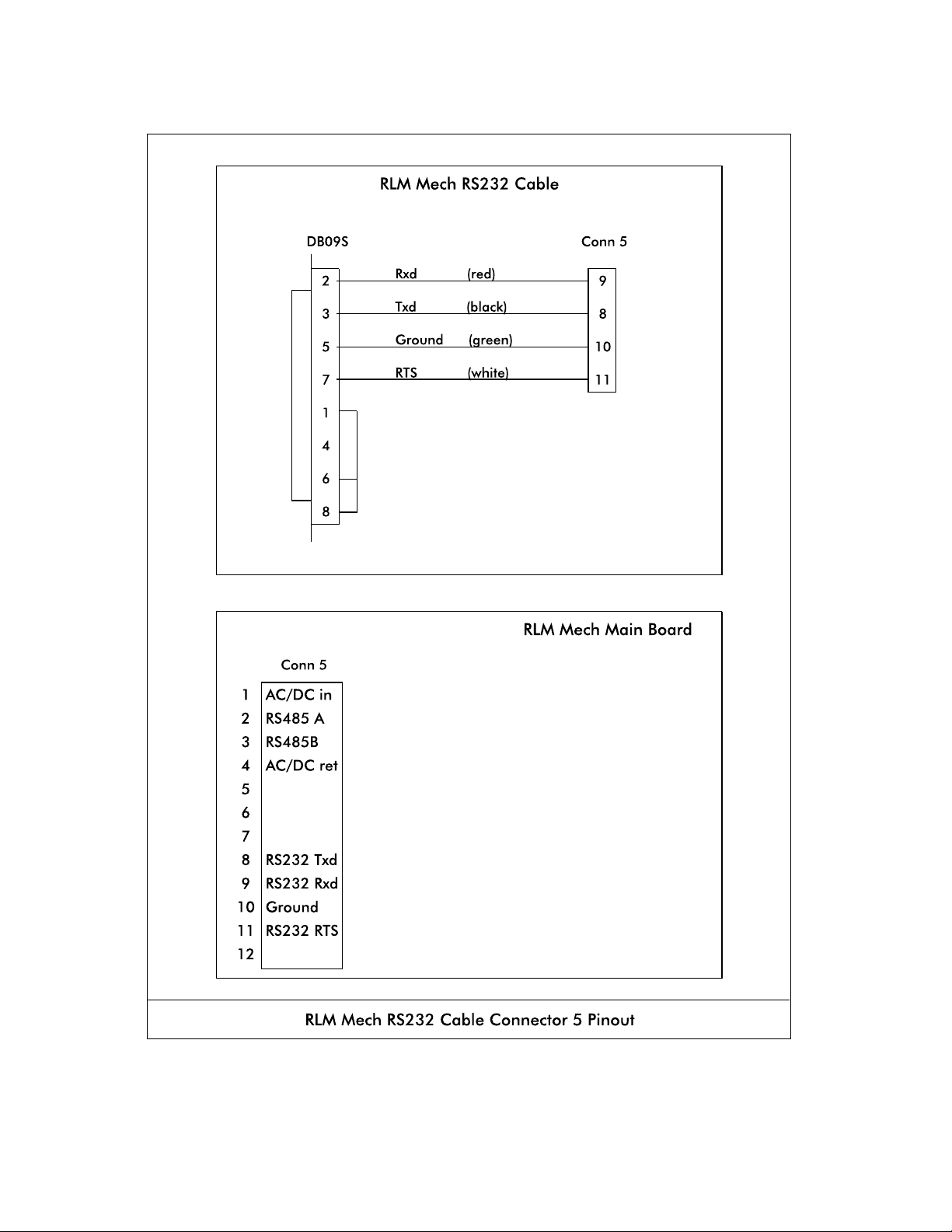
Diagram: RLM Mech RS232 Cable Connector 5 Pinout
RLM Systems Installation Guide Version 3.0 © November 2008
32
Page 39
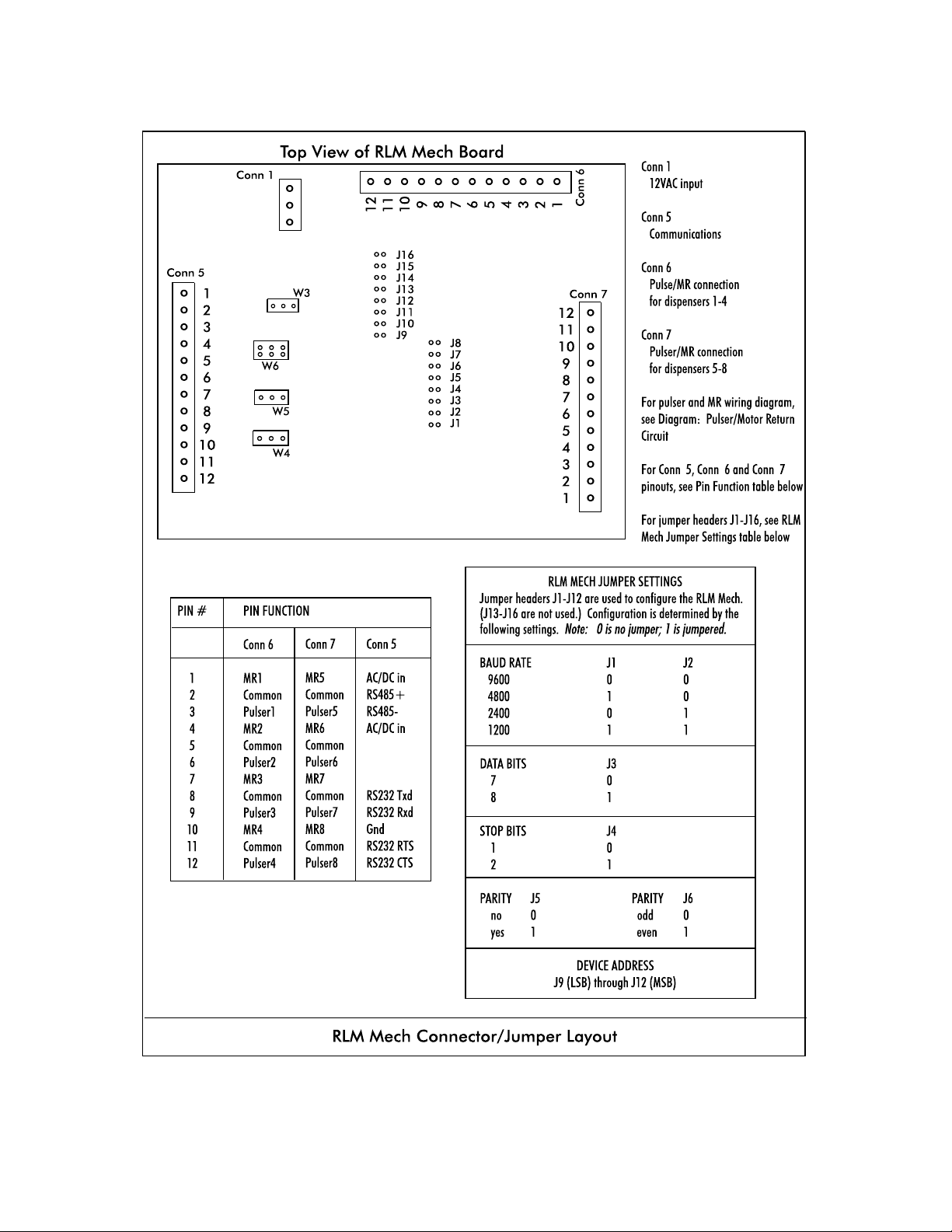
Diagram: RLM Mech Connector/Jumper Layout
RLM Systems Installation Guide Version 3.0 © November 2008
33
Page 40
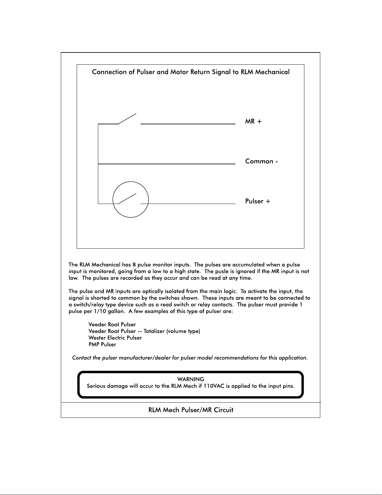
Diagram: Pulser/MR Circuit
RLM Systems Installation Guide Version 3.0 © November 2008
34
Page 41

RLM MECH for MECHANICAL DISPENSERS
Diagnostics
Testing the RLM Mech Using Tester/WinTester
To utilize Tester/WinTester, follow instructions as outlined in preceding section of manual:
RLM II for Electronic Dispensers, Diagnostics, Testing the RLM II Using Tester/WinTester.
RLM Systems Installation Guide Version 3.0 © November 2008
35
Page 42

RLM MECH FOR MECHANICAL DISPENSERS
Diagnostics
Troubleshooting
PROBLEM ANALYSIS/RECOMMENDATION
RLM does not talk to tank monitor. Run Tester or WinTester utility.
RLM Mech does not talk to Tester
or WinTester. See Testing the RLM
II Using Tester/WinTester in RLM II
section of manual.
RLM Mech does not capture any
data.
RLM Mech data does not match
dispenser totals exactly.
! Check jumper settings on RLM Mech. Refer to Diagram: RLM Mech Connector/ Jumper
Layout
Baud correct?
Parity correct?
Stop bits correct?
Data bits correct?
Device address correct?
! Check power indicator on RLM main board.
! Check PC.
Comm port on PC OK?
RS232 cable plugged into PC?
! Port parameters set correctly on Tester/ WinTester?
! Make sure return switch is wired (operating) correctly.
! Make sure wiring for pulser and return switches is correct.
! Make sure all dispensers are idle at beginning and end of totals test (snapshot).
! Check for defective pulser
! Make sure return switch is operating correctly.
Does not count on one or more
dispensers.
One or more dispensers miscount. ! Loose wire connection to pulser.
RLM Systems Installation Guide Version 3.0 © November 2008
! Check pulser operation.
! Check MR going active after dispenser reset cycle. (With volt meter set on a 10vdc scale,
place probes on MR line and common. With MR switch inactive — dispenser off —
meter should read approximately 8vdc. With MR switch active — dispenser running —
your meter should read approximately 0VDC.)
! Defective pulser.
! Defective mechanical computer.
! Check MR signal operation.
36
 Loading...