

Page 1

PIcon Console Controller
User Reference Manual
Page 2

1106 Great Falls Court, Suite G
Knightdale, NC 27545
Phone 919 266-4442 • Fax 919 266-4588
www.pie-corp.com
© Copyright 2006
Progressive International Electronics
Page 3

PICON CONSOLE CONTROLLER
User Reference Manual
CONTENTS
GENERAL INFORMATION & WARRANTY ...............................Page 1
General Information .........................................Page 1
PIcon Manufacturer's Warranty ..................................Page 3
INSTALLATION ..................................................Page 4
Introduction ...............................................Page 4
General Installation Guidelines .................................Page 5
Installation Warnings .........................................Page 6
QUICK STARTUP.................................................Page 7
Basic Startup Procedure .......................................Page 7
OPERATION ....................................................Page 8
Introduction ...............................................Page 8
Display and Status Indicators ..................................Page 10
Sales ...................................................Page 12
Special Select Functions......................................Page 14
PROGRAM & REPORT ............................................Page 17
Introduction ..............................................Page 17
PIN Code Access ..........................................Page 18
Manager Access ......................................Page 18
Operator Access......................................Page 18
Mode Descriptions .........................................Page 19
Mode 1 — Dispenser Setup Information . . . . . . . . . . . . . . . . . . . . . Page 19
Mode 2 — Product Information ...........................Page 21
Mode 3 — Beeper Settings ..............................Page 22
Mode 4 — Clock/Calendar ..............................Page 23
Mode 5 —Program Operator/Manger PIN Codes
............................................Page 24
Modes 6 - 9 are reserved. ...............................Page 24
Mode 10 — Read Reports ...............................Page 25
Mode 11 — Print Reports/Program Print Header
............................................Page 26
Mode 12 — Clear Resettable Totals . . . . . . . . . . . . . . . . . . . . . . . . Page 29
Mode 50 — Select Language ............................Page 29
Mode 51 — Select Dispenser Type . . . . . . . . . . . . . . . . . . . . . . . . . Page 30
Mode 60 — Pump Configuration . . . . . . . . . . . . . . . . . . . . . . . . . Page 30
Mode 70 — ATG Activation .............................Page 30
DIAGNOSTICS .................................................Page 31
PIcon Internal Diagnostics ....................................Page 31
Download Print Header .................................Page 32
Download Application..................................Page 33
Page 4

PATENTS
Progressive International Products are manufactured or sold under one or more of the
following U.S. patents.
5,790,410
5,831,861
5,694,326
5,663,887
5,557,529
5,394,336
5,361,216
5,270,943
5,108,742
HISTORY OF DOCUMENT REVISIONS
Rev. 1.0
Initial Release
Rev. 2.0
COPYRIGHT
Copyright © 2006 Progressive International Electronics, Inc. All rights reserved. No part of
this publication may be reproduced, stored in a retrieval system or transmitted, in any form or
by any means, electronic, mechanical, photocopying, recording, or otherwise, without the
prior written permission of Progressive International Electronics, Inc.
All brands or product names are trademarks or registered trademarks of their respective
companies.
Revision 2.0 (06/06)
Page 5
PIcon General Information & Warranty
GENERAL INFORMATION & WARRANTY
General Information
The PIcon is an economical, full-featured console designed to provide control of up to 16 fueling
positions. While most consoles can only control one type of fuel dispenser, the PIcon may be
configured to run any major brand electronic dispenser. This is accomplished through the use of
brand-specific Progressive International (PI) DBoxes that contain the unique circuitry required to
interface to each individual dispenser brand. An alternative to this solution is the use of
configurator boxes, supplied by PI, along with the dispenser manufacturer’s DBox.
Your PIcon provides full features, yet is very simple to install and operate. Due to meticulous
design of the keyboard and display layout, keystrokes are kept to a minimum during
programming setup and normal operation modes.
Standard features provided by the PIcon for efficient control of your fueling dispensers include:
C Full featured console which includes prepay/postpay, preset, drive-away alerts, stacked sale,
cash/credit operation.
C Management features including dispenser, shift and station totals, management security,
prices programmed by product.
C Easy to read LCD display.
C Register style keyswitch for efficient operator entry.
C Controls up to 16 fueling positions — including all major electronic dispensers and new
blending dispensers.
C Audible alerts for call, drive-away and collect.
C Memory backup to retain data in the event of power outage.
Rev 2.0 June 2006
Page 1
Page 6

PIcon General Information & Warranty
C Built-in hardware clock to time stamp all reports.
C Compact size allowing convenient counter-top positioning while utilizing a minimum
amount of valuable counter space.
C Standard printer interface for use with most low-cost printers.
C Ease of installation — console wires directly into dispenser distribution boxes or PI DBoxes.
Prior to installation or operation of the PIcon, please review each section of this manual and
other pertinent equipment manuals to familiarize yourself with the system.
Rev 2.0 June 2006
Page 2
Page 7

PIcon General Information & Warranty
PIcon Manufacturer's Warranty
Progressive International Electronics, Inc. (SELLER) warrants to the Purchaser of the PIcon fuel control equipment
manufactured by Seller against defects in material or workmanship for one (1) year from date of shipment. Seller
will replace or repair defective parts or replace and issue credits to the Purchaser's account in accordance with the
following Conditions of Warranty.
CONDITIONS OF WARRANTY
1. Credit will be applied only when the completed warranty request form and the defective parts are received and
inspected.
Decisions to repair or replace defective equipment are solely at the discretion or PIE.
2. When parts shipments are made prior to receiving the required warranty request and defective parts, they will be
billed to the Purchaser.
3. In all cases, approved warranty requests will be expedited by issuing the appropriate credit to the Purchaser's
account and shipping replacem ent parts.
4. Credits will not be issued for parts and no cash refunds for warranty credits will be made.
5. All components and parts must be returned to the factory prepaid, and in turn, replacement components and
parts will be returned prepaid by the factory.
6. Seller's warranty applies only if the equipment has been installed and used in accordance with Seller's
instructions. The warranty is void if any unauthorized alteration or addition has been made to the equipment or
if it has been subject to damage caused by abuse, misapplication, accident or improper operation.
7. The Seller's liability for any damages, including contribution and indemnification, arising out of or in any way
connected with the supplying of the equipment or its use, shall not in any case exceed the cost of repair of the
equipment as herein provided. Upon expiration of the warranty, all such liability, as well as any other liability,
shall terminate.
8. Nothing contained herein shall make the Purchaser, its agents or employees, an agent or representative of Seller
and Seller assumes no responsibility of any act, omission, representation or warranty by the Purchaser or anyone
else except as expressly stated herein.
9. The final Decision as to the validity of any claims arising under the warranty shall be determined solely by the
Seller.
THE FOREGOING WARRANTY IS IN LIEU OF ALL OTHER WARRANTIES, EXPRESSED OR IMPLIED,
INCLUDING, BUT NOT LIMITED TO, THE IMPLIED WARRANTIES OR MERCHANTABILITY AND
FITNESS FOR A PARTICULAR PURPOSE WHICH EXCEED THE AFORESAID OBLIGATIONS AND ARE
HEREBY DISCLAIMED AND EXCLUDED BY SELLER.
W A R N I N G
Warning: Installation m ust comply with the National Electrical Code, as well as Federal, State, Local and all
applicable codes.
Warning: High voltages are present in this equipment. Disconnect all power before making installation to prevent
personal injury or equipment damage.
Warning: Do not install PIcon units in a volatile, combustible or explosive atmosphere. All PIcon units must be
protected from severe vibration, extreme temperatures and excessive humidity.
Any peripheral equipment is to be installed over a non-hazardous location.
Any peripheral equipment connected to the PIcon must be UL listed and using standard RS232 or RS485
communication.
The PIcon must be plugged into a dedicated 115 VAC wall socket with bonded earth ground.
Rev 2.0 June 2006
Page 3
Page 8

PIcon Installation and Operation
INSTALLATION
Introduction
The Installation Section contains instructions for installing the PIcon to electronic fuel dispenser
computers.
Instructions for installing or servicing electronic fuel dispensers are not included in this manual.
(See manufacturer’s manual specific to each particular product for installation/servicing
instructions.)
Read the entire installation section of this manual before attempting to install the PIcon.
If further assistance is required, please contact your PIcon dealer.
Rev 2.0 June 2006
Page 4
Page 9
PIcon Installation and Operation
General Installation Guidelines
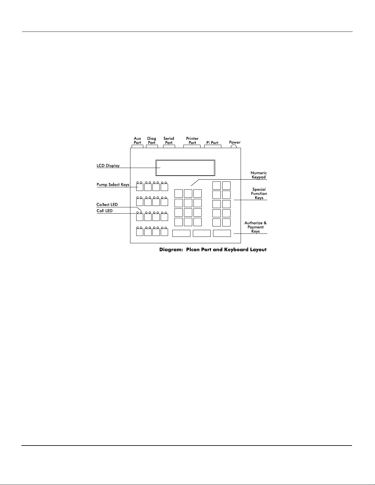
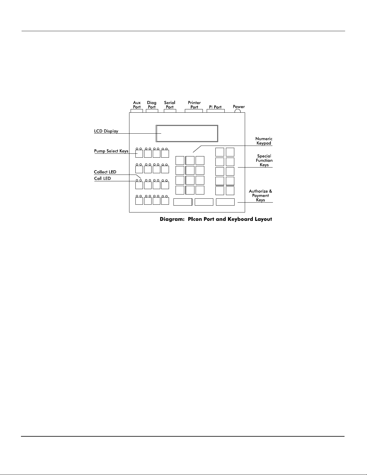
The basic PIcon system consists of several components — the console interconnect box and
cables. Refer to Diagram: PIcon Port and Keyboard Layout, which shows the various
connections of the PIcon system, including the port for optional printer.
To install the PIcon:
1. Place the console at the checkout counter of the station.
2. If using the PI DBox, refer to the PI DBox Installation Guide for detailed installation
instructions. Attach the PIcon system to the dispenser data distribution equipment for the
appropriate dispenser type.
3. If a printer is to be used with the PIcon, attach the printer cable to the 36-pin connector on
the back of the printer and the other end to the 15-pin serial port connector on the back of
the consoles.
4. If using the PI Configurator and the dispenser manufacturer’s DBox, refer to the PI
Configurator Installation Guide and the dispenser manufacturer’s DBox installation guide
for detailed instructions. Mount under the counter or on a wall adjacent to the console,
not more than five feet away. Using the PIcon cable, connect the configurator to the
PIcon, connection to the PIcon’s PIport.
5. Upon completion, apply power to all the components of the PIcon system and commence
programming, as outlined in the Program and Report section of this manual.
Rev 2.0 June 2006
Page 5
Page 10

PIcon Installation and Operation
Installation Warnings
Warning: Installation must comply with the National Electrical Code, as well as Federal, State,
Local and all applicable codes.
Warning: High voltages are present in this equipment. Disconnect all power before installing
to prevent personal injury or equipment damage.
Warning: Do not install PIcon units in a volatile, combustible or explosive atmosphere. All
PIcon units must be protected from severe vibration, extreme temperatures and excessive
humidity.
Any peripheral equipment is to be installed over a non-hazardous location.
Any peripheral equipment connected to the PIcon must be UL listed and using standard
connection communication.
The PIcon must be plugged into a dedicated 115 VAC wall socket with bonded earth ground.
Rev 2.0 June 2006
Page 6
Page 11

PIcon Installation and Operation
QUICK STARTUP
Basic Startup Procedure
This quick startup procedure lists the order and minimal programming steps for operation of the
PIcon. For more detailed explanations or for programming of optional modes, refer to the
following sections of this manual.
1. Program Mode 51 — Select port and dispenser type
2. Program Mode 1 — Dispenser setup information
3. Program Mode 2 — Product information
Rev 2.0 June 2006
Page 7
Page 12
PIcon Installation and Operation
OPERATION
Introduction
In this section, all functions available to the cashier for operation of the PIcon are outlined.
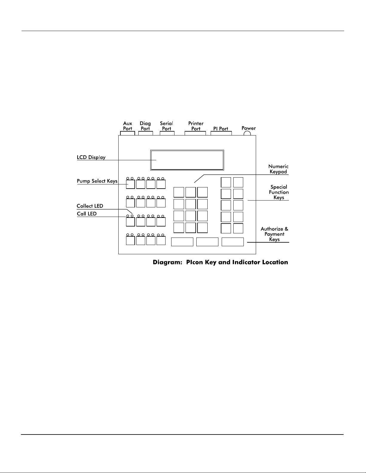
Table: Key Functions on the following page provides brief descriptions of key functions. Also,
refer to Diagram: PIcon Key and Indicator Location below for general locations of various
keys, indicators and display.
There are two types of operations for the cashier:
• Dispenser control — Initiated by pressing the appropriate pump select key, followed by
the keys corresponding to the command for the PIcon to make upon that dispenser.
• Select functions — Provide the cashier access to the shift, time and date, operator shift
report, shift change, and console deactivation functions.
Rev 2.0 June 2006
Page 8
Page 13

PIcon Installation and Operation
Active Keys
PUMP KEYS Select dispenser number
AUTHORIZE
CASH PAID Pay out the sale in cash
CREDIT PAID Pay out the sale in credit
VOLUME Display the volume of the sale
PPU Display the price per unit of sale
A/B Toggle between the A & B sales
PUMP STOP
PRINT Print a receipt
CHANGE
Authorize selected dispenser
Resume stopped dispenser
Stop an authorized dispenser
Stop all dispensers (hold 5 seconds)
Show the change of a prepay sale
Press twice to show the prepay amount
Clear incomplete prepay
MANAGER Enter/exit program & report modes
SELECT Refer to Operation Section, Special Functions
Table: Key Functions
Rev 2.0 June 2006
Page 9
Page 14

PIcon Installation and Operation
Display and Status Indicators
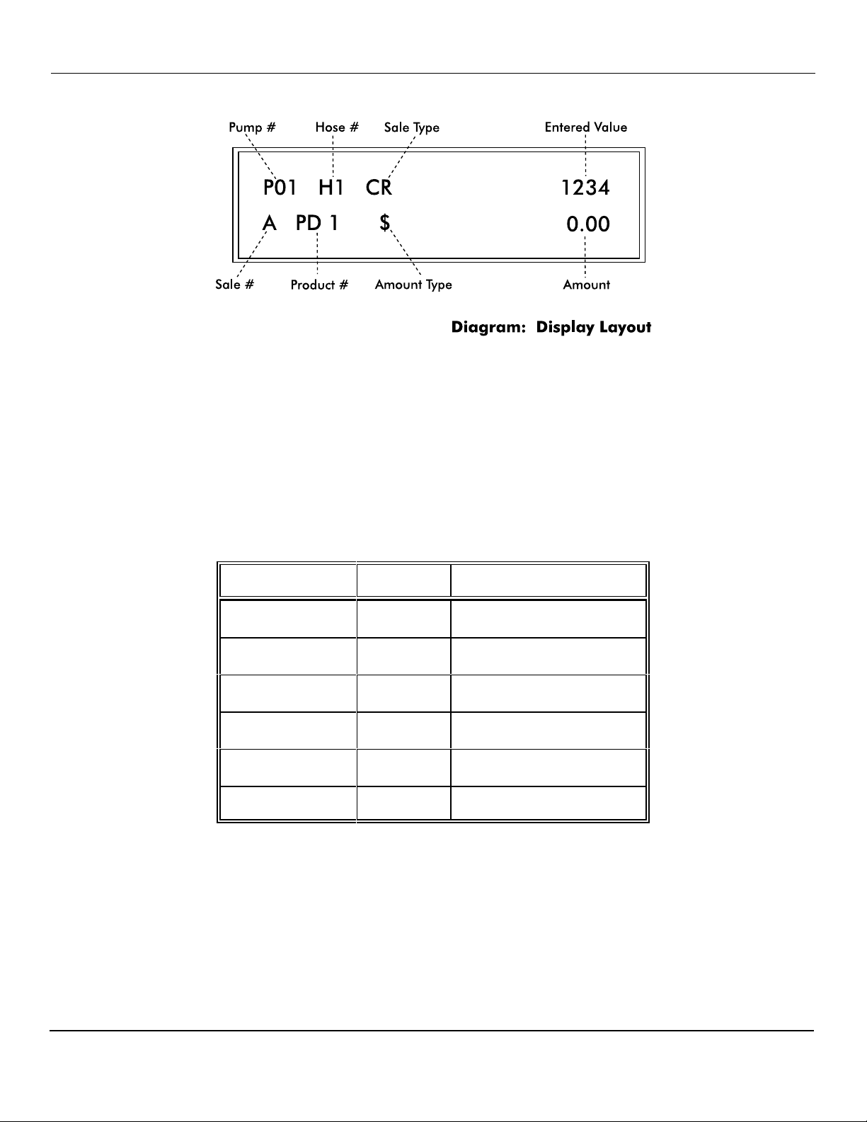
The LCD display provides the cashier with all sale information for the dispenser selected. It also
provides data such as time/date and shift totals reports when using the select functions. Listed
below in Table: Display Data are the various fields of data which may appear in the display
area, along with a brief description of each field.
Display Description
Indicates the current/active dispenser #/fueling position.
Pump #
Hose # Indicates the active hose at a fueling position.
Further key entry, such as authorization or payment will
apply to the current dispenser #.
Sale Type
Sale #
Product # Indicates the product type for the displayed sale.
Amount
Type
Amount Indicates the value, dollar or volume of the active sale.
Entered
Value
Indicates the method of payment selected for a sale —
cash (CA) or credit (CR).
Indicates which sale is selected — A or B (current sale or
previous sale respectively).
Indicates type of data being displayed in the amount field.
($) Sale amount, (V) Volume, (CG) Change amount, (LM)
Prepay Limit, (CA) Cash, (CR) Credit
Displays any data entered on the numeric keypad.
Table: Display Data
Rev 2.0 June 2006
Page 10
Page 15
PIcon Installation and Operation
The LEDs above each of the pump select keys are the status indicators for that particular
dispenser/fueling position. The green LED on the left indicates call/in use. The red LED on the
right indicates collect/stopped. Table: LED Indicators, below, shows the various states these
LEDs represent for each dispenser/fueling position.
GREEN LED RED LED STATUS
Fast Flash — Call for service
On Solid — Authorized
— Slow Flash Collect "A" Sale
— On Solid Dispenser Stopped
Fast Flash and Fast Flash Drive-Away
Slow Flash and Slow Flash Collect "A" and "B" Sales
Table: LED Indicators for Dispenser/Fueling Positions
Rev 2.0 June 2006
Page 11
Page 16

PIcon Installation and Operation
Sales
Authorization must be made for a sale as either a Postpay, Preset Postpay, or Prepay sale.
Table: Sales Procedure, below, describes the sequence for completing each type of authorized
sale.
NOTE: An actual key action is indicated by <____>
Sale
Type
Postpay
Preset
Postpay
Prepay
Procedure
To authorize a dispenser for a Postpay/Fillup operation,
press the appropriate <PUMP #> key and then press the
red <AUTHORIZE> key. To pay out the sale on the
console, press the <PUMP #> key. Press either <CASH
PAID> or <CREDIT PAID> key. To print a receipt, press
<PRINT>.
To authorize a dispenser for a preset amount, press the
appropriate <PUMP #> key and then enter the preset
amount on the numeric keypad. Press the red
<AUTHO RIZE> key. To pay out the sale on the console,
press the <PUMP #> key. Press either <CASH PAID> or
<CREDIT PAID> key. To print a receipt, press < PRINT> .
(Note that the amount entered on the numeric keypad
appears on the display in the ENTERED VALUE field.)
To authorize a dispenser for a prepay sale, press the
appropriate < PUMP # > key; then enter the amount paid
on the numeric keypad. (Note that the amount entered on
the numeric keypad appears on the display in the ENTERED
VALUE field.) Press method of payment, <CASH PAID> or
<CREDIT PAID> key; then the red <AUTHORIZE> key.
Table: Sales Procedure by Authorization Type
Rev 2.0 June 2006
Page 12
Page 17

PIcon Installation and Operation
PIcon has the capability of displaying stacked sales (A/B), with A representing the current sale
and B representing the previous sale. The B (previous) sale may either be already paid out or
waiting to be paid out.
If the transaction is a stacked sale (A/B), it is important to select the correct sale with the <A/B>
key before the method of payment — <CASH PAID> or <CREDIT PAID> key — is pressed.
The status indicators show the state of a transaction, such as call for service, collect, etc. (Refer
to the Quick Reference Guide for general sales procedures.)
Should it become necessary to stop all of the dispensers due to an emergency condition, press the
red <PUMP STOP> button and hold for five seconds. This will place all of the dispensers in a
stopped condition until the operator clears the emergency. This is accomplished by selecting
each dispenser with the <PUMP #> key and then pressing the <AUTHORIZE> key.
Rev 2.0 June 2006
Page 13
Page 18

PIcon Installation and Operation
Special Select Functions
Listed below are the five special operator select functions, along with the key sequences required
to execute them. Each key sequence begins with the operator pressing the <SELECT> key.
(Note that the display will prompt you to enter a function key for the appropriate mode.)
Select Function Key Sequence
Time/Date
Turn Console Off
View Current Shift
Totals by Product
Print Current Shift
Report
Change Shift
Press <SELECT> again
Press <CLEAR> to exit
Press <PUMP STOP>
Enter PIN Code
Press <ENTER> to turn back on
Press <ENTER>
Press <VOL> to see total volume
Press <CASH PAID> for cash total
Press <CREDIT PAID> for credit total
Press <ENTER> for next product
Press <PRINT>
Press <CHNG > (only after viewing the totals
or after report printing is completed)
Note: The Change Shift function may be
utilized only after the totals have been viewed
or printed and may be accessed only once
every hour.
Table: Select Key Functions
Select functions are accomplished by first pressing the <SELECT> key. The word Function
appears in the display, prompting the operator to enter the key for the desired function.
Rev 2.0 June 2006
Page 14
Page 19
PIcon Installation and Operation
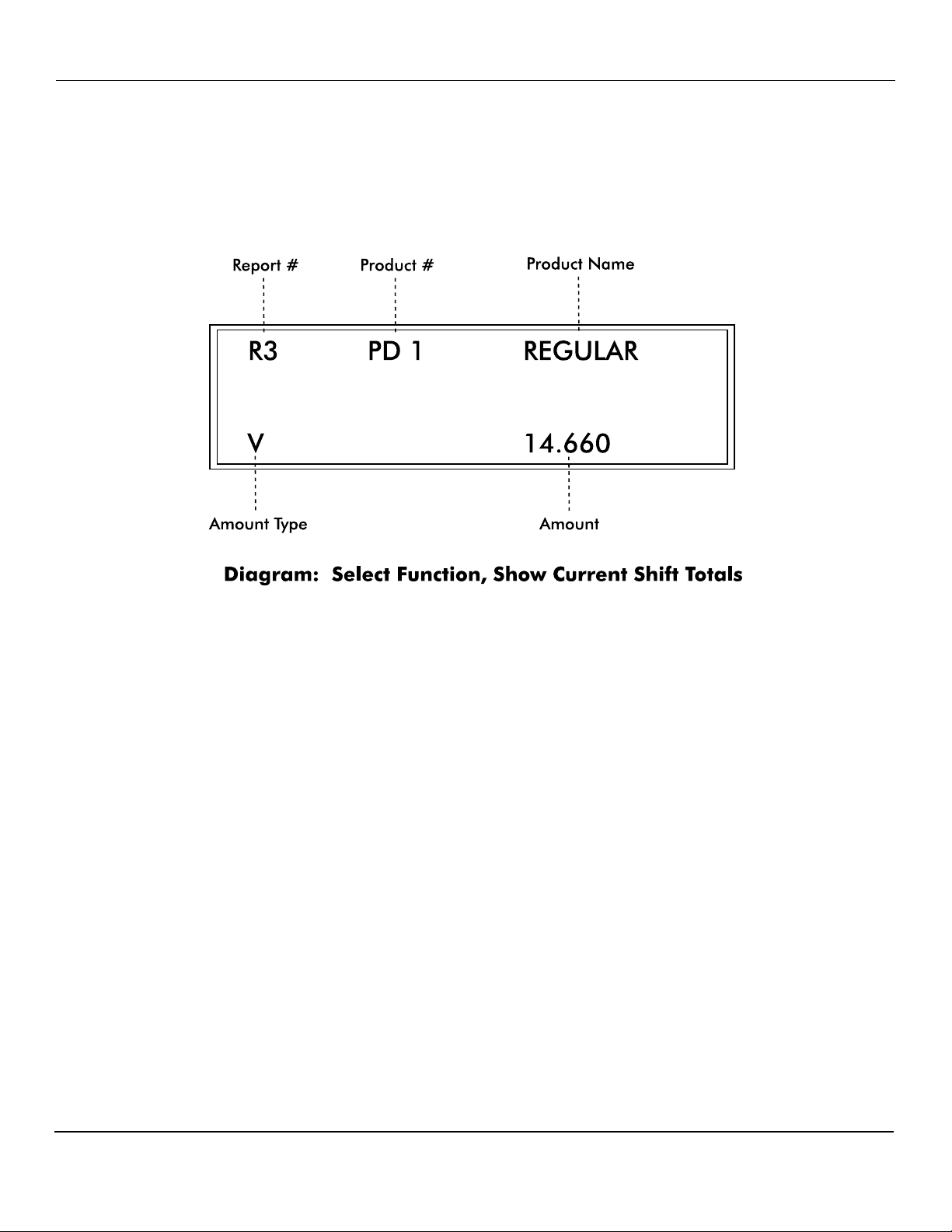
Show Current Shift Totals — When prompted for Function pressing the <ENTER> key
will begin to show current shift totals by first displaying the current volume shift totals for
product 1.
To view current cash shift totals, press the <CASH PAID> key. Current credit shift totals
may be viewed by pressing the <CREDIT PAID> key. Press <VOL> to view current
volume totals again.
To display current shift totals for additional product(s), continue to press the <ENTER> key.
After exhibiting the current shift totals for the selected product, the display will return to the
select function entry screen. If another select function is desired, it may be entered, or the
select function mode may be exited by pressing the <MNGR> key.
Print Current Shift Totals — At the Function prompt, press the <PRINT> key to print the
current shift report.
After printing the current shift report, the display will return to the select function entry
screen. If another select function is desired, it may be entered, or the select function mode
may be exited by pressing the <CLEAR> key.
Rev 2.0 June 2006
Page 15
Page 20

PIcon Installation and Operation
Perform Shift Change — To execute a shift change, simply press the <CHNG> key at the
Function prompt. When this has been accomplished, the PIcon changes the current shift total
to zero. The last shift total is then stored as shift 1. At any time, there are four stored shift
reports. They are the current shift, shift 1, shift 2, and shift 3, with shift 3 being the oldest.
Please note that all shift reports are time/date stamped and contain a unique two-digit number
that increments by one each time a shift change takes place.
Note: As a precautionary measure, the Shift Change function may only be implemented if the
following conditions have been met:
• Current shift totals must have been viewed or printed in their entirety, using the Special
Select Functions <ENTER> or <PRINT>.
• At least one hour must have elapsed since the last shift change.
After performing shift change, the display will return to the select function entry screen. If
another select function is desired, it may be entered, or the select function mode may be
exited by pressing the <CLEAR> key.
Show Console Clock — The PIcon’s built-in clock/calendar provides accurate time/date
stamping on reports and sales receipts. After being prompted for Function, press
<SELECT> to read the time and date.
Time and date will be displayed until another key is pressed. If another select function is
desired, it may be entered, or the select function mode may be exited by pressing the
<MNGR> key.
Turn Off Console — At the Function prompt, press <PUMP STOP>. At this point, all
LEDs are turned off and the word Off flashes on the display. Note that any fueling
transactions that have already begun when the PIcon was turned off will be allowed to run to
completion.
To turn the PIcon back on, enter the Operator or Manager PIN Code on the numeric pad and
press the <ENTER> key. The default Operator PIN Code is set at the factory to 1111. The
default Manager PIN Code is 2422. PIN Codes do not appear in the display as they are
entered on the numeric keypad. (See the Program & Report Section of this manual for
instructions on changing the PIN Codes.)
Rev 2.0 June 2006
Page 16
Page 21

PIcon Program & Report
PROGRAM & REPORT
Introduction
The Program & Report Section describes the operation and resulting information provided by the
PIcon program and report functions. These functions allow the manager to configure the PIcon
for the specific type of operation desired and to retrieve important data collected. This
management information is protected by the use of a unique Manager PIN Code (factory default
— 2422). This Manager PIN Code may be changed by the manager at any time through the use
of one of the program and report functions. Manager Modes 10 and 11 may be accessed through
operator’s PIN code (default 1111).
As you review this section of the manual, please refer to Diagram: PIcon Key and Indicator
Location, located in previous Operator Introduction section, for general locations of the various
keys, indicators and display. While using program and report functions, the fields on the display
will vary from function to function, depending upon the type of data being displayed or
requested.
Refer to Program & Report in the Quick Reference Guide.
Rev 2.0 June 2006
Page 17
Page 22

PIcon Program & Report
PIN Code Access
To access PIcon program and report features, a sequence utilizing a valid PIN Code must first be
entered. Access is divided into two categories — manager and operator. The manager, using a
Manager PIN Code, has access to all program and report functions. Report functions (Modes 10
and 11) are also available to the operator, who uses an Operator PIN Code. Manager and
operator access are described below.
Manager Access
Entry of the correct Manager PIN Code allows access to all program and report functions.
First, press <MNGR> key. The display will prompt you to enter your PIN Code. Enter this
PIN Code on the numeric keypad. (This number, with a maximum of four digits, is stored in
the PIcon. Its purpose is to limit access to PIcon program and report data. The number 2422
is the factory default value for the Manager PIN Code.) Next, press the <ENTER> key. M 0
will appear in the display, prompting you to enter the desired function mode number on the
numeric keypad. (See mode descriptions.) Press <ENTER> again to generate the requested
program & report function sequence. At this point, if you wish to return to the operator
mode, press the <MNGR> key to exit from manager modes.
Operator Access
Access to report functions is accomplished through the entry of a valid Operator PIN Code.
First, press the <MNGR> key. You will be prompted by the display to enter your PIN Code.
Enter your Operator PIN Code on the numeric keypad. (This number, with a maximum of
four digits, is stored in the PIcon. Its purpose is to limit access to PIcon report data. The
number 1111 is the factory default value for the Operator PIN Code.) Next, press the
<ENTER> key. M 0 will appear in the display, prompting you to enter the desired function
mode number on the numeric keypad. Press <ENTER> again to generate the requested
program & report function sequence. Press the <MNGR> key to exit current mode.
Rev 2.0 June 2006
Page 18
Page 23
PIcon Program & Report
Mode Descriptions
The sequence for manager access must be completed before programming features can be
utilized through the various program modes. The sequence for either manager access or operator
access allows generation of reports (Modes 10 and 11). Each set of instructions for the following
program and report modes assumes that the appropriate manager/operator access has already
been executed and that the mode number (M 0) prompt now appears in the display. To operate
the PIcon, Modes 1 and 2 (at least) must be programmed.
Mode 1 — Dispenser Setup Information (Manager only)
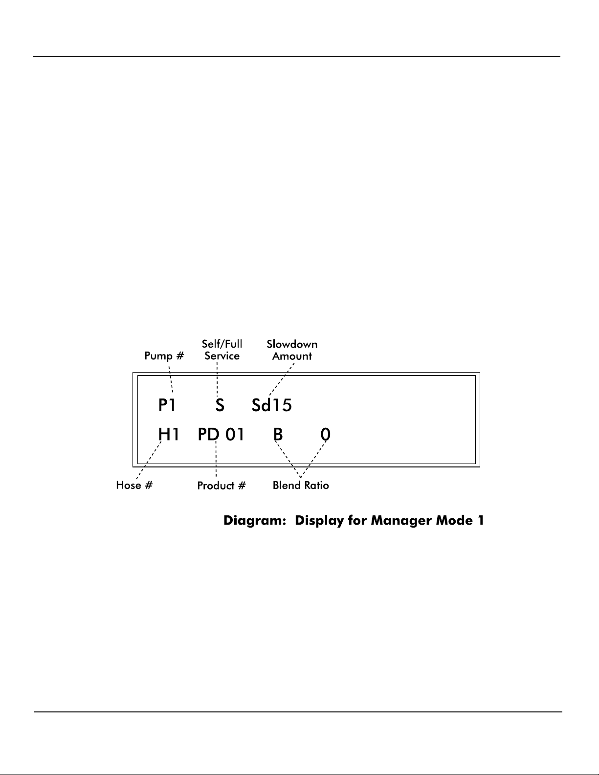
In Mode 1, hose selection, product, service, blend and slowdown amount are entered for each
dispenser/fueling position controlled by the PIcon. After being prompted for mode number
(M 0), press <1> on the numeric keypad and then press <ENTER>. You are now in Mode 1.
To initiate dispenser programming, press the <PUMP #__> key for the first dispenser/fueling
position at the site (usually Dispenser #1).
Rev 2.0 June 2006
Page 19
Page 24

PIcon Program & Report
Hose Selection — After the dispenser number is chosen, Hose 1 is indicated on the
display. From this point, the following parameters may be set for Hose 1. If
programming a multi-product dispenser, parameters must be set for all hoses.
• Product — Press the <GRADE> key to scroll to the desired product for the current
hose displayed. During this step, pressing the <AUTHORIZE> key will clear the
product number for reentry.
• Service — To select service type, press the <CHNG> key to toggle between full-
or self-service for the specified dispenser. Setting service type on one hose selects
it for the entire dispenser.
• Blend — If the dispenser is a blending dispenser, on the numeric keypad enter the
amount, in percent of hose 1, to be dispensed by the selected hose. Press
<ENTER>. (Default is set at 0.) Remember that any data entered on the numeric
keypad will appear on the display.
• Slowdown Amount — To set slowdown amount, enter new value on the numeric
keypad. Press <PUMP STOP>. Setting slowdown amount on one hose sets it for
the entire dispenser. Default is 15 cents. Maximum is 99 cents.
If the dispenser is a multi-product dispenser, press <SELECT> to scroll to the next hose to
be programmed. Follow this procedure to program each hose of each dispenser at the site.
To exit Mode 1, press the <MNGR> key. The PIcon display returns to M 0, the mode entry
prompt. To exit programming mode completely, press the <MNGR> key again. The PIcon
will return to operator mode.
Rev 2.0 June 2006
Page 20
Page 25
PIcon Program & Report
Mode 2 — Product Information (Manager only)
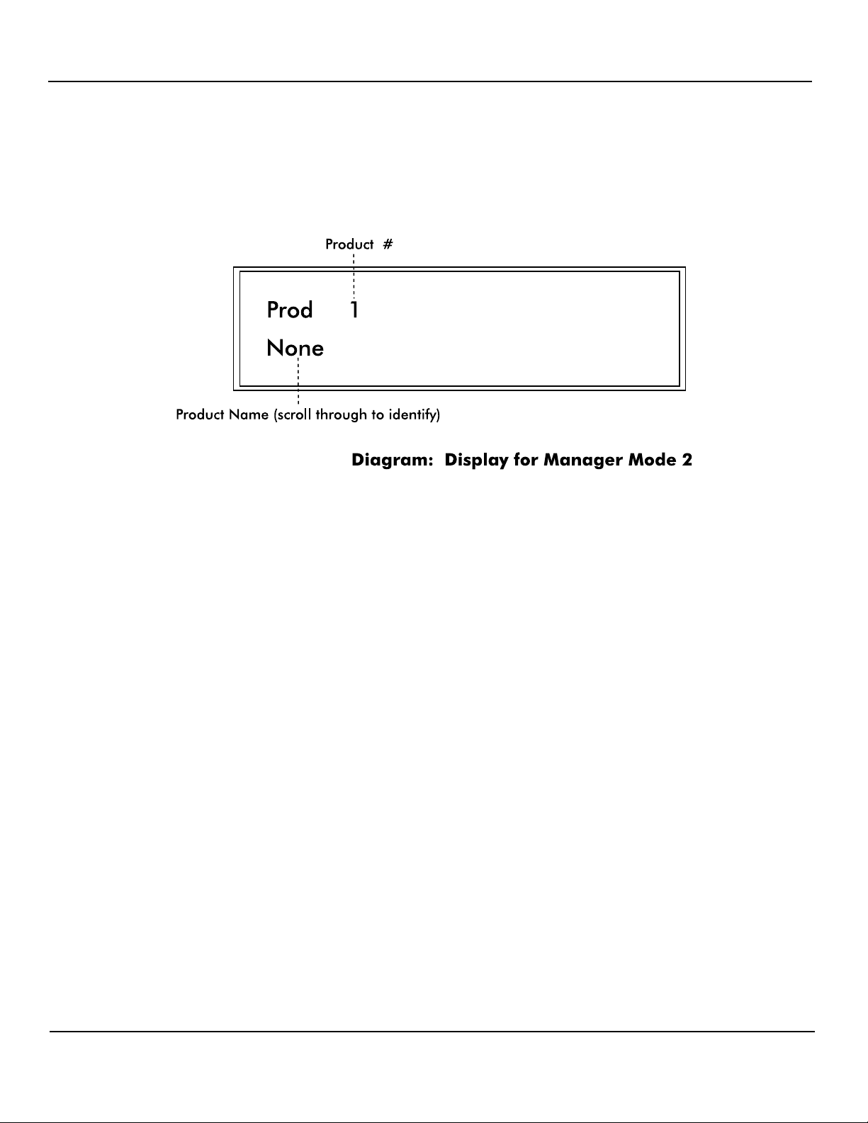
In this mode, Product Name, Cash PPU and Credit PPU for each product at the site are
programmed. To enter this mode from the M 0, mode number prompt, press <2> on the
numeric keypad and then press <ENTER>. You are now in Mode 2.
Product Name — The display now prompts for information about product #1. To assign
a product name such as UL REG or DIESEL to this product, press the <GRADE> key
until the desired product name is presented in the display. If you wish to just view the
product name already assigned, press the <SELECT> key and the name will appear in
the display.
Cash PPU — To set the Cash PPU for a product, enter the desired PPU on the numeric
keypad and press the <CASH PAID> key. The three decimal places are assumed.
Credit PPU — To set the Credit PPU for a product, enter the desired PPU on the
numeric keypad and press the <CREDIT PAID> key. The three decimal places are
assumed.
As the Cash and Credit PPUs are entered, numeric key errors may be erased by pressing
the <CLEAR> key and reentering the data. Also, Cash and Credit PPUs may be viewed
by pressing the <CASH PAID> or <CREDIT PAID> key. The value will appear in the
display. Note: Both cash and credit prices must be programmed for each product —
even if prices are the same.
To proceed to the next product number to be programmed, press the <ENTER> key. Follow
this procedure for each product type at the site.
Rev 2.0 June 2006
Page 21
Page 26
PIcon Program & Report
Exit Mode 2 by pressing the <MNGR> key. The PIcon display returns to M 0, the mode
entry prompt. To exit programming mode completely and return to operator mode, press the
<MNGR> key again.
Mode 3 — Beeper Settings (Manager only)
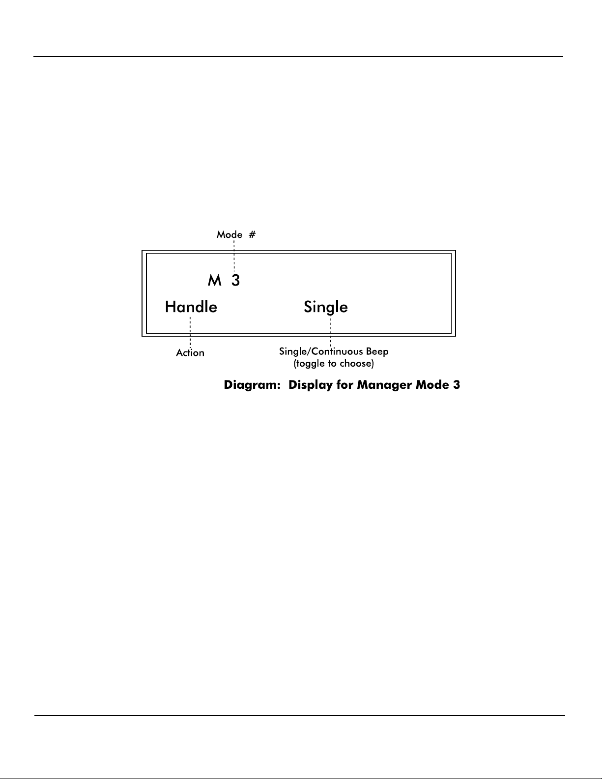
Mode 3 is used to program single or continuous beeps for Handle, Collect and Drive-Away.
(Note: The console defaults to a single beep unless set otherwise.) To enter Mode 3 from M
0, the mode number prompt, enter <3> on the numeric keypad and press <ENTER>.
Handle/Call for Service — The display first will prompt for selection of the style of
beep associated with a Handle/Call for Service. To change the style of beep, press the
<SELECT> key and toggle between single and continuous. To proceed to the next
option setting, press <ENTER>.
Collect — The display now prompts for selection of the style of beep associated with a
Collect condition. To change the style of beep, press the <SELECT> key and toggle
between single and continuous. To proceed to the next option setting, press the
<ENTER> key.
Drive-Away — The display now prompts for selection of the style of beep associated
with a Drive-Away condition. To change the style of beep, press the <SELECT> key
and toggle between single and continuous.
Exit Mode 3 by pressing the <MNGR> key. M 0, the mode entry prompt, will appear on the
display. To exit programming mode completely and return to operator mode, press the
<MNGR> key again.
Rev 2.0 June 2006
Page 22
Page 27
PIcon Program & Report
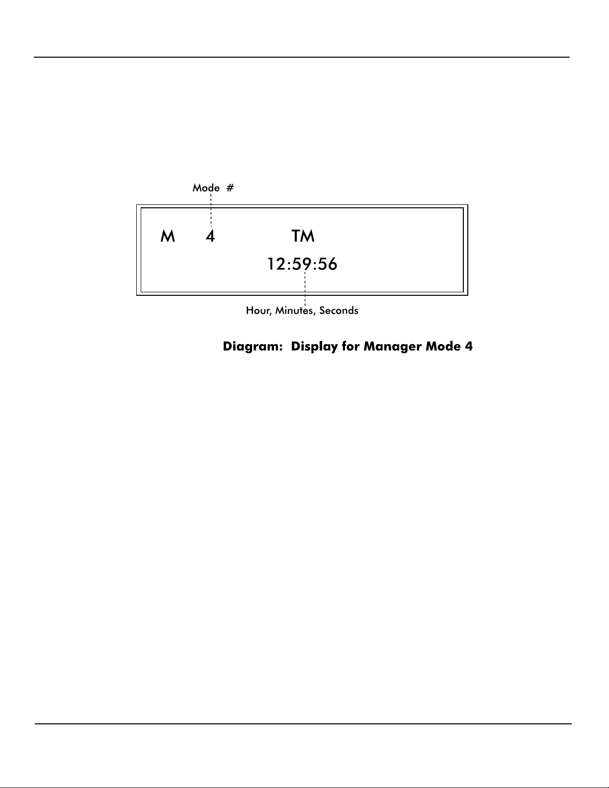
Mode 4 — Clock/Calendar (Manager only)
Mode 4 allows the setting of time, date and year. To enter mode 4 from the M 0, mode
number prompt, press <4> and press <ENTER>. The PIcon is now in programming Mode
4.
Time — Time already set in the PIcon will be displayed. To change the time, enter the
new time on the numeric keypad in 24 hour format. The new time will appear in the
display as it is entered. Seconds are not entered and will be automatically set as 00.
Press <ENTER> and the time will be updated in the PIcon. Press <ENTER> again to
proceed to program the date.
Date — Date already set in PIcon will be displayed under DT. You may change the date
by entering the new date on the numeric keypad in mmdd format. The new date will
appear in the display as it is entered. Press <ENTER> and the date will be updated in the
PIcon. Press <ENTER> again to proceed to program the year.
Year — Year already set in PIcon will be displayed under YR. Date may be changed by
entering the new year on the numeric keypad in four digits. The new year will display as
it is being entered. Press <ENTER> and the year will be updated.
To exit Mode 4, press the <MNGR> key or the <ENTER> key. M 0, the mode entry
prompt, will appear on the display. To exit programming mode completely and return to
operator mode, press the <MNGR> key again.
Rev 2.0 June 2006
Page 23
Page 28
PIcon Program & Report
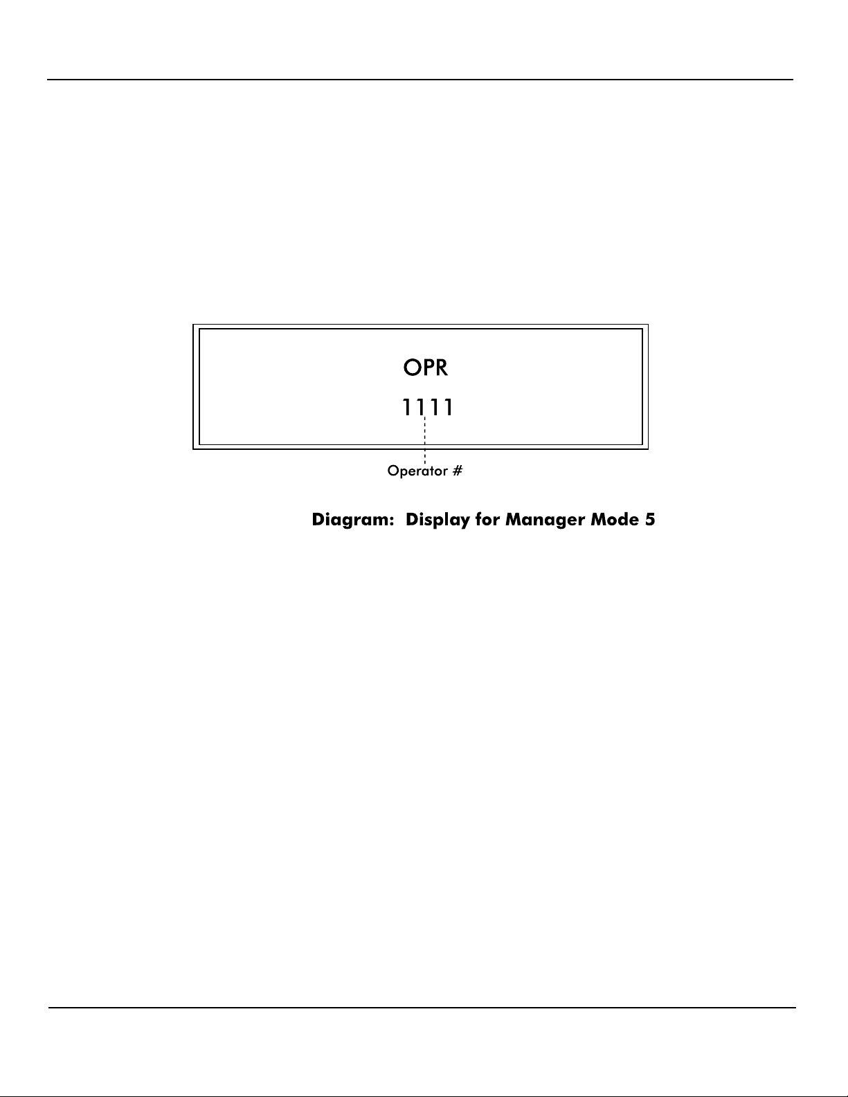
Mode 5 —Program Operator/Manger PIN Codes
(Manager only)
WARNING: Care should be observed when using this mode. If the PIN Code is altered, be
sure to make note of the new PIN Code and save in a safe location.
Mode 5 allows the setting of Operator PIN Codes and Manager PIN Codes. To enter this
mode from the M 0, mode number prompt, press <5> and press <ENTER>. The PIcon is
now in programming Mode 5.
Operator PIN Codes — The display will show the existing Operator PIN Code under
OPR. (The default Operator PIN Code is 1111.) To change the code, enter the new
number (up to 4 digits) on the numeric keypad and press <ENTER>. The new Operator
PIN code will appear on the display. To proceed to program Manager PIN Codes, press
<ENTER> again.
Manager PIN Codes — Under MGR, the display will show the existing Manager PIN
Code. (The default Manager PIN Code is 2422.) To change the code, enter the new
number (up to 4 digits) on the numeric keypad and press <ENTER>. The new Manager
PIN Code will appear on the display. Pressing <ENTER> again will take you back to
Operator PIN Codes.
To exit Mode 5, press <MNGR>.
Modes 6 - 9 are reserved.
Rev 2.0 June 2006
Page 24
Page 29
PIcon Program & Report
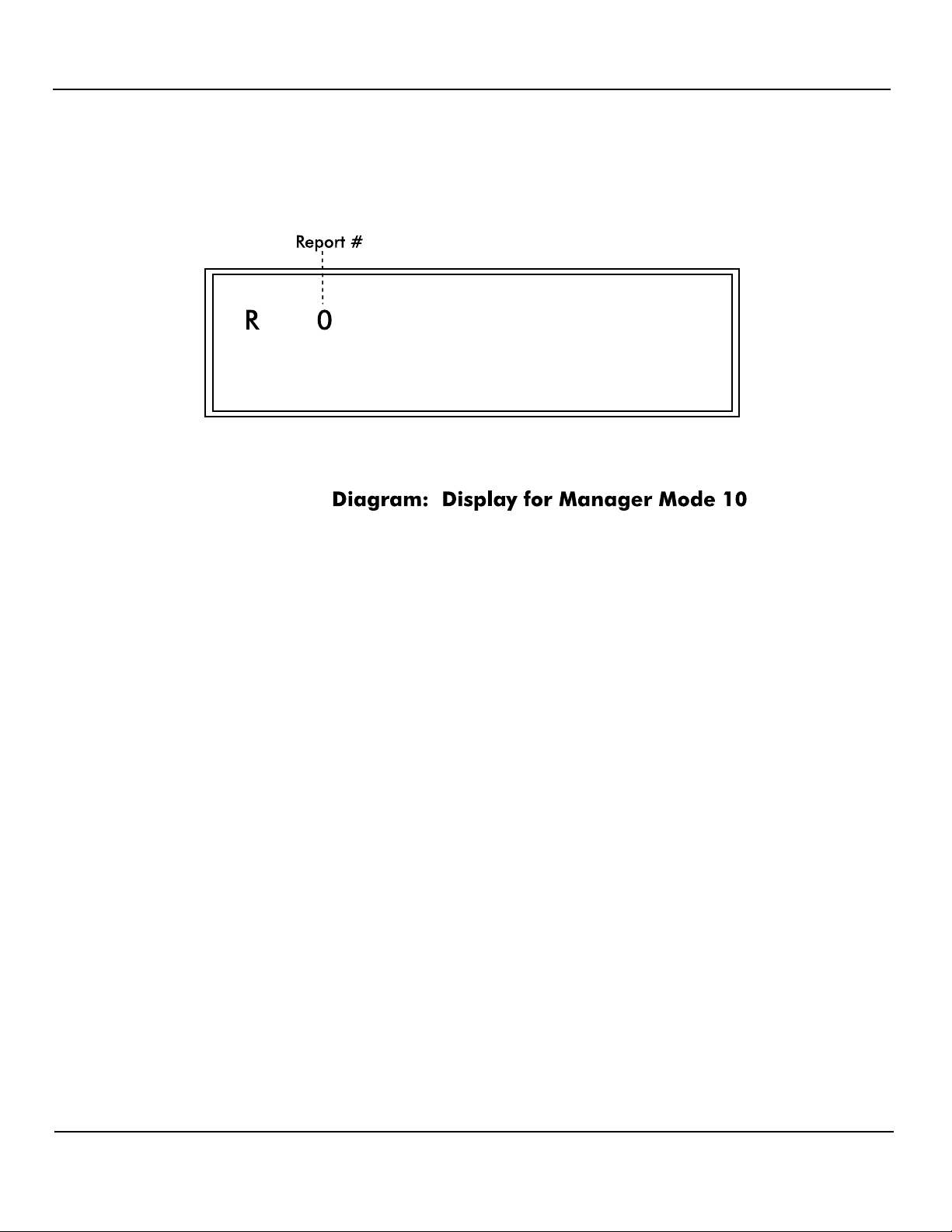
Mode 10 — Read Reports (Manager/Operator)
In Mode 10, totals reports may be generated and displayed. To enter this mode from the M 0,
mode number prompt, enter <10> on the keypad and press <ENTER>.
The display will show an R 0, prompting you to enter a report type code. From the following
reports, select the one you would like displayed.
1 Resettable Totals
2 Non-Resettable Totals
3 Shift 0 Totals (current shift)
4 Shift 1 Totals
5 Shift 2 Totals
6 Shift 3 Totals
7 Polled Dispenser Totals
Select the report number and enter it on the PIcon keypad; then press <ENTER>. The
beginning data for the report is shown in the display. Use the following keys to scroll
through the report.
<ENTER> Display next product totals
<VOL> Display the volume total
<CASH PAID> Display the cash total
<CREDIT PAID> Display the credit total
<MNGR> Exit Mode 10
Rev 2.0 June 2006
Page 25
Page 30
PIcon Program & Report
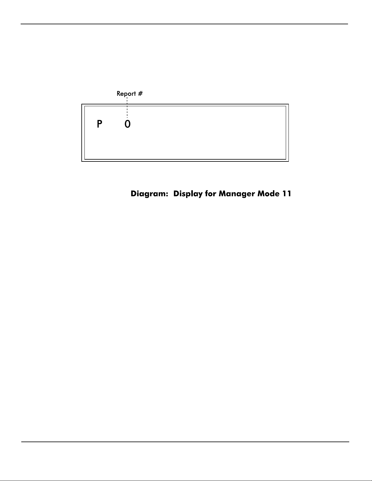
Mode 11 — Print Reports/Program Print Header (Manager/Operator)
Mode 11 enables reports to be generated and printed on the printer attached to the PIcon, as
well as programming the print header. To enter this mode from the M 0, mode number
prompt, enter <11> on the numeric keypad and press <ENTER>.
P 0 will be displayed, prompting you to enter a report type code. Use the following table to
select which type of report you would like printed by the PIcon.
(If no printer is connected, display will read NOT ON LINE.)
1 Resettable Totals
2 Non-Resettable Totals
3 Shift 0 Totals (current shift)
4 Shift 1 Totals
5 Shift 2 Totals
6 Shift 3 Totals
7 Polled Dispenser Totals
8 Console Program Information
9 Print Header — Under Print Header, the print header for the printer receipt is created and
edited.
For printing reports 1-8, select report number, <1> through <8>, and enter it on the PIcon
keypad. Then press <ENTER>. Data for the report will be printed. To print additional
reports, select another report option.
Rev 2.0 June 2006
Page 26
Page 31

PIcon Program & Report
Initiate programming of Print Header by pressing <9> and then <ENTER>. The display
shows the beginning information for the printer header. If your header has not been
programmed or has been cleared, the cursor will prompt you for your first character entry.
(Refer to Table: Print Header Character Codes, at the end of Mode 11 description, for
a numeric code which represents the characters available for your use on the printer
header.) Determine the character you wish to place in the first position of the header and
look up the numeric code. Enter this numeric code on the keypad and press <ENTER>.
The character will appear on the display, and has been saved in memory. For each
subsequent character, follow the sequence described above.
There are two special numeric codes for the header: <10> indicates a new line in the
header; <01> is the code for end of header. Enter the new line code at the point where
the printer should cease printing on the current line and go to the beginning of the next
line. The end of header code is entered after the entire header is entered and will tell the
PIcon that no more characters are needed in the header.
Special editing features are available for use under Print Header:
<ENTER> without entering a numeric code — The display cursor will increment to
the next character in the header.
<SELECT> without entering a numeric code — The display cursor will go back one
character in the header.
<CHNG> without entering a numeric code — The entire printer header will be
cleared.
<PRINT> without entering a numeric code — The printer will print the header that is
programmed.
<MNGR> — Exit Print Header programming.
Press <MNGR> to exit Mode 11.
Rev 2.0 June 2006
Page 27
Page 32

PIcon Program & Report
Print Header Character Codes
01 = end of header 10 = new line
0 48 F 70 U 85 j 106 y 121 - 45 < 96
1 49 G 71 V 86 k 107 z 122 . 46 { 123
118
119
spac
32 / 47 | 124
e
42
*
+
43
]
^
93
94
2 50 H 72 W 87 l 108
3 51 I 73 X 88 m 109 ! 33 : 58 } 125
4 52 J 74 Y 89 n 110 " 34 ; 59 ~ 126
5 53 K 75 Z 90 o 111 # 35 < 60
6 54 L 76 a 97 p 112 $ 36 = 61
7 55 M 77 b 98 q 113 % 37 > 62
8 56 N 78 c 99 r 114 & 38 ? 63
9 57 O 79 d 100 s 115 ' 39 @ 64
A 65 P 80 e 101 t 116 ( 40 [ 91
B 66 Q 81 f 102 u 117 ) 41 \ 92
67
C
68
D
82
R
83
S
103
g
h
104
v
w
69
E
84
T
105
i
120
x
44
,
95
_
Table: Print Header Character Codes
Rev 2.0 June 2006
Page 28
Page 33
PIcon Program & Report
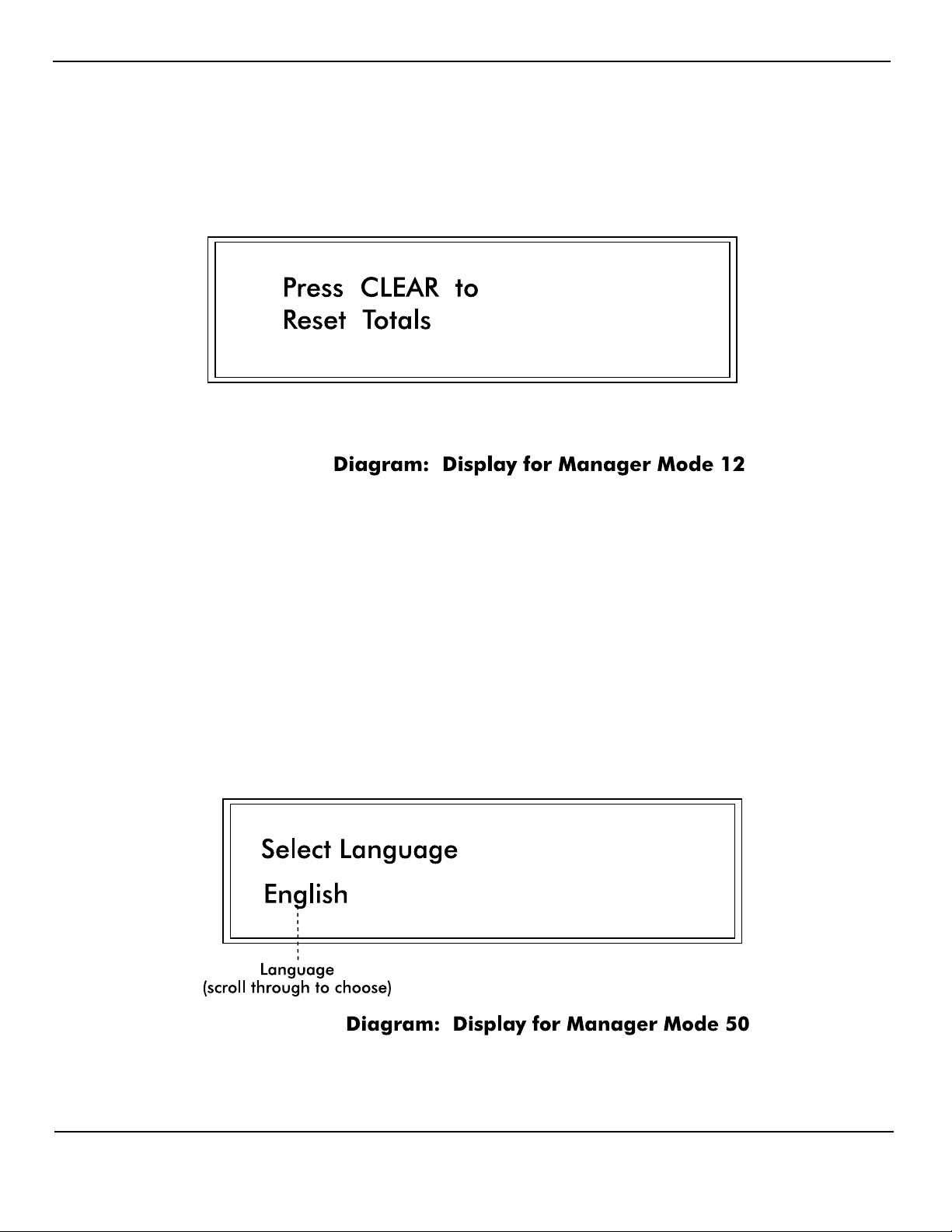
Mode 12 — Clear Resettable Totals (Manager only)
Mode 12 is used to reset resettable totals by clearing them to zero. To enter this mode from
the M 0, mode number prompt, enter <12> on the keypad and press <ENTER>.
The display will show Press Clear. If you wish to zero all resettable totals, proceed by
pressing <CLEAR>.
Press any key to exit Mode 12.
Mode 50 — Select Language (Manager only)
To enter this mode from the M 0, mode number prompt, enter <50> on the keypad and press
<ENTER>. Press <SELECT> to scroll through the languages available. Language selection
pertains to printed reports and some display prompts.
Press <MNGR> to exit Mode 50.
Rev 2.0 June 2006
Page 29
Page 34
PIcon Program & Report
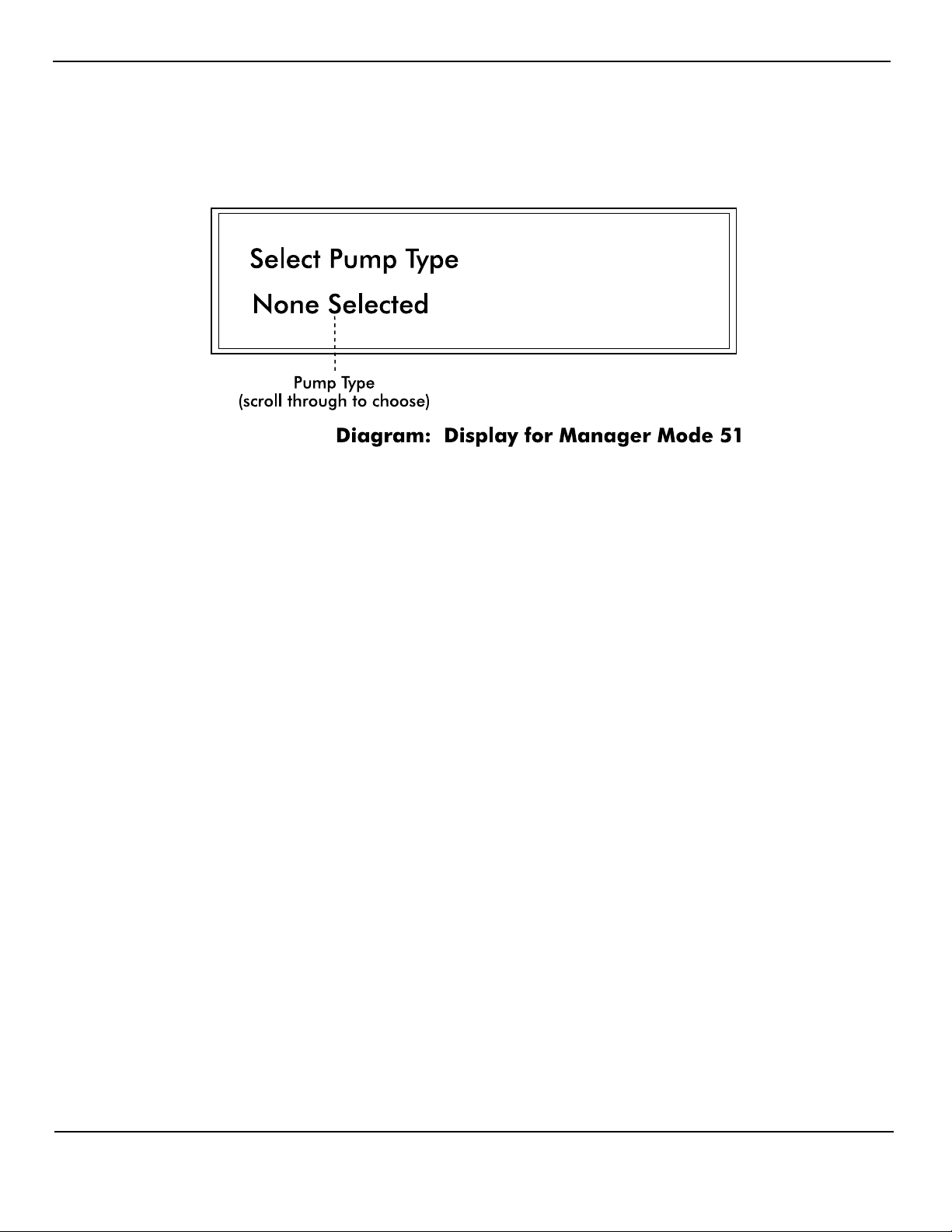
Mode 51 — Select Dispenser Type (Manager only)
To enter this mode from the M 0, mode number prompt, enter <51> on the keypad and press
<ENTER>. The default, indicated on the screen, is None Selected for dispenser type.
Select Pump — To select the dispenser brand, press <SELECT> to scroll through the
brands, stopping when your dispenser’s brand name appears.
Press <MNGR> to exit this mode. You will be prompted for the option of clearing memory
back to factory defaults. Press <CLEAR> to clear all totals or <MNGR> to decline this
option and exit the mode. The PIcon will reset.
Mode 60 — Pump Configuration (Manager only)
Pump specific, advanced configuration. To enter Pump Configuration mode from the M0,
mode number prompt, enter <60> on the keypad and press <ENTER>. Press <0>, <1>, etc.
on the numeric keypad to select the configurable item and then press <A/B> to toggle
between the options for the selected item.
Contact your dealer for assistance.
Mode 70 — ATG Activation (Manager only)
To enter Automatic Tank Gauging mode from the M 0, mode number prompt, enter <70> on
the keypad and press <ENTER>. Press <A/B> to toggle between Enable and Disable
selection. This mode available only on PIcons configured with AUX Port.
Rev 2.0 June 2006
Page 30
Page 35
PIcon Diagnostics
DIAGNOSTICS
PIcon Internal Diagnostics
Refer to our web site, www.pie-corp.com, or call PIE at 919 266-4442
for more comprehensive diagnostics.
The PIcon has on-board diagnostics which are helpful in solving problems encountered in the
field. Below are a few of the standard diagnostic functions:
• Show Dispenser Information
• Display Version Numbers
• Monitor a Port
• Download Print Header
• Download Program Update
To access diagnostics, a computer running a terminal emulation software such as Procomm or
Hyperterm for Windows is required. The diagnostic port is a serial port with the following
connection parameters. Note: A standard 9 pin serial cable is used to connect the terminal device
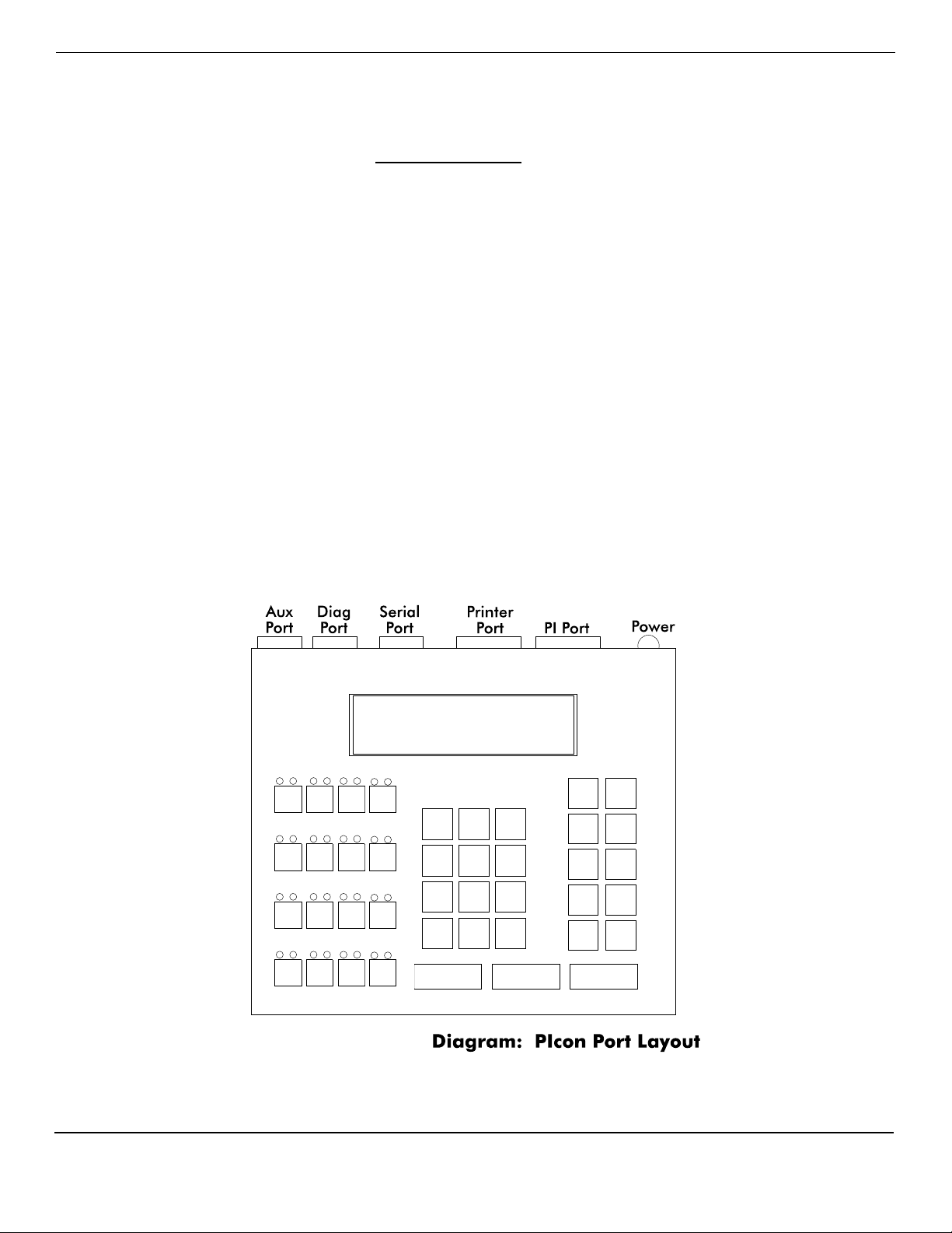
to the diagnostic port, not a null modem cable. See Diagram: PIcon Port Layout for connector
locations.
Rev 2.0 June 2006
Page 31
Page 36

PIcon Diagnostics
• Baud Rate 57,600
• Data Bits 8
• Parity No
• Stop Bits 1
• Flow Control None
After connecting to the diagnostics port, starting the terminal emulation program, power up the
PIcon and type a question mark (?). A menu will appear, displaying the various diagnostic
functions available. To select a function, type the letter shown in the menu. Some features will
prompt for additional information. To exit a diagnostic function, press the escape key. The
display will show a diagnostic prompt, waiting for another command from the user. Any time a
prompt is shown, a question mark may be entered to display the menu.
Two important diagnostic commands are Download Print Header and Download Program
Update.
Download Print Header
The purpose of this command is to load a print header from a computer into the PIcon. First, the
print header should be written in Notepad, using plain text — with no special formatting or tabs.
(The appearance of centering, tabs, etc., must be accomplished through the use of additional hard
spaces.) Then, print header may be downloaded by following this procedure:
• From DIAG> enter ? to view menu.
• Select D, Section Diagnostics.
• Under Support, select C, Printer Section.
• From PRN> enter ? to view menu.
• Select D, Download the Print Header.
• At the prompt, download may be aborted by pressing ESC or continued by entering any
other key.
• If continuing download, C’s will continue to appear onscreen until the file to be
downloaded is selected. To select the print header file, go to Hyperterm’s toolbar and
select Transfer, then Send File. At the dialog box, browse for file to be downloaded.
Select the file you have previously written for the print header. Under the Protocol
section of the dialog box, select Xmodem. Press Send button. File will be downloaded,
notification will appear when it is complete, and PRN> will appear. Press ESC until
DIAG> appears.
Rev 2.0 June 2006
Page 32
Page 37

PIcon Diagnostics
Download Application
Upgrade files from Progressive International are loaded using the Download Application
function, following these steps:
• At DIAG> press ? to view menu.
• Select S, Security Code.
• An Access Code appears. This numeric value is subtracted from 100. The two digits
which result should be reversed and entered at the Enter Security Code>. (For example if
Access Code is 79, subtract 79 from 100 for a result of 21. Reverse these two digits and
enter 12 when prompted at the Enter Security Code>.) Press enter.
• At Diag(P)> press ? to view menu.
• Press X, Download Application.
• Notification will appear — Start Download Application. C’s will continue to display
onscreen until the file to be downloaded is selected. To select the file to download, go to
Hyperterm’s toolbar and select Transfer, then Send File. At the dialog box, browse for
file to be downloaded. Select the upgrade file. Under the Protocol section of the dialog
box, select Xmodem. Press Send button. File will be downloaded. Once complete,
PIcon will reset itself and DIAG> will appear.
Normally, PIcon settings which have been programmed will remain unchanged when upgrades
are downloaded. As a precaution, PIE recommends that a printout of Mode 11 Report 8
(Console Program Information) be made before upgrading since major revisions could possibly
reset all programming.
Rev 2.0 June 2006
Page 33
 Loading...