

Page 1

PCXZ
Fuel Control Systems
Installation Guide
Page 2

1106 Great Falls Court, Suite G
Knightdale, NC 27545
Phone 919 266-4442 • Fax 919 266-4588
www.pie-corp.com
© Copyright 2005
Progressive International Electronics
Page 3

PCXZ Fuel Control Systems
Installation Guide
CONTENTS
System Installation ......................................................... 1
System Installation Warnings ...............................................1
System Evaluation.......................................................2
System Installation Checklist ............................................... 2
System Installation Requirements ............................................ 3
Description of PCXZ Equipment ............................................. 3
PCXZ Installation .......................................................4
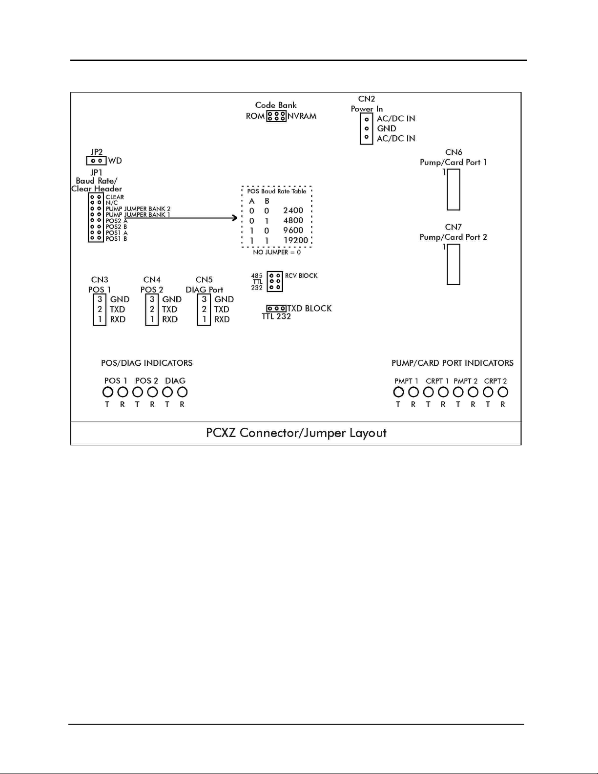
Diagram: PCXZ Connector/Jumper Layout . . . . . . . . . . . . . . . . . . . . . . . . . . . . . . . 5
Dispenser & Reader Specific Installation ....................................... 6
Gilbarco Electronic Dispenser ........................................... 6
Listing: Gilbarco DBoxes............................................6
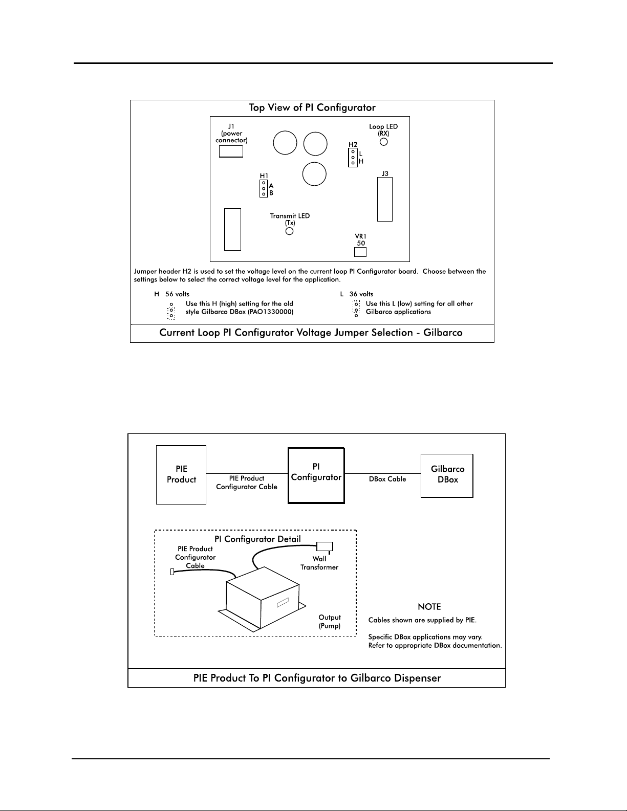
Diagram: Current Loop Configurator Voltage Jumper Selection . . . . . . . . . . . . . . . . 7
Diagram: PCXZ to Gilbarco Electronic Dispenser . . . . . . . . . . . . . . . . . . . . . . . . . . . 7
Gilbarco CRIND.....................................................8
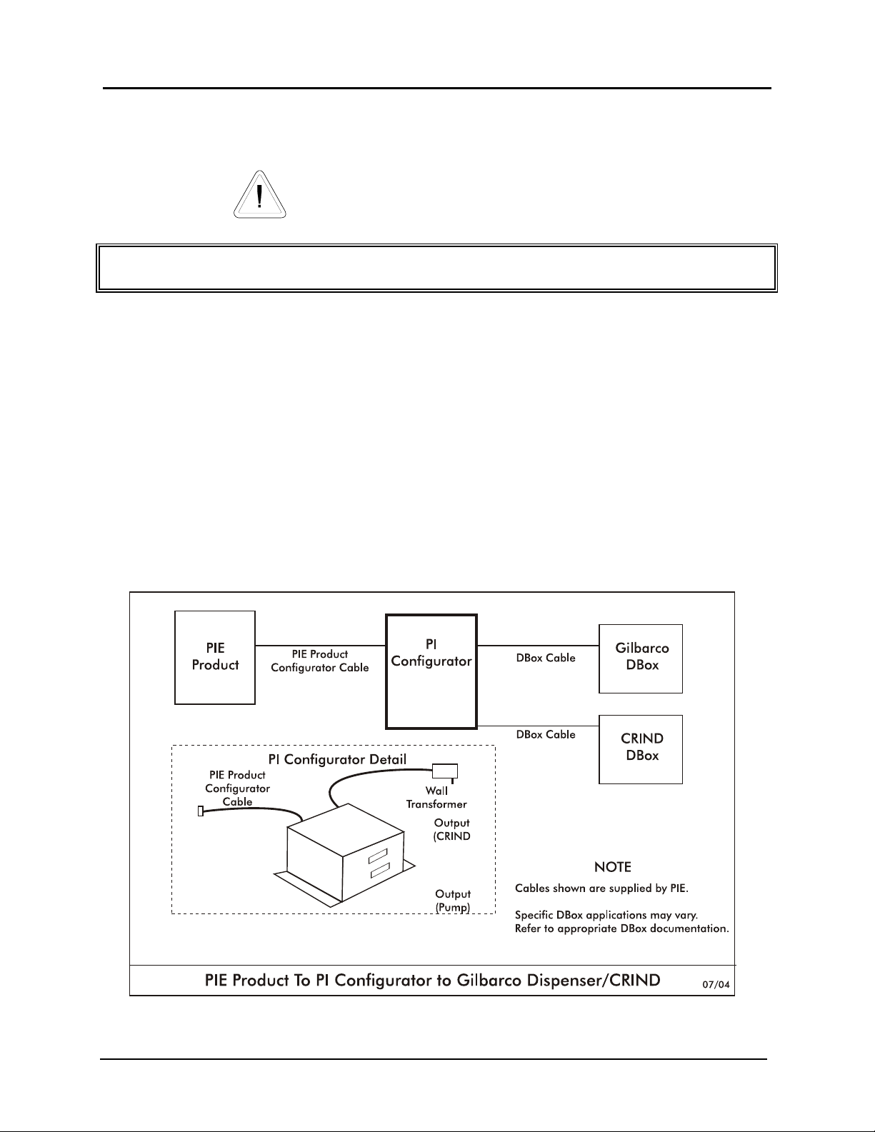
Diagram: PCXZ to Gilbarco Electronic Dispenser/CRIND . . . . . . . . . . . . . . . . . . . . . 8
Wayne/Dresser Electronic Dispenser .......................................9
Diagram: PCXZ to Wayne/Dresser Electronic Dispenser . . . . . . . . . . . . . . . . . . . . . . 9
Diagram: Wayne/Dresser DBox Connection Guide . . . . . . . . . . . . . . . . . . . . . . . . 10
Wayne/Dresser CAT .................................................11
Diagram: PCXZ to Wayne/Dresser Electronic Dispenser/CAT . . . . . . . . . . . . . . . . . 11
Diagram: PIE’s DBox for Wayne/Dresser CAT . . . . . . . . . . . . . . . . . . . . . . . . . . . . 12
Tokheim Electronic Dispenser........................................... 13
Diagram: PCXZ to Tokheim 67 DBox .................................. 15
Diagram: PCXZ to Tokheim 98/94 Power Center . . . . . . . . . . . . . . . . . . . . . . . . . 15
Diagram: Tokheim Configurator Board Emergency Relay Jumper . . . . . . . . . . . . . . 16
Tokheim DPT ...................................................... 17
Diagram: PCXZ to Tokheim Dispenser/DPT . . . . . . . . . . . . . . . . . . . . . . . . . . . . . . 17
Schlumberger Electronic Dispenser ....................................... 18
Diagram: PCXZ to Schlumberger Electronic Dispenser . . . . . . . . . . . . . . . . . . . . . . 18
Schlumberger Electronic Dispenser Option 98 Programming Example . . . . . . . . . . . 19
Schlumberger CardScan ..............................................24
Diagram: PCXZ to Schlumberger Electronic Dispenser/CardScan . . . . . . . . . . . . . . 24
Kraus Electronic Dispenser.............................................25
Diagram: PCXZ to Kraus Electronic Dispensers . . . . . . . . . . . . . . . . . . . . . . . . . . . 26
Diagram: Kraus Configurator Board...................................26
Diagram: Kraus Dispenser Head Layout . . . . . . . . . . . . . . . . . . . . . . . . . . . . . . . . 27
Bennett Electronic Dispenser ...........................................28
Diagram: PCXZ to Bennett Electronic Dispensers . . . . . . . . . . . . . . . . . . . . . . . . . . 28
Diagram: Bennett Connector Layout................................... 29
iii
Page 4

Tatsuno Electronic Dispenser ...........................................30
Diagram: PIE RS485 DBox Connections ................................30
Diagram: PCXZ to Tatsuno Electronic Dispensers . . . . . . . . . . . . . . . . . . . . . . . . . . 31
Nuovo Pignone Electronic Dispenser...................................... 32
Diagram: PIE RS485 DBox Connections ................................32
Diagram: PCXZ to Nuovo Pignone Electronic Dispensers . . . . . . . . . . . . . . . . . . . . 33
Diagnostics ............................................................. 34
PCXZ Internal Diagnostics ................................................ 34
Diagram: PCXZ Diagnostic Port Location . . . . . . . . . . . . . . . . . . . . . . . . . . . . . . . . 34
Dispenser Control Center Demo Test Program . . . . . . . . . . . . . . . . . . . . . . . . . . . . . . . . . 35
Command Structure for Downloading
PCXZ Downloadable Controllers ........................................38
PCXZ General Diagnostics ...............................................40
General Testing Procedures ........................................... 40
Preparation for Tech Support Calls ....................................... 42
Gilbarco .........................................................43
W a y n e / D r e s s e r..................................................... 44
Tokheim .........................................................45
Schlumberger ......................................................46
Kraus ........................................................... 47
Bennett .......................................................... 47
iv
Page 5

PCXZ
HISTORY OF DOCUMENTATION
CHANGES & REVISIONS
Version 1.0 — June 1997
Version 1.1 — October 1997 (preliminary release)
Version 2.0 — January 1999
Version 3.0 — November 1999
Version 4.0 — July 2001
Version 4.1 — February 2004
Added Kraus software levels
Deleted Gasboy
Added Tatsuno
Added Nuovo Pignone
Version 4.2 — April 2005
Added missing document
PURPOSE OF THIS DOCUMENT
This manual contains instructions for installation of the PCXZ Fuel Control System to electronic fuel
dispenser computers and to peripheral equipment such as the point of sale terminal (POS).
Instructions for installing or servicing electronic fuel dispensers and POS terminals are not included.
For more detail on any product not manufactured by PIE, or for PIE’s own distribution box, always
refer to that product’s accompanying documentation.
NOTICE
Progressive International Electronics reserves the right to revise and improve this document as
required. This publication details our Fuel Control Systems at this time, and may not accurately
describe these products at all times in the future. Specifications are subject to change without notice.
PATENTS
Progressive International Products are manufactured or sold under one or more of the following U.S.
patents.
5,790,410
5,831,861
5,694,326
5,663,887
5,557,529
5,394,336
5,361,216
5,270,943
5,108,742
COPYRIGHT
Copyright © 2004 Progressive International Electronics, Inc. All rights reserved. No part of this
publication may be reproduced, stored in a retrieval system or transmitted, in any form or by any
means, electronic, mechanical, photocopying, recording, or otherwise, without the prior written
permission of Progressive International Electronics, Inc.
All brands or product names are trademarks or registered trademarks of their respective companies.
v
Page 6

PCXZ
WARRANTY
Progressive International Electronics, Inc. (PIE) warrants to the Purchaser of the PCC fuel control
equipment manufactured by PIE against defects in material or workmanship for 1 (one) year from
date of shipment. Seller will replace or repair defective parts or issue credits to the Purchaser’s
account in accordance with the following Conditions of Warranty.
Conditions of Warranty
C Credit will be applied only when defective parts are received and inspected. An Return
Merchandise Authorization (RMA) number must be obtained before returning defective goods
to PIE.
C Decisions to repair or replace defective equipment are solely at the discretion of PIE.
C When parts shipments are made prior to receiving required warranty request and defective
parts, they will be billed to the Purchaser.
C In all cases, approved warranty requests will be expedited by issuing the appropriate credit to
the Purchaser’s account or shipping replacement parts.
C Credits will not be issued for parts and no cash refunds for warranty credits will be made.
C All components and parts must be returned to the factory prepaid and, in turn, replacement
components and parts will be returned prepaid by the factory.
C PIE’s warranty applies only if the equipment has been installed and used in accordance with
PIE’s instructions. Warranty is void if any unauthorized alteration or addition has been made
to the equipment or if it has been subject to damage caused by abuse, act of nature,
misapplication, accident or improper operation.
C PIE’s liability for any damages, including contribution and indemnification, arising out of or in
any way connected with the supplying of the equipment or its use, shall not in any case
exceed the cost of repair of the equipment as herein provided. Upon expiration of the
warranty, all such liability, as well as any other liability, shall terminate.
C Nothing contained herein shall make the Purchaser, its agents or employees, an agent or
representative of PIE, and PIE assumes no responsibility of any act, omission, representation
or warranty by the Purchaser or anyone else except as expressly stated herein.
C The final decision as to the validity of any claims arising under the warranty shall be
determined solely by PIE.
The foregoing warranty is in lieu of all other warranties, expressed or implied, including, but not
limited to, the implied warranties of merchantability and fitness for a particular purpose which
exceed the aforesaid obligations and are hereby disclaimed and excluded by Progressive
International Electronics.
vi
Page 7

PCXZ
EXPLANATION OF DOCUMENT STANDARDS
The following documentation standards are applied throughout this document.
I Comments are noted in italics.
X Variable data formats are represented by X(s).
Electrical hazards and other warnings are indicated with this caution sign.
These abbreviations are used.
DBox Distribution box — either dispenser manufacturer’s or Progressive International
Electronics’
MPD Multiple product dispenser
PC Personal computer
PCXZ PIE’s Fuel Control System (referred to as PIE Product in diagrams)
PIE Progressive International Electronics, Inc.
POS Point of sale terminal
SPD Single product dispenser
vii
Page 8

NOTES PERTAINING TO INSTALLATION SITE
___________________________________________________________________________________
___________________________________________________________________________________
___________________________________________________________________________________
___________________________________________________________________________________
___________________________________________________________________________________
___________________________________________________________________________________
___________________________________________________________________________________
___________________________________________________________________________________
___________________________________________________________________________________
___________________________________________________________________________________
___________________________________________________________________________________
___________________________________________________________________________________
___________________________________________________________________________________
___________________________________________________________________________________
___________________________________________________________________________________
___________________________________________________________________________________
___________________________________________________________________________________
___________________________________________________________________________________
___________________________________________________________________________________
___________________________________________________________________________________
___________________________________________________________________________________
___________________________________________________________________________________
___________________________________________________________________________________
viii
Page 9

Progressive International Electronics PCXZ
System Installation
System Installation Warnings
Safety hazards are inherent with all electrical equipment. Standard precautions must be taken at all times during installation and
operation of the PCXZ systems. In addition to normal electrical precautions, the following points should be noted during installation.
C Installation must comply with National Electrical Code, as well as Federal, State/Provincial,
Local, and all applicable codes.
C High voltages are present in the PCXZ components, as well as the equipment to which it is
attaching. To prevent personal injury or equipment damage, disconnect all power before
proceeding with installation.
C PCXZ equipment must be installed in nonvolatile, noncombustible, nonexplosive areas. The
main box must be protected from severe vibration, extreme temperatures and excessive
humidity.
C All PCXZ peripheral equipment must be installed in nonhazardous locations and must be UL-
listed, using standard RS232 communication.
For Use in USA
Installation of the PCXZ fuel control system must comply with the requirements of the National
Electrical Code (NFPA 70), the Automotive and Marine Station Code (NFPA 30A), and all Federal,
State, Local, and applicable safety codes.
For Use in Canada
Installation of the PCXZ fuel control system must comply with the requirements of the Canadian
Electrical Code, the Flammable and Combustible Liquid Code, and all Federal, Provincial, State,
Local, and applicable safety codes.
The installation of the systems covered by this manual in conjunction with equipment not UL Listed has not been evaluated by the
Underwriters Laboratories and is outside the intended use of this equipment. Warning: All dispensing equipment discussed in this
manual is not UL Listed and the combination has not been evaluated by Underwriters Laboratories.
Version 4.2/April 2005 Page 1
PCXZinstall
Page 10

Progressive International Electronics PCXZ
System Installation
System Evaluation
IMPORTANT!
Before determining what PCXZ components are to be purchased, and prior to the installation of any
equipment, it is essential that the fuel dispensing system be thoroughly evaluated. A site survey
should be completed, listing all the fuel dispensing related equipment.
The survey should include:
C Model numbers of both dispenser and DBox
C Manufacturer of equipment
C Number of dispensers
C A simple drawing describing the station layout
After your site survey is complete, Progressive International’s sales staff and technicians will be available to assist you in determining
which product(s) are appropriate for a particular fuel dispensing application.
System Installation Checklist
The fuel dispensing system should be installed in the following order.
1. Install dispensers according to manufacturer’s specifications. See System Installation Requirements on
following page.
2. Test dispensers with same brand console. See System Installation Requirements on following page.
3. Mount PCXZ. Refer to PCXZ Installation section of this manual.
4. Connect system components to specific dispenser box (DBox). If DBox is supplied by dispenser
manufacturer, see Dispenser & Reader Specific Installation section of this manual. If DBox is supplied by PIE, see PIE DBox
Installation Guide.
5. Test with PCC Demo Test Program. Refer to Diagnostics section of this manual.
6. Install POS application and test fully integrated system.
To ensure smooth system integration, it is recommended that the petroleum equipment service technician for the account be available to
resolve dispenser-related issues.
Version 4.2/April 2005 Page 2
PCXZinstall
Page 11

Progressive International Electronics PCXZ
System Installation
System Installation Requirements
In preparation for the PCXZ installation, ensure that the following requirements have been met.
1. Following the manufacturer’s installation instructions, install the dispensing equipment (pumps
and data distribution boxes).
2. Test all dispensers in stand-alone (manual) mode.
3. Test all dispensers with same brand console to check basic dispenser functionality and
confirm a working communications link between the DBox and the dispensers. On dispensers
which have programmable identification numbers, ensure that the numbers are set correctly.
If multiple dispensers contain the same i.d. number, communication conflicts will occur.
All dispensers and communications should be functioning properly before proceeding with PCXZ
installation. If not, refer questions to the dispenser vendor/manufacturer.
Description of PCXZ Equipment
PCXZ systems are made up of the components listed below. Using this checklist, identify and
familiarize yourself with each of the components in your shipment. For further clarification, refer to the block
diagrams at the end of each dispenser section in the Dispenser & Reader Specific Installation portion of this manual.
PCXZ Equipment Checklist
U PCXZ Main Box — with connectors for POS, diagnostics and configurator box
U Configurator Box(es) — as many as 2 boxes which adapt the PCXZ to the appropriate brand(s) of fuel dispenser; wall
transformer attached
U Dispenser Connection Cable — standard 3-foot cable which connects the configurator box to the fuel dispenser
distribution box
U Config Cable — cable which connects the PCXZ board to the configurator box
U Installation Manual
U System/Test Diskette
Version 4.2/April 2005 Page 3
PCXZinstall
Page 12

Progressive International Electronics PCXZ
System Installation
PCXZ Installation
Read entire installation manual before attempting to install the system. Note warnings on previous page.
1. A junction box must be provided which has only enough receptacle outlets to accommodate
the transformers of the PCXZ system. See PCXZ Power Requirements listed below.
PCXZ Power Requirements
The PCXZ and the configurator box must be powered from a dedicated 115 VAC single circuit breaker, with no
other devices connected to wire or breaker. Do not use a switched neutral breaker. The neutral must come
directly from the neutral bus in the electric supply panel. No other neutral circuits may be connected to this
wire.
The electric supply system earth bond must connect to a driven ground rod or other earth bonding systems that
comply with the National Electrical Code, Article 250.
Failure to comply with these requirements will void warranty.
2. Securely mount PCXZ main box in a nonhazardous location.
Mount the configurator box(es) within two feet of the main box and attach the PCXZ config
cable (supplied by PIE) between the two boxes. Refer to Dispenser & Reader Specific Installation section of this
manual for instructions on connecting the PIE configurator box to the dispenser data distribution box.
Connect the RS232 serial cable between the Comm port of the POS and the POS port on the
PCXZ main box. If necessary, jumpers may be reconfigured. Refer to Diagram: PCXZ Connector/Jumper
Layout following instructions.
3. Plug in the wall transformers for the main box and the configurator box to the dedicated
outlets.
4. After power is applied, test installed equipment using PCC Demo Test Program supplied on
system diskette. Refer to PCC Demo Test Program in the Diagnostics section of this document.
5. If the dispensers have readers that are being controlled by the POS, test the readers at this
time by running the PCCR test program supplied on the system/test diskette. If the PCCR test
program performs correctly, the PCXZ has been installed properly.
6. Carefully following the vendor’s setup instructions, run the POS application. If the system fails at
this point, contact the vendor for additional instructions.
For the POS/PCXZ system to function properly, the POS must be programmed for the exact number of dispensers to be controlled by the
POS/PCXZ system. (An MPD has multiple hoses, but is considered to be only two dispensers — one dispenser on either side.)
Version 4.2/April 2005 Page 4
PCXZinstall
Page 13
Progressive International Electronics PCXZ
Diagram: PCXZ Connector/Jumper Layout
Version 4.2/April 2005 Page 5
PCXZinstall
Page 14
Progressive International Electronics PCXZ
System Installation
Dispenser & Reader Specific Installation
Gilbarco Electronic Dispenser
Note all warnings at the beginning of installation section.
Instructions for DBox installations in this manual are for the specific DBoxes supplied by dispenser manufacturers. If using DBoxes
supplied by Progressive International, refer to the Installation Guide which accompanies PIE’s DBox.
PIE ships current loop configurators as standard equipment. Some Gilbarco DBoxes are configured for RS422 operation. If the RS422
DBox cannot be converted to current loop operation, you must use an RS422 configurator and cables. Contact your PIE dealer to order.
Following instructions on preceding pages of installation section of this manual, mount PCXZ and
configurator box(es). Then, follow specific instructions for connecting PCXZ system to the appropriate
Gilbarco distribution box (DBox). Gilbarco DBoxes are listed on the following page.
1. Disconnect the Gilbarco console from the distribution box and connect the Gilbarco style
configurator box to the Gilbarco DBox using the appropriate cable supplied by PIE. Refer to
Diagram: PCXZ to Gilbarco Electronic Dispenser following this section.
2. Return to the PCXZ Installation Section for remaining system installation procedures.
Note: All Single Product Dispensers (SPDs) must be set for grade 1.
Listing: Gilbarco DBoxes
Gilbarco DBox Part # Description
PA01330000 Old Style with DIN connector
PA0261X000010 Universal Style with 1 board current loop
PA0261X000020 Universal Style with 2 boards current loop
PA0261X000011 Universal Style with 1 board RS422
PA0261X000021 Universal Style with 2 boards RS422
PA0306X010 Gsite Style with 1 board RJ45 connector
PA0306X020 Gsite style with 2 boards RJ45 connector
PA0242 TS1000 Style
Version 4.2/April 2005 Page 6
PCXZinstall
Page 15
Progressive International Electronics PCXZ
Diagram: Current Loop Configurator Voltage Jumper Selection
Diagram: PCXZ to Gilbarco Electronic Dispenser
Version 4.2/April 2005 Page 7
PCXZinstall
Page 16
Progressive International Electronics PCXZ
System Installation
Dispenser & Reader Specific Installation
Gilbarco CRIND
Note all warnings at the beginning of installation section.
Instructions for DBox installations in this manual are for the specific DBoxes supplied by dispenser manufacturers. If using DBoxes
supplied by Progressive International, refer to the Installation Guide which accompanies PIE’s DBox.
Following instructions on preceding pages of installation section of this manual, install PCXZ,
configurator box(es) and dispenser. After successfully testing the dispensers using the PCXZ system,
then follow these specific instructions for connecting the Gilbarco reader. See Diagram: PCXZ to Gilbarco
Dispenser/CRIND.
1. Locate the reader connector on the PIE dual Gilbarco configurator box. Plug the appropriate
cable supplied by PIE into this connector and plug the other end into the Gilbarco CRIND
distribution box or the PIE DBox. Refer to Diagram: PCXZ to Gilbarco Electronic Dispenser/CRIND which follows.
2. Return to the PCXZ Installation Section for remaining system installation procedures.
Diagram: PCXZ to Gilbarco Electronic Dispenser/CRIND
Version 4.2/April 2005 Page 8
PCXZinstall
Page 17
Progressive International Electronics PCXZ
System Installation
Dispenser & Reader Specific Installation
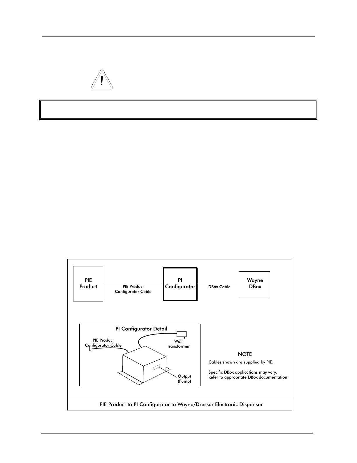
Wayne/Dresser Electronic Dispenser
Note all warnings at the beginning of installation section.
Instructions for DBox installations in this manual are for the specific DBoxes supplied by dispenser manufacturers. If using DBoxes
supplied by Progressive International, refer to the Installation Guide which accompanies PIE’s DBox.
Following instructions on preceding pages of installation section of this manual, install PCXZ and
configurator box(es). Then, follow specific instructions for connecting PCXZ system to the
Wayne/Dresser DBox. Refer to Diagram: PCXZ to Wayne/Dresser Dispenser.
1. Disconnect the Wayne/Dresser console from the distribution box and connect the
Wayne/Dresser style configurator box to the DBox using the appropriate cable supplied by
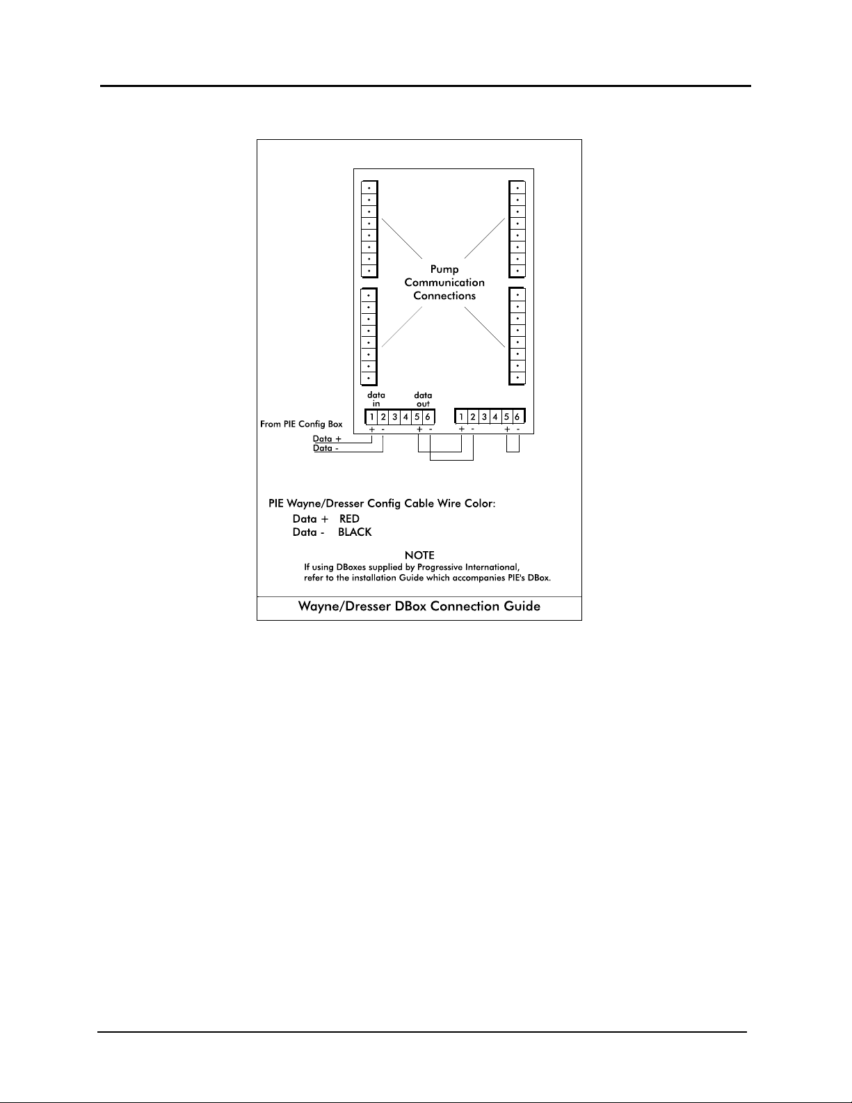
PIE. See Diagram: Wayne/Dresser DBox Connection Guide at end of this section.)
2. Return to the PCXZ Installation Section for remaining system installation procedures.
3. If configuring for liter units, ensure that pump jumpers DA and DB at position JP1 are
installed. See Diagram: PCXZ Connector/Jumper Layout.
Diagram: PCXZ to Wayne/Dresser Electronic Dispenser
Version 4.2/April 2005 Page 9
PCXZinstall
Page 18
Progressive International Electronics PCXZ
Diagram: Wayne/Dresser DBox Connection Guide
Version 4.2/April 2005 Page 10
PCXZinstall
Page 19
Progressive International Electronics PCXZ
System Installation
Dispenser & Reader Specific Installation
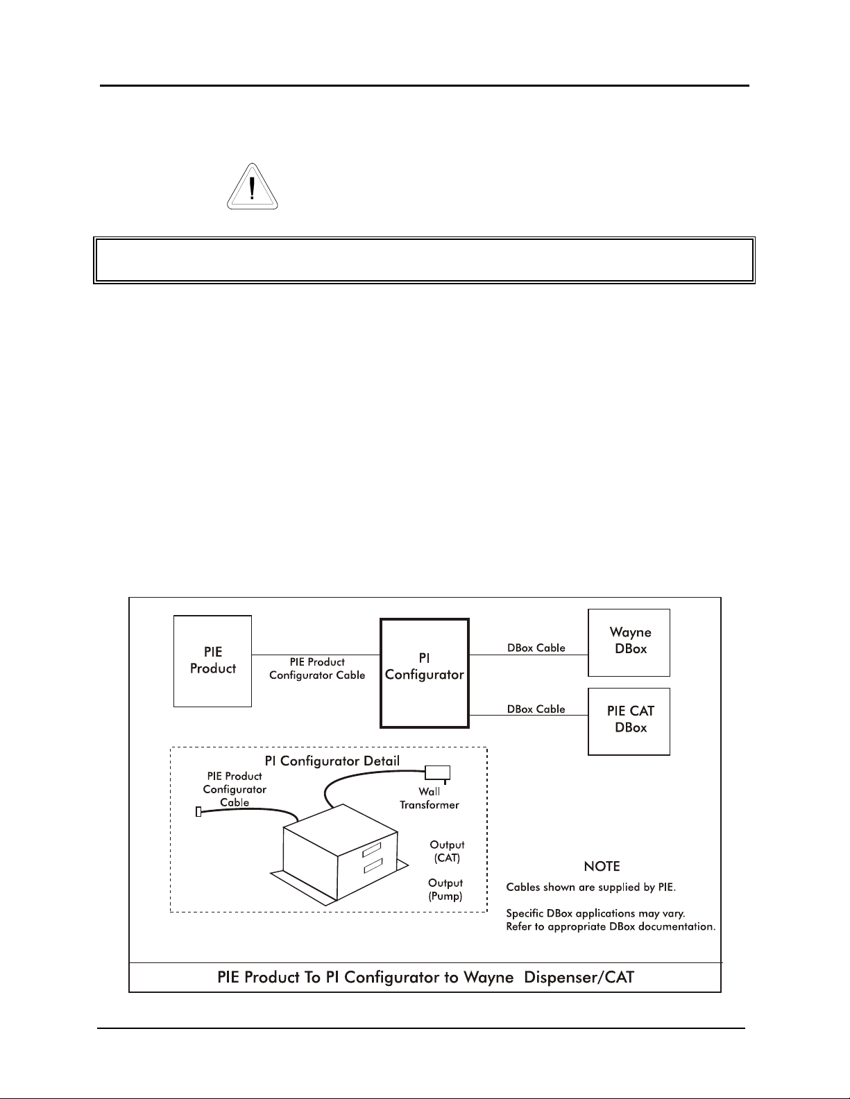
Wayne/Dresser CAT
Note all warnings at the beginning of installation section.
Instructions for DBox installations in this manual are for the specific DBoxes supplied by dispenser manufacturers. If using DBoxes
supplied by Progressive International, refer to the Installation Guide which accompanies PIE’s DBox.
Following instructions on preceding pages of installation section of this manual, install PCXZ,
configurator box(es) and dispenser. After successfully testing the dispensers using the PCXZ
system, then follow these specific instructions for connecting the Wayne/Dresser reader. See
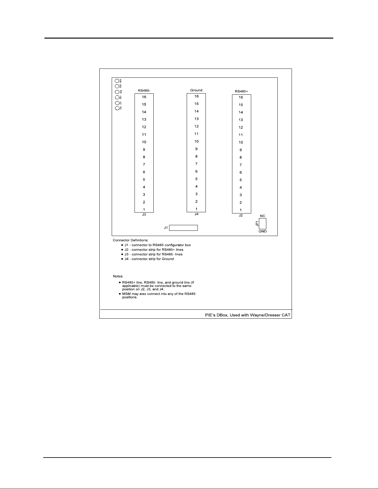
Diagram: Typical PCXZ Controller to Wayne/Dresser Dispenser/CAT and Diagram: DBox for Wayne/Dresser CAT
following this reader installation section.
1. Locate the reader connector on the PIE dual Wayne/Dresser configurator box. Plug the
appropriate cable supplied by PIE into this connector and plug the other end into the Wayne
CAT distribution box supplied by PIE. Connect all the existing Wayne/Dresser CAT’s into the
PIE RS485 DBox.
2. Return to the PCXZ Installation Section for remaining system installation procedures.
Diagram: PCXZ to Wayne/Dresser Electronic Dispenser/CAT
Version 4.2/April 2005 Page 11
PCXZinstall
Page 20
Progressive International Electronics PCXZ
Diagram: PIE’s DBox for Wayne/Dresser CAT
Version 4.2/April 2005 Page 12
PCXZinstall
Page 21
Progressive International Electronics PCXZ
System Installation
Dispenser & Reader Specific Installation
Tokheim Electronic Dispenser
Note all warnings at the beginning of installation section.
Instructions for DBox installations in this manual are for the specific DBoxes supplied by dispenser manufacturers. If using DBoxes
supplied by Progressive International, refer to the Installation Guide which accompanies PIE’s DBox.
PIE normally ships Tokheim-standard communications style configurators. A 67B DBox must be either converted or have appropriate
RS422 configurators and cable (supplied by PIE). If converting an RS422 67B DBox to Tokheim-standard communication, contact your
Tokheim representative.
Following instructions on preceding pages of installation section of this manual, install PCXZ and
configurator box(es). Then, follow specific instructions for connecting PCXZ system to the appropriate
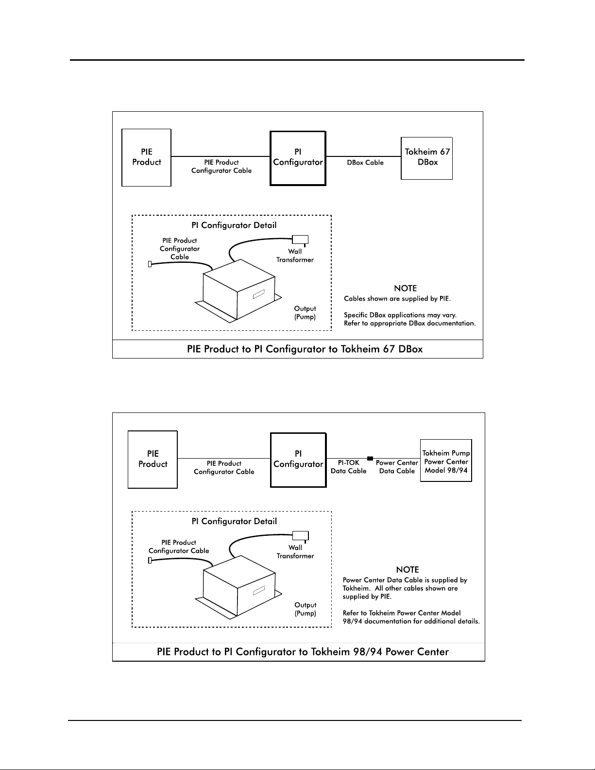
Tokheim DBox. Refer to Diagram: PCXZ to Tokheim 67 DBox and Diagram: PCXZ to Tokheim 98/94 Power Center following this
section and Diagram: PCXZ to Two Tokheim 98/94 Power Centers later in this section.
1. After installing the PCXZ, configurator box(es) and cabling according to the directions in this
document, follow Tokheim’s installation instructions and install dispensers.
For Dispensers Using Model 98/94 Computer/Power Center
(See next page for dispensers using Model 67 or 67B DBox.)
2. Install the Model 98/94 Computer/Power Center box according to Tokheim’s installation
manual. Dispensers must work in stand-alone before proceeding. Program dispensers as if connecting
to a Tokheim Model 179 or Model 184 Console.
3. Locate dispenser connection cable (with DB9S hooded connector on one end and a round
connector on the other end).
4. Connect the dispenser connection cable to the connector on the Tokheim configurator box.
Screw-lock this connector to the box with screws provided.
For systems with 8 dispensers or less — Connect the dispenser connection cable directly to
the Model 98/94 Computer/Power Center.
For systems with more than 8 dispensers (2 Model 98/94 Computer/Power Centers), —
Use a “Y” cable between the configurator box cable and the Model 98/94 Computer/Power
Centers.
Cables must be screw-locked together. The connection must be in a sheltered
environment, protected from harsh elements such as water, extreme heat or cold.
Version 4.2/April 2005 Page 13
PCXZinstall
Page 22
Progressive International Electronics PCXZ
For Dispensers Using Model 67 or 67B DBox
The 67 and 67B DBoxes are similar. Be sure to determine model number from
nameplate before attempting to connect to this device or damage may occur.
2. Connect wires to the 67 connection box according to Tokheim’s instructions. Program the
dispensers as though they were connected to a MIMS-IV.
3. Locate dispenser connection cable (with DB9S hooded connector on one end and a round
connector on the other end). Connect the dispenser connection cable to the connector on
the Tokheim configuration box.
Screw-lock this connector to the box with screws provided.
4. Locate the other end of the dispenser connection cable. Connect the round connector from
the PCXZ cable to the cable from the 67 DBox.
Cables must be screw-locked together. The connection must be in a sheltered
environment, protected from harsh elements such as water, extreme heat or cold,
etc.
5. If configuring for liter units, ensure that pump jumpers DA and DB at position JP1 are
installed. See Diagram: PCXZ Connector/Jumper Layout.
Version 4.2/April 2005 Page 14
PCXZinstall
Page 23
Progressive International Electronics PCXZ
Diagram: PCXZ to Tokheim 67 DBox
Diagram: PCXZ to Tokheim 98/94 Power Center
Version 4.2/April 2005 Page 15
PCXZinstall
Page 24
Progressive International Electronics PCXZ
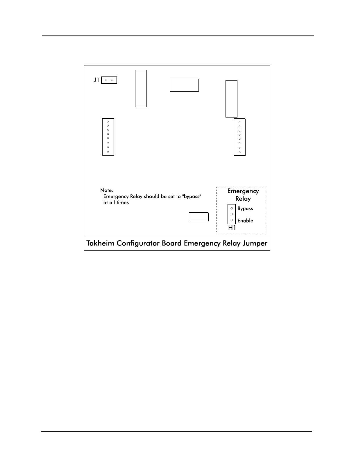
Diagram: Tokheim Configurator Board Emergency Relay Jumper
Version 4.2/April 2005 Page 16
PCXZinstall
Page 25
Progressive International Electronics PCXZ
System Installation
Dispenser & Reader Specific Installation
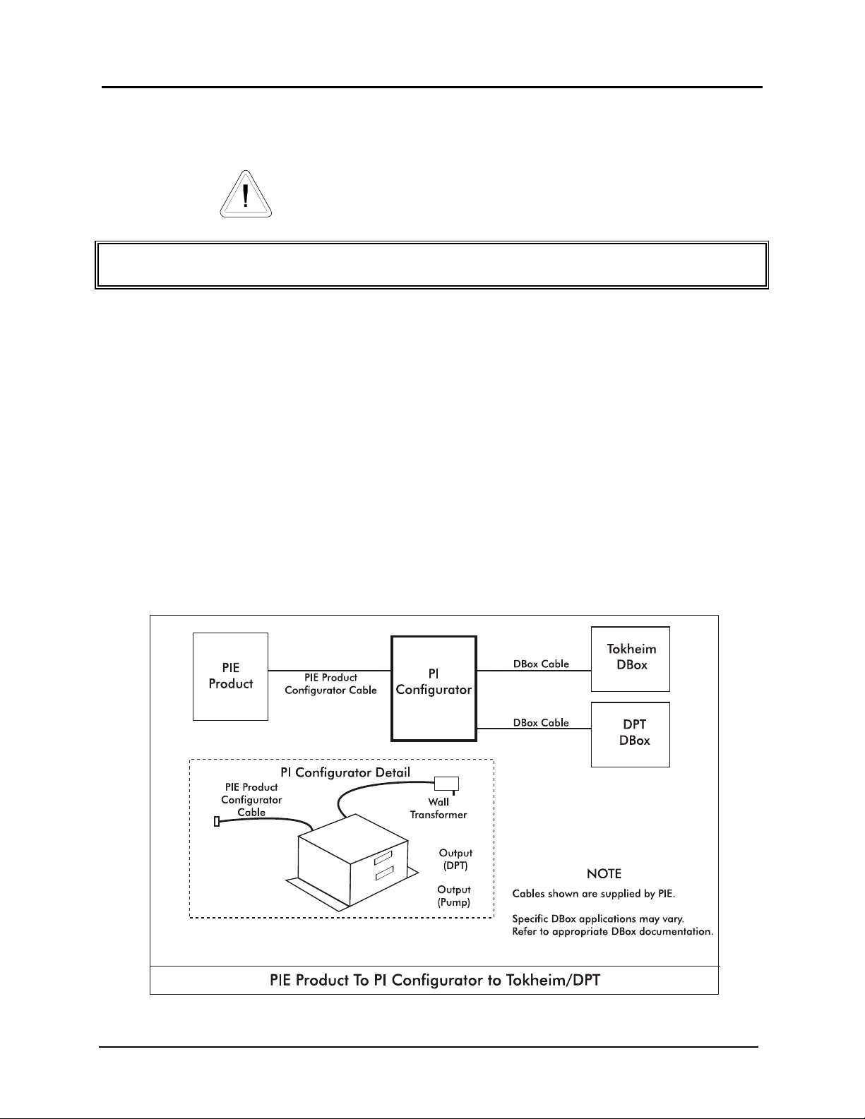
Tokheim DPT
Note all warnings at the beginning of installation section.
Instructions for DBox installations in this manual are for the specific DBoxes supplied by dispenser manufacturers. If using DBoxes
supplied by Progressive International, refer to the Installation Guide which accompanies PIE’s DBox.
Minimum dispenser software level supported is JP020800.
Following instructions on preceding pages of installation section of this manual, install PCXZ,
configurator box(es) and dispenser. After successfully testing the dispensers using the PCXZ system,
then follow these specific instructions for connecting the Tokheim reader. See Diagram: PCXZ to Tokheim
Dispenser/DPT which follows.
1. Locate the DPT connector on the PIE dual Tokheim configurator box. Plug the appropriate
cable supplied by PIE into this connector and wire the other end into the Tokheim 69
distribution box. Connect all the existing Tokheim DPT’s into the Tokheim 69 DPT DBox.
2. Return to the PCXZ Installation Section for remaining system installation procedures.
Diagram: PCXZ to Tokheim Dispenser/DPT
Version 4.2/April 2005 Page 17
PCXZinstall
Page 26
Progressive International Electronics PCXZ
System Installation
Dispenser & Reader Specific Installation
Schlumberger Electronic Dispenser
Note all warnings at the beginning of installation section.
Instructions for DBox installations in this manual are for the specific DBoxes supplied by dispenser manufacturers. If using DBoxes
supplied by Progressive International, refer to the Installation Guide which accompanies PIE’s DBox.
Following instructions on preceding pages of installation section of this manual, install PCXZ and
configurator box(es). Then, follow specific instructions for connecting PCXZ system to the
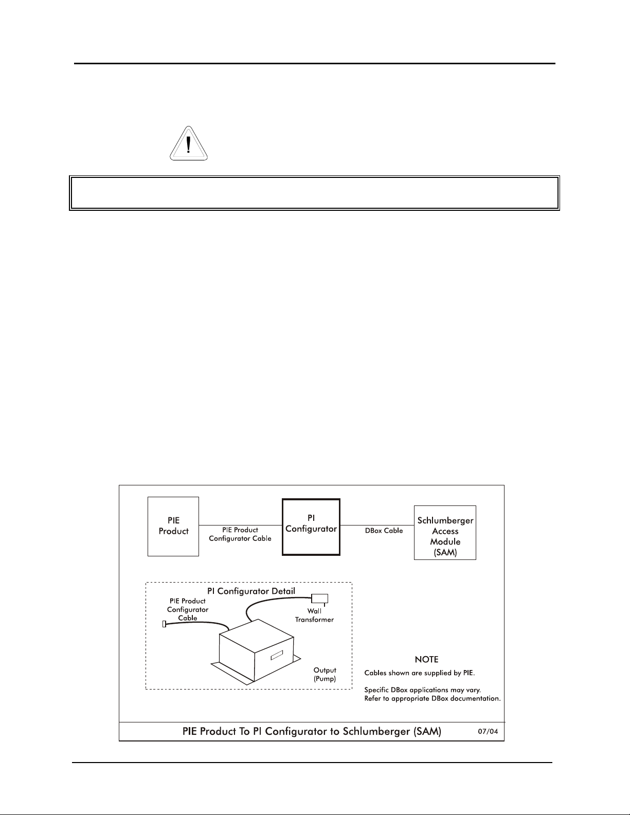
Schlumberger/SAM dispenser system. Refer to Diagram: PCXZ to Schlumberger Electronic Dispenser which follows.
1. First, make sure that the Schlumberger dispensers are attached to a Schlumberger Access
Module (SAM). The PCXZ controllers are designed to communicate and control
Schlumberger dispensers through the Schlumberger Access Module (SAM).
2. Connect the output of the PIE Schlumberger Configurator to the POS1 connector (dispenser
port) on the SAM with the cable provided by PIE.
3. For more reliable communication, ensure that SAM is set for 4800 baud for dispenser port
and RS232 config is set to 4800.
When programming the dispenser, refer to the Schlumberger Dispenser Option 98 Programming Example later in this section.
Diagram: PCXZ to Schlumberger Electronic Dispenser
Version 4.2/April 2005 Page 18
PCXZinstall
Page 27

Progressive International Electronics PCXZ
Schlumberger Electronic Dispenser Option 98
Programming Example
Schlumberger dispensers may be configured to operate in many different modes. Below is a listing of
the option programming in the dispenser that is necessary for correct operation with the PCXZ. These
parameters may be obtained by entering into the configuration mode on the dispenser, then
executing an option dump using option 98. Refer to Schlumberger dispenser programmer’s guide for instructions.
Option # Description Setting
01 Access Code 0
11 Paymode Control — DISABLE OTHER PAYMODE 0
12 CNG Dispenser Mode 0
13 Side 1 Satellite — NO SATELLITE UNIT 1
13 Side 2 Satellite — NO SATELLITE UNIT 2
14 Master & Satellite Flow Enabled — NO CONCURRENT FLOW 0
15 Display Board Type — ICON DISPLAY EQUIPPED 1
16 Enable Icons — DISPLAY ICONS ENABLED 1
17 Flash Cash/Credit — FLASHING ICONS DISABLED 0
18 Single Hose — MULTI-HOSE OPERATION 0
23 Dispenser Handle Debounce Time 025
24 Enable Presets — NO PRESET KEYBOARD 0
24 Enable Presets — NO PRESET KEYBOARD 0
25 Comm Mode — XPIC COMM SUPPORT 4
26 Card Reader/Printer Hardware — LEFT-UP HW INSTALLED 2
28 Pulser Type Single
29 Meter Type — GALLON METER INSTALLED 1
34 Max Flow Rate 0
36 Large Valve Prepay Slow Down Time — TIME IN SECONDS 0.200
37 Small Valve Prepay Slow Down Time — TIME IN SECONDS 0.000
38 Line Pressure Valve Delay 3.000
39 Flow Before Opening — LARGE VALVE 000
40 Amount of Flow Before Display Update — UNITS OF VOLUME 10
41 Num Prods-Side 1 3
41 Num Prods-Side 2 3
42 Num Pay Modes-Side 1 1
42 Num Pay Modes-Side 2 1
Side 2 Programming
Display Position 1
Dispenser Handle 1
Product 00
Base Product 1 00
Base Product 2 15
Meter/Valve Set 1 1
Meter/Valve Set 2 0
Sub-Dispenser 1 1
Sub-Dispenser 2 0
Version 4.2/April 2005 Page 19
PCXZinstall
Page 28

Progressive International Electronics PCXZ
Option # Description Setting
Display Position 2
Dispenser Handle 2
Product 01
Base Product 1 01
Base Product 2 15
Meter/Valve Set 1 2
Meter/Valve Set 2 0
Sub-Dispenser 1 2
Sub-Dispenser 2 0
Display Position 3
Dispenser Handle 3
Product 02
Base Product 1 02
Base Product 2 15
Meter/Valve Set 1 3
Meter/Valve Set 2 0
Sub-Dispenser 1 3
Sub-Dispenser 2 0
Display Position 4
Dispenser Handle 0
Product 15
Base Product 1 15
Base Product 2 15
Meter/Valve Set 1 0
Meter/Valve Set 2 0
Sub-Dispenser 1 0
Sub-Dispenser 2 0
43 PPU Display Assignment (Side 1 Programming)
Display Position 1
Dispenser Handle 1
Product 00
Base Product 1 00
Base Product 2 15
Meter/Valve Set 1 1
Meter/Valve Set 2 0
Sub-Dispenser 1 1
Sub-Dispenser 2 0
Display Position 2
Dispenser Handle 2
Product 01
Base Product 1 01
Base Product 2 15
Meter/Valve Set 1 2
Meter/Valve Set 2 0
Sub-Dispenser 1 2
Sub-Dispenser 2 0
Display Position 3
Dispenser Handle 3
Product 02
Base Product 1 02
Base Product 2 15
Version 4.2/April 2005 Page 20
PCXZinstall
Page 29

Progressive International Electronics PCXZ
Option # Description Setting
Meter/Valve Set 1 3
Meter/Valve Set 2 0
Sub-Dispenser 1 3
Sub-Dispenser 2 0
Display Position 4
Dispenser Handle 0
Product 15
Base Product 1 15
Base Product 2 15
Meter/Valve Set 1 0
Meter/Valve Set 2 0
Sub-Dispenser 1 0
Sub-Dispenser 2 0
44 Decimal Position — Sale $ Display 2
45 Decimal Position — Volume Display 3
46 Decimal Position — PPU Display 2
51 Time Out, Paymode or Product Button 030
52 Pulser Time Out 000
53 Time Between Sales 003
54 Price Change — Dead Time 000
55 8's Reset Delay 001
56 1's Reset Delay 001
60 Customer Display Line Length 16
61 Prepay Paymode Confirm
Side 1 Programming
Paymode 0 1
Paymode 2 1
Paymode 3 1
Paymode 4 1
Paymode 5 1
Paymode 6 1
Paymode 7 1
Side 2 Programming
Paymode 0 1
Paymode 2 1
Paymode 3 1
Paymode 4 1
Paymode 5 1
Paymode 6 1
Paymode 7 1
62 XPIE/Allied Primary Address 0
63 XPIC Allied Secondary Address 153
64 Enable Side 2 — SIDE 2 ENABLED 1
63 Restore Last Sale — RESTORE LAST SALE 1
66 Assign XPIC/Allied FP #
67 Enable Pmode Selection
68 Touchpad Type — CARD READER TOUCHPAD 1
69 Audible Prompting — PROMPT CUSTOMER W/ BEEP 5
Side 1
Side 2
Side 1 — PAYMODE SELECTION REQ'D
Side 2 — PAYMODE SELECTION REQ'D
01
02
1
1
Version 4.2/April 2005 Page 21
PCXZinstall
Page 30

Progressive International Electronics PCXZ
Option # Description Setting
72 Volume Limit by Product
73 Volume Limit by Paymode
74 Dollar Limit by Product
75 Dollar Limit by Paymode
76 Product Price/Pay Mode (Side 1 Prices)
Prod 0 Limit
Prod 1 Limit
Prod 2 Limit
Prod 3 Limit
Prod 4 Limit
Prod 5 Limit
Prod 6 Limit
Prod 7 Limit
PMode 0 Limit
PMode 1 Limit
PMode 2 Limit
PMode 3 Limit
PMode 4 Limit
PMode 5 Limit
PMode 6 Limit
PMode 7 Limit
Prod 0 Limit
Prod 1 Limit
Prod 2 Limit
Prod 3 Limit
Prod 4 Limit
Prod 5 Limit
Prod 6 Limit
Prod 7 Limit
PMode 0 Limit
PMode 1 Limit
PMode 2 Limit
PMode 3 Limit
PMode 4 Limit
PMode 5 Limit
PMode 6 Limit
PMode 7 Limit
Prod 0 Price
Prod 0 Price
Prod 0 Price
Prod 0 Price
Prod 0 Price
Prod 0 Price
Prod 0 Price
Prod 0 Price
Prod 1 Price
Prod 1 Price
Prod 1 Price
Prod 1 Price
Prod 1 Price
Prod 1 Price
Prod 1 Price
Prod 1 Price
Prod 2 Price
Prod 2 Price
Prod 2 Price
Prod 2 Price
Prod 2 Price
Prod 2 Price
Prod 2 Price
Prod 2 Price
Prod 3 Price
Prod 3 Price
Prod 4 Price
Prod 4 Price
Prod 5 Price
Prod 5 Price
Prod 6 Price
Prod 7 Price
999.990g
999.990g
999.990g
999.990g
999.990g
999.990g
999.990g
999.990g
999.990g
999.990g
999.990g
999.990g
999.990g
999.990g
999.990g
999.990g
$999.99
$999.99
$999.99
$999.99
$999.99
$999.99
$999.99
$999.99
$999.99
$999.99
$999.99
$999.99
$999.99
$999.99
$999.99
$999.99
$1.119
$1.119
$0.000
$0.000
$0.000
$0.000
$0.000
$0.000
$1.129
$1.129
$0.000
$0.000
$0.000
$0.000
$0.000
$0.000
$1.139
$1.139
$0.000
$0.000
$0.000
$0.000
$0.000
$0.000
$0.000
$0.000
$0.000
$0.000
$0.000
$0.000
$0.000
$0.000
Version 4.2/April 2005 Page 22
PCXZinstall
Page 31

Progressive International Electronics PCXZ
Option # Description Setting
76 (cont.) Product Price/Pay Mode(Side 2 Prices)
80 Debit Mode — DEBIT MODE DISABLED 0
85 Time Out, SAVR Err — TIME IN SECONDS 020
86 Paper Low Sensor — NO PAPER LOW SENSOR 0
Prod 0 Price
Prod 0 Price
Prod 0 Price
Prod 0 Price
Prod 0 Price
Prod 0 Price
Prod 0 Price
Prod 0 Price
Prod 1 Price
Prod 1 Price
Prod 1 Price
Prod 1 Price
Prod 1 Price
Prod 1 Price
Prod 1 Price
Prod 1 Price
Prod 2 Price
Prod 2 Price
Prod 2 Price
Prod 2 Price
Prod 2 Price
Prod 2 Price
Prod 2 Price
Prod 2 Price
Prod 3 Price
Prod 3 Price
Prod 4 Price
Prod 4 Price
Prod 5 Price
Prod 5 Price
Prod 6 Price
Prod 7 Price
$1.119
$1.119
$0.000
$0.000
$0.000
$0.000
$0.000
$0.000
$1.129
$1.129
$0.000
$0.000
$0.000
$0.000
$0.000
$0.000
$1.139
$1.139
$0.000
$0.000
$0.000
$0.000
$0.000
$0.000
$0.000
$0.000
$0.000
$0.000
$0.000
$0.000
$0.000
$0.000
87 SAM Mode — SAM MODE ENABLED 1
Version 4.2/April 2005 Page 23
PCXZinstall
Page 32
Progressive International Electronics PCXZ
System Installation
Dispenser & Reader Specific Installation
Shlumberger CardScan
Note all warnings at the beginning of installation section.
Instructions for DBox installations in this manual are for the specific DBoxes supplied by dispenser manufacturers. If using DBoxes
supplied by Progressive International, refer to the Installation Guide which accompanies PIE’s DBox.
Following instructions on preceding pages of installation section of this manual, install PCXZ,
configurator box(es) and dispenser. After successfully testing the dispensers using the PCXZ system,
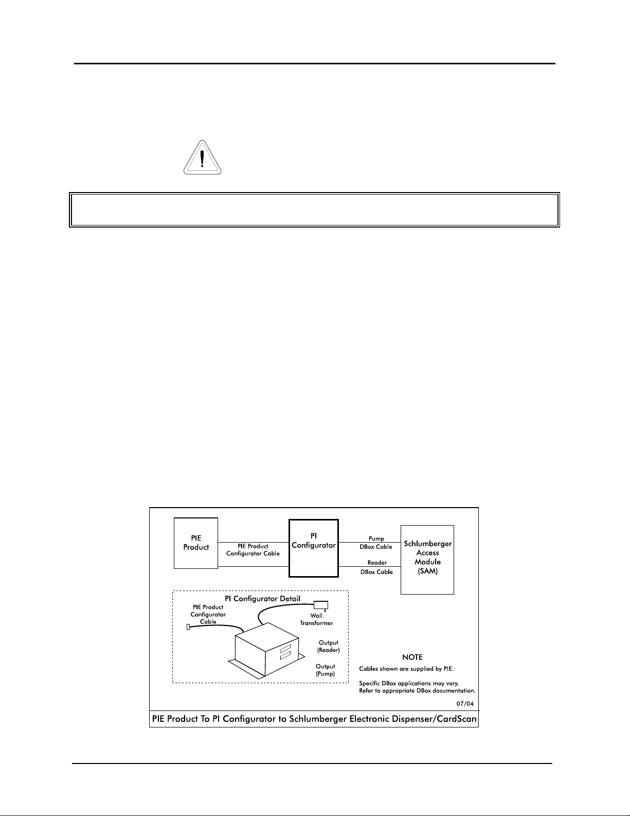
then follow these specific instructions for connecting the Schlumberger reader. See Diagram: PCXZ to
Schlumber Electronic Dispenser/CardScan which follows.
1. First, make sure that the Schlumberger dispensers are attached to a Schlumberger Access
Module (SAM). The PCXZ controllers are designed to communicate and control
Schlumberger dispensers/readers through the SAM.
2. Connect the reader output of the PIE Schlumberger configurator to the POS2 (reader port)
connector on the SAM with the cable provided by the PIE.
3. For more reliable communication, ensure that SAM is set for 4800 baud for dispenser port
and RS232 config ius set to 4800.
When programming the dispenser, refer to the Schlumberger Dispenser option 98 Programming Example in the preceding section.
Diagram: PCXZ to Schlumberger Electronic Dispenser/CardScan
Version 4.2/April 2005 Page 24
PCXZinstall
Page 33
Progressive International Electronics PCXZ
System Installation
Dispenser & Reader Specific Installation
Kraus Electronic Dispenser
Note all warnings at the beginning of installation section.
Instructions for DBox installations in this manual are for the specific DBoxes supplied by dispenser manufacturers. If using DBoxes
supplied by Progressive International, refer to the Installation Guide which accompanies PIE’s DBox.
The following Kraus models must have the minimum version of software noted to work properly with
Progressive equipment:
Micon 100
152 printed circuit board versions 3.1 & 3.2
252 printed circuit board version 6.30
463 PLCC processor version 7.03
Micon 200 version 1.09
Micon 300 version 2.04
Micon 500 to be announced
Following instructions on preceding pages of installation section of this manual, install PCXZ and
configurator box(es). Then, follow specific instructions for connecting PCXZ system to the appropriate
Kraus DBox.
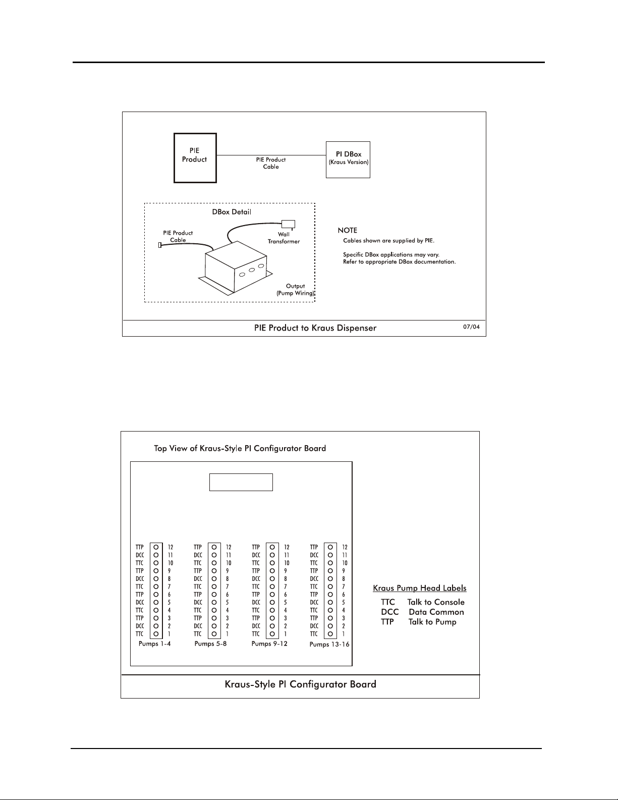
1. Connect the data communication wires from the Kraus dispenser into the dispenser
connectors on the PIE Kraus Configurator board. See Diagram: PCXZ to Kraus Electronic Dispensers which
follows. Note that there are three data communication wires connecting to a Kraus dispenser.
They are labeled as follows:
TTC Talk to Console/Kraus dispenser transmit data
TTP Talk to Dispenser/Kraus dispenser receive data
DDC Data Common / Kraus dispenser ground
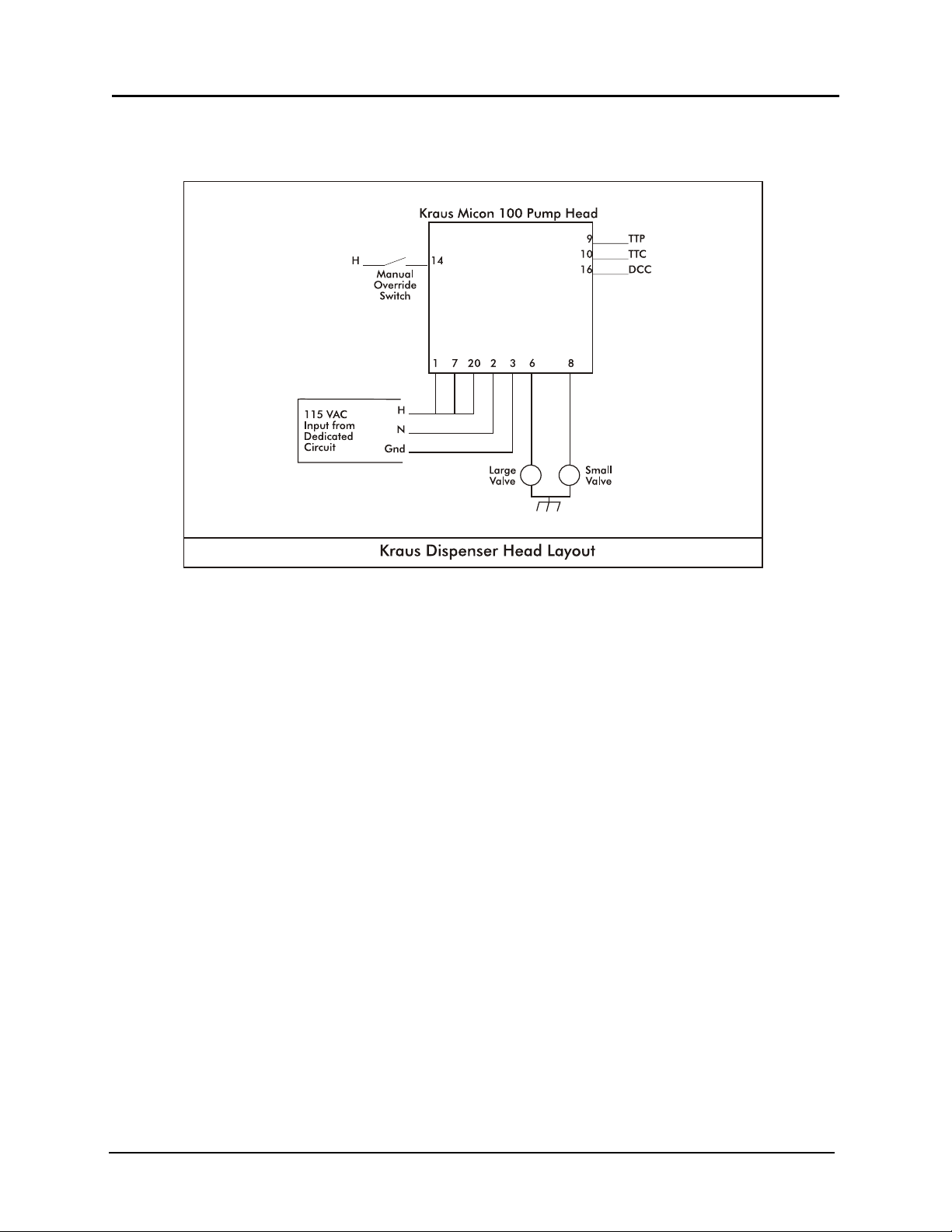
2. Note the layout of the Kraus dispenser head. Refer to Diagram: Kraus Dispenser Head Layout.
3. If submerged turbine dispensers are used, install according to Kraus dispenser installation
instructions or install optional PIE relay control box. See Diagram: Kraus Turbine Dispenser Layout at end of
this section.
Version 4.2/April 2005 Page 25
PCXZinstall
Page 34
Progressive International Electronics PCXZ
Diagram: PCXZ to Kraus Electronic Dispensers
Diagram: Kraus Configurator Board
Version 4.2/April 2005 Page 26
PCXZinstall
Page 35
Progressive International Electronics PCXZ
Diagram: Kraus Dispenser Head Layout
Version 4.2/April 2005 Page 27
PCXZinstall
Page 36
Progressive International Electronics PCXZ
System Installation
Dispenser & Reader Specific Installation
Bennett Electronic Dispenser
Note all warnings at the beginning of installation section.
Instructions for DBox installations in this manual are for the specific DBoxes supplied by dispenser manufacturers. If using DBoxes
supplied by Progressive International, refer to the Installation Guide which accompanies PIE’s DBox.
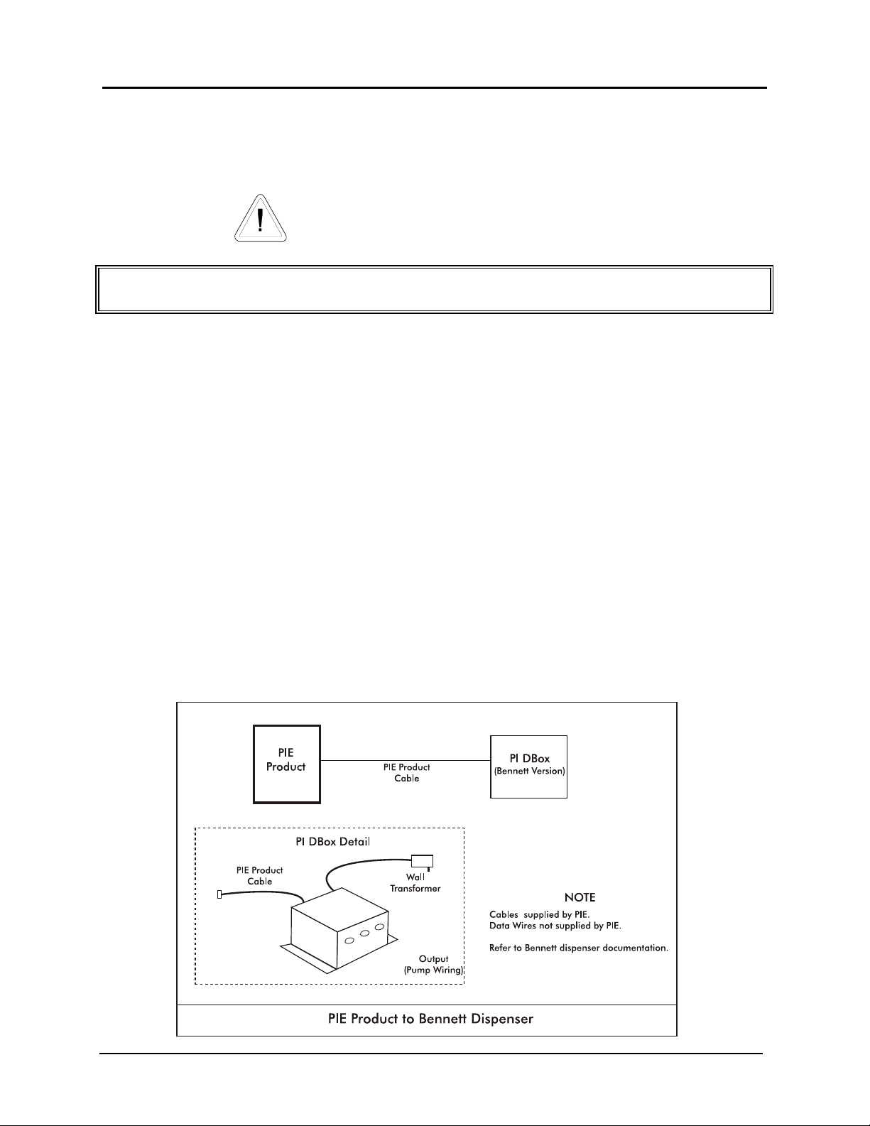
Following instructions on preceding pages of installation section of this manual, install PCXZ and
configurator box(es). Then, follow specific instructions for connecting PCXZ system to the Bennett
dispensers. Refer to Diagram: PCXZ to Bennett Electronic Dispensers.
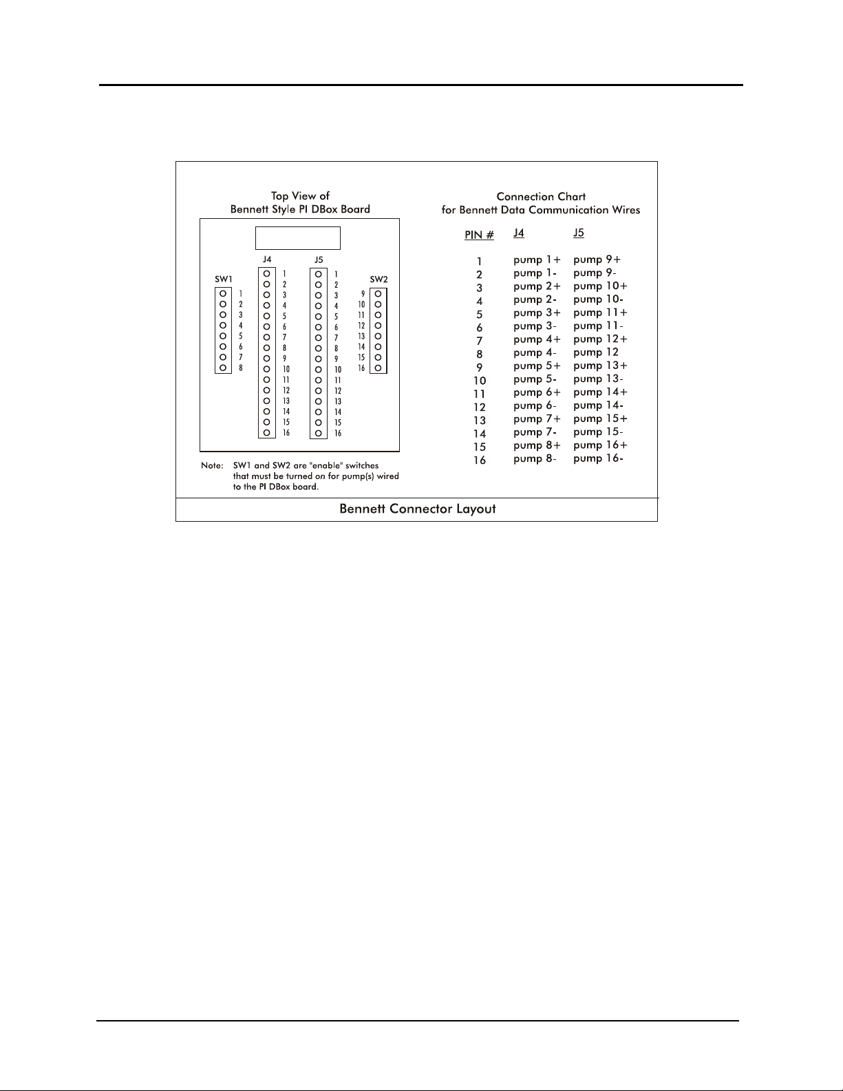
1. Connect the data communication wires from the Bennett dispensers (Orange [+] and Yellow
[-]) into the dispenser connectors (J4 & J5) on the Bennett Configurator Box provided by PIE.
See Diagram: Bennett Connector Layout.
2. Locate the communication enable dip switches (SW1 & SW2) on the Bennett Configurator
Box. Beginning with dispenser #1, turn on the #1 dip switch. Test the Dispenser 1 position
for correct operation as described in the general installation section. Continue this process
for all dispensers that exist at the site. When this installation procedure is complete, a dip
switch should be turned on for each position that has a dispenser wired to it. It is important
that only connected dispensers be switched on. All unused positions must be switched off.
Refer to Diagram: Bennett Connector Layout.
Diagram: PCXZ to Bennett Electronic Dispensers
Version 4.2/April 2005 Page 28
PCXZinstall
Page 37
Progressive International Electronics PCXZ
Diagram: Bennett Connector Layout
Version 4.2/April 2005 Page 29
PCXZinstall
Page 38
Progressive International Electronics PCXZ
System Installation
Dispenser & Reader Specific Installation
Tatsuno Electronic Dispenser
Note all warnings at the beginning of installation section.
Instructions for DBox installations in this manual are for the specific DBoxes supplied by dispenser manufacturers. If using DBoxes
supplied by Progressive International, refer to the Installation Guide which accompanies PIE’s DBox.
Following instructions from installation section of this manual, mount PCXZ and configurator box(es).
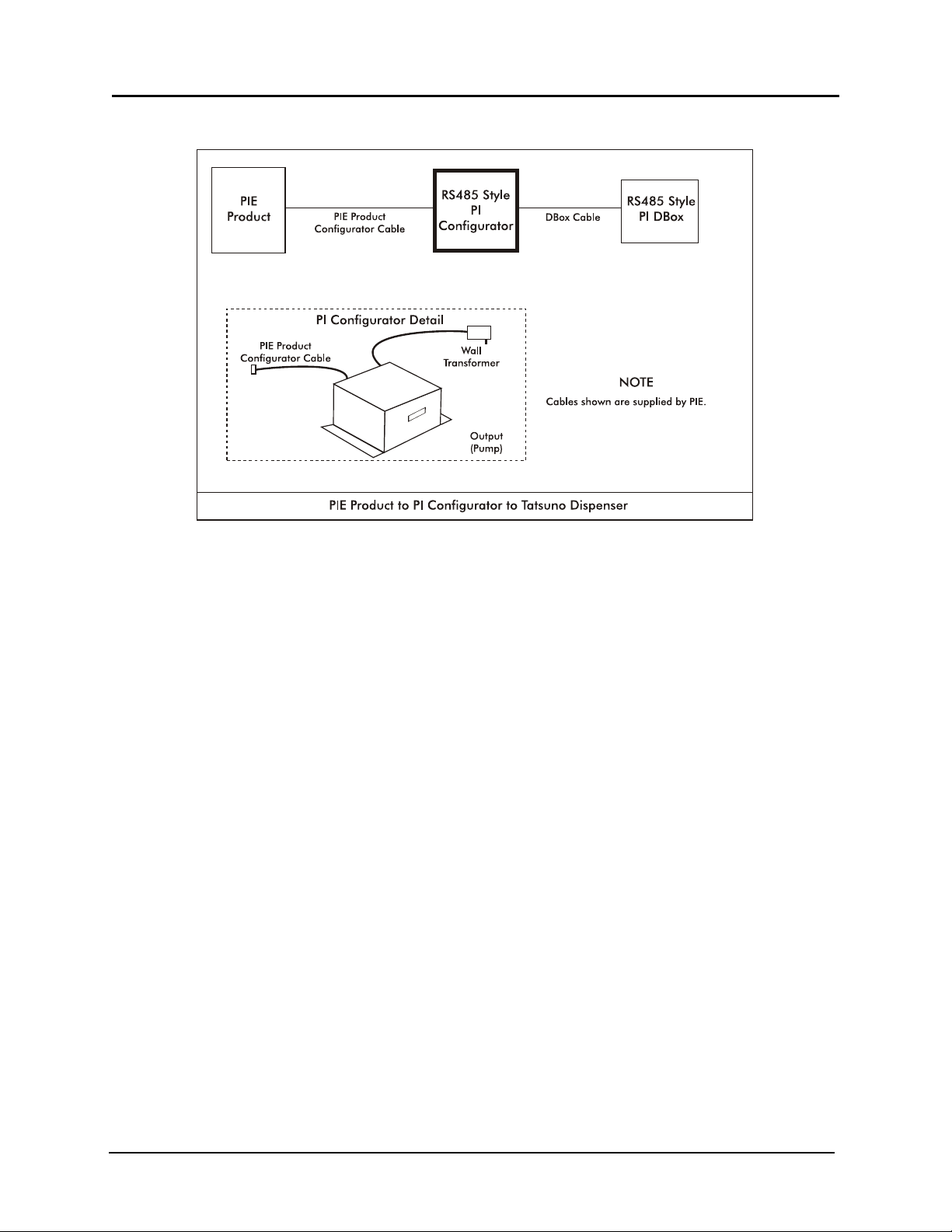
Then, follow specific instructions for connecting PCXZ system to the Tatsuno dispensers. Refer to the PIE
RS485 DBox Connections diagram following this section.
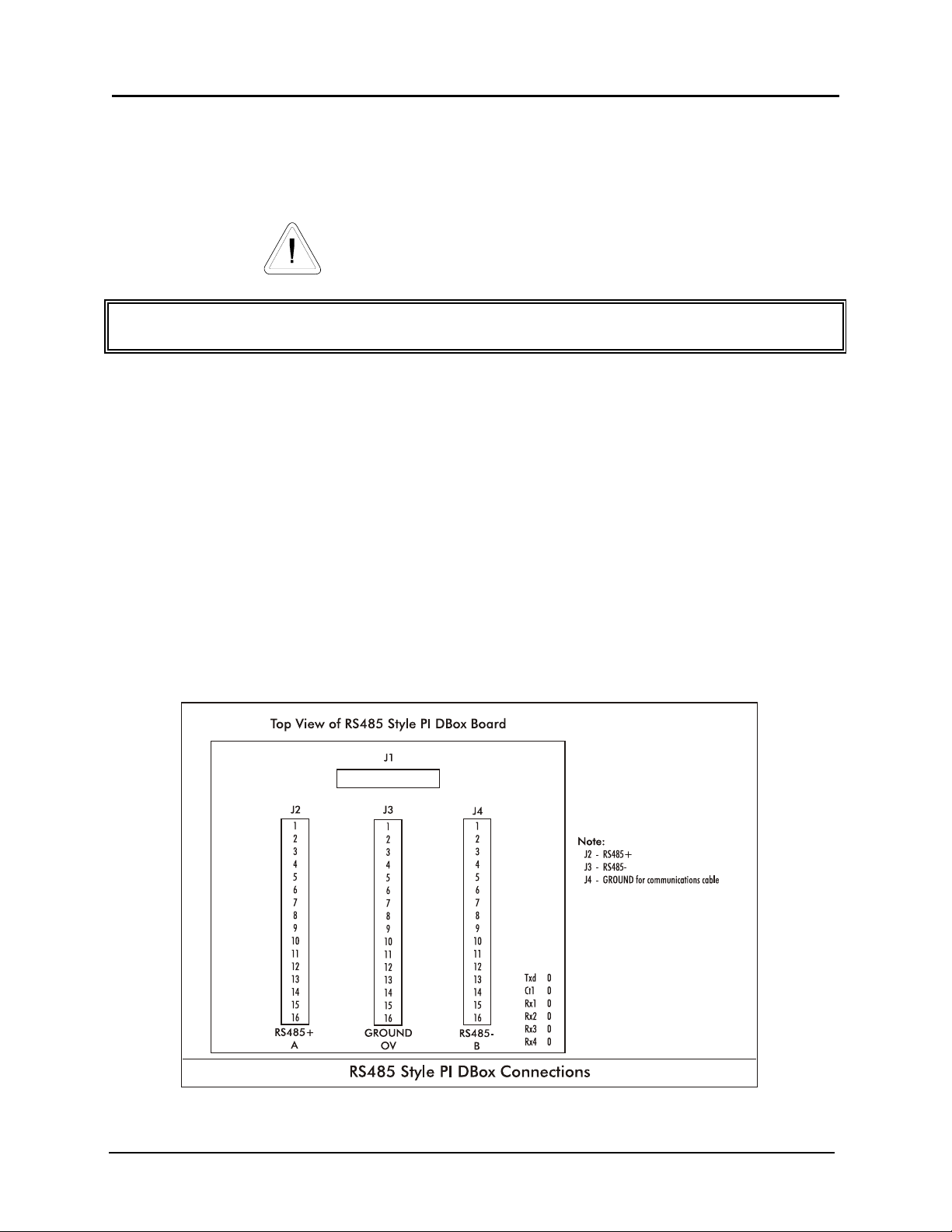
1. Connect the RS485 style configurator box to the RS485 DBox using the appropriate cable
supplied by PIE.
2. Connect the Tatsuno RS485 communication lines from each dispenser to the PIE RS485 DBox
board. Refer to Diagram: PIE RS485 DBox Connections and Diagram: PCXZ to Tatsuno Electronic Dispenser which follow.
3. Return to the PCXZ Installation Section for remaining system installation procedures.
Diagram: PIE RS485 DBox Connections
Version 4.2/April 2005 Page 30
PCXZinstall
Page 39
Progressive International Electronics PCXZ
Diagram: PCXZ to Tatsuno Electronic Dispensers
Version 4.2/April 2005 Page 31
PCXZinstall
Page 40
Progressive International Electronics PCXZ
System Installation
Dispenser & Reader Specific Installation
Nuovo Pignone Electronic Dispenser
Note all warnings at the beginning of installation section.
Instructions for DBox installations in this manual are for the specific DBoxes supplied by dispenser manufacturers. If using DBoxes
supplied by Progressive International, refer to the Installation Guide which accompanies PIE’s DBox.
Following instructions from installation section of this manual, mount PCXZ and configurator box(es).
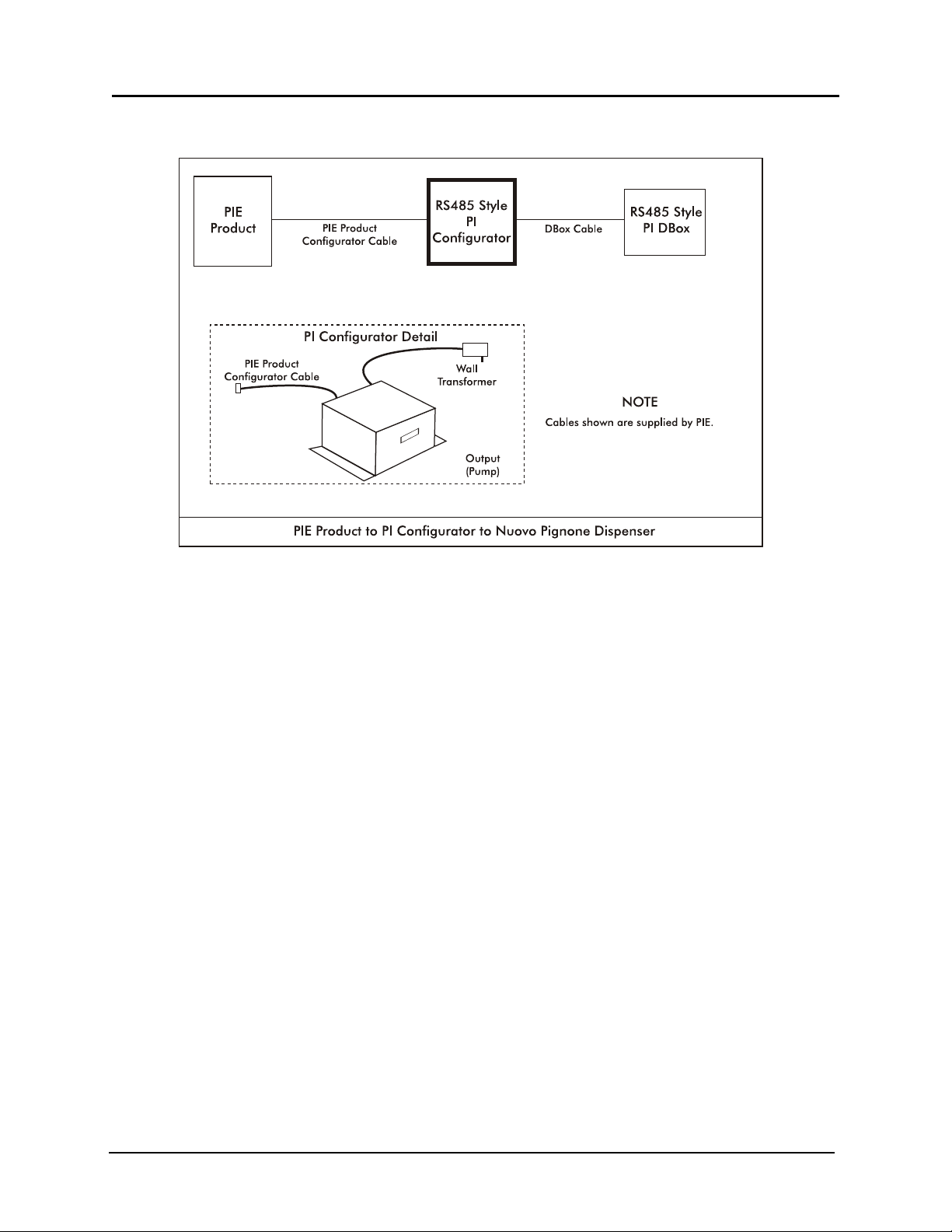
Then, follow specific instructions for connecting PCXZ system to the Nuovo Pignone dispensers. Refer
to the PIE RS485 DBox Connections diagram following this section.
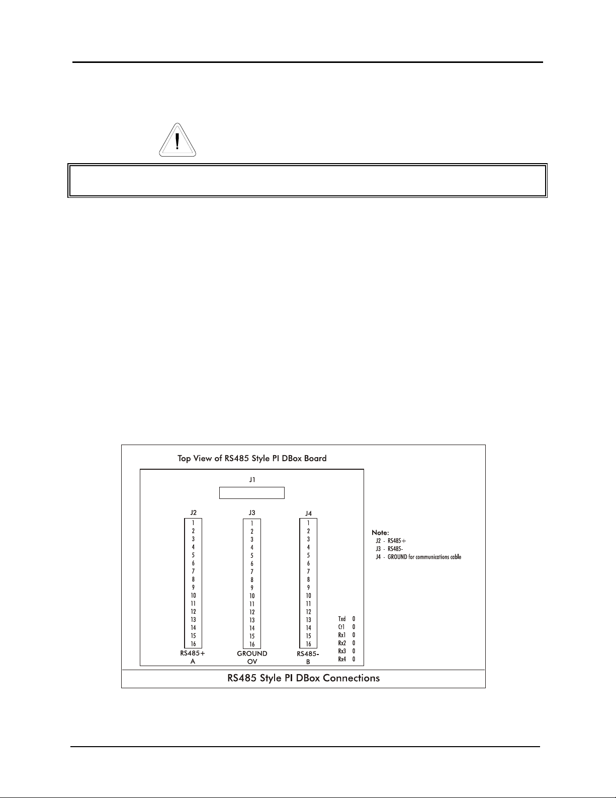
1. Connect the RS485 style configurator box to the RS485 DBox using the appropriate cable
supplied by PIE.
2. Connect the Nuovo Pignone RS485 communication lines from each dispenser to the PIE
RS485 DBox board. Refer to Diagram: PIE RS485 DBox Connections and Diagram: PCXZ to Nuovo Pignone Electronic
Dispenser which follow.
3. Return to the PCXZ Installation Section for remaining system installation procedures.
Diagram: PIE RS485 DBox Connections
Version 4.2/April 2005 Page 32
PCXZinstall
Page 41
Progressive International Electronics PCXZ
Diagram: PCXZ to Nuovo Pignone Electronic Dispensers
Version 4.2/April 2005 Page 33
PCXZinstall
Page 42
Progressive International Electronics PCXZ
Diagnostics
PCXZ Internal Diagnostics
The PCXZ controllers have on-board diagnostics which are helpful in solving problems encountered
in the field. Below are a few of the standard diagnostic functions built into the controller.
!
Show Dispenser Information
! Version Numbers
! Monitor A Port
To access this feature, all you need is a terminal or a computer running terminal emulation software
such as Procomm or Hyperterm for Windows. The diagnostic port is a serial port with the following
connection parameters. Note: A standard 9 pin serial cable is used to connect the terminal device to the diagnostic port, not a null
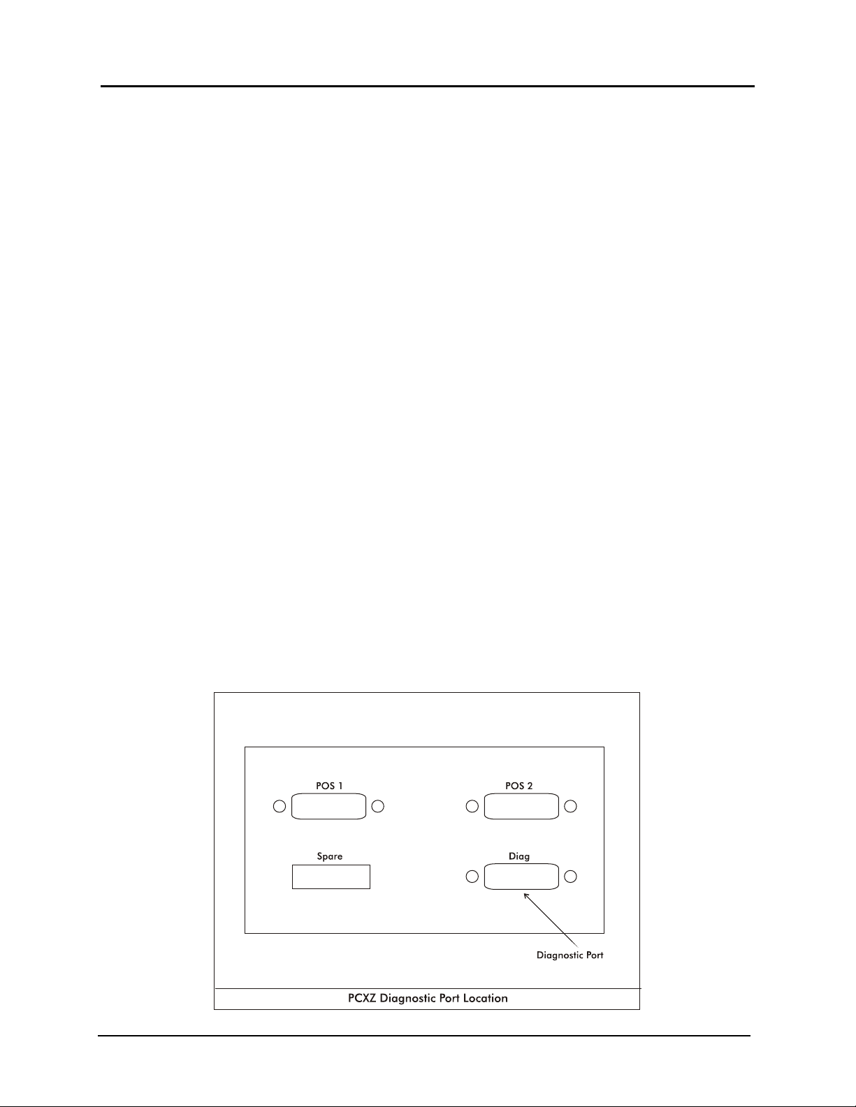
modem cable. See the diagrams on the following pages for connector locations.
! Baud Rate 19,200
! Data Bits 8
! Parity No
! Stop Bits 1
! Flow Control No
After connecting to the diagnostics port, power up the controller, type a question mark (?), and press
enter. A menu will appear, displaying the various diagnostic functions available. To select a
function, type the letter shown in the menu and press enter. Some features will prompt for additional
information. To exit a diagnostic function, press the escape key. The display will show a dash line
waiting for another command from the user. Any time a prompt ( >) dash line is shown, a question
mark may be entered to display the menu.
Diagram: PCXZ Diagnostic Port Location
–
Version 4.2/April 2005 Page 34
PCXZinstall
Page 43

Progressive International Electronics PCXZ
Diagnostics
Dispenser Control Center Demo Test Program
Progressive International Electronics’ PCC Demo Test Program simulates a generic POS application
program. It may be used for both demonstrations and field diagnostics. The PCC Demo Test
Program is provided on the same disk as the Dispenser Simulator Program, and is loaded on a
second computer.
Loading the PCC Demo Test Program
For the PCC Demo Test Program to operate correctly, the ANSI.SYS screen driver must also
be loaded on the computer. If this driver is not installed, locate the ANSI.SYS file on your
computer, add the following line to the CONFIG.SYS file and reboot the computer.
DEVICE=C:\[path]\ANSI.SYS
The programs on the distribution disk should be copied into a subdirectory on the hard drive.
This may be accomplished by creating a subdirectory (i.e., PCC) and copying all the files to
the subdirectory. The files to be copied to the subdirectory are as follows.
PCC.EXE
PCC_SERL.EXE
SYSTEM.DAT
To start the PCC program, first execute the DOS TSR driver for the controller. The driver used
for Progressive’s controllers is:
Next, execute PCC.EXE.
Main Screen
F1 = Help
F2 = Set up the PC port
F3 = Operator mode
F4 = Program mode
F5 = Read the error
F6 = Reset the PCC
F7 = Set printer
F9 = Set screen
F10 = Exit to DOS
Select the Function:
PCC_SERL
(sets Comm 1, 9600 baud, INT Vector 60)
PCC_SERL P2F8 i3
(sets Comm 2, 9600 baud, INT vector 60)
For extended settings for PCC_Serl, view the readme.txt file on the PCC Demo Disk.
Version 4.2/April 2005 Page 35
PCXZinstall
Page 44

Progressive International Electronics PCXZ
F4 Screen — Program Mode
F4 should be performed first in order to set up the system prices for each dispenser (fueling
position) and hose. The F4 screen is as follows.
Cash PPU Credit PPU Blend Ratio
Hose #1 0.000 0.000 000
Hose #2 0.000 0.000 000
Hose #3 0.000 0.000 000
Hose #4 0.000 0.000 000
Hose #5 0.000 0.000 000
Hose #6 0.000 0.000 000
Hose #7 0.000 0.000 000
Key in the cash and credit PPU according to dispenser number and hose number.
F2 Screen — Set Up the PC Port
Once the prices have been programmed, press F2 to connect the DOS TSR driver and to
start the communication with the controller. To use the default of 60, press the ENTER key.
The F2 screen appears as below.
F3 Screen — Operator Mode
F3 brings up the operator screen, in which the dispensers are controlled. As fuel is
dispensed, the dollar value and the volume dispensed will appear on the screen. The screen
appears as below.
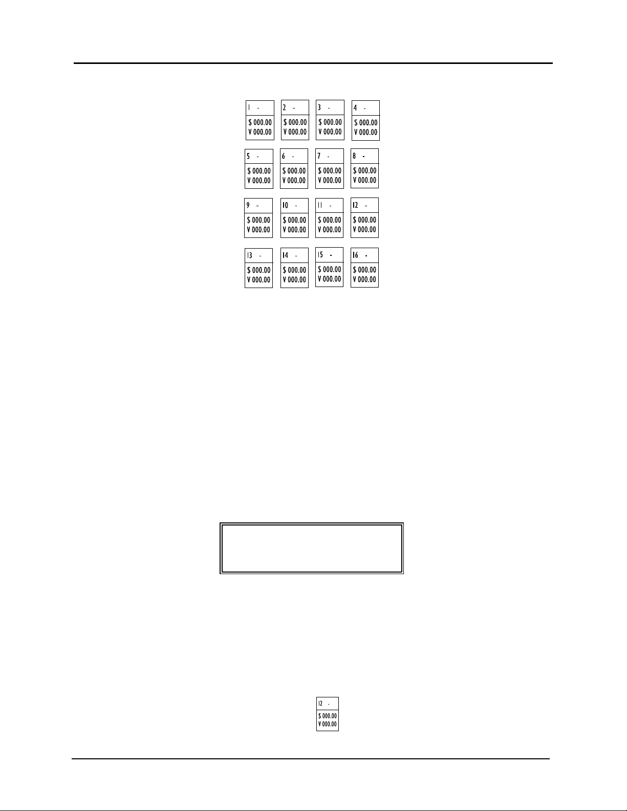
F1 = Help F2 = Dispenser #
F3 = (E)Stop F4 = (A)Resume
F5 = Collect F6 = Grade #
F7 = Preset $ F8 = Authorize
F9 = Totals F10 = Exit
PGDN = Next Dispenser HOME = Dispenser 1
PGUP = Prev Dispenser END = Dispenser 32
Set up the PC port
(Press enter for a default of 60)
Enter the driver interrupt number (HEX):
Operator Control
Version 4.2/April 2005 Page 36
PCXZinstall
Page 45
Progressive International Electronics PCXZ
System ST: 00
F5 Screen — System Error
If a system error occurs, it may be read by pressing F5. The screen is as follows.
F7 Screen — Set Printer
Perform F7 to enter a Print Header. This screen will appear.
F9 Screen — Set Screen
F9 changes screen colors. The following screen will appear.
Press the F10 key to clear all errors and exit or
Press any key to continue
CR
The header has been cleared
Select the screen colors
the current colors are
Version 4.2/April 2005 Page 37
PCXZinstall
Page 46

Progressive International Electronics PCXZ
Diagnostics
Command Structure for Downloading
PCXZ Downloadable Controllers
The download function must be implemented before loading TSR.
PIE’s PCXZ series of controllers consists of two versions, ROM and downloadable. The downloadable
version is designed to allow the dispenser and credit card reader software to be downloaded directly
from the POS terminal into the PCXZ. This feature eliminates the need to change EPROMs for each
dispenser brand.
The enclosed diskette contains the BIN files necessary for each dispenser type supported by PIE.
These BIN files may be downloaded individually. For your convenience, batch files (.BAT) for the
most common dispenser brands are also provided, allowing the user to load all necessary files to the
controller with one command (i.e., DL_GIL). See Brand-Specific Batch Files later in this section.
The entire download process takes less than two minutes. Files will only need to be downloaded
once since they remain resident in an area of memory protected by battery backup. New controllers
ordered will be loaded with the dispenser software specified on the order and should not require
reloading.
The enclosed diskette also contains the test programs PIE offers for troubleshooting and
demonstration. (It should be left with the store manager for future use.) These programs are
PCC.EXE for non-reader dispensers and PCCR.EXE for dispensers with CRINDs. The following
equipment is required to run these programs and the download:
Laptop computer or PC running DOS (not DOS shell)
1 to 1 RS232 serial cable
Diskette provided by PIE
PCXZ and cables
Download Format
Below is the format used by the download program to send software to the PCXZ. Descriptions of the
switch parameters are also listed.
Download fn.typ [Comm port] [bank code] [type code]
i.e., Download Pos.Bin 1 0 c
Comm Ports
1 - 4 => Comm 1 -> Comm 4
Additional Ports
A = 0x2AB
B = 0x3AB
C = 0x2BB
D = 0x3BB
Version 4.2/April 2005 Page 38
PCXZinstall
Page 47

Progressive International Electronics PCXZ
Banks
0 = POS
1 = PC/CC1
2 = PC/CC2
3 = Dispenser 1-16
4 = Card 1-16
5 = Dispenser 17-32
6 = Card 17-32
Type
C = Clear all code banks first
A = Append bank (do not reset)
E = Reset controller when done
The process of downloading configuration files to the PCXZ may be accomplished by following either
of the sequences listed below:
1. Insert diskette into drive (A: or B:). The prompt should be either A:\ or B:\.
2. Type “Download POS.BIN [Comm Port] [Bank Code] [Type Code]” (i.e., Download POS.BIN
1 0 C)
3. Continue to download all necessary dispenser and card information (if required) to the
appropriate banks.
OR
Type “DL_xxx y” where xxx is the dispenser type and y is the destination Comm Port. This is
the format for using one of the batch files which loads all appropriate files into the
corresponding bank. The actual files from the diskette provided by PIE are listed below.
These formats are used by the download program to send software to the PCXZ
Brand-Specific Batch Files
dl_gil. bat for Gilbarco
dl_dw.bat for Wayne/Dresser
dl_tok.bat for Tokheim
dl_sam.bat for Schlumberger
dl_krs.bat for Kraus
dl_ben.bat for Bennett
dl_gen.bat for generic dispensers
The download feature also allows different dispenser and card reader types to be loaded into the
same controller. For example, a site may have Gilbarco dispensers on one island and Tokheim
dispensers on another. The Gilbarco dispenser would be loaded into bank 3 and the Tokheim
dispenser into bank 5. If these dispensers have card readers, the files would be loaded into bank 4
for Gilbarco and bank 6 for Tokheim. The files may be loaded in any order to accommodate the
specific requirements of the user.
Version 4.2/April 2005 Page 39
PCXZinstall
Page 48

Progressive International Electronics PCXZ
Diagnostics
PCXZ General Diagnostics
Due to the complex and hazardous nature of servicing dispensing control systems, you should
contact your POS dealer/distributer for technical support. They are responsible for first level of
support on their products.
Dispensers and other fuel handling equipment should always be installed and serviced by a
certified dispenser mechanic. This type of equipment is extremely hazardous if not handled
properly.
On the following pages are some typical oversights or problems which may prevent proper operation
with the PCXZ, regardless of the brand of dispenser/card reader. While dispensers vary drastically
from brand to brand and model to model, there are issues common to all dispensers. Before
proceeding to the troubleshooting steps for your particular brand of dispenser, go through this
checklist.
For additional diagnostic tools, visit our web site at www.pie-corp.com
General Testing Procedures
T CHECK IT OUT!
T Are dispenser/reader IDs set properly? Most brand dispensers and their card readers must
have unique numbers — the dispenser/reader ID — set to identify each individual
dispenser/reader. A common problem occurs when the ID for a dispenser/reader is set the
same as for another dispenser/reader. Also, on new dispensers/readers, the manufacturer
usually sets IDs to a default value. If they are not changed, then all dispensers/readers will try
to answer at the same time, causing communications errors.
T Are cable connections secure? Check all cables from POS to dispensers/readers to ensure
that the connections are secure before applying power to any equipment. Crossed wiring for
both power and communications can cause erroneous operation as well as possible damage
to system components.
T Is the dispenser in manual override mode? Dispensers may be put in a manual override
mode to allow the dispenser to operate as if no control system is connected to it. The
dispenser in manual is capable of dispensing any time the handle is lifted off-hook. A
dispenser in manual mode will not operate correctly with a controller such as the PCXZ. For
operation with the PCXZ, be sure dispenser is in console control mode.
Version 4.2/April 2005 Page 40
PCXZinstall
Page 49

Progressive International Electronics PCXZ
T Have you run PIE’s diagnostics? Often when a dispenser/reader site is being upgraded with
a POS using our PCXZ, the dispensers and readers may have existing problems keeping them
from performing 100%. Don’t assume all problems during a POS start-up installation are
POS related. PIE supplies two simple diagnostic tools to help determine the location of the
problem — 1) PCC Demo Test Program, an external software utility, and 2) PCXZ built-in
diagnostic functions, accessed through the diagnostic port. See Dispenser Control Center Demo Test
Program and PCXZ Internal Diagnostics at the beginning of this section.
T Have dispensers/readers been initialized correctly? Some dispensers/readers behave
erratically when power-cycled during an installation or upgrade. You may need to power
down the dispensers/readers, wait 30 seconds, then power up the dispensers/readers to
initialize them correctly.
T Have counter-balances been implemented to identify erroneous hose totals? Some
dispensers may return erroneous hose totals or even no totals at all. It is recommended that
the POS application software generate its own running totals in addition to the dispenser
polled totals in case there are problems of this nature.
T Have new dispenser/reader batteries been installed? Dispensers/readers have a battery
backup system to allow them to retain setup information in case of a power failure.
Unfortunately the batteries in the dispenser are rarely replaced and therefore setup
information, such as dispenser/reader IDs, are lost during a power glitch. Many problems
can result from dead batteries, including the two immediately preceding this one.
T Is there fuel in all tanks? Are leak detectors falsely tripping? Make sure that there is fuel in
the tanks at the site for all products. Also, leak detectors on the submersible dispenser can
falsely trip, causing the dispenser to dispenser slowly or not at all. These two hydraulic
problems occur more frequently than one would believe. It always pays to check the obvious.
T Have circuit breakers been tripped or turned off? There are many circuit breakers at a
fueling site that control power to all the components of the dispensing system — POS,
controllers, DBoxes, dispensers/readers, submersible dispenser, etc. If any of these breakers
are tripped or turned off, the performance of the entire dispensing system is affected.
Furthermore, these breakers may be located in different places throughout the facility.
T Have you tested, using a step-by-step approach? The startup of a new installation can
present all kinds of problems that exhibit seemingly illogical situations. Multiple, layered
problems may exist, complicating the diagnosis. At this point it is wise to try to work with a
small portion of the site equipment, get that running correctly, then add additional equipment
to the overall system, step by step. As an example of this approach, try running only one
dispenser (such as dispenser ID 1) with the PCXZ controller and the PCC DEMO program.
Once this step has been completed successfully, continue to put additional dispensers in the
system. After all dispensers are responding correctly using this setup, exit the PCC DEMO
program and bring the POS application online. This approach will provide a way to
determine which problems exist and where they are located.
Version 4.2/April 2005 Page 41
PCXZinstall
Page 50

Progressive International Electronics PCXZ
Preparation for Tech Support Calls
Should you require assistance from PIE regarding a problem with the PCXZ controller, be sure to
have the following information ready. This information is necessary in resolving controller-related
problems. PIE’s operating hours are Monday through Friday, 8:00 - 5:00 EST.
Is this a new installation or an existing site? If dealing with an existing site, how old?
Brand of dispensers and readers.
Model numbers of all dispensers and readers.
Number of dispensers and readers.
Model numbers of distribution boxes (DBoxes).
If site layout is complex, draw a site layout diagram labeling individual components and fax to
PIE for reference (919 821-1325).
Version of software in the dispensers, card readers, and PIE controller.
Frequency of problem — does it happen once a day or on all transactions, on one dispenser
or all dispensers, etc.
Find out if the problem with the dispenser/readers can be correlated with an event such as a
loss of power, a lightning storm, a dispenser/reader repair/servicing, a software upgrade to
one of the system components, etc.
Results of running the PIE supplied test utilities such as PCC DEMO.
Results of diagnostic port information on the PCXZ.
Version 4.2/April 2005 Page 42
PCXZinstall
Page 51

Progressive International Electronics PCXZ
Diagnostics
Troubleshooting Procedures
Gilbarco Dispenser/CRIND
In addition to the general diagnostic procedures that should be employed when troubleshooting a
fuel system, there are some unique considerations when working with Gilbarco dispensers and
readers.
DBox Configuration. Gilbarco uses several electrical interfaces for communications to and from the
dispenser, such as two-wire interface (TWI) and RS422. The distribution box must match the PIE
configurator ordered for the system. Both the Gilbarco Universal DBox and PIE’s DBox can be set up
as either a TWI or RS422 box and can easily be changed in the field. Refer to the appropriate DBox manual
for configuration information.
TWI Current Level. Current level needs to be 45mA on Gilbarco DBoxes using TWI communication.
The signal current is generated by the PIE configurator box. Occasionally this current level needs to
be set to accommodate the Gilbarco DBox input circuitry. See Diagram: PCXZ Connector/Jumper Layout in the
PCXZ Installation section of this manual for details on how to alter this setting in the PIE configurator box.
Polarity Sensitivity. Gilbarco TWI communication is polarity sensitive. If the two loop wires
connecting the PIE configurator box to the DBox are reversed polarity, they must be switched. Some
Gilbarco DBoxes and PIE’s DBox have reverse polarity LEDs to indicate this condition. If this occurs in
a system that uses the PIE universal cable, unplug the cable, reverse ends and reconnect. The cable
is designed to reverse polarity when switched end to end.
Configurator Board LED Indicator for Open Loop Condition. The PIE Gilbarco-style configurator
board has an LED that will assist in determining if the TWI is open. If this LED remains on solid with
prices sent to the PCXZ controller, then there is a possibility of an open loop condition. Check loop
wiring between the PIE configurator and the DBox.
Blender Dispensers and Hose Numbering. Gilbarco blender dispensers use slightly different hose
numbering systems than a standard MPD. A Gilbarco blender can have up to five product selections
on a side, plus an optional single-product hose. The hose numbers returned by the dispenser can be
modified by the dispenser option programming. To determine which hose numbers are returned for
which product or dispenser, using PCC or your POS application, send prices for six hoses. Then test
the dispenser by dispensing a small quantity of each product and note which hose number is returned
at the end of the sale for each product. Below is an example of different ways a 3-product blender
can be set up.
Gilbarco Blender Hose Assignments
3-Product
Blender
(Example 1)
product 1 -> hose 1 product 1 -> hose 1
product 2 -> hose 2 product 2 -> hose 3
Example:
3-Product
Blender
(Example 2)
product 3 -> hose 3 product 3 -> hose 5
Contact your Gilbarco representative for additional information on Gilbarco blenders.
Version 4.2/April 2005 Page 43
PCXZinstall
Page 52

Progressive International Electronics PCXZ
Setting and checking current. To set or check current on the configurator with Gilbarco dispensers
connected, follow these steps.
1. Disconnect power from the system. Disconnect POS cable from controller. Leave cable
connected between the main controller and configurator box.
2. Remove cover from the configurator box (4x4 gold DBox connected to the DBox).
3. Disconnect harness associated with DB09 male connector from the configurator board.
4. Power system and, with multi-meter set for DC current, place (+) lead on pin 1 of connector
on configurator board and (-) on pin 8 of connector on board.
5. Current reading should be approximately 45mA. If current is not close to 45mA, it may be
adjusted. Using a small screwdriver, adjust potentiometer on the board until correct current is
achieved.
6. Once current has been set, power the system down and reconnect all connections.
7. Apply power to system and continue normal operation.
Wayne/Dresser Dispenser/CAT
In addition to the general diagnostic procedures that should be employed when troubleshooting a
fuel system, there are some unique considerations when working with Wayne/Dresser dispensers and
readers.
Dispenser Computer Boards. Wayne/Dresser dispensers have different models of computer boards
to run the dispenser operation. These boards are the SC82 and the Duplex (SC86). The SC82 is
configured with dip switches, while the Duplex (SC86) is option-programmed. It is important to
obtain both the dispenser configuration as well as the version of software running the dispenser.
Current Level of DBoxes. The communication current level of Wayne/Dresser DBoxes or PIE’s DBox
should be 35mA. This signal current is generated by the PIE configurator box. Occasionally this
current level needs to be set to accommodate the Wayne DBox input circuitry. See Diagram: PCXZ
Connector/Jumper Layout in the PCXZ Installation section of this manual for details on altering this setting in the PIE configurator box.
Configurator Board LED Indicator for Open Loop Condition. The PIE Wayne/Dresser style
configurator board has an LED that will assist in determining if the current loop is open. If this LED
remains on solid with prices sent to the PCXZ controller, then there is a possibility of an open loop
condition. Check loop wiring between the PIE configurator and the DBox. Refer to the appropriate DBox
communication guide.
Version 4.2/April 2005 Page 44
PCXZinstall
Page 53

Progressive International Electronics PCXZ
Setting and checking current. To set or check current on the configurator with Wayne/Dresser
dispensers connected, follow these steps.
1. Disconnect power from the system. Disconnect POS cable from controller. Leave cable
connected between the main controller and configurator box.
2. Remove cover from the configurator box (4 x 4 gold DBox connected to the Wayne/Dresser ).
3. Disconnect harness associated with DB09 male connector from the configurator board.
4. Power system and, with multi-meter set for DC current, place (+) lead on pin 1 of connector
on configurator board and (-) on pin 8 of connector on board.
5. Current reading should be approximately 35mA. If current is not close to 35mA, it may be
adjusted. Using a small screwdriver, adjust potentiometer on the board until correct current is
achieved.
6. Once current has been set, power the system down and reconnect all connections.
7. Apply power to system and continue normal operation.
Tokheim Electronic Dispenser/CardScan
In addition to the general diagnostic procedures that should be employed when troubleshooting a
fuel system, there are some unique considerations when working with Tokheim dispensers and
readers.
Dispenser Communication Methods. The configurator box for the PCXZ system must match the
Tokheim distribution box. Tokheim uses two communication methods to talk to their distribution
boxes, RS422 and Tokheim proprietary. Below is a table describing which method is used by each
DBox model number:
Tokheim Proprietary ÿ 67, 67A, M98, M94, 67B
RS422 ÿ 67B
M98 and M94 DBoxes. If the Tokheim distribution box is an M98 or M94 power center, make sure
all switches are turned on. This box has a power switch and a manual override switch for each
dispenser position. It also has master power switches on the outside and inside of the box. Both must
be on for correct operation.
Dispenser IDs. The M98 and M94 boxes are only capable of running up to 8 dispensers (fueling
positions). The dispenser IDs are determined by the control board position to which the dispenser is
wired. Jumper settings in these boxes allow selection of box IDs of 1ÿ 8 or 9 ÿ 16. If the setting is
incorrect, the DBox will not correctly answer commands issued by the PCXZ controller. No dispenser
polled totals are reported for the M98 and M94 DBoxes.
Version 4.2/April 2005 Page 45
PCXZinstall
Page 54

Progressive International Electronics PCXZ
67 Series DBoxes. The 67 series distribution box has a power switch on the outside of the box. It
must be on to allow communications to the dispenser. This box has multiple dispenser wiring
positions which are not dispenser ID related. Dispensers can be wired into any position in this box
and hence may be moved from position to position to isolate communication problems.
Configuration of 67 Series DBoxes. The 67B series distribution box can be configured for RS422
and Tokheim proprietary communications. Reference the Tokheim 67B DBox manual 67B Interface
Box Installation Guide Form 5115 for help in determining configuration of the 67B DBox. The PIE
configurator type has to match the 67B DBox configuration for correct operation.
Configurator Board Communication LED Indicator. The PIE configurators (RS422 and Tokheim
proprietary) have LEDs to help diagnose communications problems. There are transmit (Txd)
and receive (Rxd) LEDs on the PIE configurator board which indicate if the PCXZ controller is
transmitting to the Tokheim DBox or if the Tokheim DBox is trying to talk to the PCXZ.
Tokheim Proprietary Configurator Board Power Control Relay LED Indicator. The Tokheim
proprietary configurator board has a control (Ctrl) LED to indicate the status of the power control
relay. If the LED is ON, the relay is energized. Power control relay may be overridden with the emergency relay,
position H1 on the configurator board. See Diagram: Tokheim Configurator Board Emergency Relay Jumper in the Tokheim Dispenser
section of this manual.
Schlumberger Electronic Dispenser/SAM
In addition to the general diagnostic procedures that should be employed when troubleshooting a
fuel system, there are some unique considerations when working with Schlumberger dispensers and
readers.
Baud Rate Settings. The baud rate on the SAM interface box must match the baud rate set on the
PIE RS232 configurator box. Standard is 4800 baud.
Software for the SAM. The software in the SAM needs to be 4.17.
Software for the Dispensers. Software for the dispensers needs to be 130.04.03.
Dispenser Option Programming. The dispenser option programming must match the listing in the
Schlumberger Installation section of this manual.
Configurator Diagnostics. The PIE configurator (RS232) has LEDs to help diagnose communications
problems. There are transmit (Txd) and receive (Rxd) LEDs on the PIE configurator board that
indicates if the PCXZ controller is transmitting to the Schlumberger DBox or if the Schlumberger DBox
is trying to talk to the PCXZ.
Version 4.2/April 2005 Page 46
PCXZinstall
Page 55

Progressive International Electronics PCXZ
Kraus Electronic Dispenser
In addition to the general diagnostic procedures that should be employed when troubleshooting a
fuel system, there are some unique considerations when working with Kraus dispensers.
TTC and TTP Wiring. Make sure the TTC and TTP wires coming from the Kraus head are not
reversed.
Wiring for Manual Operation. The Kraus head has a wire (#14) that is used to put the Kraus head
in manual operation. This wire should not be tied to 110vac (hot), but should be capped off and
unused.
Kraus Software Level. The software in the Kraus head needs to be of a certain level or above to work
correctly with PIE controllers. Below are the Kraus models with their appropriate software levels:
Micon 100 w/ 152 board ver 3.1
Micon 100 w/ 252 board ver 6.30
Micon 100 w/ 463 board ver 7.03
Micon 200 ver 1.09
Micon 300 ver 2.04
Micon 500 ver 1.33AN
Dispenser IDs. Dispenser IDs are not set in a Kraus dispenser head. The dispenser ID is derived
from the position the dispenser is wired into on the PIE configurator board.
Diagnostic LEDs. The PIE configurator (Kraus) has LEDs to help diagnose communications problems.
There are transmit (Txd), receive (Rxd) and control (Ctrl) LEDs on the PIE configurator board that
indicate if the PCXZ controller is transmitting to the Kraus head or if the Kraus head is trying to talk to
the PCXZ.
Bennett Electronic Dispenser
In addition to the general diagnostic procedures that should be employed when troubleshooting a
fuel system, there are some unique considerations when working with Bennett dispensers.
Settings. Make sure the enable switches on the PIE Bennett configurator board are set correctly for
the dispensers that exist. If switches are turned on for dispensers that don’t exist, communications to
the other dispensers will not work.
Polarity. Observe the polarity of the communication wires from the Bennett dispenser. If these wires
are reversed, dispenser communication will not work at all.
Dispenser IDs. Dispenser IDs are not set in a Bennett dispenser. The dispenser ID is derived from
the position the dispenser is wired into on the PIE configurator board.
Diagnostic LEDs. The PIE configurator (Bennett) has LEDs to help diagnose communications
problems. There are transmit (Txd), receive (Rxd) and control (Ctrl) LEDs on the PIE configurator
board that indicate if the PCXZ controller is transmitting to the Bennett head or if the Bennett head is
trying to talk to the PCXZ.
Version 4.2/April 2005 Page 47
PCXZinstall
 Loading...