

Page 1

PI DBOX
Installation Guide
for
Current Loop Style, Tokheim Style, RS485 Style,
Kraus Style, Bennett Style, and EZwire Style
Page 2

1106 Great Falls Court, Suite G
Knightdale, NC 27545
Phone 919 266-4442 • Fax 919 266-4588
www.pie-corp.com
© Copyright 2009
Progressive International Electronics
Page 3

PI DBox Installation Guide
CONTENTS
System Installation Warnings.........................................Page 1
Introduction ....................................................Page 2
PI DBox — Model Specific Installation ..................................Page 3
Current Loop Style — CL-DBox..................................Page 3
PI DBox — Model Specific Installation ..................................Page 8
EZwire Style — EZ-DBox ......................................Page 8
Tokheim Style — Tok-DBox ...................................Page 12
RS485 Style — RS485 DBox...................................Page 16
Kraus Electronic Style — KB DBox ...............................Page 18
Bennett Electronic Style — KB DBox . . . . . . . . . . . . . . . . . . . . . . . . . . . . . Page 21
Troubleshooting and Diagnostics ....................................Page 23
IP Addressing ..................................................Page 24
i
Page 4

PI DBox Manufacturer's Warranty
Progressive International Electronics, Inc. (SELLER) warrants to the Purchaser of fuel control equipment manufactured by
Seller against defects in material or workmanship for one (1) year from date of shipment. Seller will replace or repair defective
parts or replace and issue credits to the Purchaser's account in accordance with the following Conditions of Warranty.
CONDITIONS OF WARRANTY
1. Credit will be applied only when the completed warranty request form and the defective parts are received and inspected.
Decisions to repair or replace defective equipment are solely at the discretion of PIE.
2. When parts shipments are made prior to receiving the required warranty request and defective parts, they will be billed to the
Purchaser.
3. In all cases, approved warranty requests will be expedited by issuing the appropriate credit to the Purchaser's account and
shipping replacement parts.
4. Credits will not be issued for parts and no cash refunds for warranty credits will be made.
5. All components and parts must be returned to the factory prepaid, and in turn, replacement components and parts will be
returned prepaid by the factory.
6. Seller's warranty applies only if the equipment has been installed and used in accordance with Seller's instructions. The
warranty is void if any unauthorized alteration or addition has been made to the equipment or if it has been subject to
damage caused by abuse, misapplication, accident or improper operation.
7. The Seller's liability for any damages, including contribution and indemnification, arising out of or in any way connected
with the supplying of the equipment or its use, shall not in any case exceed the cost of repair of the equipment as herein
provided. Upon expiration of the warranty, all such liability, as well as any other liability, shall terminate.
8. Nothing contained herein shall make the Purchaser, its agents or employees, an agent or representative of Seller and Seller
assumes no responsibility of any act, omission, representation or warranty by the Purchaser or anyone else except as
expressly stated herein.
9. The final Decision as to the validity of any claims arising under the warranty shall be determined solely by the Seller.
THE FOREGOING WARRANTY IS IN LIEU OF ALL OTHER WARRANTIES, EXPRESSED OR IMPLIED, INCLUDING,
BUT NOT LIMITED TO, THE IMPLIED WARRANTIES OR MERCHANTABILITY AND FITNESS FOR A PARTICULAR
PURPOSE WHICH EXCEED THE AFORESAID OBLIGATIONS AND ARE HEREBY DISCLAIMED AND EXCLUDED
BY SELLER.
W A R N I N G
Warning: Installation must comply with the National Electrical Code, as well as Federal, State, Local and all applicable codes.
Warning: Do not install PI DBox in a volatile, combustible or explosive atmosphere. PI DBox must be protected from severe
vibration, extreme temperatures and excessive humidity.
Any peripheral equipment is to be installed in a non-hazardous location.
Any peripheral equipment connected to the PI DBox must be UL listed.
The PI DBox must be plugged into a dedicated 115 VAC wall socket.
History of Documentation
Version 1.0
Initial release
Version 2.0 – April 2005
Added Kraus and Bennett sections
Added IP Addressing
Version 3.0 – April 2006
Added documentation for Kraus/Bennett DBox
Version 3.1 – April 2009
Changed IP Addressing
Version 4.0 – August 2011
Added EZwire section
Added drawings for new Tokheim and Current Loop Styles
Version 5.0 – January 2012
Board revision changed documentation on Isolate Jumpers for Current Loop and Tokheim
ii
Page 5

PI DBox Installation Guide
System Installation
System Installation Warnings
Safety hazards are inherent with all electrical equipment. Standard precautions must be taken at all
times during installation and operation of the OMEGA 2 units. In addition to normal electrical
precautions, the following points should be noted during installation.
C Installation must comply with National Electrical Code, as well as Federal, State/Provincial,
Local, and all applicable codes.
C High voltages are present in the PI DBox components, as well as the equipment to which it is
attaching. To prevent personal injury or equipment damage, disconnect all power before
proceeding with installation.
C PI DBox must be installed in nonvolatile, noncombustible, nonexplosive areas. The box must
be protected from severe vibration, extreme temperatures and excessive humidity.
C All PI DBox and associated equipment must be installed in nonhazardous locations and must
be UL-listed, using standard communication.
For Use in USA
Installation of the PI DBox and associated equipment must comply with the requirements of the
National Electrical Code (NFPA 70), the Automotive and Marine Station Code (NFPA 30A), and all
Federal, State, Local, and applicable safety codes.
For Use in Canada
Installation of the all fuel control equipment must comply with the requirements of the Canadian
Electrical Code, the Flammable and Combustible Liquid Code, and all Federal, Provincial, State,
Local, and applicable safety codes.
The installation of the systems covered by this manual in conjunction with equipment not UL Listed has not been evaluated by the
Underwriters Laboratories and is outside the intended use of this equipment. Warning: All dispensing equipment discussed in this
manual is not UL Listed and the combination has not been evaluated by Underwriters Laboratories.
Version 5.0 January 2012
Page 1
Page 6

PI DBox Installation Guide
PI DBox
Introduction
To ensure compatibility with major model electronic dispensers, Progressive International’s PI DBox is
available in serveral versions. Each of these versions is specifically configured for its intended
dispenser type.
CL-DBox is used in the following applications:
Gilbarco dispenser
Wayne dispenser
TOK-DBox is used with:
Tokheim dispenser
RS485-DBox is used in the following applications:
Wayne CAT dispenser with card reader
Tokheim DPT dispenser with card reader
Tatsuno dispenser
Nuovo Pignone dispenser
KB-DBox is used in the following applications:
Kraus electronic dispensers
Bennett dispensers
EZ-DBox is used in the following applications:
PIE ethernet (i.e., FuelDirect)
Non-PIE applications (i.e., other POS systems and dispenser controllers)
All of these DBoxes are designed to be used with PIE’s controllers and consoles (PIE applications).
The Current Loop and Tokheim DBoxes are also capable of being used by the dispenser brand’s
controlling equipment (stand-alone application).
Current Loop and Tokheim style PI DBox models come with isolation capability for each physical
connection to the dispenser. LED indicators allow simple in-field troubleshooting and diagnostics.
The EZwire DBox can be used to control a Gilbarco dispenser and reader over a single pair of
communication wires. This eliminates the need to run a second pair of data wires when converting a
major oil dispenser/reader to the generic version.
The following sections describe each of the PI DBox installations in detail.
Version 5.0 January 2012
Page 2
Page 7

PI DBox Installation Guide
PI DBox — Model Specific Installation
Current Loop Style — CL-DBox
Note all warnings in System Installation Warnings section.
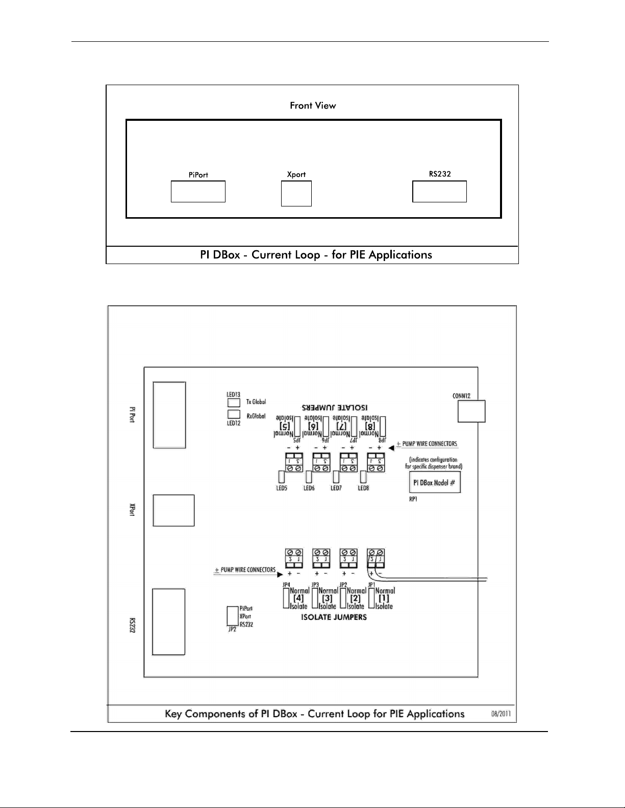
Current Loop Style PI DBoxes are used with Gilbarco and Wayne dispensers. Note dispenser-specific
instructions for use with each dispenser. For overview, see Diagram: PI DBox — Current Loop Style
on following page.
Follow instructions in the installation section of the accompanying product manual before connecting
PI DBox as follows:
1. Connect PI DBox to dispenser. Dispensers using current loop communication have two wires,
a negative and a positive, for connectivity. Locate the pair from each dispenser to be
connected and bring the pair into the PI DBox. The wires must be connected + to + and - to
- on unused wiring position(s) in the DBox. Ensure that positive and negative wires are not
crisscrossed at the PI DBox, as this will prevent communication with the controlling device.
Note: A recent DBox board redesign has eliminated the need to set Isolate Jumpers. For Current
Loop Style DBoxes with an Assembly Number of 900-11-6413, proceed to Step 3 in this section. If
installing a PI DBox with an Assembly Number of 900-11-6313, follow instructions in Step 2.
2. Note that isolation jumpers are present above wiring positions in the PI DBox. These jumpers,
marked JP1-JP8, should be left in isolate position until the controlling devices are connected
to the DBox. After connecting all dispensers to be used, move jumpers to normal for each
position connected.
Note: Steps 3-5 in the Current-Loop Style installation procedure are dependent upon the type of
application — PIE application or stand-alone application. Give careful attention to which steps are
needed for your particular application. Also, refer to the appropriate drawings for jumper settings,
interface connections and dispenser wiring.
Version 5.0 January 2012
Page 3
Page 8

PI DBox Installation Guide
For applications using PIE products:
For stand-alone applications, see description later in this section.
3. Set the jumper (JP2 position) to the desired interface type. The PiPort interface is used by
Progressive’s PIcon console. The RS232 and X Port interfaces are used by the FuelDirect Fuel
Control Solution.
4. Referring to the diagram of the front panel which follows, connect the PIcon to the PiPort
connector or connect the FuelDirect to the RS232 connector. If using ethernet connectivity,
connect to the X Port. Refer to the IP Addressing section at the end of this manual for further
ethernet instructions.
5. Proceed with programming of system.
Version 5.0 January 2012
Page 4
Page 9
PI DBox Installation Guide
Version 5.0 January 2012
Page 5
Page 10
PI DBox Installation Guide
For stand-alone applications:
For applications using PIE products, see description earlier in this section.
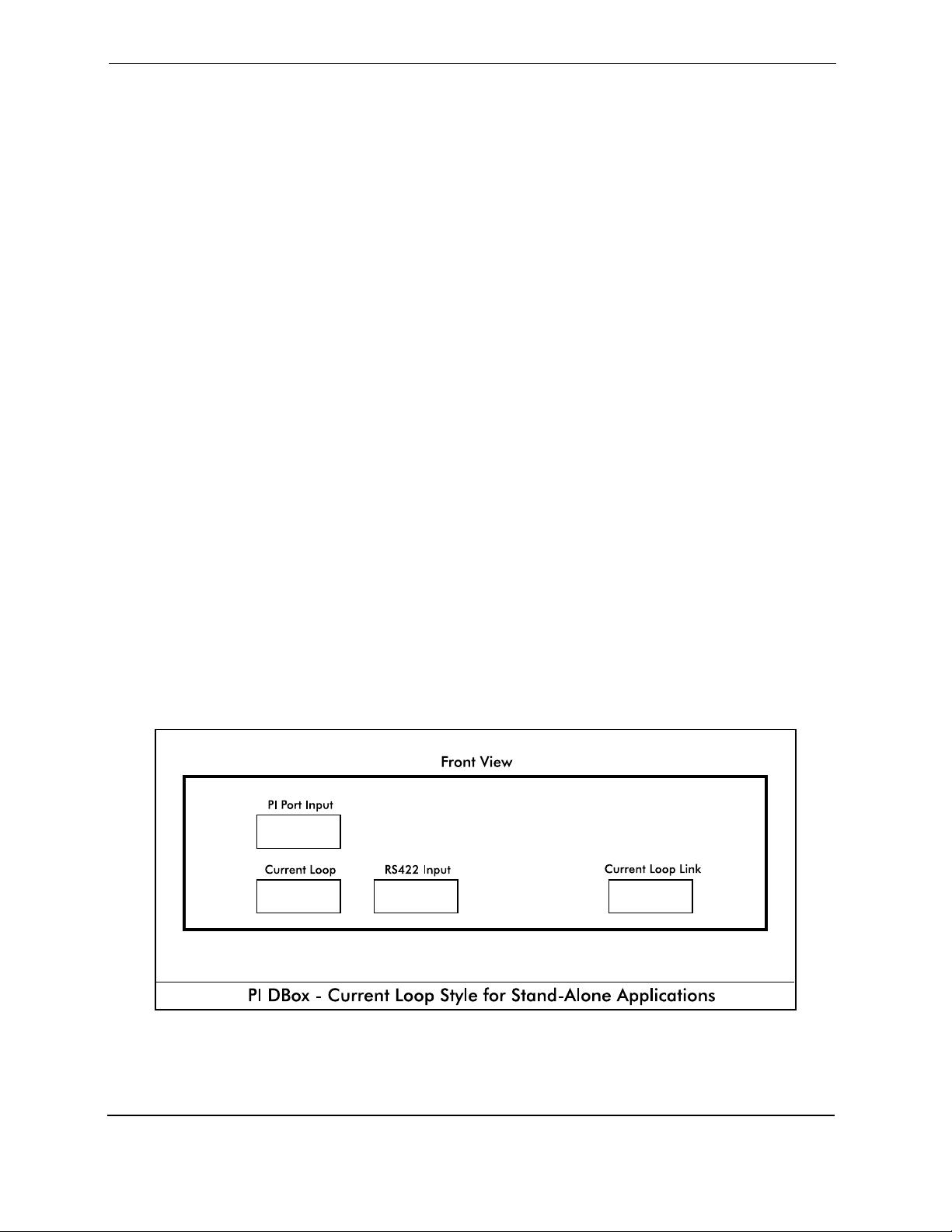
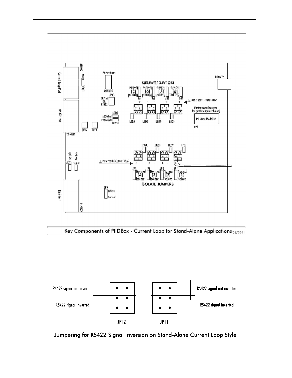
3. Referring to Diagram: Key Components of PI DBox — Stand-Alone Current Loop Style,
connect to the dispenser manufacturer’s controller. From the PI DBox, use the dispenser
manufacturer’s standard link. Wayne must be connected using current loop. The Gilbarco
controller can be connected using either current loop (two-wire interface) or RS422. Ensure
that position JP10 is jumpered to correspond to the connection used (CL for current loop and
RS422 for RS422 interface).
If connecting through RS422, in addition to selecting RS422 on jumper JP10, jumper
selections on positions JP11 and JP12 should be configured to either invert or not to invert
the RS422 signal. To invert RS422 signal, jumper the 4 pins closest to labeling of the
position. To choose not to invert the RS422 signal, jumper the 4 pins farthest from the
labeling of the position. See Jumpering for RS422 Signal Inversion for Stand-Alone Current
Loop Style which follows.
4. If linking dispensers, link through the Link Port of the PI DBox to the next PI DBox. There is a
normal/isolate switch associated with each link. Position JP9 should be jumpered to isolate if
not linking to a second DBox. JP9 should be jumpered to normal for two DBoxes. See
Diagram: Key Components of PI DBox — Stand-Alone Current Loop Style.
5. Proceed with programming of system.
Version 5.0 January 2012
Page 6
Page 11
PI DBox Installation Guide
Version 5.0 January 2012
Page 7
Page 12

PI DBox Installation Guide
PI DBox — Model Specific Installation
EZwire Style — EZ-DBox
Note all warnings in System Installation Warnings section.
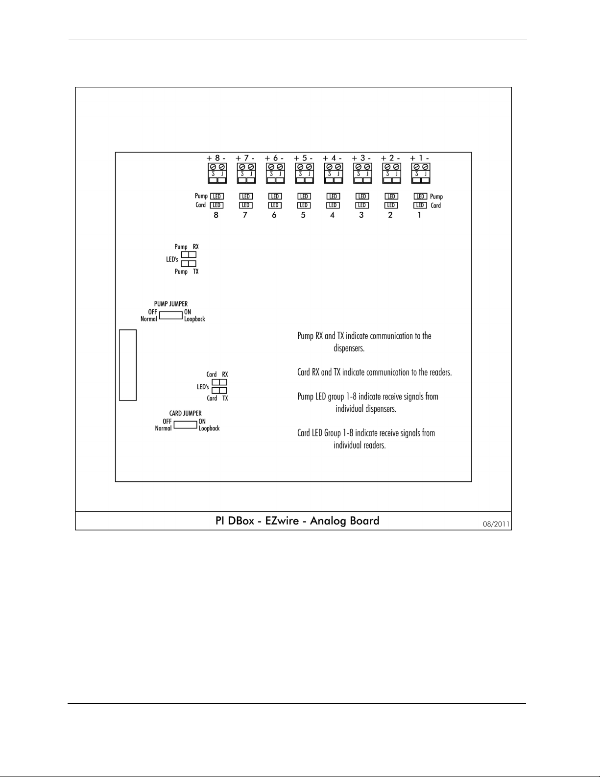
EZwire Style PI DBoxes are used with Gilbarco electronic dispensers with readers. Note
dispenser-specific instructions for use with each dispenser. For overview, see Diagram: PI
DBox — EZwire Style following these installation instructions.
Follow instructions in the installation section of the accompanying product manual before
connecting PI DBox as follows:
1. Connect PI EZwire DBox to the single pair of wires connected to each dispenser.
Referring to Diagram: PI DBox – EZwire – Analog Board, locate the pair of wires for
each dispenser and bring them into the EZwire DBox. Wires are connected + to +
and - to - on an unused position in the PI EZwire DBox. Ensure that the Positive and
Negative wires are not crisscrossed, as this will cause communication problems.
2. The PI EZwire DBox has no Isolation/Normal jumpers. This DBox will automatically
isolate a circuit that has an open loop.
Note: The next steps in the EZwire Style installation procedure are dependent upon the type of
application — PIE application or other. Give careful attention to which steps are needed for your
particular application. Also, refer to the appropriate drawings for jumper settings, interface
connections and dispenser wiring.
For applications using PIE ethernet connections (i.e., FuelDirect):
For non-PIE applications, see description later in this section.
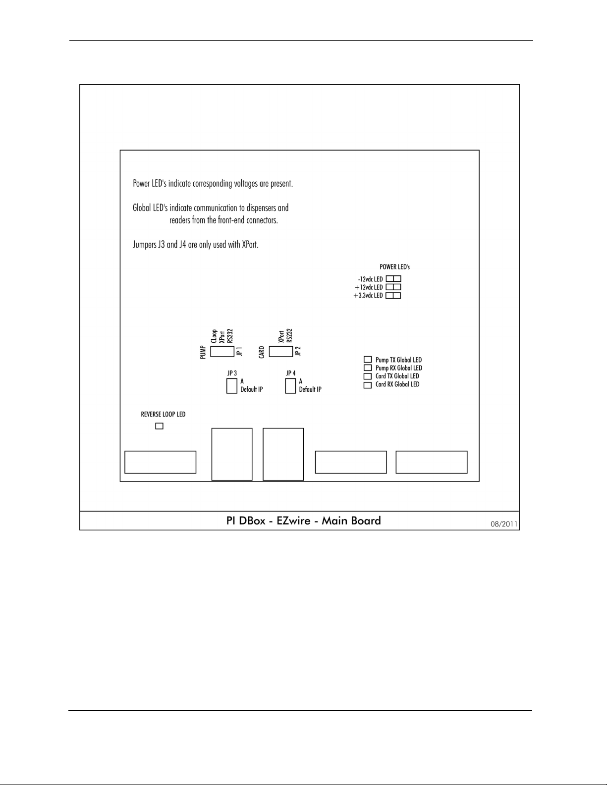
3. On the main board, set jumpers JP1 and JP2 to the XPort setting or RS232. See
Diagram: PI DBox – EZwire – Main Board
4. Referring to Diagram: PI DBox – EZwire – Front Panel, which follows, connect the
computer with the FuelDirect software to either the XPort for the ethernet or to the
RS232 port for RS232.
5. Proceed with programming the system.
Version 5.0 January 2012
Page 8
Page 13

PI DBox Installation Guide
For non-PIE applications, determine the type of connection required (i.e., Current Loop or RS232):
For PIE applications, see description above.
3. Set dispenser jumper JP1 to either the Current Loop (CL) or RS232 setting. Set reader
Jumper, JP2 to RS232.
4. Referring to the diagram of the front panel which follows, connect the
dispenser/reader controller to either the Current Loop or RS232 for dispensers and to
RS232 for readers.
5. Determine whether the application requires loop back when using the RS232
connections. Set H3 and H4 to the appropriate positions (LB= loop back).
6. Proceed with programming the system.
Version 5.0 January 2012
Page 9
Page 14
PI DBox Installation Guide
Version 5.0 January 2012
Page 10
Page 15
PI DBox Installation Guide
Version 5.0 January 2012
Page 11
Page 16

PI DBox Installation Guide
PI DBox — Model Specific Installation
Tokheim Style — Tok-DBox
Note all warnings in System Installation Warnings section.
Tokheim Style PI DBoxes are used with Tokheim dispensers. Note dispenser-specific instructions for
use with each dispenser. For overview, see Diagram: PI DBox — Tokheim Style on following page.
Follow instructions in the installation section of the accompanying product manual before connecting
PI DBox as follows:
1. Connect PI DBox to dispenser. Tokheim dispensers have three wires for connectivity: TTD,
TTC, and DCC. For each Tokheim dispenser being connected, bring dispenser wires into the
PI DBox and connect to TTD, TTC and DCC on an unused wiring position. Ensure that wires
are not crisscrossed at the DBox, as this will prevent communication with the controlling
device.
Note: A recent DBox board redesign has eliminated the need to set Isolate Jumpers. For Tokheim
DBoxes with an Assembly Number of 900-11-6412, proceed to Step 3 in this section. If installing a PI
DBox with an Assembly Number of 900-11-6312, follow instructions in Step 2.
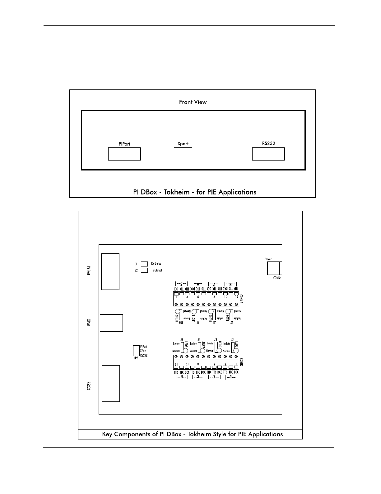
2. Note that above each wiring position in the PI DBox, an isolation jumper is present (positions
J2-J5 and J7-J10). Leave these jumpers in isolate position until the controlling devices are
connected to the DBox. After connecting all dispensers to be used, move jumpers to normal
for each position connected. Refer to Diagram: Key Components of PI DBox — Tokheim
Style.
Note: Steps 3-5 in the Tokheim -Style installation procedure are dependent upon the type of
application — PIE application or stand-alone application. Give careful attention to which steps are
needed for your particular application. Also, refer to the appropriate drawings for jumper settings,
interface connections and dispenser wiring.
For applications using PIE products:
For stand-alone applications, see description later in this section.
3. Set the jumper on JP2 to the interface type to be used. The PiPort interface is used by the
PIcon Console. The RS232 and Xport are used by the FuelDirect Fuel Control Solution.
Version 5.0 January 2012
Page 12
Page 17
PI DBox Installation Guide
4. Connect the PIE controller or console to the connector shown on the following diagram. If
using ethernet connectivity, refer to the IP Addressing section at the end of this manual.
5. Proceed with programming of the system.
Version 5.0 January 2012
Page 13
Page 18
PI DBox Installation Guide
For stand-alone applications:
For applications using PIE products, see description earlier in this section.
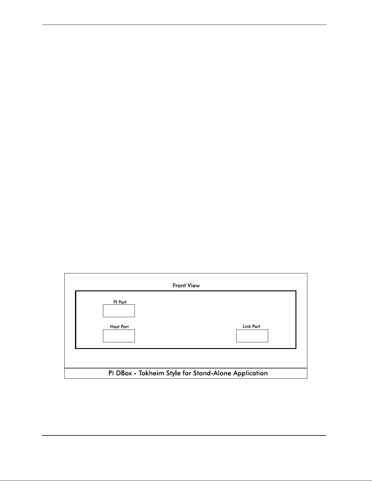
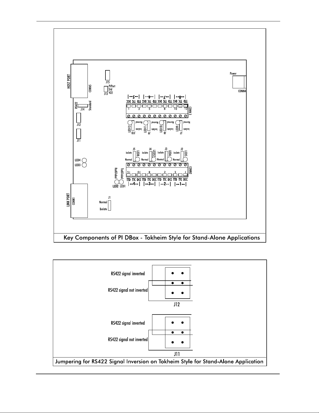
3. Referring to Diagram: Key Components of PI DBox — Tokheim Style for Stand-Alone
Application, connect using the Tokheim standard proprietary interface of Tokheim RS422
interface. Jumpers J13 and J14 must be configured to correspond to the interface selections
(Std for standard or 422 for RS422).
If connecting through RS422, in addition to selecting RS422 on jumper JP13, jumper
selections on positions JP11 and JP12 should be configured to either invert or not to invert
the RS422 signal. To invert RS422 signal, jumper the 4 pins farthest from labeling of the
position. To choose not to invert the RS422 signal, jumper the 4 pins closest to the labeling
of the position. See Diagram: Jumpering for RS422 Signal Inversion on Tokheim Style for
Stand-Alone Application which follows.
4. If linking dispensers, link through the Link Port of the PI DBox to the next PI DBox. There is a
normal/isolate switch associated with each link. Position JP9 should be jumpered to isolate if
not linking to a second DBox. JP9 should be jumpered to normal for two DBoxes. See
Diagram: Key Components of PI DBox — Tokheim Style for Stand-Alone Applications.
5. Proceed with programming of system.
Version 5.0 January 2012
Page 14
Page 19
PI DBox Installation Guide
Version 5.0 January 2012
Page 15
Page 20

PI DBox Installation Guide
PI DBox — Model Specific Installation
RS485 Style — RS485 DBox
Note all warnings in System Installation Warnings section.
RS485 Style PI DBoxes are used with Wayne CAT card reader, Tokheim DPT, Tatsuno dispenser, and
Nuovo Pignone dispenser. Note dispenser-specific instructions for use with each dispenser. For
overview, see RS485 diagrams on following page.
Follow instructions in the installation section of the accompanying product manual before connecting
PI DBox as follows:
1. Connect PI DBox to dispenser. Dispensers using RS485 communication have three wires for
connectivity: +, -, and ground. For each RS485 dispenser being connected, bring dispenser
wires into the PI DBox and connect to +, -, and ground on an unused wiring position. Ensure
that wires are not crisscrossed at the DBox, as this will prevent communication with the
controlling device. Connect no more than four physical devices in each of the four groups of
connections (1-4, 5-8, 9-12, and 13-16). Two device addresses are equivalent to two
connections.
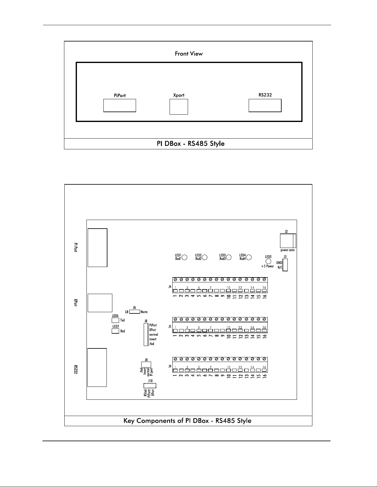
2. To connect to a PIE console over the PI DBox’s PiPort proprietary link, use PIE’s 9000 15
0034 cable. Jumper J6 must be set for LB. Jumpers J8 and J10 must both be jumpered for
PiPort. Jumper J3 should be set to GND. If connecting to PIE’s FuelDirect Fuel Control
Solution using the RS232 port, set J8 to /txd and J10 to RSTxd. If connecting to FuelDirect
using ethernet, set J8 and J10 to XPort. (Refer to IP Addressing section at end of this manual
for further instruction on ethernet connectivity.)
3. Proceed with programming of system.
Version 5.0 January 2012
Page 16
Page 21
PI DBox Installation Guide
Version 5.0 January 2012
Page 17
Page 22

PI DBox Installation Guide
PI DBox — Model Specific Installation
Kraus Electronic Style — KB DBox
Note all warnings in System Installation Warnings section.
KB DBoxes are used with either Kraus or Bennett Electronic Dispensers. Brand selection is made by
simply configuring jumper JP5 to either Kraus or Bennett. Although the same DBox is used in both
applications, in this document we refer to either “Kraus Electronic Style” or Bennett Electronic Style” for
instruction purposes. Note dispenser-specific instructions for use with each dispenser. For overview of
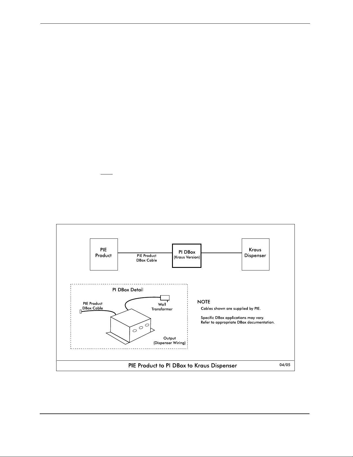
Kraus application see Diagram: Key Components of PI DBox — Kraus/Bennett Style for Kraus
Application following this section.
The following Kraus models must have the minimum version of software noted to work properly with
Progressive equipment:
Micon 100
152 printed circuit board versions 3.1 & 3.2
252 printed circuit board version 6.30
463 PLCC processor version 7.03
Micon 200 version 1.09
Micon 300 version 2.04
Micon 500 all versions
Follow instructions in the installation section of the accompanying product manual before connecting
PI DBox as follows:
1. Disconnect the Kraus console (if applicable) and connect the Kraus style PI DBox to the PIE
product, using the appropriate cable supplied by PIE. Refer to Diagram: PIE Product to PI
DBox to Kraus Dispenser which follows.
2. Connect the data communication wires from the Kraus dispenser into the dispenser
connectors on the Kraus Style PI DBox. See Diagram: PIE Product to PI DBox to Kraus
Electronic Dispensers and Diagram: Key Components of PI DBox — Kraus/Bennett Style for
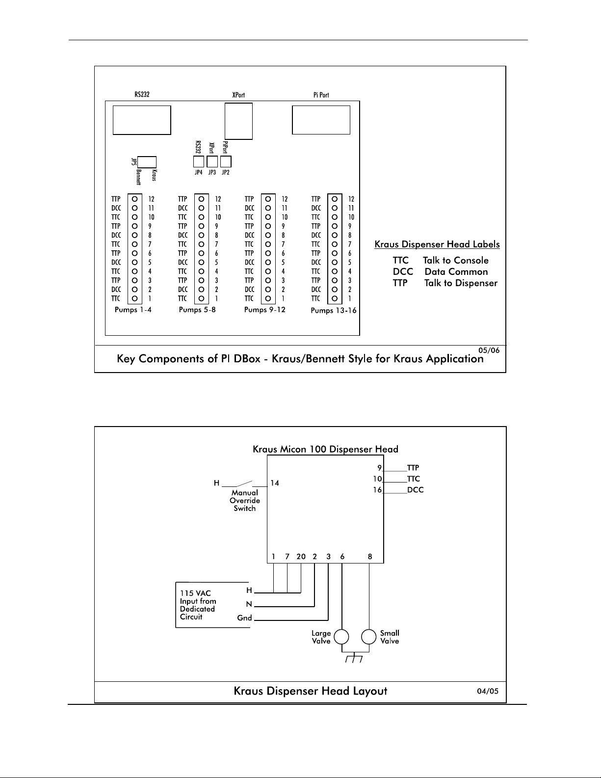
Kraus Application. Also note the layout of the Kraus dispenser head, referring to Diagram:
Kraus Dispenser Head Layout. There are three data communication wires connecting to a
Kraus dispenser. They are labeled as follows:
TTC Talk to Console/Kraus dispenser transmit data
TTP Talk to Dispenser/Kraus dispenser receive data
DDC Data Common / Kraus dispenser ground
Version 5.0 January 2012
Page 18
Page 23
PI DBox Installation Guide
3. Referring to Diagram: Key Components of PI DBox — Kraus/Bennett Style for Kraus
Application, configure jumpers. At position JP5, set the jumper to Kraus. Locate jumpers
JP4, JP3, and JP2. Jumper the appropriate position for the type of interface to be used:
RS232 interface — jumper only position JP4
Ethernet (XPort) interface — jumper only position JP3
PIE product (PiPort) interface — jumper only position JP2
4. Proceed with programming of the system.
Note: For MTI (D&H) computer heads, the TTC and TTP signals must be jumpered to the second
address (i.e., 1 to 2, 3 to 4, 5 to 6, . . . . 15 to 16). Refer to the board orientation for the dispenser
position.
The MTI (D&H) heads must be upgraded to the latest hardware version for the communication to
operate properly. Please contact MTI (Measurement Technology, Inc.) for upgrades.
Version 5.0 January 2012
Page 19
Page 24
PI DBox Installation Guide
Version 5.0 January 2012
Page 20
Page 25

PI DBox Installation Guide
PI DBox — Model Specific Installation
Bennett Electronic Style — KB DBox
Note all warnings in System Installation Warnings section.
KB DBoxes are used with either Kraus or Bennett Electronic Dispensers. Brand selection is made by
simply configuring jumper JP5 to either Kraus or Bennett. Although the same DBox is used in both
applications, in this document we refer to either “Kraus Electronic Style” or Bennett Electronic Style” for
instruction purposes. Note dispenser-specific instructions for use with each dispenser. For overview of
Bennett application see Diagram: Key Components of PI DBox — Kraus/Bennett Style for Bennett
Application following this section.
Follow instructions in the installation section of the accompanying product manual before connecting
PI DBox as follows:
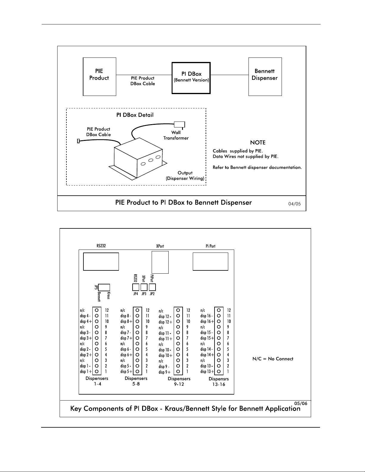
1. Disconnect the Bennett console (if applicable) and connect the Bennett Style PI DBox to the
PIE product, using the appropriate cable supplied by PIE. Refer to Diagram: PIE Product to PI
DBox to Bennett Dispenser following this section.
2. Connect the data communication wires from the Bennett dispenser(s) (Orange [+] and Yellow
[-]) into the dispenser connectors on the Bennett style PI DBox provided by PIE. See Diagram:
Key Components of PI DBox — Kraus/Bennett Style for Bennett Application at end of this
section for wiring.
3. Referring to Diagram: Key Components of PI DBox — Kraus/Bennett Style for Bennett
Application, configure jumpers. At position JP5, set the jumper to Bennett. Locate jumpers
JP4, JP3, and JP2. Jumper the appropriate position for the type of interface to be used:
RS232 interface — jumper only position JP4
Ethernet (XPort) interface — jumper only position JP3
PIE product (PiPort) interface — jumper only position JP2
4. Proceed with programming of the system.
Version 5.0 January 2012
Page 21
Page 26
PI DBox Installation Guide
Version 5.0 January 2012
Page 22
Page 27

PI DBox Installation Guide
PI DBox
Troubleshooting and Diagnostics
LED Indicators
When installing the PI DBox, refer to on-board LED indicators for troubleshooting assistance.
LED layout is illustrated for Current Loop Style, Tokheim Style and RS485 Style PI DBoxes in
Diagram: Key Components of PI DBox under the manual section for each of these specific
styles.
Additional Troubleshooting Steps for Unsuccessful Communications
C Run one dispsenser only by isolating all the rest at the site.
C Recheck wires at dispenser junction box, as well as in the PI DBox
C On PI DBox models with power supply, make sure power is applied.
C Make sure console or controller is plugged into the correct connector on the front of the PI
DBox.
C Ensure that all configuration jumpers or switches are set correctly for the application.
Version 5.0 January 2012
Page 23
Page 28
PI DBox Installation Guide
PI DBox
IP Addressing
The default IP address for the PI DBox is 192.168.0.200. When the IP jumper is installed, the default
address changes to 192.168.0.199. Since each device at the site must have a unique IP address, it
may be necessary to reconfigure all DBoxes to avoid conflicting addresses on the network. The IP
address for each PI DBox may be changed by following one of two procedures.
Changing IP Address
Using either of these methods to change the IP address of a PI DBox, the default IP jumper must be
installed and must remain installed throughout the entire procedure. Once the procedure is
completed, remove the jumper and reset the DBox.
Preferred Method: Run Device Installer
Install the IP jumper, power cycle the DBox and then run Lantronix Device Installer. (Lantronix
Device Installer is on the install disk supplied by Progressive International or may be found at
the Lantronix wed site lantronix.com.) Once the update is complete, remove the jumper and
reset the DBox.
Alternative Method: Run HyperTerm configure and set up a new connection using Winsock with
TCP protocol
Install the IP jumper and power cycle the DBox. Then run HyperTerm configure and set up a
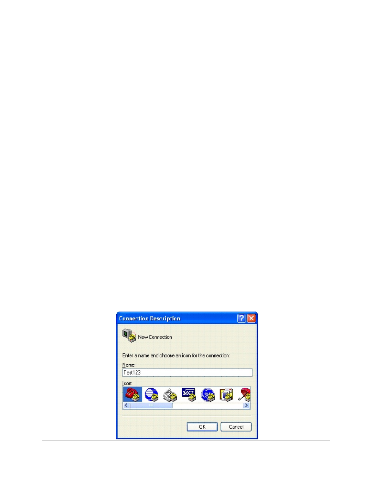
new connection using Winsock with TCP protocol. Under Name, select any name for the
session. Icon to appear onscreen may be changed under the Icon selection. Click on OK.
See Connection Description dialog box below.
Version 5.0 January 2012
Page 24
Page 29
PI DBox Installation Guide
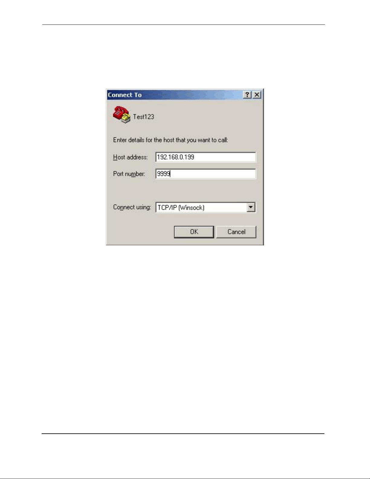
Set the Host Address to the DBox default of 192.168.0.200. Set the Port Number to 9999.
Under Connect Using, select TCP/IP (Winsock). Click on OK. See Connect To dialog box
below.
Version 5.0 January 2012
Page 25
Page 30
PI DBox Installation Guide
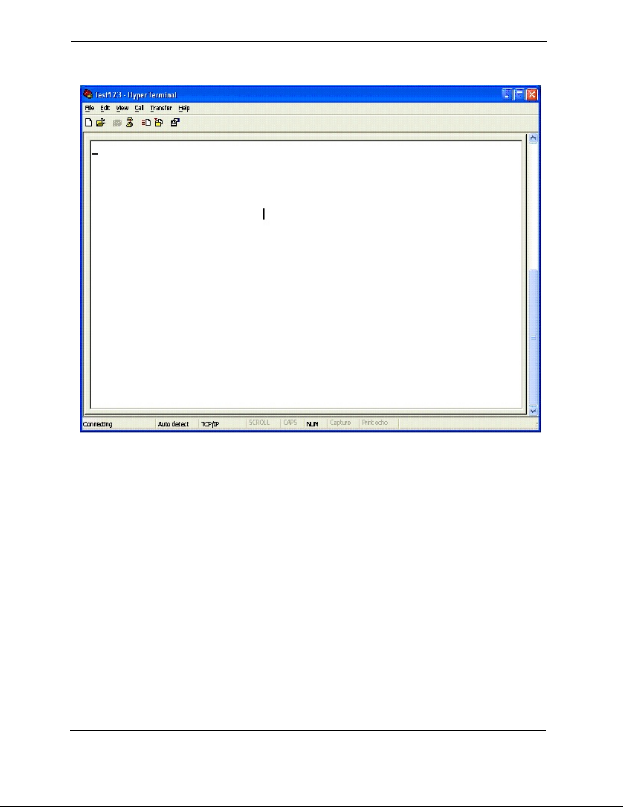
HyperTerm screen will appear as shown below.
Version 5.0 January 2012
Page 26
Page 31
PI DBox Installation Guide
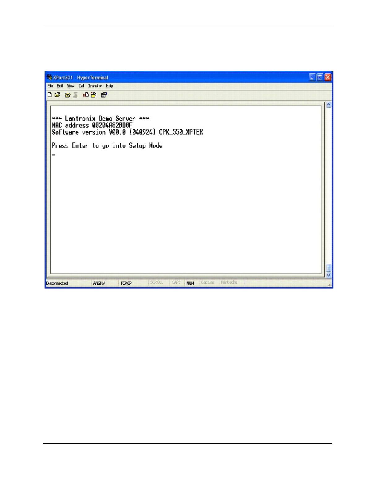
Make sure the DBox is connected to the network and apply power to the DBox. The following
message will appear on the Hyperterm session. (Note that your DBox mac address will be
different for each unit.)
Version 5.0 January 2012
Page 27
Page 32
PI DBox Installation Guide
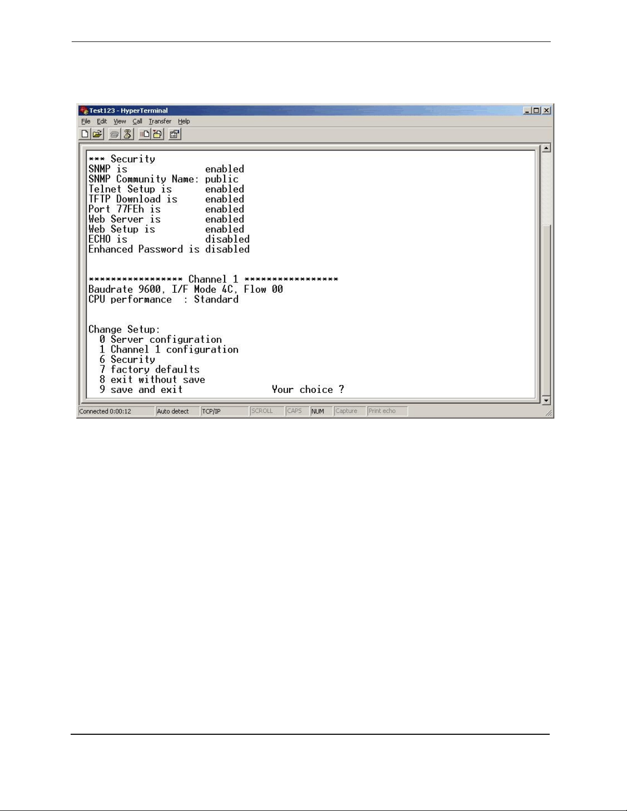
After pressing Enter, the following screen will appear.
Version 5.0 January 2012
Page 28
Page 33
PI DBox Installation Guide
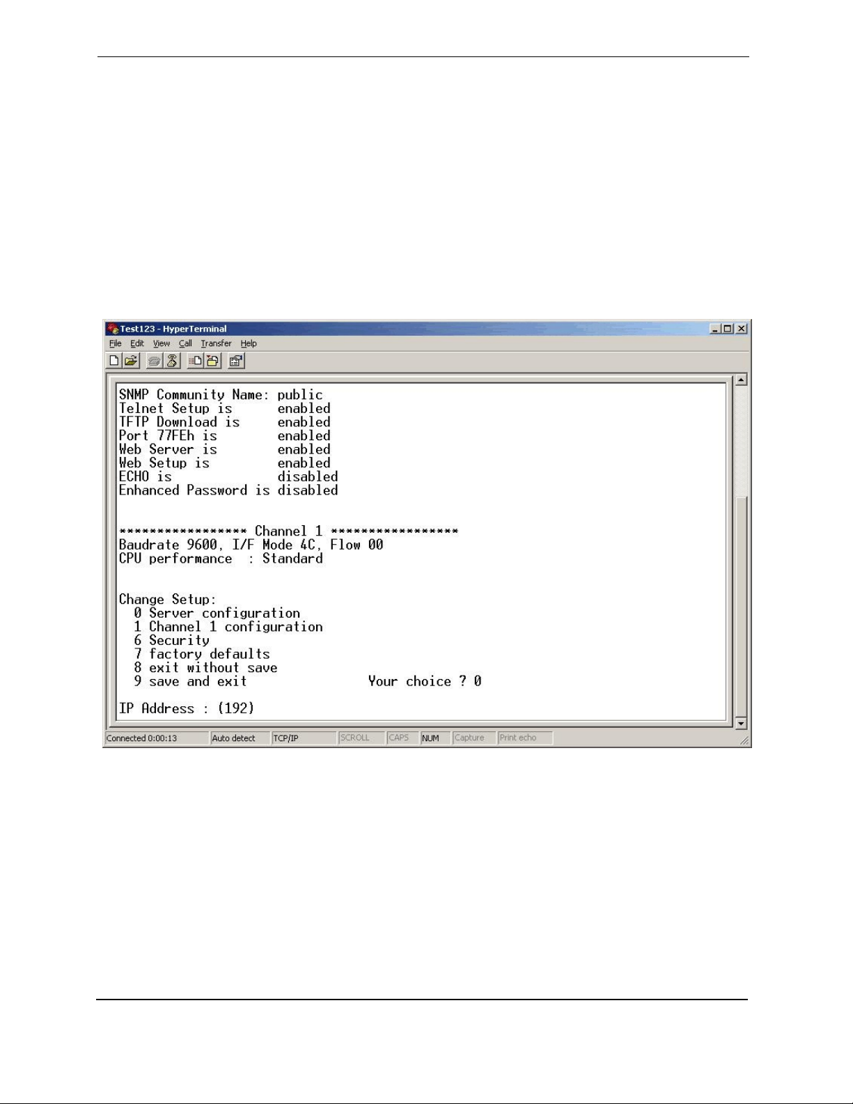
Select option 0 for Server Configuration and the following screen will appear. Assign new
numbers for the first field of the IP address and press Enter or leave unchanged and press
Enter to keep the first field the same. You will be prompted to assign new numbers for the
second field or to accept the default numbers by pressing Enter. This process continues for
each of the four fields. Only one number in one field must be changed to make the IP
address unique — or each of the fields may be changed if it provides a more systematic setup
for the programmer. (Use caution that numbers do not fall outside the range of the SUBNET
MASK.)
Press Enter for all other options.
Version 5.0 January 2012
Page 29
Page 34
PI DBox Installation Guide
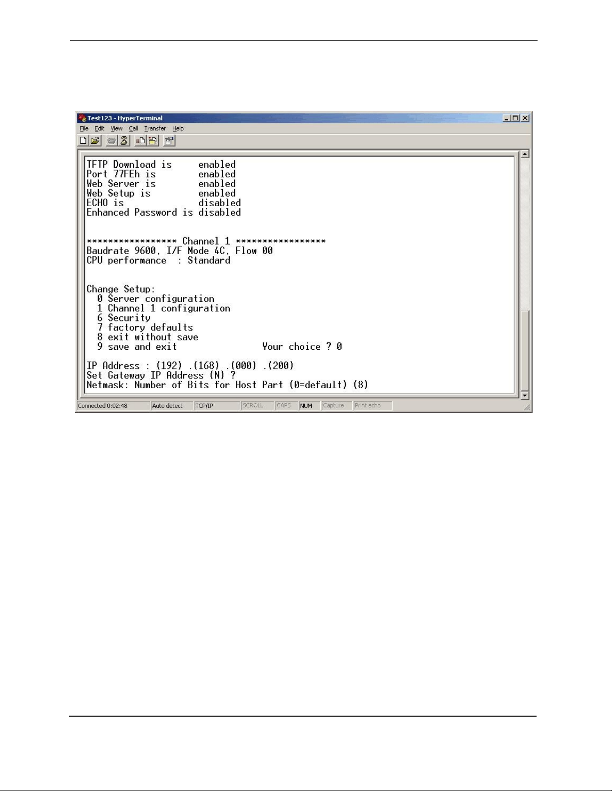
The following screen will appear, showing the changed IP address.
Version 5.0 January 2012
Page 30
Page 35
PI DBox Installation Guide
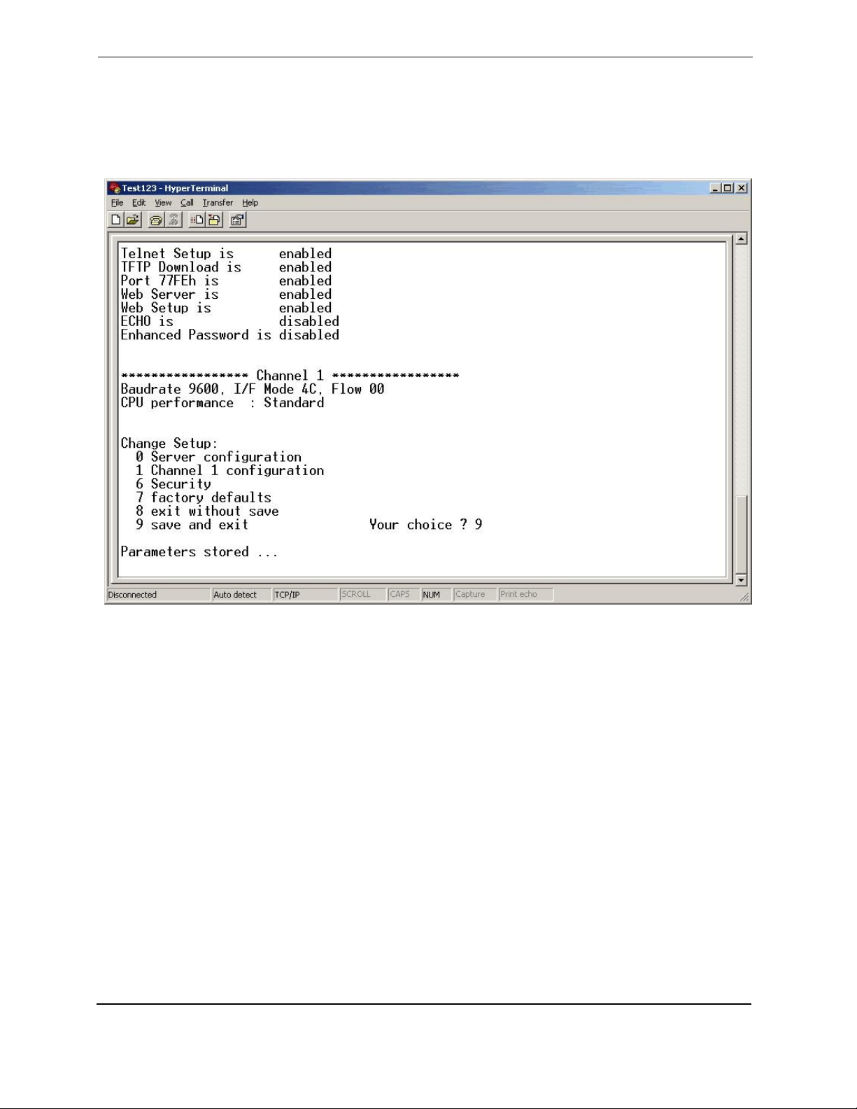
Double check under the basic parameters listing to make sure your new IP address is correct.
If correct, select option 9 to save and exit. If changes need to be made, select option 0 to
reenter the server configuration mode.
Remove the IP jumper and reset the DBox. At this point the PI DBox is reconfigured and ready to
connect to the system network for site installation and testing.
Version 5.0 January 2012
Page 31
 Loading...