

Page 1

C2000
console CONTROLLER
User Reference Manual
and
Installation Guide
Page 2
2422 Atlantic Avenue
Raleigh, North Carolina 27604
Phone 919 821-1323 • Fax 919 821-1325
www.pie-corp.com
© Copyright 2001
Progressive International Electronics
Page 3
C2000
console CONTROLLER
User Reference Manual
and
Installation Guide
© Copyright 2001
Progressive International Electronics
2422 Atlantic Avenue
Raleigh, North Carolina 27604
Phone 919 821-1323 • Fax 919 821-1325
www.pie-corp.com
Page 4

Copyright © 2001 Progressive International Electronics, Inc.
All rights reserved. No part of this publication may be reproduced, stored in a
retrieval system or transmitted, in any form or by any means, electronic,
mechanical, photocopying, recording, or otherwise, without the prior written
permission of Progressive International Electronics, Inc.
Printed in U.S.A.
Page 5

C2000
CONTENTS
GENERAL INFORMATION & WARRANTY .............. 1
General Information ........................ 1
C2000 Manufacturer's Warranty ................ 3
OPERATION ................................... 5
Introduction .............................. 5
Display and Status Indicators .................. 7
Sales ................................... 9
Select Functions .......................... 11
PROGRAM & REPORT ........................... 14
Introduction ............................. 14
PIN Code Access .......................... 15
Manager Access ..................... 15
Operator Access ..................... 16
Mode Descriptions ........................ 17
Mode 1 — Pump Setup Information ....... 17
Mode 2 — Product Information .......... 18
Mode 3 — Beeper Settings ............. 20
Mode 4 — Clock/Calendar............. 21
Mode 5 — Serial Port ................. 21
Mode 6 — Peripheral Devices ........... 23
Mode 7 — Print Header ............... 24
Mode 10 — Read Reports .............. 26
Mode 11 — Print Reports .............. 27
Mode 12 — Clear Resettable Totals ....... 28
Mode 97 — Program Operator PIN Code . . 28
Mode 98 — Program Manager PIN Code . . . 29
Mode 99 — Console Diagnostics......... 29
i
Page 6

INSTALLATION ................................ 30
Introduction ............................. 30
General Installation Guidelines ............... 31
Installation Warnings ....................... 32
Gilbarco Electronic Fuel Pumps ............... 33
Tokheim Electronic Fuel Pumps................ 36
Kraus Micon 100 Electronic Fuel Pumps ......... 39
Wayne/Dresser Electronic Fuel Pumps ........... 43
Bennett Electronic Fuel Pumps ................ 45
ii
Page 7
C2000
GENERAL INFORMATION & WARRANTY
General Information & Warranty
General Information
The C2000 is an economical, full-featured console designed to
provide control of up to 16 fueling positions. While most consoles
can only control one type of fuel dispenser, the C2000 may be
configured to run all major brand electronic and mechanical
dispensers. This is accomplished through the use of configurator
boxes that contain the unique circuitry required to interface to each
individual dispenser.
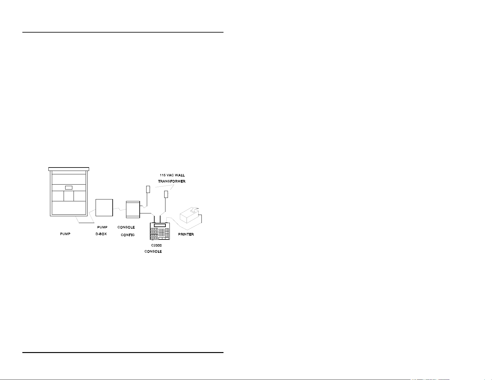
Figure 1: C2000 Installation
Your C2000 provides full features, yet is very simple to install and
operate. Due to meticulous design of the keyboard and display
layout, keystrokes are kept to a minimum during programming
setup and normal operation modes.
‚ 1
Page 8

C2000
Standard features provided by the C2000 for efficient control of
your fueling dispensers include:
CFull featured console which includes prepay/postpay, preset,
drive-away alerts, stacked sale, cash/credit operation.
CManagement features including dispenser, shift and station
totals, management security, prices programmed by product.
CEasy to read LCD display.
CRegister style keyswitch for efficient operator entry.
CControls up to 16 fueling positions — including
electronic dispensers
CAudible alerts for call, drive-away and collect.
CBattery backed memory to retain data in the event of power
outage.
CBuilt-in hardware clock to time stamp all reports.
CCompact size allowing convenient counter-top positioning
while utilizing a minimum amount of valuable counter space
— or may be bracket mounted.
CStandard printer interface for use with most low-cost printers.
CEase of installation — console wires directly into dispenser
distribution boxes.
General Information & Warranty
all major
and new blending pumps.
Prior to installation or operation of the C2000, please review each
section of this manual to familiarize yourself with the system.
‚ 2
Page 9

C2000
General Information & Warranty
C2000 Manufacturer's Warranty
Progressive International Electronics, Inc. (SELLER) warrants to the Purchaser of the
C2000 fuel control equipment manufactured by Seller against defects in material or
workmanship for one (1) year from date of shipment. Seller will replace or repair
defective parts or replace and issue credits to the Purchaser's account in accordance with
the following Conditions of Warranty.
CONDITIONS OF WARRANTY
1. Credit will be applied only when the completed warranty request form and the
defective parts are received and inspected.
Decisions to repair or replace defective equipment are solely at
the discretion or PIE.
2. When parts shipments are made prior to receiving the required warranty request and
defective parts, they will be billed to the Purchaser.
3. In all cases, approved warranty requests will be expedited by issuing the appropriate
credit to the Purchaser's account and shipping replacement parts.
4. Credits will not be issued for parts and no cash refunds for warranty credits will be
made.
5. All components and parts must be returned to the factory prepaid, and in turn,
replacement components and parts will be returned prepaid by the factory.
6. Seller's warranty applies only if the equipment has been installed and used in
accordance with Seller's instructions. The warranty is void if any unauthorized
alteration or addition has been made to the equipment or if it has been subject to
damage caused by abuse, misapplication, accident or improper operation.
7. The Seller's liability for any damages, including contribution and indemnification,
arising out of or in any way connected with the supplying of the equipment or its
use, shall not in any case exceed the cost of repair of the equipment as herein
provided. Upon expiration of the warranty, all such liability, as well as any other
liability, shall terminate.
8. Nothing contained herein shall make the Purchaser, its agents or employees, an agent
or representative of Seller and Seller assumes no responsibility of any act, omission,
representation or warranty by the Purchaser or anyone else except as expressly stated
herein.
9. The final Decision as to the validity of any claims arising under the warranty shall be
determined solely by the Seller.
‚ 3
Page 10

C2000
THE FOREGOING WARRANTY IS IN LIEU OF ALL OTHER WARRANTIES,
EXPRESSED OR IMPLIED, INCLUDING, BUT NOT LIMITED TO, THE IMPLIED
WARRANTIES OR MERCHANTABILITY AND FITNESS FOR A PARTICULAR
PURPOSE WHICH EXCEED THE AFORESAID OBLIGATIONS AND ARE
HEREBY DISCLAIMED AND EXCLUDED BY SELLER.
Warning: Installation must comply with the National Electrical Code, as well as
Federal, State, Local and all applicable codes.
Warning: High voltages are present in this equipment. Disconnect all power before
making installation to prevent personal injury or equipment damage.
Warning: Do not install C2000 units in a volatile, combustible or explosive atmosphere.
All C2000 units must be protected from severe vibration, extreme temperatures and
excessive humidity.
Any peripheral equipment is to be installed over a non-hazardous location.
Any peripheral equipment connected to the C2000 must be UL listed and using standard
RS232 or RS485 communication.
The C2000 must be plugged into a dedicated 115 VAC wall socket with bonded earth
ground.
General Information & Warranty
W A R N I N G
‚ 4
Page 11
C2000
OPERATION
Operation
Introduction
In this section, all functions available to the cashier for operation
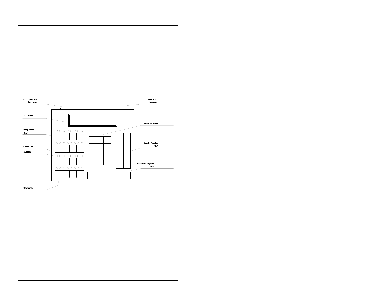
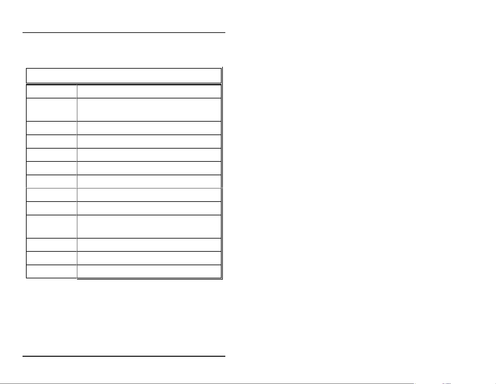
of the C2000 are outlined. Table 1 on the following page provides
brief descriptions of key functions. Also, refer to Figure 2 below
for general locations of various keys, indicators and display.
Figure 2: C2000 Keyboard Layout
There are two types of operations for the cashier:
! Pump control
pump select key, followed by the keys corresponding to the
command for the C2000 to make upon that pump.
! Select functions
time and date, and console deactivation functions.
— initiated by pressing the appropriate
— provide the cashier access to the shift,
‚ 5
Page 12
C2000
Operation
Active Keys
PUMP KEYS Select pump number
AUTHORIZE Authorize selected pump or resume a stopped
pump
CASH PAID Pay out the sale in cash
CREDIT PAID Pay out the sale in credit
VOLUME Display the volume of the sale
PPG Display the price per gallon of sale
A/B Toggle between the A & B sales
PUMP STOP Stop an authorized pump
PRINT Print a receipt
CHANGE Show the change of a preset or prepay sale;
also show the preset amount
GRADE Set the grade for an authorization
MANAGER Enter/exit program & report modes
SELECT Refer to Operation Section, Special Functions
Table 1: Key Functions
‚ 6
Page 13
C2000
Operation
Display and Status Indicators
The LCD display provides the cashier with all sale information for
the pump selected. It also provides data such as time/date and shift
totals reports when using the select functions. Listed below in
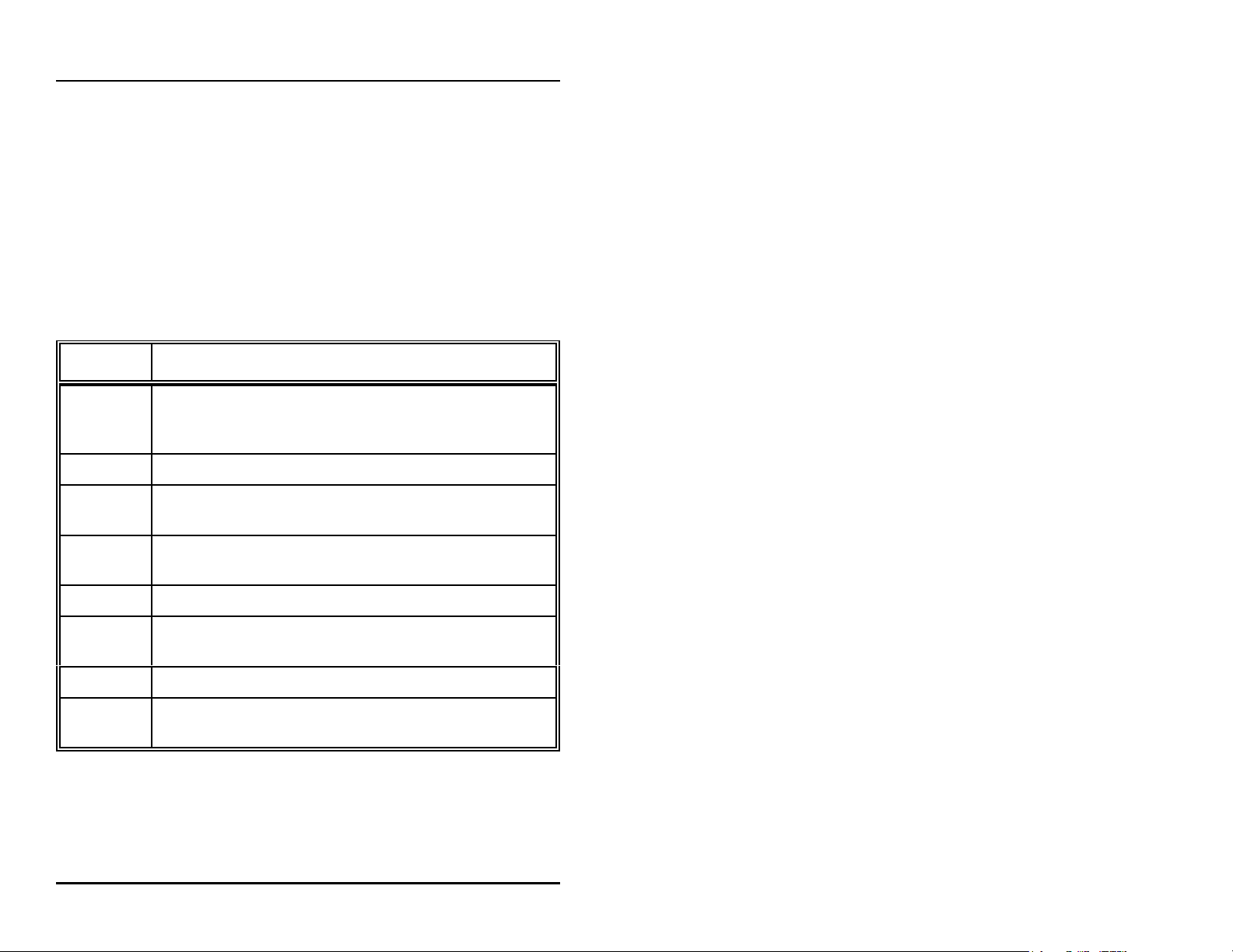
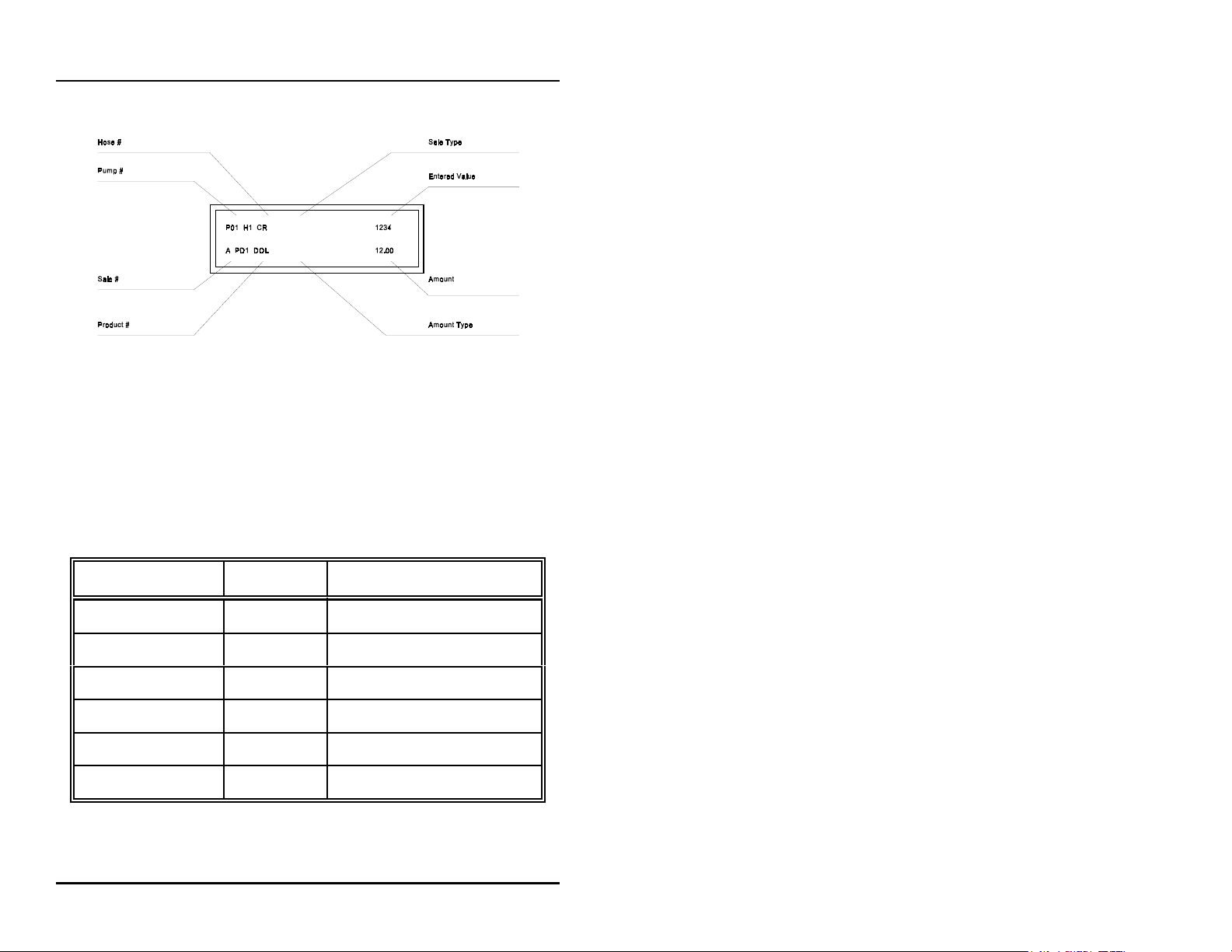
Table 2 are the various fields of data which may appear in the
display area, along with a brief description of each field.
Display Description
Indicates the current/active pump #/fueling position.
Pump # Further key entry, such as authorization or payment will
apply to the current pump #.
Hose # Indicates the active hose at a fueling position.
Sale Type
Sale #
Product # Indicates the product type for the displayed sale.
Amount Indicates type of data being displayed in the amount field.
Type
Amount Indicates the value, dollar or volume of the active sale.
Entered Displays any data entered on the numeric keypad.
Value
Indicates the method of payment selected for a sale —
cash (CA) or credit (CR).
Indicates which sale is selected — A or B (current sale or
stacked sale).
Table 2: Display Data
‚ 7
Page 14
C2000
Operation
Figure 3: Display Layout
The LEDs above each of the pump select keys are the
status
indicators for that particular pump/fueling position. The green
LED on the left indicates
indicates
collect/stopped
call/in use
. The red LED on the right
. Table 3, below, shows the various states
these LEDs represent for each pump/fueling position.
GREEN LED RED LED STATUS
Fast Flash — Call for service
On Solid — Authorized
— Slow Flash Collect "A" Sale
— On Solid Pump Stopped
Fast Flash and Fast Flash Drive-Away
Slow Flash and Slow Flash Collect "A" and "B" Sales
Table 3: LED Indicators for Pump/Fueling Positions
‚ 8
Page 15
C2000
Operation
Sales
Authorization must be made for a sale as either a
Postpay,
or
Prepay
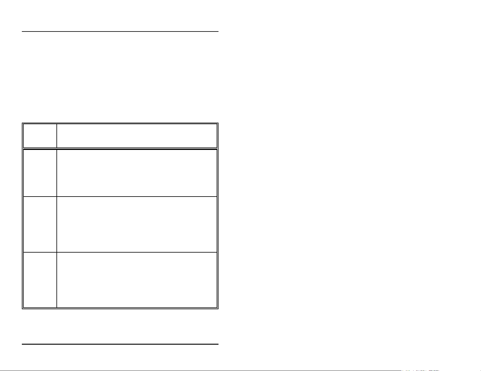
sale. Table 4, below, describes the sequence
Postpay, Preset
for completing each type of authorized sale.
NOTE: An actual key action is indicated by
Sale
Type
To authorize a pump for a Postpay/Fillup operation, press
the appropriate <PUMP #> key and then press the red
Postpay <AUTHORIZE> key. To pay out the sale on the console,
press the <PUMP #> key. Press either <CASH> or
<CREDIT> key. To print a receipt, press <PRINT>
To authorize a pump for a preset amount, press the
appropriate <PUMP #> key and then enter the preset
Preset amount on the numeric keypad. Press the red
Postpay <AUTHORIZE> key. (Note that the amount entered on the
numeric keypad appears on the display in the ENTERED
VALUE field.)
Procedure
<____>
Prepay
To authorize a pump for a prepay sale, press the
appropriate <PUMP #> key; then enter the amount paid
on the numeric keypad. (Note that the amount entered on
the numeric keypad appears on the display in the ENTERED
VALUE field.) Press method of payment, <CASH> or
<CREDIT> key; then the red <AUTHORIZE> key.
Table 4: Sales Procedure by Authorization Type
‚ 9
Page 16

C2000
If the transaction is a stacked sale (A/B), it is important to select
the correct sale with the
<CASH>
—
indicators show the state of a transaction, such as
collect,
procedures.)
Should it become necessary to stop all of the dispensers due to an
emergency condition, press the large red button on the front edge
of the C2000. This will place all of the dispensers in a stopped
condition until the operator clears the emergency. This is
accomplished by selecting each dispenser with the
and then pressing the
etc. (Refer to the Quick Reference Guide for general sales
<CREDIT>
or
<A/B>
<AUTHORIZE>
key before the method of payment
key — is pressed. The status
key.
Operation
call for service,
<PUMP #>
key
‚ 10
Page 17
C2000
Operation
Select Functions
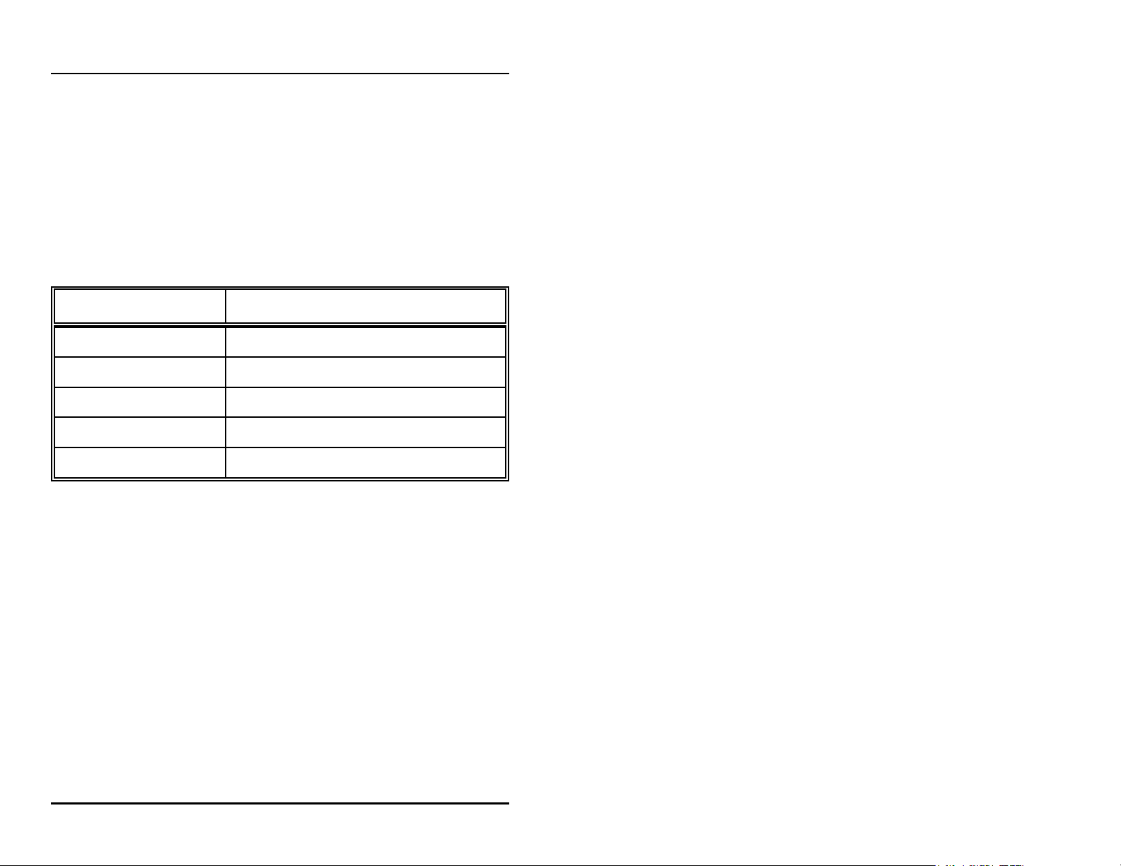
Listed below are the five special operator
select functions
, along
with the key sequences required to execute them. Each key
sequence begins with the operator pressing the
<SELECT>
key.
(Note that the display will prompt you to enter a function key for
the appropriate mode.)
Key Pressed Resulting Message
<ENTER>
<PRINT>
<CHANGE>
<SELECT>
<PUMP STOP>
For example, a typical sequence of select functions might be the
sequence used to determine shift totals. This select function would
be accomplished by first pressing the
Function
will appear in the display, prompting the operator to
enter the key for the desired function. Pressing the
will cause the display to begin showing the volume shift totals. To
view the cash shift totals, press the
credit shift totals may be viewed by pressing the
PAID>
press the
key. To display all of the product shift totals, continue to
<ENTER>
Show Shift Totals
Print Current Shift Totals
Shift Change
Show the Console Clock
Turn off the Console
Table 5: Select Key Functions
<CASH PAID>
key.
<SELECT>
key. The word
<ENTER>
key. The
<CREDIT
key
‚ 11
Page 18

C2000
This will scroll all of the shift totals. After exhibiting all of the
totals, the display will return to the select function entry screen. If
another select function is desired, it may be entered, or the select
function mode may be exited by pressing the
A similar sequence is used to print the current shift totals. By
pressing the
totals report will be printed if a printer is attached to the C2000.
<PRINT>
key at the
Select Function
<CLEAR>
Operation
key.
prompt, a shift
As a precautionary measure, the
be implemented if shift totals have been completely viewed or
printed and if at lease one hour has elapsed since the last shift
change. To execute a shift change, simply press the
key at the
accomplished, the C2000 changes the current shift total to zero.
The last shift total is then stored as shift 1. At any time, there are
four stored shift reports. They are the current shift, shift 1, shift 2,
and shift 3, with shift 3 being the oldest. Please note that all shift
reports are time/date stamped and contain a unique two-digit
number that increments by one each time a shift change takes
place.
The C2000 has a built-in clock/calendar to provide accurate
time/date stamping on reports and sales receipts. This
clock/calendar may be read by pressing
Select Function
prompt. When this has been
Shift Change
<SELECT>
function may only
<CHANGE>
to access
‚ 12
Page 19

C2000
Operation
Select Function
the
console clock.
A special select function is required to turn off the C2000. By
pressing
console is placed in an off mode. At this point, all LEDs are
turned off and the work
fueling transactions that have already begun when the C2000 was
turned off will be allowed to run to completion. To turn the C2000
back on, press
the numeric pad and press the
Operator PIN Code is set at the factory to
Codes do not appear in the display as they are entered on the
numeric keypad. (See the Program & Report Section of this
manual for instructions on changing the Operator PIN Code.)
<PUMP STOP>
menu. Press
Off
<CLEAR>
at the
; then enter the Operator PIN Code on
<SELECT>
Select Function
flashes on the display. Note that any
<ENTER>
again to read the
prompt, the
key. The default
1111
. Operator PIN
‚ 13
Page 20

C2000
PROGRAM & REPORT
Program & Report
Introduction
The Program & Report Section describes the operation and
resulting information provided by the C2000
functions
C2000 for the specific type of operation desired and to retrieve
important data collected. This management information is
protected by the use of a unique Manager PIN Code (factory
default — 2422). This Manager PIN Code may be changed by the
manager at any time through the use of one of the program and
report functions.
As you review this section of the manual, please refer to Figure 2
for general locations of the various keys, indicators and display.
While using program and report functions, the fields on the display
will vary from function to function, depending upon the type of
data being displayed or requested.
. These functions allow the manager to configure the
program and report
Refer to Program & Report in the Quick Reference Guide at the
end of this manual.
‚ 14
Page 21

C2000
Program & Report
PIN Code Access
To access C2000 program and report features, a sequence utilizing
a valid PIN Code must first be entered.
Access is divided into two categories — manager and operator.
The manager, using a Manager PIN Code, has access to
program and report functions. Report functions (modes 10, 11, 12)
are also available to the operator, who uses an Operator PIN Code.
Manager and operator access are described below.
all
Manager Access
Entry of the correct Manager PIN Code allows access to all
program and report functions. First, press
The display will prompt you to enter your PIN Code. Enter this
PIN Code on the numeric keypad. (This number, with a
maximum of four digits, is stored in the C2000. Its purpose is
to limit access to C2000 program and report data. The number
2422
is the factory default value for the Manager PIN Code.)
Next, press the
prompting you to enter the desired function mode number on
the numeric keypad. Press
requested program & report function sequence. At this point, if
you wish to return to the operator mode, press the
<MANAGER>
<ENTER>
key.
M:0
key.
<ENTER>
<MANAGER>
will appear in the display,
again to generate the
key.
‚ 15
Page 22

C2000
Program & Report
Operator Access
Access to report functions is accomplished through the entry of
a valid Operator PIN Code. First, press the
key. You will be prompted by the display to enter your PIN
Code. Enter your Operator PIN Code on the numeric keypad.
(This number, with a maximum of four digits, is stored in the
C2000. Its purpose is to limit access to C2000 report data. The
number
Code.) Next, press the
display, prompting you to enter the desired function mode
number on the numeric keypad. Press
generate the requested program & report function sequence. At
this point, if you wish to return to the operator mode, press the
<MANAGER>
1111
is the factory default value for the Operator PIN
<ENTER>
key.
key.
<MANAGER>
M:0
will appear in the
<ENTER>
again to
‚ 16
Page 23

C2000
Program & Report
Mode Descriptions
The sequence for manager access
programming features can be utilized through the various program
modes. The sequence for either manager access or operator access
allows generation of reports (Modes 10, 11 and 12). Each set of
instructions for the following program and report modes assumes
that the appropriate manager/operator access has already been
executed and that the
display.
mode number
Mode 1 — Pump Setup Information
Through Mode 1, assignments, blend ratios and self/full service
modes are entered for each pump/fueling position controlled by
the C2000. After being prompted for
previous page for instructions on accessing program mode),
<1>
press
You are now in Mode 1.
Initiate pump programming by pressing the
for the first pump/fueling position at the site (usually Pump #1).
The mode begins with setting the following parameters for hose
1. (If you have a multi-product dispenser, then you will need to
set these for all hoses.) Press the
the desired product for the current hose displayed. During this
step, pressing the
number for reentry.
on the numeric keypad and then press
<AUTHORIZE>
must
be completed before
prompt now appears in the
(Manager only)
mode number
<PUMP #__>
<GRADE>
key will clear the product
(see
<ENTER>
key to scroll to
.
key
‚ 17
Page 24

C2000
Program & Report
To set the service mode, press the
between full- or self-service for the specified pump.
If the dispenser is a blending dispenser, on the numeric keypad
enter the amount, in percent of hose 1, to be dispensed by the
selected hose. Press
entered on the numeric keypad will appear on the display. If
the dispenser is a multi-product dispenser, then press
<SELECT>
Follow this procedure to program each pump/dispenser at the
site.
To exit Mode 1, press the
display returns to the
mode completely, press the
C2000 will return to operator mode.
to scroll to the next hose to be programmed.
<ENTER>
<MANAGER>
mode entry
<MANAGER>
Mode 2 — Product Information
<CHANGE>
. Remember that any data
prompt. To exit programming
(Manager only)
key to toggle
key. The C2000
key again. The
In this mode, Product Name, Cash PPU and Credit PPU for
each product at the site are programmed. To enter this mode
from the
keypad and then press
The display now prompts for information about product #1. To
assign a product name such as UL, REG or DIESEL to this
product, press the
name is presented in the display. If you wish to just view the
product name already assigned, press the
mode number
<GRADE>
prompt, press
<ENTER>
key until the desired product
<2>
on the numeric
. You are now in Mode 2.
<SELECT>
key and
‚ 18
Page 25

C2000
the name will appear in the display.
To set the Cash PPU for a product, enter the desired PPU on the
numeric keypad and press the
To set the Credit PPU for a product, enter the desired PPU on
the numeric keypad and press the
As the Cash and Credit PPUs are entered, numeric key errors
may be erased by pressing the
the data. Also, Cash and Credit PPUs may be viewed by
pressing the
value will appear in the display.
To proceed to the next product number to be programmed,
press the
product type at the site.
<CASH PAID>
<ENTER>
key. Follow this procedure for each
<CASH PAID>
<CREDIT PAID>
<CLEAR>
<CREDIT PAID>
or
Program & Report
key.
key.
key and reentering
key. The
Exit Mode 2 by pressing the
display returns to the
mode completely and return to operator mode, press the
<MANAGER>
mode entry
key again.
<MANAGER>
prompt. To exit programming
key. The C2000
‚ 19
Page 26

C2000
Program & Report
Mode 3 — Beeper Settings
Mode 3 is used to program single or continuous beeps for
Handle, Collect and Drive-Away. (Note: The console defaults
to a single beep unless set otherwise.) To enter Mode 3 from
mode number
the
<ENTER>
press
The display first will prompt for selection of the style of beep
associated with a Handle/Call for Service. To change the style
of beep, press the
continuous
and
To proceed to the next option setting, press
display now prompts for selection of the style of beep
associated with a Collect condition. To change the style of
beep, press the
continuous
.
prompt, enter
.
<SELECT>
.
<SELECT>
(Manager only)
<3>
on the numeric keypad and
key and toggle between
<ENTER>
key and toggle between
single
single
. The
and
To proceed to the next option setting, press the
The display now prompts for selection of the style of beep
associated with a Drive-Away condition. To change the style
of beep, press the
continuous
and
Exit Mode 3 by pressing the
entry
prompt will appear on the display. To exit programming
mode completely and return to operator mode, press the
<MANAGER>
<SELECT>
.
key again.
key and toggle between
<MANAGER>
<ENTER>
key. The
‚ 20
key.
single
mode
Page 27

C2000
Program & Report
Mode 4 — Clock/Calendar
Mode 4 allows the setting of time and date. To enter mode 4,
<4>
press
programming Mode 4.
Time and date already set in the C2000 will be displayed. To
change the time, enter the new time on the numeric keypad in
24 hour format. The new time will appear in the display as you
enter it. Press
C2000.
Next, you may change the date by entering the new date on the
numeric keypad in mmddyy format. The new date will appear
in the display as you enter it. Press
will be updated in the C2000.
To exit Mode 4, press the
prompt will appear on the display. To exit programming mode
completely and return to operator mode, press the
<MANAGER>
and press
<ENTER>
<ENTER>
key again.
(Manager only)
. The C2000 is now in
and the time will be updated in the
<ENTER>
<MANAGER>
and the date
key. The
mode entry
Mode 5 — Serial Port
Mode 5 allows configuration of the C2000 serial port. To enter
Mode 5, press
programming Mode 5.
The display now prompts a selection for the
Press the
<5>
and press
<SELECT>
(Manager only)
<ENTER>
key until the desired baud rate appears in
. The C2000 is now in
correct baud rate
.
‚ 21
Page 28

C2000
the display.
<ENTER>
Press
prompt an entry for
<SELECT>
the display.
Program & Report
to advance the menu. The display will now
correct data bit
key until the desired data bit selection appears in
selection. Press the
Again, press
display prompts an entry for
<SELECT>
the
in the display.
<ENTER>
Press
prompt an entry for
<SELECT>
the display. If parity is enabled, press
parity type menu. At this point the display will show
parity
. To toggle to
To review your selections for the serial port, simply press
<ENTER>
Mode 5 may be exited by pressing the
The C2000 will return to the mode entry prompt on the display.
To exit programming mode completely and return to operator
mode, press the
<ENTER>
key until the desired stop bit selection appears
again to advance the menu. The display will
key until the desired parity selection appears in
and scroll through all of the port parameters.
<MANAGER>
to advance the menu. Here, the
correct stop bit
correct parity
even parity
, press
key.
selection. Press the
selection. Press
<ENTER>
<SELECT>
<MANAGER>
to advance to
odd
key.
key.
‚ 22
Page 29

C2000
Program & Report
Mode 6 — Peripheral Devices
Mode 6 enables the device(s) connected to the serial port. (The
C2000 default assumes that no devices are connected to the
port.) To enter Mode 6, press
<ENTER>
press
The display prompts the programmer to
printer
selections.
Next, press
now prompt an entry for
<SELECT>
(There are actually two register selections from which to
choose —
To review your peripheral device selections, press
and scroll through.
. Use the
single
.
<SELECT>
<ENTER>
key to toggle between these register selections.
and
to advance the menu. The display will
activate/deactivate register
multiple
(Manager only)
<6>
on the numeric keypad and
activate/deactivate
key to toggle between these two
. Press the
.
<ENTER>
Mode 6 may be exited by pressing the
The C2000 will return to the mode entry prompt on the display.
To exit programming mode completely and return to operator
mode, press the
<MANAGER>
key again.
<MANAGER>
key.
‚ 23
Page 30

C2000
Program & Report
Mode 7 — Print Header
In this mode, the print header for the printer receipt is created
and edited. (Note that this mode is accessible only if the printer
has been enabled in Mode 6.) To enter this mode, enter
the keypad and press
The display shows the beginning information for the printer
header. If your header has not been programmed or has been
cleared, the curser will prompt you for your first character
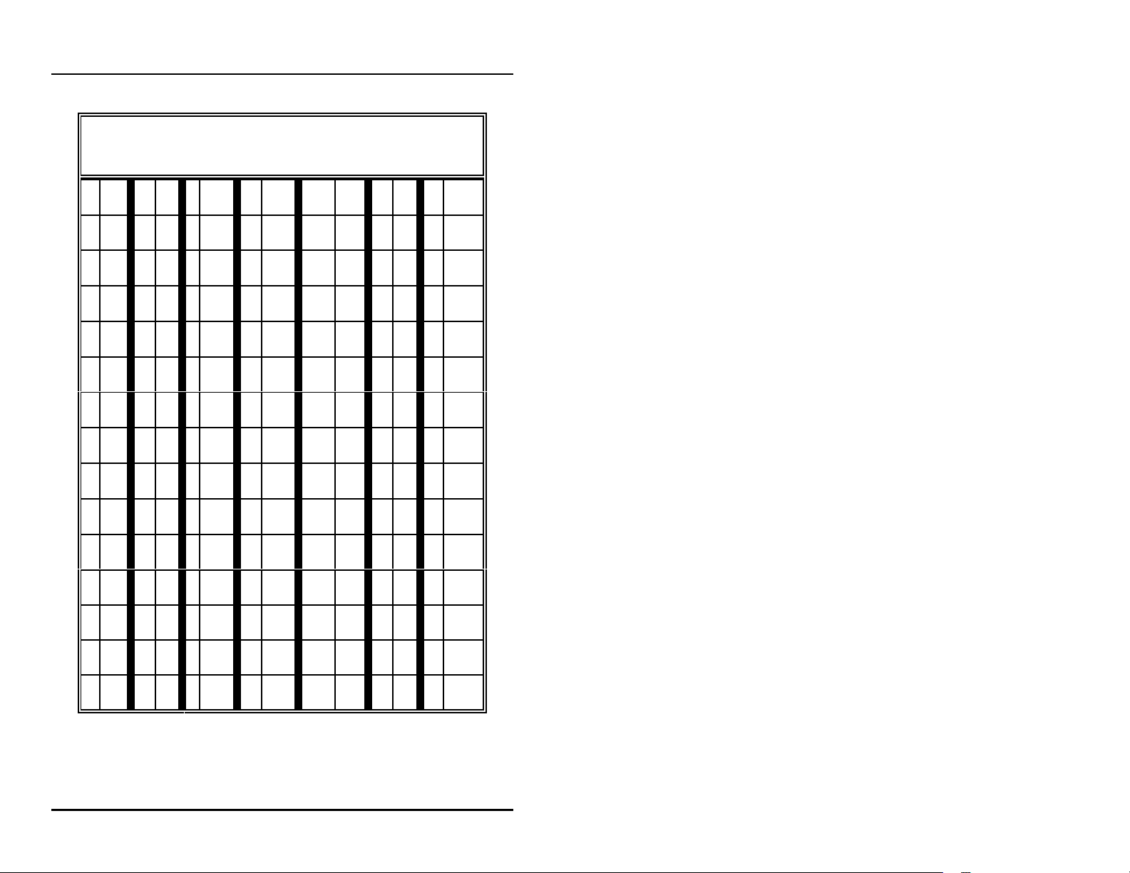
entry. (Refer to Table 6, Print Header Character Codes, for a
numeric code which represents the characters available for your
use on the printer header.) Determine the character you wish to
place in the first position of the header and look up the numeric
code. Enter this numeric code on the keypad and press
<ENTER>
been saved in memory. For each subsequent character, follow
the sequence described above.
. The character will appear on the display, and has
<ENTER>
(Manager only)
.
<7>
on
There are two special numeric codes for the header:
indicates a
header
should cease printing on the current line and go to the
beginning of the next line. The
after the entire header is entered and will tell the C2000 that no
more characters are needed in the header.
new line
. Enter the
in the header;
new line
code at the point where the printer
<01>
is the code for
end of header
code is entered
<10>
‚ 24
end of
Page 31
C2000
Program & Report
Print Header Character Codes
01 = end of header 10 = new line
0 48 F 70 U 85 j 106 y 121 - 45
1 49 G 71 V 86 k 107 z 122 . 46 { 123
2 50 H 72 W 87 l 108 32 / 47 | 124
3 51 I 73 X 88 m 109 ! 33 : 58 } 125
4 52 J 74 Y 89 n 110 " 34 ; 59 ~ 126
5 53 K 75 Z 90 o 111 # 35 < 60
6 54 L 76 a 97 p 112 $ 36 = 61
7 55 M 77 b 98 q 113 % 37 > 62
8 56 N 78 c 99 r 114 & 38 ? 63
9 57 O 79 d 100 s 115 ' 39 @ 64
A 65 P 80 e 101 t 116 ( 40 [ 91
B 66 Q 81 f 102 u 117 ) 41 \ 92
space
<
96
C 67 R 82 g 103 v 118 * 42 ] 93
D 68 S 83 h 104 w 119 + 43 ^ 94
E 69 T 84 i 105 x 120 , 44 _ 95
Table 6: Print Header Character Codes
‚ 25
Page 32

C2000
Special editing features are available for use in this mode:
Program & Report
<ENTER>
curser will increment to the next character in the header.
<SELECT>
curser will go back one character in the header.
<CHANGE>
printer header will be cleared.
<PRINT>
print the header that is programmed.
<MANAGER>
Mode 10 — Read Reports
In Mode 10, totals reports may be generated and displayed. To
enter this mode, enter
<ENTER>
The display will show an
type code. Use the table below to select which type of report
you would like displayed.
1
2
3
4
5
6
7
without entering a numeric code — The display
without entering a numeric code — The display
without entering a numeric code — The entire
without entering a numeric code — The printer will
— Exit Mode 7.
(Manager/Operator)
<10>
on the keypad and press
.
R:0
, prompting you to enter a report
Resettable Totals
Non-Resettable Totals
Shift 0 Totals (current shift)
Shift 1 Totals
Shift 2 Totals
Shift 3 Totals
Polled Pump Totals
‚ 26
Page 33

C2000
Select the report number and enter it on the C2000 keypad; then
<ENTER>
press
in the display. Use the following keys to scroll through the
report.
<ENTER>
<VOLUME>
<CASH PAID>
<CREDIT PAID>
<MANAGER>
. The beginning data for the report is shown
Display next product totals
Display the volume total
Display the cash total
Display the credit total
Exit Mode 10
Program & Report
Mode 11 — Print Reports
Mode 11 allows reports to be generated and printed on the
printer attached to the C2000. To enter this mode enter
on the numeric keypad and press
P:0
will be displayed, prompting you to enter a report type
code. Use the table below to select which type of report you
would like printed by the C2000.
1
Resettable Totals
2
Non-Resettable Totals
3
Shift 0 Totals (current shift)
4
Shift 1 Totals
5
Shift 2 Totals
6
Shift 3 Totals
7
Polled Pump Totals
8
Console Program Information
(Manager/Operator)
<ENTER>
.
<11>
‚ 27
Page 34

C2000
Select the report number and enter it on the C2000 keypad; then
<ENTER>
press
wish to print additional reports, select another report option. Or
<MANAGER>
press
. Data for the report will be printed. If you
to exit Mode 11.
Program & Report
Mode 12 — Clear Resettable Totals
Mode 12 is used to reset resettable totals by clearing them to
zero. Enter
The display will show
resettable totals, proceed by pressing
Press any key to exit Mode 12.
<12>
and press
<ENTER>
press clear
. If you wish to zero all
Mode 97 — Program Operator PIN Code
WARNING: Care should be observed when using this mode.
If the PIN Code is altered, be sure to make note of the new PIN
Code and save in a safe location.
In Mode 97, the Operator PIN Code is viewed and changed.
(The default Operator PIN Code is
<97>
enter
display will show the existing Operator PIN Code. To change
the code, enter the new number (up to 4 digits) on the numeric
keypad and press
appear on the display. To exit this mode, press the
<MANAGER>
on the numeric keypad and press
<ENTER>
key.
1111
. The new Operator PIN code will
(Manager/Operator)
to enter Mode 12.
<CLEAR>
.) To enter this mode,
.
(Manager only)
<ENTER>
. The
‚ 28
Page 35

C2000
Program & Report
Mode 98 — Program Manager PIN Code
WARNING: Care should be observed while using this mode.
If the PIN Code is altered, be sure to make note of the new one
and save in a safe location. remember, all access to program
and report functions is accomplished via this number.
Mode 98 allows the Manager PIN Code to be viewed and
changed. The default Manager PIN Code is
Mode 98, enter
<ENTER>
Code. To change the code, enter the new number (up to 4
digits) on the numeric keypad and press
Manager PIN Code will appear on the display.
To exit Mode 98, press
Mode 99 — Console Diagnostics
Call Progressive International Electronics at 919 821-1323 for
instructions.
<98>
on the numeric keypad and press
. The display will show the existing Manager PIN
<ENTER>
<MANAGER>
.
(Manager only)
(Manager only)
2422
. To enter
. The new
‚ 29
Page 36

C2000
INSTALLATION
Installation
Introduction
The Installation Section contains instructions for installing the
C2000 to electronic fuel pump computers and to peripheral
equipment (PE), such as the point of sale terminal (POS).
Instructions for installing or servicing electronic fuel pumps or
dispensers, and the point of sale terminals are not included in this
manual. (See manufacturer's manual specific to each particular
product for installation/servicing instructions.)
Read the entire installation section of this manual before
attempting to install the C2000.
If further assistance is required, please contact:
PROGRESSIVE INTERNATIONAL ELECTRONICS, INC.
2422 Atlantic Avenue
Raleigh, North Carolina 27604
Phone (919) 821-1323
FAX (919) 821-1325
‚ 30
Page 37

C2000
Installation
General Installation Guidelines
The basic C2000 system consists of several components — the
console, configurator box and cables to interconnect the
components. Refer to Figure 1, which shows a typical layout of
the C2000 system, including attachment to an optional printer.
To begin installation, place the console at the checkout counter of
the station. Note that the console has four threaded inserts on the
bottom for mounting with screws to a cellular telephone stand (not
provided). This will allow the console to be elevated and angled
for efficient use next to the cash register.
Next, locate the configurator box and mount under the counter or
on a wall adjacent to the console, not more than five feet away.
Attach the console/configurator cable to the 15-pin connector on
the back of the C2000. Plug the other end into the input connector
(9-pin) on the configurator box. If a printer is to be used with the
C2000, attach the printer cable to the 25-pin connector on the back
of the printer and the other end to the 9-pin serial port connector
on the back of the console.
Attach the C2000 system to the dispenser data distribution
equipment for the appropriate pump type, as outlined in the
following pages.
Upon completion, apply power to the C2000 console and
configurator box, as well as the printer (if applicable) and
commence programming, as outlined in Program & Report.
‚ 31
Page 38

C2000
Installation
Installation Warnings
Warning:
Code, as well as Federal, State, Local and all applicable codes.
Warning:
Disconnect all power before making installation to prevent
personal injury or equipment damage.
Warning:
explosive atmosphere. All C2000 units must be protected from
severe vibration, extreme temperatures and excessive humidity.
Any peripheral equipment is to be installed over a non-hazardous
location.
Any peripheral equipment connected to the C2000 must be UL
listed and using standard RS232 or RS485 communication.
The C2000
with bonded earth ground.
Installation must comply with the National Electrical
High voltages are present in this equipment.
Do not install C2000 units in a volatile, combustible or
must
be plugged into a dedicated 115 VAC wall socket
‚ 32
Page 39
C2000
Installation
Gilbarco Electronic Fuel Pumps
Read entire installation section before attempting to install system.
Take careful note of warnings in this section before mounting C2000.
Mount the C2000's configurator box on the wall or under the counter so
that no cables are strained.
1. Install the Gilbarco pumps according to the Gilbarco installation
instructions. Connect the pump data wires to the Gilbardo "D"
box according to Gilbarco installation instructions.
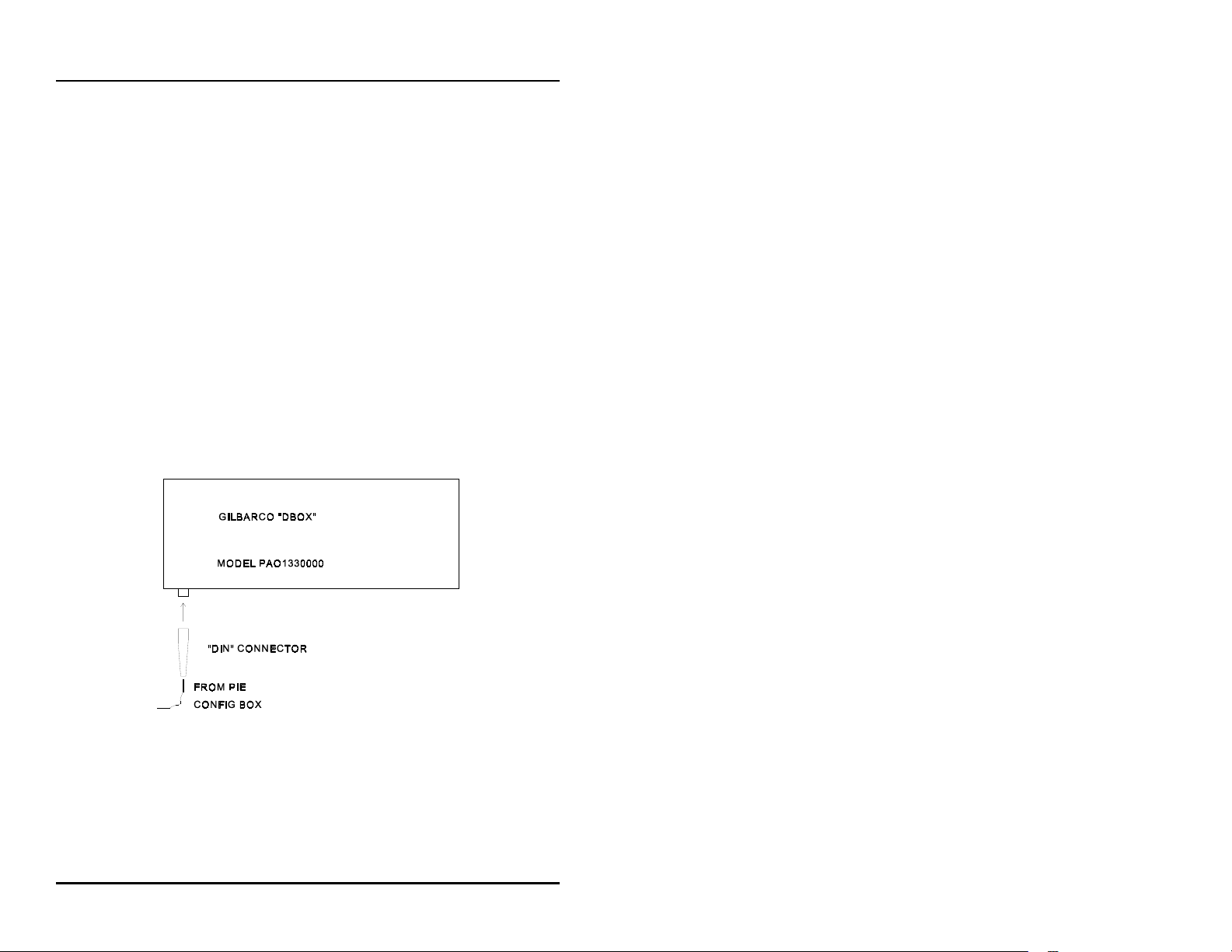
2. Locate the appropriate pump connection cable. Connect the DIN
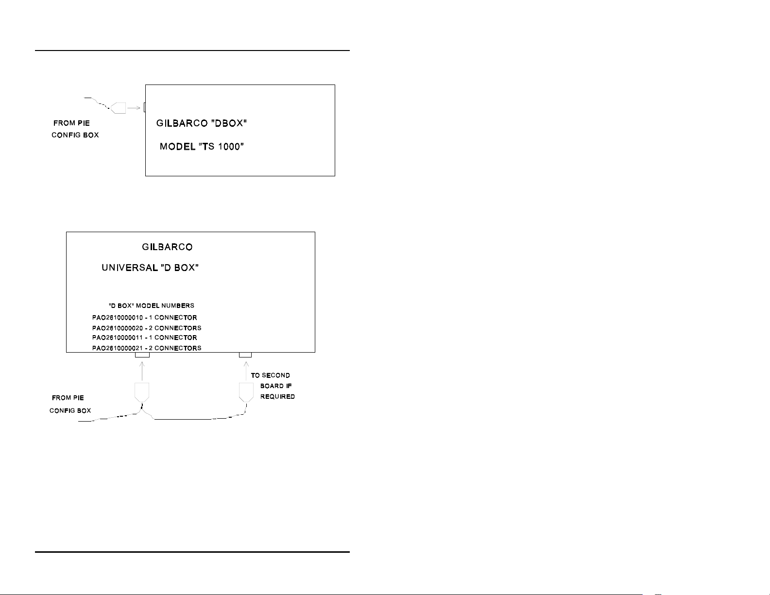
or D-sub connector to the Gilbarco "D" box. The various "D"
box models are illustrated in Figures 4, 5 and 6.
Figure 4: Gilbarco PAO1330000 "D" Box
‚ 33
Page 40
C2000
Installation
Figure 5: Gilbarco TS1000 "D" Box
Figure 6: Gilbarco Universal "D" Box
3. Test all the pumps in stand-alone. Do not proceed until all
pumps run in stand-alone.
‚ 34
Page 41

C2000
Installation
4. Turn all the switches in the Gilbarco "D" box to
Program the pump numbers into the pumps. Switch the
"D" box switches for the pumps that are connected to
NORMAL
NOTE: All Single Product Dispensers (SPDs) must be set for
"grade 1."
.
ISOLATE
.
‚ 35
Page 42
C2000
Installation
Tokheim Electronic Fuel Pumps
Read entire installation section before attempting to install
system. Take careful note of warnings in this section before
mounting C2000.
Mount the C2000's configurator box on the wall or under the
counter so that no cables are strained.
For Pumps Using Tokheim M98 Computer/Power Center:
1. Install the Model 98 Computer/Power Center box and
Tokheim pumps according to Tokheim installation
instructions. Pumps must work in stand-alone before
proceeding. Pumps should be configured in the same
manner as for the Tokheim Model 179 Console.
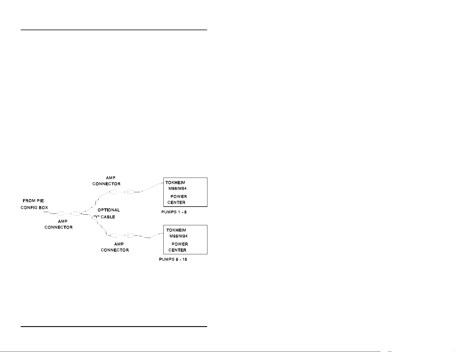
Figure 7: Tokheim 98 Installation
2. Locate the C2000 pump connection cable. This cable has a
DE9S connector with hood on one end and a round
connector on the other end.
‚ 36
Page 43

C2000
3. Attach the C2000 pump connection cable to the connector
on the Tokheim configurator box. Be sure to screwlock
this connector to the Tokheim configurator box with the
screws provided.
4. For systems with eight pumps or less, connect the C2000
pump connection cable directly to the Model 98
Computer/Power Center. For systems with more than eight
pumps (two Model 98 Computer/Power centers) use a "Y"
cable (optional component, available through Progressive
International Electronics) between the Tokheim
configurator box and the Model 98 Computer/Power
Centers.
The connection must not be subjected to harsh
environments such as under water, extreme heat or
extreme cold, etc.
Ensure that cables are screwlocked together.
Installation
5. Connect the wall transformer into a 115 VAC receptacle.
‚ 37
Page 44
C2000
For Pumps Using Tokheim Model 67 Connection Box:
1. Install pumps and connect wires to the Tokheim 67
connection box according to Tokheim instructions.
Configure pumps as for Tokheim MIMS IV.
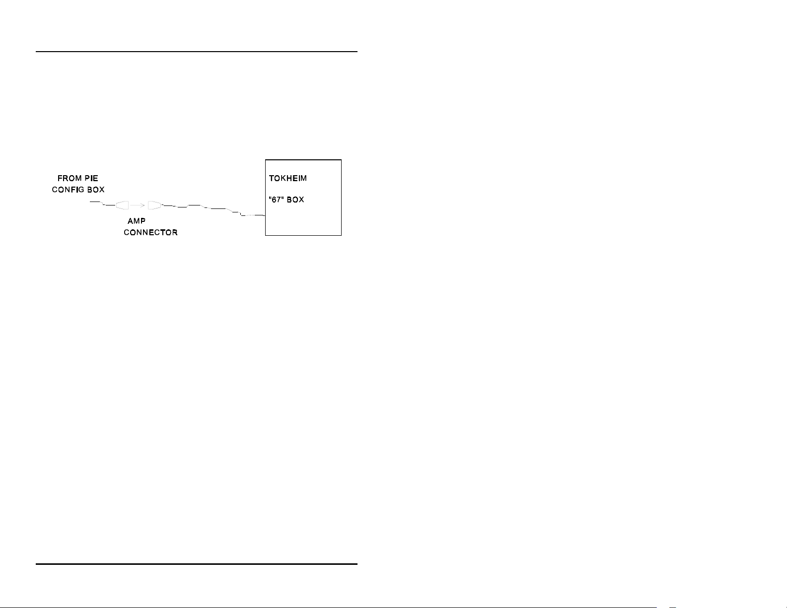
Figure 8: Tokheim 67 Installation
2. Locate the C2000's pump connection cable. This cable has
a DE9S connector with hood on one end and a round
connector on the other end.
Installation
3. Connect the C2000's pump connection to the connector on
the Tohkeim configurator box.
connector to the Tokheim configurator box with the
screws provided.
4. Locate the other end of the C2000's pump connection
cable. Connect the round connector to the cable from the
Tokheim 67 into the connect box. Ensure that this cable
connection is screwlocked together. The connection must
not be subjected to harsh environments such as under
water, extreme heat or extreme cold, etc.
5. Connect the wall transformer into a 115 VAC receptacle.
Be sure to screwlock this
‚ 38
Page 45
C2000
Installation
Kraus Micon 100 Electronic Fuel Pumps
Read entire installation section before attempting to install
system. Take careful note of warnings in this section before
mounting C2000.
Mount the C2000's configurator box on the wall or under the
counter so that no cables are strained.
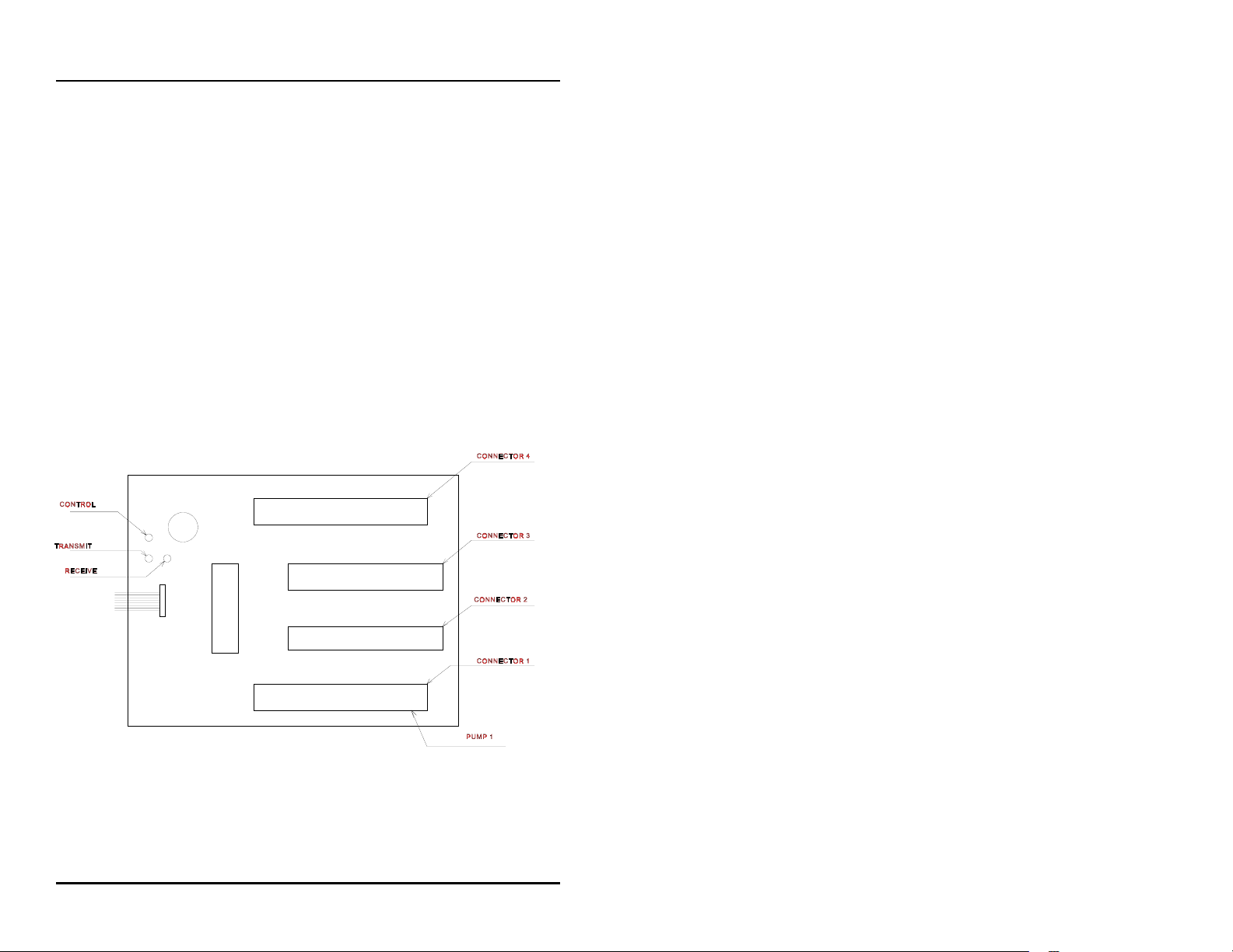
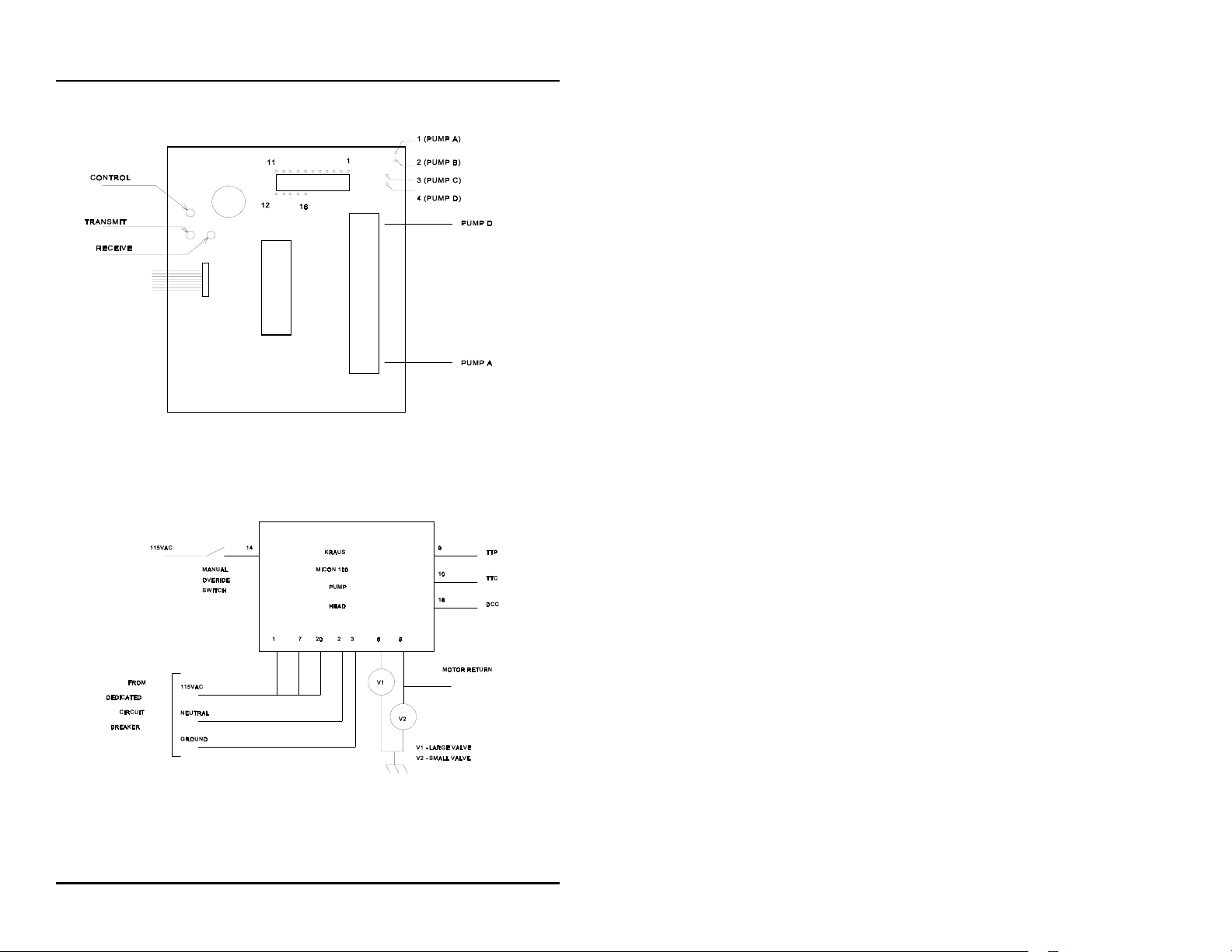
1. Connect the data wires (TTC, TTP, DCC) into the pump
connectors on the configurator box for the Kraus system.
Refer to Figures 9, 10, and 11, as well as Table 6.
Figure 9: Configurator Box for Kraus 16-Hose Systems
‚ 39
Page 46
C2000
Installation
Figure 10: Configurator Box for Kraus 4-Hose Systems
‚ 40
Figure 11: Kraus Micon Pump Head
Page 47
C2000
Installation
PIN
#
1 TTC
2DCC
3 TTP
4 TTC
5DCC
6 TTP
7 TTC
8DCC
9 TTP
10 TTC
11 DCC
12 TTP
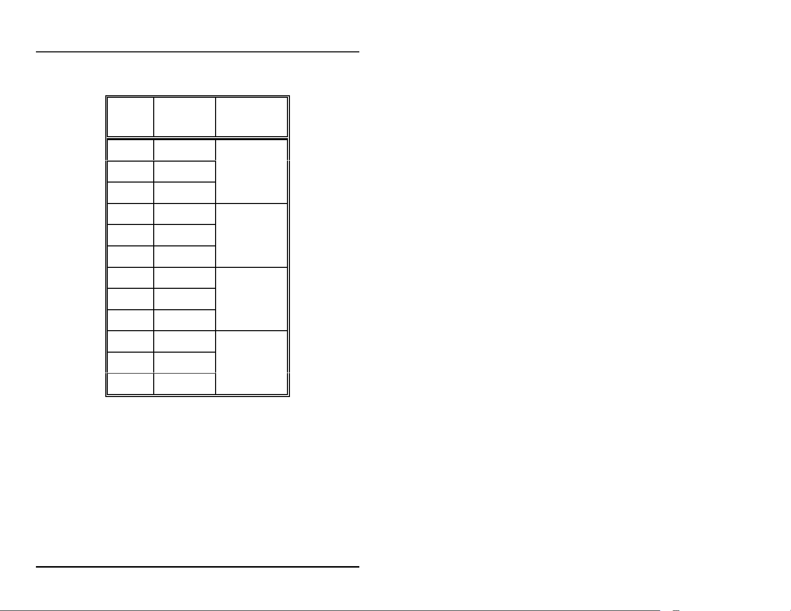
SIGNAL PUMP #
1, 5, 9, 13
2, 6, 10, 14
4, 7, 11, 15
4, 8, 12, 16
Table 6: Kraus Connector Layout
Pumps 1, 2, 3, 4 on connector 1
Pumps 5, 6, 7, 8 on connector 2
Pumps 9, 10, 11, 12 on connector 3
Pumps 13, 14, 15, 16 on connector 4
‚ 41
Page 48
C2000
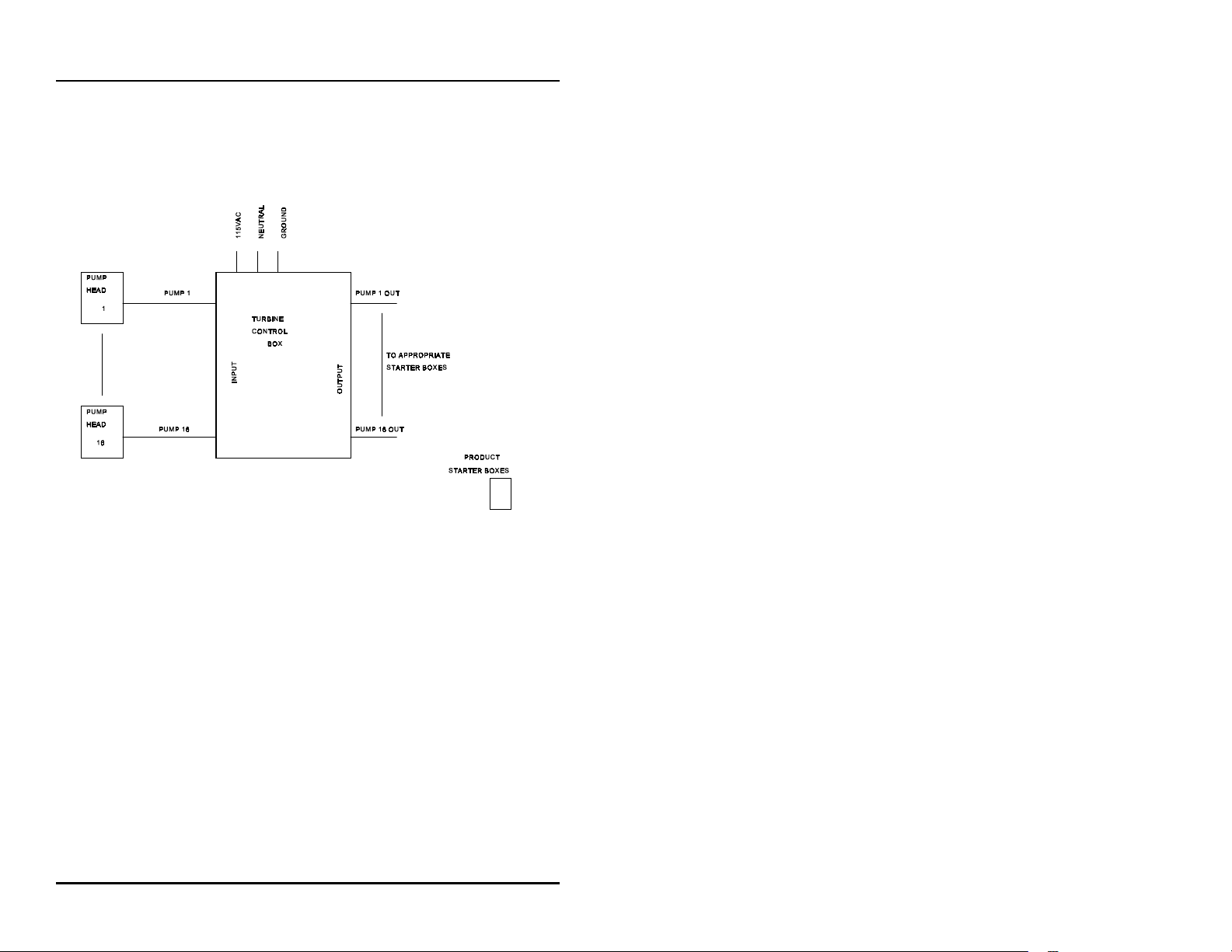
2. If submerged turbine pumps are used, install the optional
turbine relay box. Refer to Figure 12 below.
Installation
Figure 12: Turbine Relay Box for Kraus
3. Connect the wall transformer into a 115 VAC receptacle.
‚ 42
Page 49
C2000
Installation
Wayne/Dresser Electronic Fuel Pumps
Read entire installation section before attempting to install
system. Take careful note of warnings in this section before
mounting C2000.
Mount the C2000's configurator box on the wall or under the
counter so that no cables are strained.
1. Install the Wayne/Dresser pumps according to the
Wayne/Dresser installation instructions. Connect the pump
data wires to the model DD/DY2400/16 connection box
according to the Wayne/Dresser installation instructions.
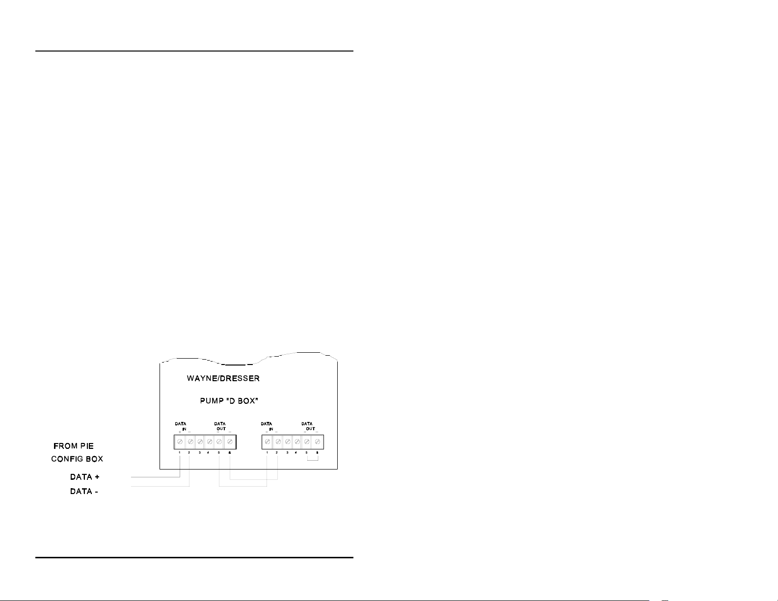
2. Locate the C2000's pump connection cable. Connect the
wires into the Wayne/Dresser connection box, as shown in
Figure 13.
Figure 13: Wayne/Dresser Distribution Box
‚ 43
Page 50

C2000
3. Test all the pumps in stand-alone. Do not proceed until all
pumps run in stand-alone.
4. Turn all the switches in the Wayne/Dresser connection box
BYPASS
to
Switch the "D" box switches for the pumps that are
connected into
5. Connect the wall transformer into a 115 VAC receptacle.
. Program the pump numbers into the pumps.
AUTO
.
Installation
‚ 44
Page 51
C2000
Installation
Bennett Electronic Fuel Pumps
Read entire installation section before attempting to install
system. Take careful note of warnings in this section before
mounting C2000.
Mount the C2000's configurator box on the wall or under the
counter so that no cables are strained.
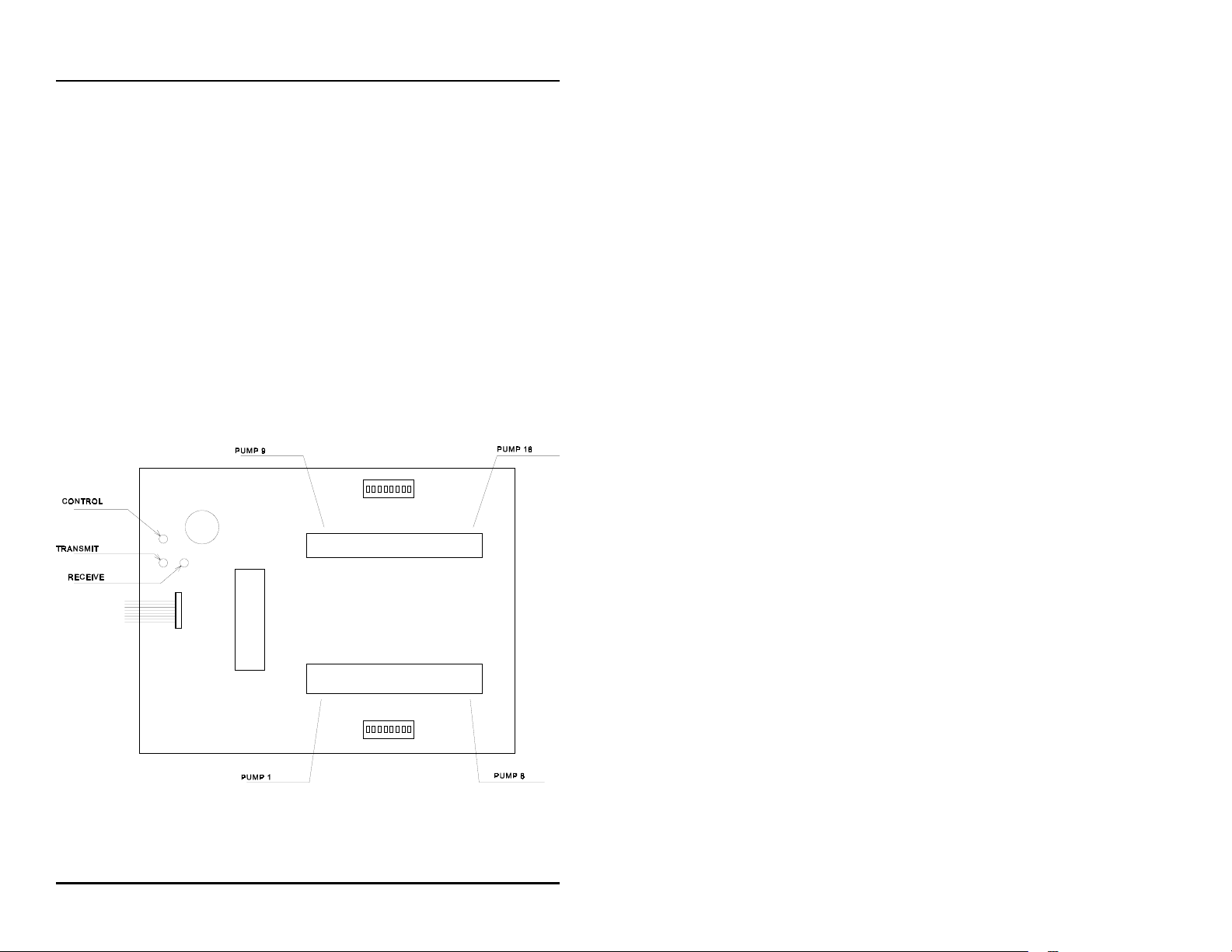
1. Connect the data wires — Orange (+) and Yellow (-) —
into the pump connectors on the Bennett distribution box.
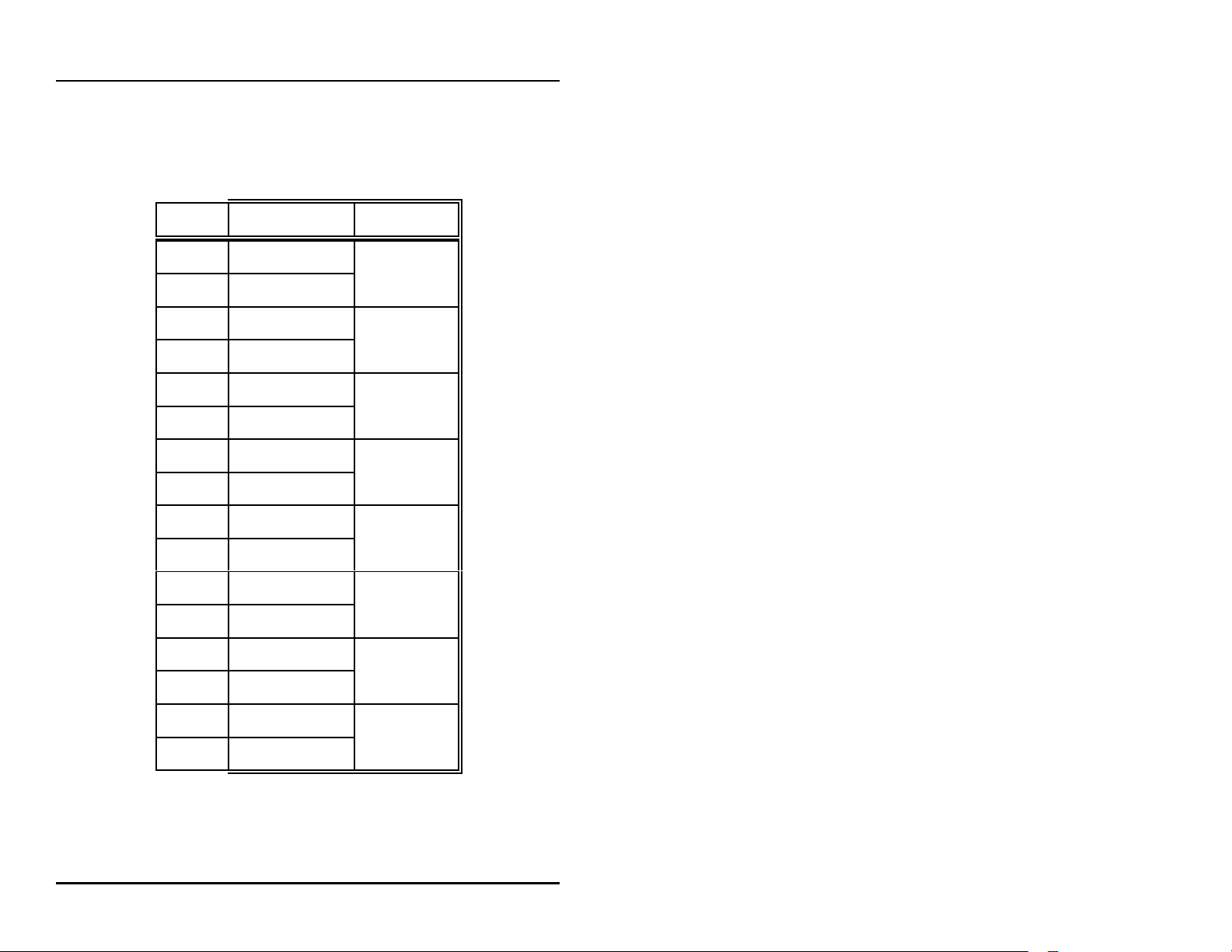
Refer to Table 7 and Figure 14.
Figure 14: Configurator Box for Bennett Systems
‚ 45
Page 52
C2000
Installation
2. Connect the wall transformer into a 115 VAC receptacle.
PIN # SIGNAL PUMP #
1Orange (+)
2 Yellow (-)
3Orange (+)
4 Yellow (-)
5Orange (+)
6 Yellow (-)
7Orange (+)
8 Yellow (-)
1, 9
2, 10
3, 11
4, 12
‚ 46
9Orange (+)
5, 13
10 Yellow (-)
11 Orange (+)
6, 14
12 Yellow (-)
13 Orange (+)
7, 15
14 Yellow (-)
15 Orange (+)
8, 16
16 Yellow (-)
Table 7: Bennett Connector Layout
Page 53

NOTES
‚ 47
Page 54

NOTES
‚ 48
 Loading...