

Page 1
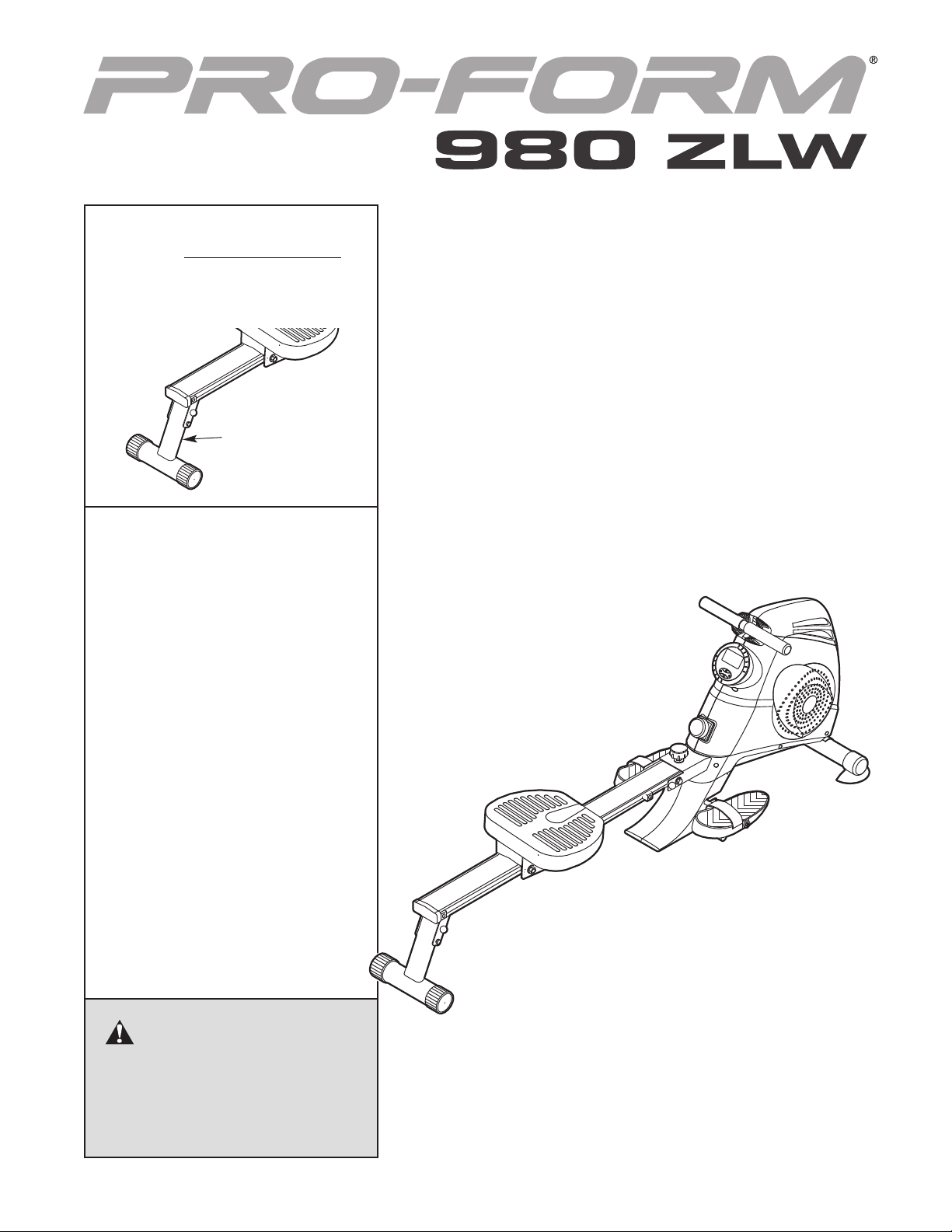
Model No. PIRW34008.0
Serial No.
Write the serial number in the
space above for reference.
Serial Number
Decal
QUESTIONS?
If you have questions, or if parts
are damaged or missing, CONTACT
THE STORE WHERE YOU
PURCHASED THIS PRODUCT.
USER'S MANUAL
CAUTION
Read all precautions and instructions in this manual before using
this equipment. Keep this manual
for future reference.
www.proform.com
Page 2
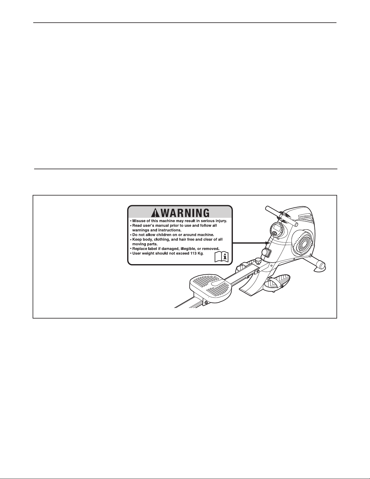
TABLE OF CONTENTS
WARNING DECAL PLACEMENT . . . . . . . . . . . . . . . . . . . . . . . . . . . . . . . . . . . . . . . . . . . . . . . . . . . . . . . . . . . . . .2
MPORTANT PRECAUTIONS . . . . . . . . . . . . . . . . . . . . . . . . . . . . . . . . . . . . . . . . . . . . . . . . . . . . . . . . . . . . . . . .3
I
BEFORE YOU BEGIN . . . . . . . . . . . . . . . . . . . . . . . . . . . . . . . . . . . . . . . . . . . . . . . . . . . . . . . . . . . . . . . . . . . . . .4
ASSEMBLY . . . . . . . . . . . . . . . . . . . . . . . . . . . . . . . . . . . . . . . . . . . . . . . . . . . . . . . . . . . . . . . . . . . . . . . . . . . . . . .5
HOW TO USE THE ROWER . . . . . . . . . . . . . . . . . . . . . . . . . . . . . . . . . . . . . . . . . . . . . . . . . . . . . . . . . . . . . . . .10
MAINTENANCE AND TROUBLESHOOTING . . . . . . . . . . . . . . . . . . . . . . . . . . . . . . . . . . . . . . . . . . . . . . . . . . .13
PART LIST . . . . . . . . . . . . . . . . . . . . . . . . . . . . . . . . . . . . . . . . . . . . . . . . . . . . . . . . . . . . . . . . . . . . . . . . . . . . . .14
EXPLODED DRAWING . . . . . . . . . . . . . . . . . . . . . . . . . . . . . . . . . . . . . . . . . . . . . . . . . . . . . . . . . . . . . . . . . . . .15
ORDERING REPLACEMENT PARTS . . . . . . . . . . . . . . . . . . . . . . . . . . . . . . . . . . . . . . . . . . . . . . . . . .Back Cover
WARNING DECAL PLACEMENT
This drawing shows the
location(s) of the warning
decal(s). If a decal is
missing or illegible, see
the front cover of this
manual and request a
free replacement decal.
Apply the decal in the
location shown. Note:
The decal(s) may not be
shown at actual size.
PROFORM is a registered trademark of ICON IP, Inc.
2
Page 3

IMPORTANT PRECAUTIONS
WARNING: To reduce the risk of serious injury, read all important precautions and
instructions in this manual and all warnings on your rower before using your rower. ICON assumes
o responsibility for personal injury or property damage sustained by or through the use of this
n
product.
1. Before beginning any exercise program,
consult your physician. This is especially
important for persons over age 35 or persons with pre-existing health problems.
2. It is the responsibility of the owner to ensure
that all users of the rower are adequately
informed of all precautions.
3. The rower is intended for home use only. Do
not use the rower in a commercial, rental, or
institutional setting.
4. Keep the rower indoors, away from moisture
and dust. Place the rower on a level surface,
with a mat beneath it to protect the floor or
carpet. Make sure that there is at least 2 ft.
(0.6 m) of clearance on each side of the
rower.
5. Inspect and properly tighten all parts regularly. Replace any worn parts immediately.
6. Keep children under age 12 and pets away
from the rower at all times.
7. The rower should not be used by persons
weighing more than 250 lbs. (113 kg).
8. Wear appropriate exercise clothes when
exercising; do not wear loose clothes that
could become caught on the rower. Always
wear athletic shoes for foot protection.
9. Keep your hands away from moving parts.
10. Keep your back straight while using the
rower; do not arch your back.
11. Over exercising may result in serious injury
or death. If you feel faint or if you experience
pain while exercising, stop immediately and
cool down.
12. Use the rower only as described in this manual.
3
Page 4
BEFORE YOU BEGIN
Thank you for selecting the PROFORM®980 ZLW
rower. Rowing is an effective exercise for toning the
body, strengthening the muscles, and building the car-
iovascular system. The 980 ZLW is designed to let
d
you enjoy this effective exercise in the convenience
nd privacy of your home.
a
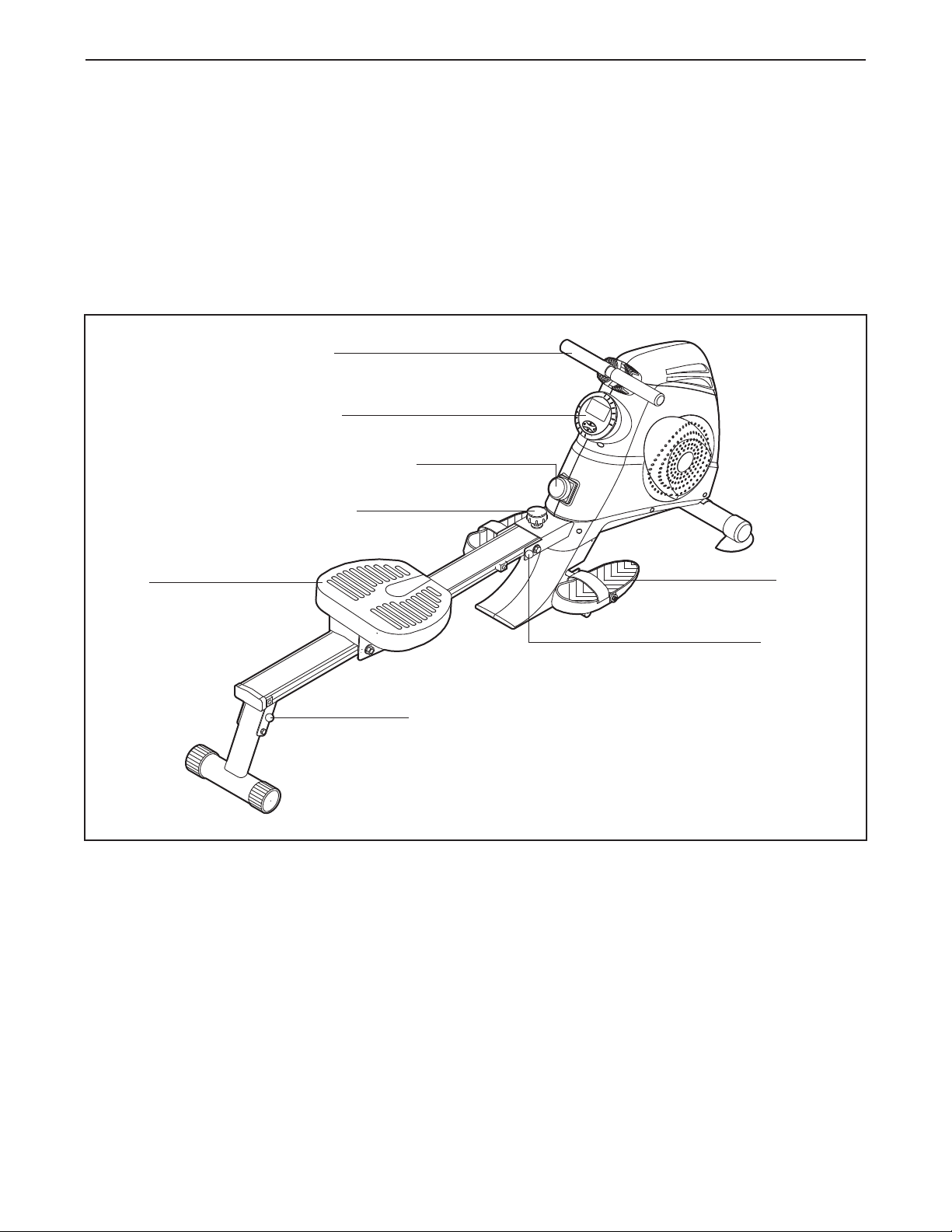
For your benefit, read this manual carefully before
you use the rower. If you have questions after read-
Handle
Console
Resistance Control
Lock Knob
Seat
ing this manual, please see the front cover of this
manual. To help us assist you, note the product model
number and serial number before contacting us. The
odel number and the location of the serial number
m
decal are shown on the front cover of this manual.
Before reading further, please familiarize yourself with
the parts that are labeled in the drawing below.
Footrest
Stabilizer Pin
Frame Pin
4
Page 5
ASSEMBLY
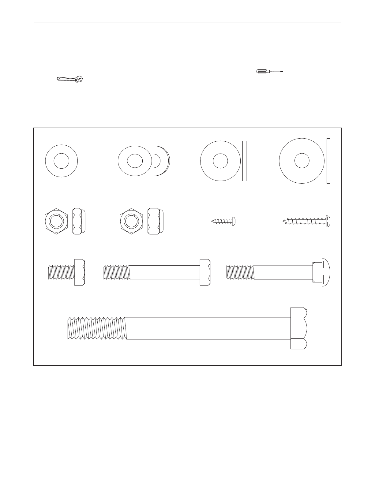
M8 Locknut
(73)–4
M8 Curved
Washer (74)–2
M8 Carriage Bolt
(82)–2
M8 x 16mm
Washer (75)–6
M8 x 55mm Hex
Screw (83)–2
M8 x 15mm Hex
Screw (86)–4
M8 x 23mm
Washer (76)–2
1/2" x 127mm Hex Bolt (88)–1
M8 x 26mm
Washer (77)–1
Jam Nut
(78)–1
M4 x 25mm
Screw (84)–2
M3 x 12mm
Screw (42)–2
Assembly requires two persons. Place all parts of the rower in a cleared area and remove the packing materials. Do not dispose of the packing materials until assembly is completed.
In addition to the included tool(s), assembly requires a Phillips screwdriver and an adjustable
wrench .
As you assemble the rower, use the drawings below to identify small parts. The number in parentheses below
each drawing is the key number of the part, from the PART LIST near the end of this manual. The number following the parentheses is the quantity needed for assembly. Note: If a part is not in the hardware kit, check
to see if it has been preassembled.
5
Page 6

.
1
To make assembly easier, read the
nformation on page 5 before you begin.
i
1
While a second person lifts the front of the
Frame (1), attach the Front Stabilizer (44) to the
Frame with two M8 Carriage Bolts (82), two M8
Curved Washers (74), and two M8 Locknuts
73).
(
2. While a second person lifts the rear of the
Frame (1), slide the Footrest Bracket (46) onto
the bracket on the underside of the Frame.
Attach the Footrest Bracket (46) to the Frame
(1) with two M8 x 55mm Hex Screws (83) and
two M8 x 16mm Washers (75).
74
73
74
1
44
82
2
1
46
75
83
75
6
Page 7

3. Slide the Footrest Bracket Cover (48) onto the
Footrest Bracket (46).
ip: Avoid pinching the Extension Wire (90).
T
Attach the Footrest Bracket Cover (48) to the
ight and Left Shields (2, 3) with two M3 x
R
12mm Screws (42).
3
void pinching the
A
Extension Wire (90)
42
3
2
90
4. Orient the Seat (52) and the Rail (49) as shown.
Then, slide the Seat onto the Rail.
Attach a Bumper (80) to each side of the Rail
(49) with an M4 x 16mm Screws (84).
Press the Rail Cap (89) onto the end of the Rail
(49).
5. Attach the Rear Stabilizer (62) to the underside
of the Rail (49) with four M8 x 15mm Hex
Screws (86) and four M8 x 16mm Washers
(75).
48
4
84
80
52
89
5
46
42
49
80
84
49
75
86
75
86
62
7
Page 8

6. Insert the Footrest Axle (68) into the upper hole
in the Footrest Bracket (46) and center it.
rient the Footrests (71) as shown. Slide a
O
Footrest onto each end of the Footrest Axle
68).
(
Slide a Plastic Bushing (79) and an M8 x 23mm
Washer (76) onto each end of the Footrest Axle.
Then, tighten an M8 Locknut (73) onto each
end of the Footrest Axle.
Insert the Rest Bar (69) into the lower hole in
the Footrest Bracket (46) and center it.
Press a Rest Pad (81) onto each end of the
Rest Bar (69).
6
76
73
79
81
71
69
46
68
81
71
79
76
73
7. While a second person holds the Rail (49) near
the Frame (1), connect the Extension Wire (90)
to the Reed Switch Wire (41).
Insert the excess wire into the Rail (49).
Tip: Avoid pinching the wires. Position the
Rail (49) inside the bracket on the Frame (1).
Insert a 1/2" x 127mm Hex Bolt (88) through the
Frame (1) and the Rail (49). Slide an M8 x
26mm Washer (77) onto the Hex Bolt and then
tighten a Jam Nut (78) onto the Hex Bolt.
Insert the Frame Pin (87) through the Frame (1)
and the Rail (49). Then, tighten the Lock Knob
(6).
8. The Console (72) can use two AA batteries (not
included); alkaline batteries are recommended.
IMPORTANT: If the Console has been
exposed to cold temperatures, allow it to
warm to room temperature before inserting
batteries. Otherwise, you may damage the
console displays or other electronic components. Remove the battery cover, insert the bat-
teries into the battery compartment, and reattach the battery cover. Make sure to orient the
batteries as shown by the diagram inside
the battery compartment.
7
Avoid pinching
41
49
8
the wires
78
77
90
72
6
1
88
87
Battery
Cover
8
Page 9

9. While a second person holds the Console (72)
near the Frame (1), connect the console wire to
the Extension Wire (90).
Insert the excess wire into the Frame (1).
Tip: Avoid pinching the wires. Press the
Console (72) into the Frame (1).
10. Make sure that all parts of the rower are properly tightened. Note: Some hardware may be left over after
assembly is completed. To protect the floor or carpet from damage, place a mat under the rower.
9
Console
72
W
ire
90
1
Avoid
pinching
he wires
t
9
Page 10

HOW TO USE THE ROWER
HOW TO FOLD AND UNFOLD THE ROWER
When the rower is not in use, the rail and the stabilizer can be folded out of the way.
. Loosen the lock knob and remove the frame pin.
1
ock Knob
L
2. Raise the rail until it is folded against the frame.
Then, reinsert the frame pin.
3. Remove the stabilizer pin and move the stabilizer downward until it is folded against the rail.
Reinsert the stabilizer pin.
To unfold the rower, reverse the steps listed above.
HOW TO ADJUST THE RESISTANCE
To increase the resistance of the handle, turn the
resistance control clockwise; to decrease the resistance, turn the resistance control counterclockwise.
IMPORTANT: Stop turning the knob when turning
becomes difficult, or you may damage the rower.
Rail
Frame Pin
Stabilizer Pin
Stabilizer
Resistance
Control
10
Page 11

HOW TO EXERCISE ON THE ROWER
Sit on the seat, facing the footrests. Place your feet
n the footrests and adjust the straps to fit your feet.
i
Hold the handle with an overhand grip. Correct row-
ng form consists of three phases:
i
1. The first phase is the CATCH. Slide the seat for-
ward until your knees are almost touching your
chest. Pull the handle until your hands are close
to your feet.
2. The second phase is the DRIVE. Push backward
using your legs. Keep your back straight. Lean
back slightly at the hips (not at the waist) and
begin pulling the handle toward your chest. Keep
your elbows outward.
3. The third phase is the FINISH. Your legs should
be nearly straight. Continue to pull the handle
until your hands are even with your chest.
After the finish phase, extend your arms forward
and pull the seat forward using your legs. Repeat,
moving through all three phases with a smooth,
fluid motion. Remember to breathe normally as you
row—never hold your breath.
Seat
Footrests
andle
H
11
Page 12

FEATURES OF THE CONSOLE
3. Set a workout goal, if desired.
The console features five modes that provide instant
xercise feedback during your workouts:
e
can—Displays the Time, Count, Total Count, and
S
Calories modes in a repeating cycle.
Time—Displays the elapsed time. Note: If you set a
time goal (see step 3), this mode will display the time
remaining in your workout.
Count—Displays the number of repetitions completed
during the current workout. Note: If you set a count
goal (see step 3), this mode will display the number of
repetitions remaining in your workout.
Total Count—Displays the total number of repetitions
completed since the Total Reset button was last
pressed.
Calories—Displays the approximate number of calories you have burned. Note: If you set a calorie-burning goal (see step 3), this mode will display the number of calories still to be burned in your workout.
HOW TO USE THE CONSOLE
To set a time, count, or calorie-burning goal for
our workout, press the Mode button repeatedly
y
until the Time, Count, or Calories mode is select-
d.
e
Next, press the Set button repeatedly to set the
desired goal.
4. Begin rowing and follow your progress with
the display.
As you exercise, the console will provide instant
feedback about your workout.
If you have set a workout goal, a tone will sound
for several seconds when you reach your goal.
5. Reset the console, if desired.
To reset the Time, Count, or Calories mode to
zero, press the Reset button while that mode is
selected.
To reset all modes to zero and restart the console,
press the Total Reset button.
Note: Before using the console, make sure that batteries are installed (see assembly step 8 on page 8). If
there is a sheet of clear plastic on the display, remove
the plastic.
1. Turn on the console.
Press a button on the console or begin rowing to
turn on the console.
2. Select a mode for display.
Press the Mode button repeatedly to select the
desired mode for display.
6. When you are finished exercising, the console
will turn off automatically.
If the seat does not move and the console buttons
are not pressed for a few minutes, the console will
turn off automatically.
12
Page 13

MAINTENANCE AND TROUBLESHOOTING
Inspect and tighten all parts of the rower regularly.
eplace worn parts immediately.
R
To clean the rower, use a damp cloth and a small
amount of mild soap. IMPORTANT: To avoid damage
to the console, keep liquids away from the console and keep the console out of direct sunlight.
HOW TO STORE THE ROWER
The rower can be stored in a folded position to conserve space (see HOW TO FOLD AND UNFOLD THE
ROWER on page 10). Store the rower in a location
where children cannot tip it. Remove the batteries
from the console when storing the rower.
CONSOLE TROUBLESHOOTING
If the console does not function properly, the batteries
should be replaced. Most problems are the result of
drained batteries. See assembly step 8 on page 8 for
battery installation instructions.
13
Page 14

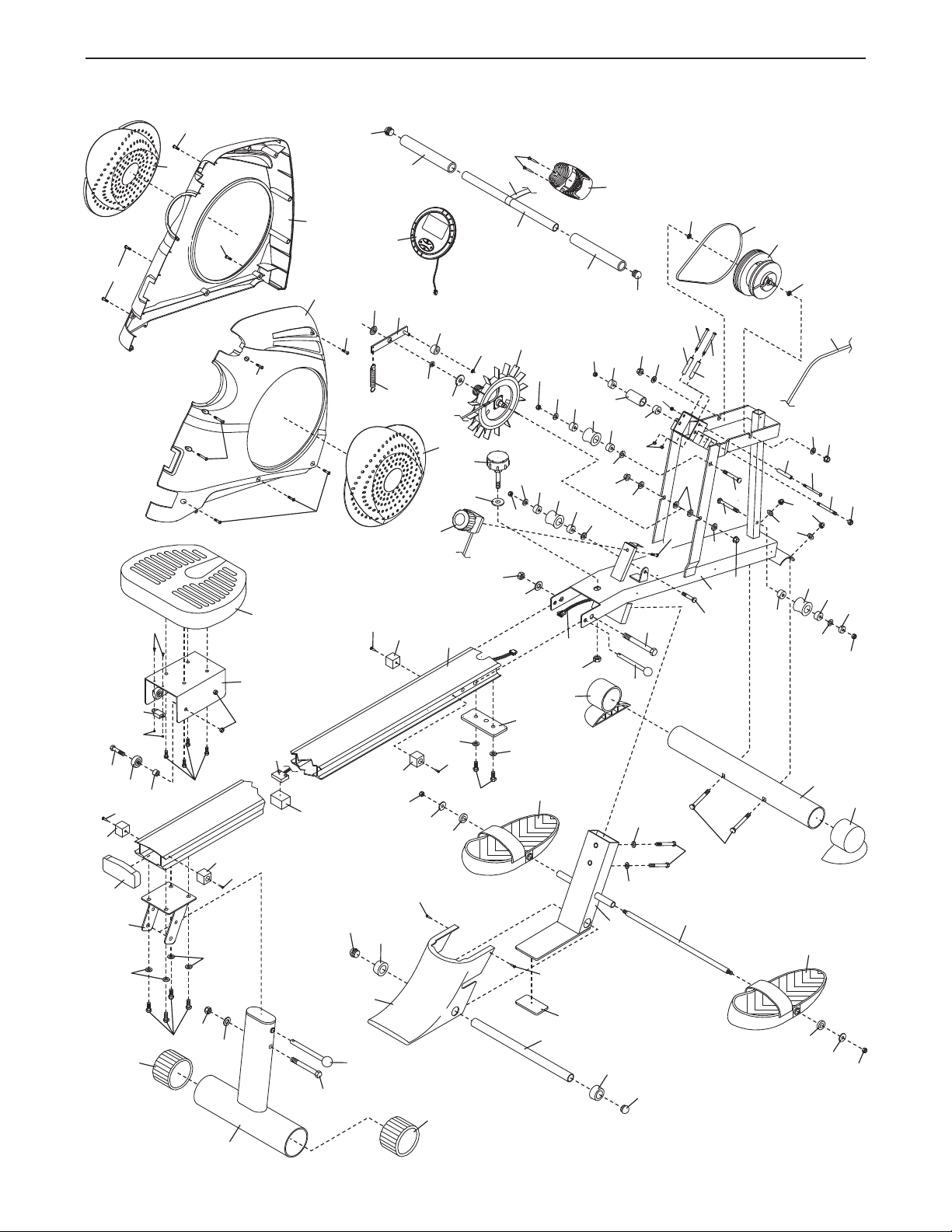
PART LIST—Model No. PIRW34008.0 R0310A
Key No. Qty. Description Key No. Qty. Description
11Frame
2
31Left Shield
41Right Shield Cover
51Left Shield Cover
61Lock Knob
71Knob Washer
81Resistance Control/Cable
91Idler Roller
10 2 Foam Grip
11 1 Handle
12 2 Handle Cap
13 1 Handle Rest
14 1 Fan
15 1 Pulley
16 1 Drive Belt
17 1 Strap
18 1 Elastic Rope
19 3 Roller
20 8 Bearing
21 1 1/2" Nut
22 1 Bushing
23 4 Acorn Nut
24 9 M10 Washer
25 1 C-clip
26 1 Idler Arm
27 1 Tension Spring
28 1 Hat Washer
29 1 M4 x 18mm Washer
30 2 Thin Nut
31 1 Large Plastic Roller
32 3 Small Plastic Roller
33 3 M6 Locknut
34 1 M8 x 80mm Stud
35 1 M8 x 40mm Carriage Bolt
36 1 M8 x 50mm Carriage Bolt
37 1 M8 x 63mm Carriage Bolt
38 3 M6 x 70mm Bolt
39 2 M4 x 16mm Screw
40 6 5/8" Screw
41 1 Reed Switch/Wire
42 2 M3 x 12mm Screw
43 1 30mm Washer
44 1 Front Stabilizer
45 2 Front Stabilizer Cap
46 1 Footrest Bracket
1 Right Shield
47 1 EVA Plate
8 1 Footrest Bracket Cover
4
49 1 Rail
50 1 Plate
51 1 Foam Block
52 1 Seat
53 1 Seat Carriage
54 4 1/4" x 1/2" Seat Screw
55 4 M8 x 28mm Bolt
56 4 Carriage Wheel
57 4 Carriage Bushing
58 2 M3 x 10mm Bolt
59 1 Seat Magnet
60 2 M3 Nut
61 1 Rear Stabilizer Bracket
62 1 Rear Stabilizer
63 2 Rear Stabilizer Cap
64 1 Stabilizer Pin
65 2 M4 x 16mm Screw
66 1 3/8" Locknut
67 1 3/8" Bolt
68 1 Footrest Axle
69 1 Rest Bar
70 2 Rest Cap
71 2 Footrest
72 1 Console
73 13 M8 Locknut
74 2 M8 Curved Washer
75 11 M8 x 16mm Washer
76 2 M8 x 23mm Washer
77 1 M8 x 26mm Washer
78 1 Jam Nut
79 2 Plastic Bushing
80 4 Bumper
81 2 Rest Pad
82 2 M8 Carriage Bolt
83 2 M8 x 55mm Hex Screw
84 7 M4 x 25mm Screw
85 1 M5 x 20mm Screw
86 6 M8 x 15mm Hex Screw
87 1 Frame Pin
88 1 1/2" x 127mm Hex Bolt
89 1 Rail Cap
90 1 Extension Wire
*–Userʼs Manual
*–Assembly Tool
Note: Specifications are subject to change without notice. For information about ordering replacement parts,
please see the back cover of this manual. *These parts are not illustrated.
14
Page 15
1
2
3
4
5
6
7
8
10
10
11
12
1
3
15
16
1
7
18
19
9
19
19
20
20
20
20
20
20
20
20
21
24
23
23
23
23
43
24
24
25
26
28
27
29
14
30
30
12
31
32
32
32
33
33
34
35
36
37
38
38
38
39
65
40
40
40
84
65
84
44
45
45
46
47
48
49
50
51
52
53
54
55
56
57
58
59
60
61
62
63
63
64
24
66
67
68
69
70
70
72
71
71
73
73
73
73
73
73
73
73
73
74
75
75
75
75
75
75
76
76
77
78
79
79
80
80
80
80
81
81
82
83
42
42
84
84
86
84
86
87
88
89
84
41
90
85
75
75
24
24
24
75
22
24
EXPLODED DRAWING—Model No. PIRW34008.0 R0310A
15
Page 16

ORDERING REPLACEMENT PARTS
To order replacement parts, see the front cover of this manual. To help us assist you, please be prepared to
rovide the following information when contacting us:
p
• the model number and serial number of the product (see the front cover of this manual)
the name of the product (see the front cover of this manual)
•
• the key number and description of the replacement part(s) (see the PART LIST and the EXPLODED
DRAWING near the end of this manual)
Part No. 282415 R0310A Printed in Taiwan © 2010 ICON IP, Inc.
 Loading...