

Page 1
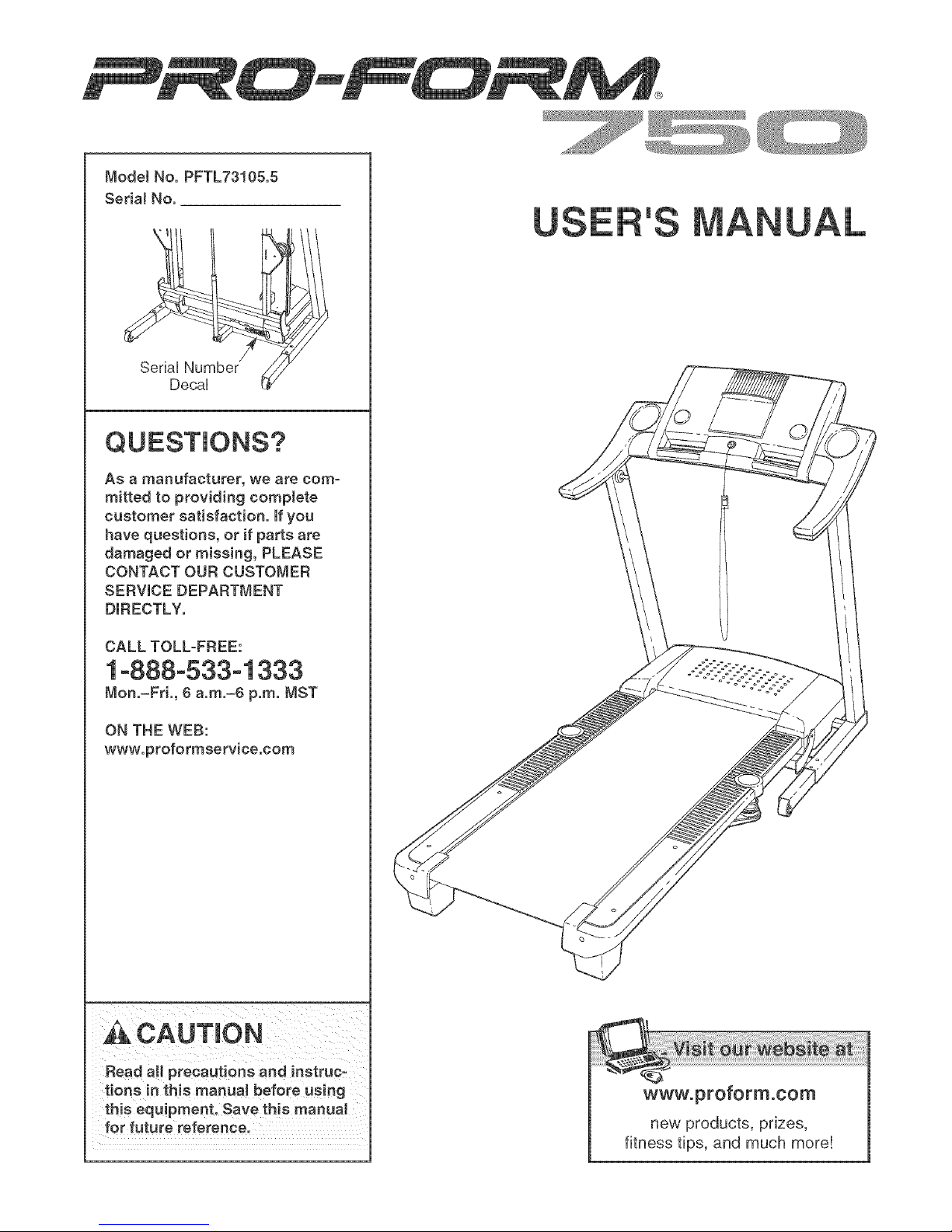
ModelNo.PFTL73105.5
Seda!No.
SeriaU
DecaU
Asamanufacturer,we are com-
mitted to providing complete
customer satisfaction, if you
have questions, or if parts are
damaged or missing, PLEASE
CONTACT OUR CUSTOMER
SERVICE DEPARTMENT
DIRECTLY.
'S
CALL TOLL-FREE:
1-888-533-1333
Mon.=Fd., 6 a.m.=6 p.m. MST
ON THE WEB:
www.proformservice.com
CAUTION
Read all precautions and instruc-
tions in this manual before using
this equipment. Save this manual
for future reference.
wwwoproformooom
new products, prizes,
fitness tips, and much more!
Page 2

TABLE OF CONTENTS
iMPORTANT PRECAUTIONS ................................................................ 3
BEFORE YOU BEGIN ...................................................................... 5
ASSEMBLY ............................................................................... 6
OPERATHON AND ADJUSTMENT ............................................................ 10
HOW TO FOLD AND MOVE THE TREADMHLL .................................................. 20
TROUBLESHOOTHNG ..................................................................... 22
CONDiTiONiNG GUiDELiNES ............................................................... 24
PART LiST .............................................................................. 26
ORDERING REPLACEMENT PARTS .................................................. Back Cover
Note: An EXPLODED DRAWING is attached in the center of this manual,
PROFORM is a registered trademark of iCON IP, Inc,
2
Page 3

iMPORTANT PRECAUTIONS
WARN ING: Toreducethe.ekofburns,f ro,electdcchock,o,injurytopersona,readthe
following important precautions and information before operating the treadmill.
1. it is the responsibility of the owner to ensure ......... local electronics store.
that all users of this treadmill are adequately
informed of all warnings and precautions.
2. Use the treadrniH only as described.
3. Place the treadmill on a leveJsurface, with at
least eight feet of clearance behind it and two
feet on each side. Do not place the treadmill
on any surface that bJocks air openings. To
protect the floor or Carpet from damage, place sot away from heated surfaces.
a mat under the treadrni&
4. Keep the treadrniH indoors, away from mois-
ture and dust. Do not put the treadmill in a
garage or covered patio, or near water.
De not operate the treadmill where aerosol not working property.)
products are used or where oxygen is being
administered. 15. Read, understand, and test the emergency
=
Keep children under the age of 12 and pets
away from the treadmill at all times.
.
The treadmill should be used only by persons
weighing 300 pounds or less.
12. Failure to use a properJy functioning surge
suppressor eouJd result in damage to the con-
trol system of the treadmill, if the control eye-
tern is damaged, the waJking belt may change
speed, acceJerate, or stop unexpectedly,
which may result in a fall and serious injury.
13. Keep the power cord and the surge suppres-
14. Never move the walking beJt while the power
is turned off. Do not operate the treadmill if
the power cord or plug is damaged, or if the
treadmill is not working properly. (See TROUo
BLESHOOTmNG on page 22 if the treadmill is
stop procedure before using the treadmill (see
HOW TO TURN ON THE POWER on page t2).
l& Never start the treadmilJ whiJe you are stand=
ing on the walking beJt. Always hoJd the
handrails while using the treadmill
Never allow more than one person on the
treadmill at a time.
9=
Wear appropriate exercise clothes when
using the treadmill Do not wear loose clothes
that could become caught in the treadmill.
AtHetic support clothes are recommended for
both men and women. A/ways wear athletic
shoes. Never use the treadmillw#h bare feet,
wearing only"stockings,ofinsandals.
10. When connecting the power cord (see page
10), plug the power cord into a surge sup-
pressor (not included) and pJugthe surge
suppressor into a grounded circuit capable of
carrying !5 or more amps. No other appliance
should be on the same circuit. Do not use an
extensioncord.
11. Use only a singJe-outiet surge suppressor
that meets aH of the specifications described
on page 10. To purchase a surge suppressor,
see your local PROFORM dealer or call the
toHofree telephone number on the front cover
of this manual and order part number 146148,
17. The treadmill is capable of high speeds.
Adjust the speed in small increments to avoid
sudden jumps in speed.
18. The puJse sensor is not a medical device.
Various factors, including the user's move-
ment, may affect the accuracy of heart rate
readings. The puJse sensor is intended only
as an exercise aid in determining heart rate
trends ingeneral
19. Never leave the treadmill unattended while it
is running. Always remove the key, unplug
the power cord, and switch the reset/off cir-
cuit breaker to the off position when the
treadmill is not in use. {See the drawing on
page 5 for the location of the circuit breaker.)
26. Do not attempt to raise, lower, or move the
treadmill unti_ it is properly assembled. (See
ASSEMBLY on page & and HOW TO FOLD
AND MOVE THE TREADMILL on page 26.)
You must be able to safe_y Hft 45 pounds (26
kg) to raise, _ower, or move the treadmill.
Page 4
21.When folding or moving the treadmill, make
sure that the storage latch is fully dosed°
22. inspect and properly tighten aH parts of the
treadmill regularly.
23. Never insert any object into any opening.
treadmill, and before performing the mainte=
nance and adjustment procedures described in
this manual. Never remove the motor hood un=
lees instructed to do so by an authorized ser=
vice representative. Servicing other than the
procedures in this manual should be performed
by an authorized service representative only.
=4.DANGER: Always,nplugthepower
25. This treadmill is intended for in=home use
cord immediately after use, before cleaning the onJy. Do not use this treadmill in a commer-
cial, rental, or institutional setting.
,&WARN ING: Beforebog_on_ngtheeoranyexerciseprogram,consultyourphye_c_an.Th_s
is especially important for persons over the age of 35 or persons with pro=existing health problems.
Read aH instructions before using, iCON assumes no responsibility for personal injury or property
damage sustained by or through the use of this product.
SAVE THESE iNSTRUCTIONS
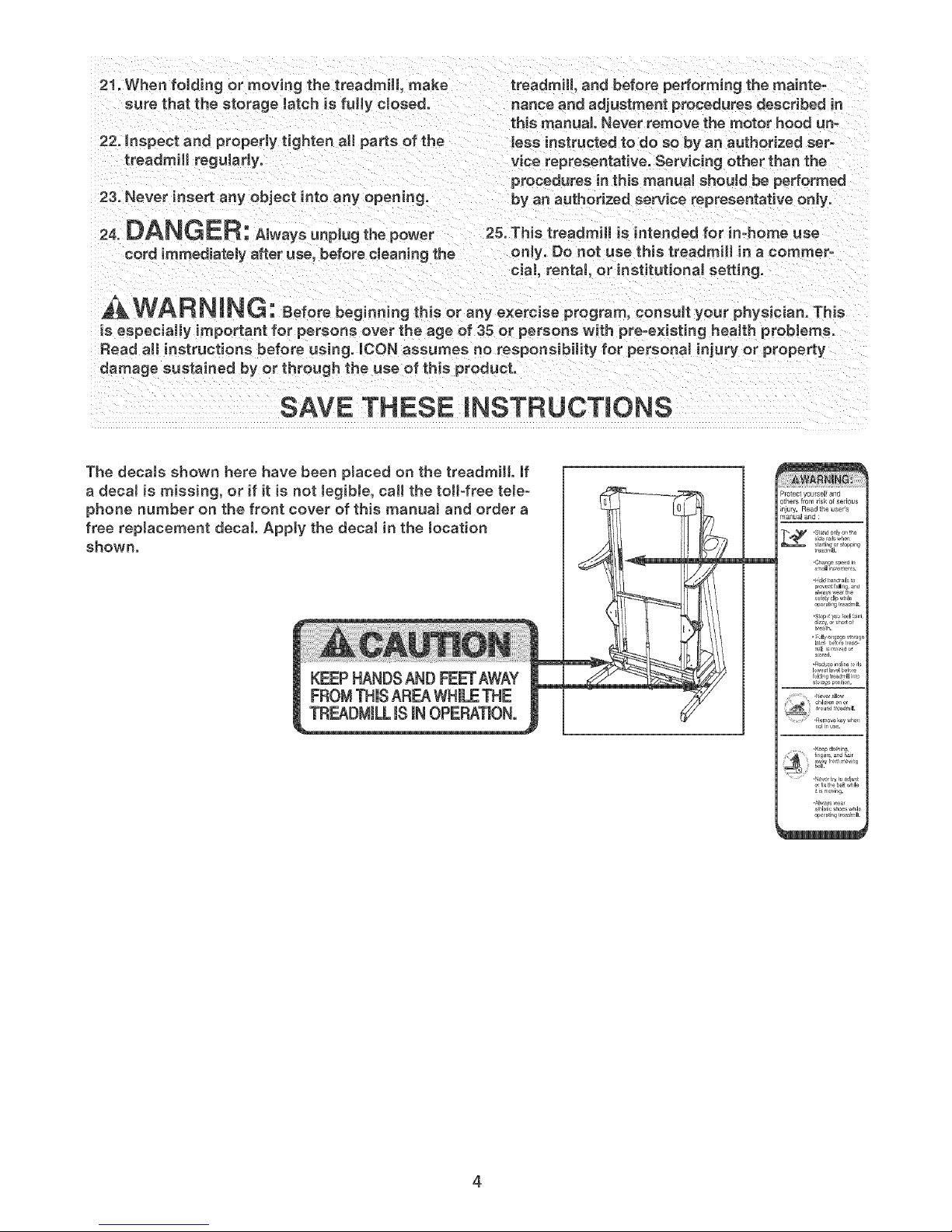
The decals shown here have been placed on the treadmill if
a decaJ is missing, or if it is not JegibJe, call the toil-free tele-
phone number on the front cover of this manuaJ and order a
free replacement decal Apply the deca! in the tocation
shown.
KEEPHANDSANDFEETAWAY
FROMTHUSAREAWHmLETHE
TREADMILLISIN OPEP_TION°
P_otecsyoursel and
others from risk of serious
_niury. Read the user's
manu_ and :
:: fi_g_r_andhair
,A_was_ear h
or_r_i_g treadmill
4
Page 5
BEFORE YOU BEGIN
Thank you for selecting the revolutionary PROFORM _
750 treadmill, The 750 treadmill offers an impressive
array of features designed to make your workouts at
home more enjoyable and effective, And when you're
not exercising, the unique 750 treadmill can be folded
up, requiring less than half the floor space of other
treadmills,
For your benefit, read this manual carefully before
you use the treadmill, if you have questions after
reading this manual, please see the front cover of this
manual, To help us assist you, note the product model
Console
Handrail
Storage Latch
number and serial number before calling, The model
number of the treadmill is PFTL73105,5, The serial
number can be found on a decal attached to the tread°
miii (see the front cover of this manual for the location),
To avoid a registration fee for any service needed
under warranty, you must register the treadmill at
www.proformservice.com/registration.
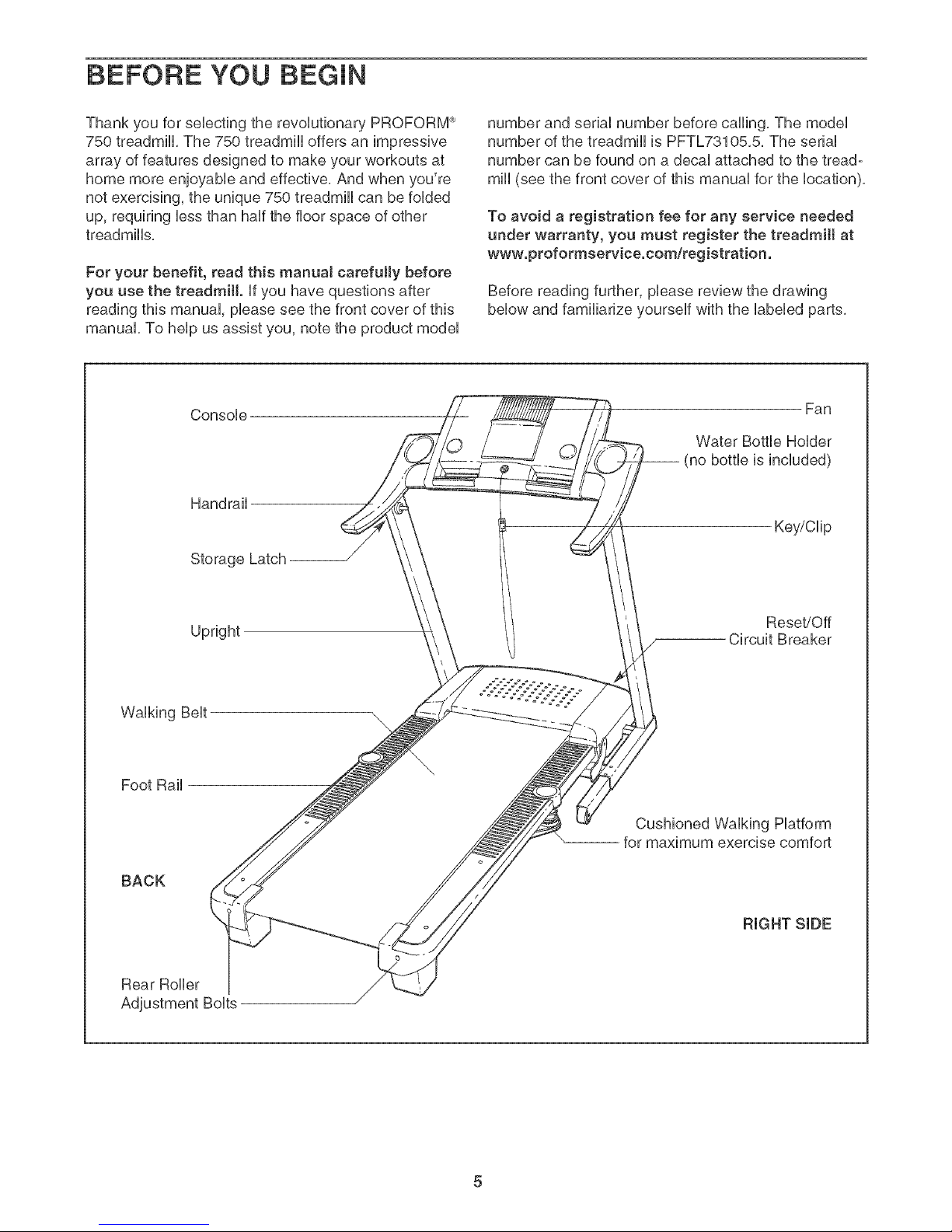
Before reading further, please review the drawing
below and familiarize yourself with the labeled parts,
Fan
Water Bottle Holder
(no bottle is included)
Key/Clip
Upright
Walking Belt
Foot Rail
BACK
Rear Roller
Reset/Off
Circuit Breaker
Cushioned Walking Platform
for maximum exercise comfort
RIGHT SIDE
Page 6
To hire an authorized service technician to assemble the trearfmilt, call totJ-free 1-800-445-2480.
Assembty requires two persons. Set the treadmill in a cbared area and remove all packing materials, Do not
dispose of the packing materials until assembly is compbted, Note: The underside of the treadmill walking belt is
coated with high-performance lubrbant, During shipping, a small amount of lubrbant may be transferred to the
top of the walking belt or the shipping carton, This is a normal condition and does not affect treadmill perfor-
mance, If there is lubricant on top of the walking belt, simply wipe off the lubricant with a soft cloth and a mild,
non-abrasive cleaner,
Assembty requires the included allen wrench ]1 and your own philtips screwdriver (with
E
a shaft at teast 8" tong} and wire cutters
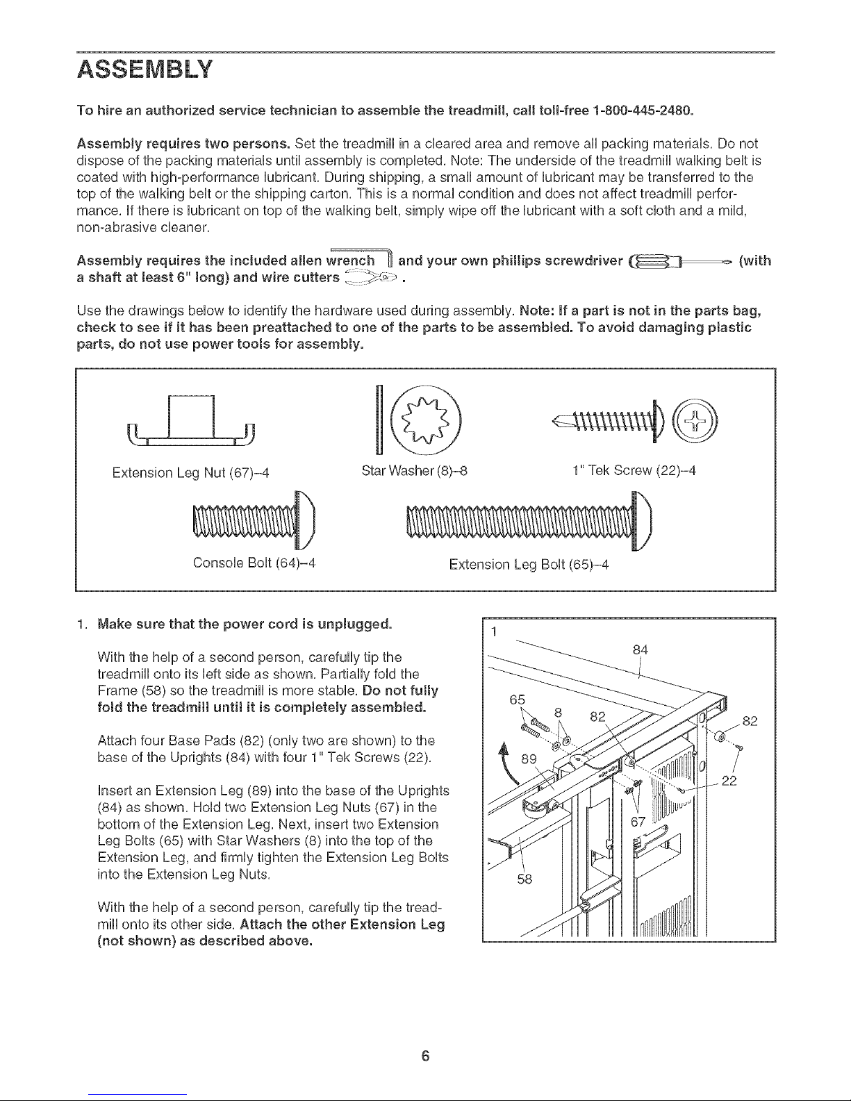
Use the drawings below to identify the hardware used during assembly, Note: if a part is not in the parts bag,
check to see if it has been preattached to one of the parts to be assemblerf. To avoid damaging ptastic
parts, do not use power toots for assembly.
Extension Leg Nut (67)-4
Star Washer (8)-8 1" Tek Screw (22)-4
Console Bolt (64)-4
1, Make sure that the power cord is unpluggerf.
With the help of a second person, carefully tip the
treadmill onto its left side as shown, Partially fold the
Frame (58) so the treadmill is more stable, Do not fully
fotrf the trearfmilt until it is completely assemblerf.
Attach four Base Pads (82) (only two are shown) to the
base of the Uprights (84) with four 1" Tek Screws (22),
insert an Extension Leg (89) into the base of the Uprights
(84) as shown, Hold two Extension Leg Nuts (67) in the
bottom of the Extension Leg, Next, insert two Extension
Leg Bolts (65) with Star Washers (8) into the top of the
Extension Leg, and firmly tighten the Extension Leg Bolts
into the Extension Leg Nuts,
Extension Leg Bolt (65)-4
84
65
82
58
With the help of a second person, carefully tip the tread-
mill onto its other side, Attach the other Extension Leg
(not shown} as described above.
Page 7
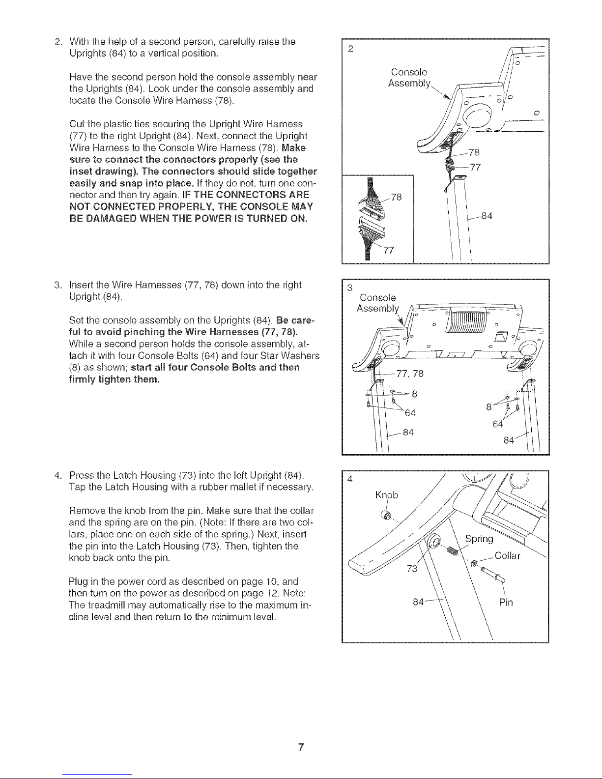
2, Withthehelpofasecondperson,carefullyraisethe
Uprights(84)toaverticalposition,
Havethesecondpersonholdtheconsoleassemblynear
theUprights(84),Lookundertheconsoleassemblyand
locatetheConsoleWireHarness(78),
CuttheplastictiessecuringtheUprightWireHarness
(77)totherightUpright(84),Next,connecttheUpright
WireHarnesstotheConsoleWireHarness(78),Make
suretoconnecttheconnectorsproperly(seethe
insetdrawing).TheconnectorsshouldsJidetogether
easity and snap into place, if they do not, turn one con-
nector and then try again, mFTHE CONNECTORS ARE
NOT CONNECTED PROPERLY, THE CONSOLE MAY
BE DAMAGED WHEN THE POWER mSTURNED ON.
Console
Assembly.
78
"" 77
insert the Wire Harnesses (77, 78) down into the right
Upright (84),
Set the console assembly on the Uprights (84). Be care-
fui to avoid pinching the Wire Harnesses (77, 78).
While a second person holds the console assembly, at-
tach it with four Console Bolts (64) and four Star Washers
(8) as shown; start aH four Console BoJts and then
firmly tighten them.
Press the Latch Housing (73) into the left Upright (84).
Tap the Latch Housing with a rubber mallet if necessary.
Remove the knob from the pin, Make sure that the collar
and the spring are on the pin, (Note: if there are two col-
lars, place one on each side of the spring,) Next, insert
the pin into the Latch Housing (73), Then, tighten the
knob back onto the pin,
3
Console
t--84 84_I
Knob
Hug in the power cord as described on page 10, and
then turn on the power as described on page 12, Note:
The treadmill may automatically rise to the maximum in-
cline level and then return to the minimum level,
Pin
Page 8
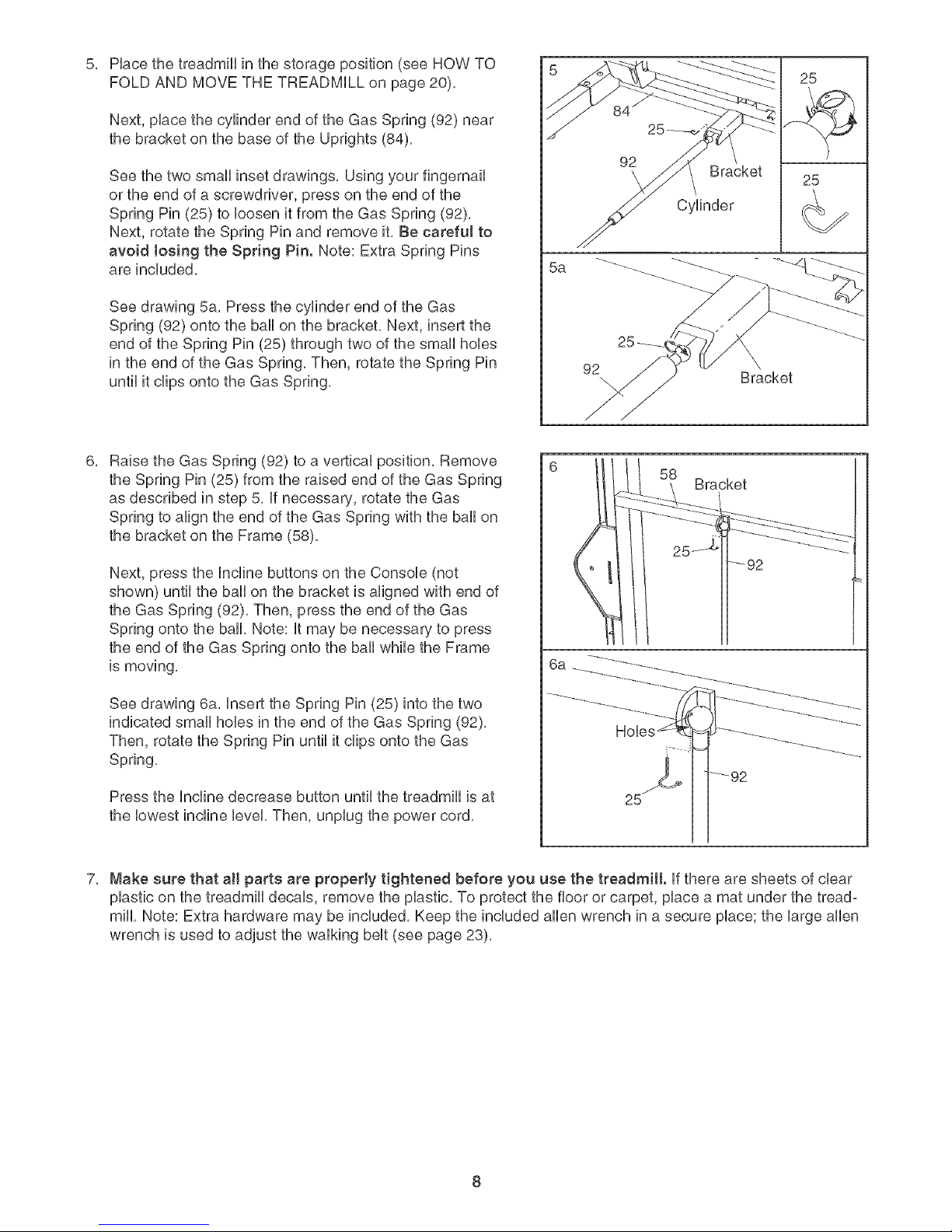
Hace the treadmHUin the storage position (see HOW TO
FOLD AND MOVE THE TREADMILL on page 20),
Next, pUacethe cylinder end of the Gas Spring (92) near
the bracket on the base of the Uprights (84),
See the two small inset drawings, Using your fingernail
or the end of a screwdriver, press on the end of the
Spring Pin (25) to loosen it from the Gas Spring (92),
Next, rotate the Spring Pin and remove it, Be ¢arefuJ to
avoid Josing the Spring Pin. Note: Extra Spring Pins
are included,
See drawing 5a, Press the cylinder end of the Gas
Spring (92) onto the ball on the bracket, Next, insert the
end of the Spring Pin (25) through two of the small hobs
in the end of the Gas Spring, Then, rotate the Spring Pin
until it clips onto the Gas Spring,
Raise the Gas Spring (92) to a vertical position, Remove
the Spring Pin (25) from the raised end of the Gas Spring
as described in step 5, if necessary, rotate the Gas
Spring to align the end of the Gas Spring with the ball on
the bracket on the Frame (58),
Cylinder _._
Bracket
Next, press the Incline buttons on the Console (not
shown) until the ball on the bracket is aligned with end of
the Gas Spring (92), Then, press the end of the Gas
Spring onto the ball, Note: it may be necessary to press
the end of the Gas Spring onto the ball while the Frame
is moving,
6a
See drawing 6a, insert the Spring Pin (25) into the two
indicated small hobs in the end of the Gas Spring (92),
Then, rotate the Spring Pin until it clips onto the Gas
Spring,
Press the Incline decrease button until the treadmill is at
the lowest incline level, Then, unplug the power cord,
7, Make sure that aH parts are properly tightened before you use the treadmill, if there are sheets of clear
plastic on the treadmill decals, remove the plastic, To protect the floor or carpet, place a mat under the tread°
mill, Note: Extra hardware may be included, Keep the included allen wrench in a secure place; the large allen
wrench is used to adjust the walking belt (see page 23),
8
Page 9
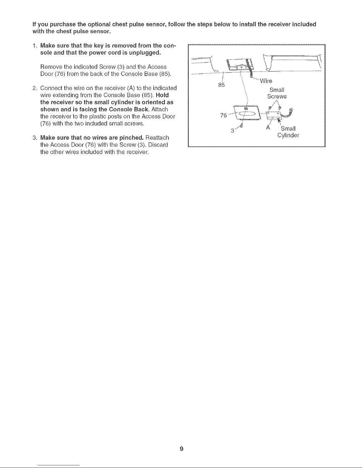
if you purchase the optional chest pulse sensor, follow the steps below to install the receiver included
with the chest pulse sensor.
1, Make sure that the key is removed from the con-
sole and that the power cord is unplugged.
Remove the indicated Screw (3) and the Access
Door (76) from the back of the Console Base (85),
2, Connect the wire on the receiver (A) to the indicated
wire extending from the ConsoUe Base (85), HoJd
the receiver so the small cylinder is oriented as
shown and is facing the Console Back. Attach
the receiver to the pUasticposts on the Access Door
(76) with the two included small screws,
3, Make sure that no wires are pinched. Reattach
the Access Door (76) with the Screw (3), Discard
the other wires included with the receiver,
Small
Screws
3 _ A Small
Cylinder
Page 10

OPERATmON AND ADJUSTMENT
THE PRE-LUBRICATED WALKING BELT
Your treadmHUfeatures a waUkingbeUtcoated with high°
performance Uubrbant. IMPORTANT: Never apply sil-
icone spray or other substances to the waJking
beJt or the walking platform. Such substances will
deteriorate the walking belt and cause excessive
wear.
HOW TO PLUG IN THE POWER CORD
DANG ER: Improperconnection
of the equipment-grounding conductor can
resuJt in an increased risk of eJectric shock.
Check with a qualified eJectrician or service-
man if you are in doubt as to whether the
product is properly grounded. Do not modify
the plug p rovided with the productJif it wHJ
not fit the outlet, have a proper ouNet
installed by a quaJified eJectrician.
Your treadmill, like any other type of sophisticated
electronic equipment, can be seriously damaged by
sudden voltage changes in your home's power.
Voltage surges, spikes, and noise interference can
result from weather conditions or from other appliances
being turned on or off. To decrease the possibility of
your treadmill being damaged, always use a surge
suppressor with your treadmill (see drawing 1 at
the right}. To purchase a surge suppressor, see
your JocaJPROFORM deaJer or call the toll-free
teJephone number on the front cover of this man-
ual and order part number 146148, or see your JocaJ
electronics store.
tric shock. This product is equipped with a cord having
an equipment-grounding conductor and a grounding
plug. Plug the power cord into a surge suppressor,
and pJug the surge suppressor into an appropriate
outlet that is properJy installed and grounded in
accordance with aH JocaJ codes and ordinances.
Important: The treadmill is not compatible with
GFOl-equipped ouNets.
This product is for use on a nominal 120-volt circuit,
and has a grounding plug that looks like the plug illus-
trated in drawing 1 below. A temporary adapter that
looks like the adapter illustrated in drawing 2 may be
used to connect the surge suppressor to a 2-pole
receptacle as shown in drawing 2 if a properly
grounded outlet is not available.
-Grounded Outlet Box
I_..l _ Surge Suppressor
Fitl i', Ground,rigP,n
t
_rounded Outlet Grounding Plug""_
_rounded Outlet Box
Adapter
Surge Suppressor
Use only a single-outlet surge suppressor that is
UL 1449 Jisted as a transient voltage surge sup-
pressor (TVSS}. The surge suppressor must have a
UL suppressed vottage rating of 400 volts or tess
and a minimum surge dissipation of 450 joules.
The surge suppressor must be electrically rated for
120 volts AC and 15 amps. There must be a moni-
toring Hght on the surge suppressor to indicate
whether it is functioning properly. Failure to use a
properJy functioning surge suppressor could resuJt
in damage to the controt system of the treadmill. If
the control system is damaged, the waJking belt
may change speed, acceJerate or stop unexpect-
edly, which may result in a fail and serious injury.
This product must be grounded, if it should maifunc°
tion or break down, grounding provides a path of least
resistance for electric current to reduce the risk of ebc°
The temporary adapter should be used only until a
properly grounded outlet (drawing 1) can be installed
by a qualified electrician.
The green-colored rigid ear, lug, or the like extending
from the adapter must be connected to a permanent
ground such as a properly grounded outlet box cover.
Whenever the adapter is used it must be held in place
by a metal screw. Some 2-poJe receptacle outJet box
covers are not grounded. Contact a qualified elec-
trician to determine if the outlet box cover is
grounded before using an adapter.
10
Page 11

........10
_,_L,_ S
Matrix
FEATURES OF THE CONSOLE
The treadmHUconsoUe offers an impressive array of
features designed to make your workouts more effec-
tive, When the manuaU mode of the consoUe is seo
Uected,you can change the speed and incline of the
treadmHUwith the touch of a button, As you exercise,
the consoUe wHUdispUaycontinuous exercise feedback,
You can even measure your heart rate using the hand-
grip puUsesensor or the optionaU chest puUsesensor
(see page 19),
Priority DispUay
PROGRAMS
'4.2,.....
D sp ay
The console also offers two pulse programs that con°
trol the speed and incline of the treadmill to keep your
heart rate near target heart rate settings during your
workouts, Note: The pulse programs require the use of
the optional chest pulse sensor,
To use the manuaJ mode of the consoJe, follow the
steps beginning on page 12, To use a personal
trainer program, see page 14, To create and use a
custom program, see pages 15 and 16, To use a
pulse program, see page 17,
Unaddition, the consoUe features six personaU trainer
programs, Each program automatically controUsthe
speed and incline of the treadmill as it guides you
through an effective workout, You can even create
your own custom programs and store them in memory
for future use,
Note: If there is a sheet of clear plastic on the face
of the console, remove the plastic. To prevent dam-
age to the walking platform, aJways wear clean
shoes while using the treadmill.
11
Page 12

HOW TO TURN ON THE POWER
Hug in the power cord
(see page 10), Next, locate
the reset/off circuit breaker
on the treadmill near the
power cord, Make sure that
the circuit breaker is in the
reset position,
speed setting wiii change by 0,1 mph; if a button
is held down, the speed setting will change in in-
crements of 0,5 mph, Note: After the buttons are
pressed, it may take a moment for the walking belt
to reach the selected speed setting,
Position
Reset
if one of the ten numbered speed buttons is
pressed, the walking belt wiii gradually increase in
speed until it reaches the selected speed setting,
Next, stand on the foot rails of the treadmill, Find the
clip attached to the key (see the drawing on page 11),
and slide the clip onto the waistband of your clothes,
Then, insert the key into the console, After a moment,
the matrix and the display wiii light, Important: In an
emergency situation, the key can be pulled from
the consoJe, causing the walking belt to sJow to a
stop. Test the clip by carefully taking a few steps
backward; if the key is not pulled from the consoJe,
adjust the position of the clip.
NOW TO USE THE MANUAL MODE
Insert the key into the console.
See HOW TO TURN ON THE POWER above,
Select the manuaJ mode.
Each time the key is in-
serted, the manual
mode wiii be selected,
if a program has been
selected, reselec_tthe
manual mode by
pressing any program
button twice; a track
wiii appear in the
matrix,
0 .1
To stop the walking belt, press the Stop button, To
restart the walking belt, press the Start button, the
Speed + button, or one of the ten numbered but-
tons,
Note: The first time the treadmill is used, observe
the alignment of the walking belt, and center the
walking belt if necessary (see page 23),
Change the incline of the treadmill as desired.
To change the incline of the treadmill, press the
Incline increase and decrease buttons, Each time
a button is pressed, the incline wiii change by
0,5%, Note: After the buttons are pressed, it may
take a moment for the treadmill to reach the se-
lected incline setting,
Follow your progress with the matrix and the
display.
When the manual mode
is selected, the matrix
wiii show a track repre-
senting 1/4 mile, As you
walk or run on the tread°
mill, the indicators
around the track wiii ap-
pear in succession until
the entire track appears,
The track wiii then disappear and the indicators wiii
again begin to appear in succession,
[] []
Start the waJking belt.
To start the walking belt, press the Start button,
the Speed + button, or one of the ten numbered
speed buttons,
if the Start button or the Speed + button is
pressed, the walking belt wiii begin to move at 1
mph, As you exercise, change the speed of the
walking belt as desired by pressing the Speed +
and - buttons, Each time a button is pressed, the
The lower left corner of
the display wiii show the
calories you have
burned and the incline
level of the treadmill,
When you use the handgrip pulse sensor or the
optional chest pulse sensor, the lower left corner of
the display will also show your heart rate,
12
Page 13

The lower right corner I _'_"
Io_: LTJ_;J
the distance that you _N_ £2Tt
have walked or run, the OoUsPEED
of the display wiii show }-s. _,._ICC D_ST.
elapsed time, your
pace (in minutes per
mile), and the speed of the walking belt. Note:
When a program is selected (except for a custom
program or pulse program 9), the lower right cor-
ner of the display will show the time remaining in
the program instead of the elapsed time.
The center of the dis-
play is the priority dis-
play. Press the Priority
Display button repeat°
edly until the priority
display shows the in-
formation that you want to view. Note: While infor-
mation is displayed in the priority display, the same
information wiii not be displayed in the lower left or
Note: The console can display speed and dis-
tance in either miles or kilometers. A "Km/H" will
appear in the right side of the display when the
console is displaying speed and distance in kilo-
meters. To change the unit of measurement, see
THE iNFORMATiON MODE/DEMO MODE on
page 19. Note: For simplicity, aHinstructions in
this section refer to miles.
To reset the display, press the Stop button, re-
move the key, and then reinsert the key.
Measure your heart rate if desired.
Note: if you use the handgrip pulse sensor and
the optional chest pulse sensor at the same time,
the console will not display your heart rate accu-
rately.
To use the handgrip pulse sensor, first remove the
sheets of clear plastic from the metal contacts, in
addition, make
sure that your
hands are
clean. Next,
stand on the
foot rails and
hold the metal Contacts
contacts--
avoid moving
your hands. When your pulse is detected, the
heart symbol in the lower left corner of the display
will appear, one or two dashes will appear, and
then your heart rate will be shown. For the most
accurate heart rate reading, continue to hoM
the contacts for about 15 seconds.
Turn on the fan if desired.
To turn on the fan, press the Fan button. To turn
on the fan at high speed, press the button a sec-
ond time. To turn off the fan, press the button a
third time. Note: if the fan is left on when the walk-
ing belt is stopped, the fan will automatically turn
off after a few minutes.
When you are finished exercising, remove the
key from the console.
Step onto the foot rails, press the Stop button, and
adjust the incline of the treadmill to the lowest
setting. The incline must be at the lowest setting
when the treadmill is fotded to the storage posi-
tion or the treadmill will be damaged. Next, re-
move the key from the console and put it in a se-
cure place. Note: If the display remains tit after
the key is removed, the consoJe is in the
"demo" mode. See page 19 and turn off the
demo mode.
When you are finished using the treadmill,
switch the reset/off circuit breaker to the "off"
position and unptug the power cord.
13
Page 14

HOW TO USE A PERSONAL TRAINER PROGRAM
settings for the next several segments wiii be
shown in the columns to the right,
Insert the key into the console.
See HOW TO TURN ON THE POWER on page
12,
Select one of the personal trainer programs.
To select a personal trainer program, press one of
the six personal trainer program buttons; "P1,"
"P2," "P3," "P4," "P5," or "P6" will appear in the pri-
ority display for a few seconds,
A few seconds after a personal trainer program us
selected, the maximum incline setting of the pro-
gram and the maximum speed setting of the pro-
gram will flash in the display for a few seconds,
The display will also show how long the program
will last, A profile of the speed settings of the pro-
gram will scroll across the matrix,
Press the Start button or the Speed + button to
start the program.
A moment after the button is pressed, the tread-
mill will automatically adjust to the first speed and
incline settings of the program, Hold the handrails
and begin walking,
Each program is divided into 30 one-minute seg-
ments, One speed setting and one incline setting
are programmed for each segment, Note: The
same speed setting and/or incline setting may be
programmed for two or more consecutive seg-
ments,
The speed setting for
the first segment wiii
be shown in the flash-
Segment
ing Current Segment
column of the matrix,
Current
(The incline settings
are not shown in the
--1
PROGRAM
matrix,) The speed
When only three seconds remain in the first seg-
ment of the program, both the Current Segment
column and the column to the right will flash and a
series of tones will sound, if the speed and/or in-
cline of the treadmill is about to change, the speed
setting and/or the incline setting wiii flash in the
display to alert you,
When the first segment is completed, allepeed
ee4@7_5"v/i//move one coidmn to the ie,_t,The
speed setting for the second segment will then be
shown in the flashing Current Segment column,
and the treadmill will automatically adjust to the
speed and incline settings for the second seg-
ment. Note: if all seven of the indicators in the
Current Segment column are fit, the epeed'ee4_i_'9':¢
maymove downwafdso that only the highest indi-
cators appear in the matrix,
The program will continue in this way until the
speed setting for the last segment is shown in the
Current Segment column and the last segment
ends, The walking belt wiii then slow to a stop,
if the speed or incline setting for the current seg-
ment is too high or too low, you can manually
override the setting by pressing the Speed or
Incline buttons, Every few times a Speed button is
pressed, an additional indicator wiii appear or dis-
appear in the Current Segment column; if any of
the columns to the right of the Current Segment
column have the same number of lit indicators as
the Current Segment column, an additional indica-
tor may appear or disappear in those columns as
weft, Important: When the current segment of
the program ends, the treadmill will automati-
cally adjust to the speed and incline settings
for the next segment.
To stop the program at any time, press the Stop
button, To restart the program, press the Start but-
ton or the Speed + button, The walking belt will
begin to move at 1 mph, When the next segment
of the program begins, the treadmill will automati-
cally adjust to the speed and incline settings for the
next segment,
Follow your progress with the matrix and the
display.
See step 5 on page 12,
14
Page 15

Measure your heart rate if desired.
See step 6 on page 13,
Press the Start button or the Speed increase
button and program the desired speed and in-
cline settings.
Turn on the fan if desired.
See step 7 on page 13,
When you are finished exercising, remove the
key from the consote.
When the program ends, make sure that the in-
cline of the treadmil! is at the towest setting.
Next, remove the key from the consob and put it in
a safe pUace,Note: If the display remains lit
after the key is removed, the console is in the
"demo" mode. See page 19 and turn off the
demo mode.
When you are finished using the treadmill,
switch the reset/off circuit breaker to the "off"
position and unplug the power cord.
NOW TO CREATE A CUSTOM PROGRAM
Insert the key into the consote.
See HOW TO TURN ON THE POWER on page
12,
Select one of the custom programs.
To sebct a custom program, press either of the
custom program buttons; "P7" or "P8" wHUappear
in the priority display for a few seconds,
mm
PROSt_AM
A moment after the button is pressed, the walking
belt will begin to move, Hold the handrails and
begin walking,
Refer to the matrix, Each custom program is di-
vided into one-minute segments, One speed set-
ting and one incline setting can be programmed
for each segment, The
speed setting for the
first segment wiii be
shown in the flashing
Segment
Current Segment cop
umn of the matrix, (The
incline settings are not
shown in the matrix,) To
Current T-
PROGRA_
program a speed set-
ting and an incline set-
ting for the first segment, simply adjust the speed
and incline of the treadmill as desired by pressing
the Speed and incline buttons, Every few times a
Speed button is pressed, an additional indicator
will appear or disappear in the Current Segment
column,
When the first segment of the program ends, a se=
ries of tones wiii sound and the current speed set-
ting and the current incline setting will be saved in
memory, The three co/umne of/ho'/catore wi//then
move one co/umn to the/e/,,_ and the speed set-
ting for the second segment will be shown in the
flashing Current Segment column, Program a
speed setting and an incline setting for the second
segment as described above,
Continue programming speed and incline settings
for as many segments as desired; custom pro=
grams can have up to forty segments, When you
are finished with your workout, press the Stop but-
ton twice, The speed and incline settings that you
have programmed and the number of segments
that you have programmed wiii then be saved in
memory,
Note: If the custom program has not yet been
defined, three cotumns of indicators will scroll
across the matrix. If more than three columns
of indicators appear, see NOW TO USE A CUS-
TOM PROGRAM on page 16.
When you are finished exercising, remove the
key from the consote.
See step 7 on this page,
15
Page 16

HOW TO USE A CUSTOM PROGRAM
in the matrix,) The speed settings for the next four
segments are shown in the columns to the right,
mnsertthe key into the console.
See HOW TO TURN ON THE POWER on page
12,
Select one of the custom programs.
To select a custom program, press either of the
custom program buttons; "P7" or "P8" wHiappear
in the priority dispiay for a few seconds,
A few seconds after a custom program is se-
lected, the maximum
gram and the maximum speed setting of the pro-
gram wHi flash in the dispiay for a few seconds,
The dispiay wHi aiso show how iong the program
wHiHast,A profile of the speed settings of the pro-
gram wHi scroli across the matrix,
Note: If only three columns of indicators scroll
across the matrix, see HOW TO CREATE A
CUSTOM PROGRAM on page 15.
When only three seconds remain in the first seg-
ment of the program, both the Current Segment
column and the column to the right will flash, a
series of tones will sound, and the speed setting
and the incline setting wiii flash in the display,
When the first segment ends, aiispeed'seLff/7ds
wiii mo_'e,one coidmn to tA_e/eft, The speed setting
for the second segment will then be shown in the
flashing Current Segment column, and the tread-
mill will automatically adjust to the second speed
and incline settings that you programmed previ-
ously,
The program will continue in this way until the
speed setting for the last segment is shown in the
Current Segment column and the last segment
ends, The walking belt wiii then slow to a stop,
if desired, you can redefine to the program while
using it, To change the speed or incline setting
for the current segment, simply press the Speed
or Incline buttons, When the current segment ends,
the new setting will be saved in memory, To in-
crease the length of the program, first wait until
the program is completed, Then, press the Start but-
ton and program speed and incline settings for as
many additional segments as desired, When you
have added as many segments as desired, press
the Stop button twice, To decrease the Jength of
the program, press the Stop button twice at any
time before the program is completed,
Press the Start button or the Speed increase
button to start the program.
A moment after the button is pressed, the tread-
mill will automatically adjust to the first speed and
incline settings that you programmed previously,
Hold the handrails and begin walking,
Each custom program
is divided into several
One speed setting and
one
programmed for each
segment, (The same
speed setting and/or
incline setting may be
programmed for two or more consecutive seg-
ments,) The speed setting for the first segment wiii
be shown in the flashing Current Segment column
of the matrix, (The incline settings are not shown
To stop the program at any time, press the Stop
button, To restart the program, press the Start but-
ton or the Speed increase button,
Fottow your progress with the matrix and the
display.
See step 5 on page 12,
Measure your heart rate if desired.
See step 6 on page 13,
Turn on the fan if desired.
See step 7 on page 13,
When you are finished exercising, remove the
key from the consote.
See step 7 on page 15,
16
Page 17

HOWT0 USE A PULSE PROGRAM
CA UTION: ifyouhoveheartprob-
lems,or if you are over 60 years of age and
have been hsactive, do not use the pulse pro-
grams, mfyou are taking medication regularly,
consult your physician to find whether the
medication will affect your exercise heart rate.
Enter a target heart rate setting.
If puJse program 9 is
selected, the target
heart rate setting for the
entire program will flash
in the display, If de-
sired, press the Heart
Rate increase and de-
crease buttons to change the target heart rate set-
ting (see EXERCISE INTENSITY on page 24}.
Follow the steps bebw to use a pube program,
Put on the optional chest putse sensor.
You must wear the optional chest pulse sensor
to use a pulse program.
Insert the key into the consote.
See HOW TO TURN ON THE POWER on
page 12,
Select one of the putse programs.
To sebct a pube program, press either of the
puUseprogram buttons; "P9" or "PIO" wHUappear in
the priority display for a few seconds,
if pulse program 10 is selected, the maximum
target heart rate setting of the program will flash in
the display, If desired, press the Heart Rate in-
crease and decrease buttons to change the maxi-
mum target heart rate setting (see EXERCISE IN-
TENSITY on page 24}. Note: If the maximum tar-
get heart rate setting is changed, the intensity
level of the entire program will change,
Press the Start button or the Speed + button to
start the program.
A moment after the button is pressed, the tread-
mill will automatically adjust to the first speed and
incline settings of the program, Held the handrails
and begin walking,
Pulse program 9 is divided into 40 one-minute
segments, The same target heart rate setting is
programmed for all segments, (For a shorter
workout, simply stop the program before it ends,)
Pulse program 10 is divided into 30 one-minute
segments, One target heart rate setting is pro-
grammed for each segment, Note: The same tar-
get heart rate setting may be programmed for two
or more consecutive segments,
If pulse program g is selected, a pulse symbol
wii[ scroll across the matrix (see the drawing
above),
If puJse program !0
isseJected, a profile
of the target heart rate
settings of the pro-
gram will scroll across
the matrix,
If pulse program 10 is
selected, the target
heart rate setting for
the first segment will be
shown in the flashing
Current Segment col-
umn of the matrix, The
target heart rate set-
tings for the next sev-
eral segments wiii be shown in the columns to the
right, When only three seconds remain in the first
segment of the program, both the Current
Segment column and the column to the right will
flash and a series of tones will sound,
17
Page 18

When the first segment ends, allta,%etheaftrate
set,@gs wiiimove one coiumn /othe/eft.The tar=
get heart rate setting for the second segment wHU
then be shown in the flashing Current Segment
coUumn,
During both pulse programs, the console wiii reg°
ularly compare your heart rate to the target heart
rate setting, if your heart rate is too far below or
above the target heart rate setting for the current
segment, the speed of the walking belt will auto°
matically increase or decrease to bring your heart
rate closer to the target heart rate setting,
To stop the program at any time, press the Stop
button, To restart the program, press the Start but-
ton or the Speed + button, The walking belt will
begin to move at 1 mph, When the console com-
pares your heart rate to the target heart rate set-
ting, the speed and/or incline of the treadmill may
automatically change to bring your heart rate
closer to the target heart rate setting,
Follow your progress with the matrix and the
display.
See step 5 on page 12,
if the speed or incline setting is too high or too low
at any time during the program, you can adjust the
setting with the Speed or Incline buttons, However,
when the console compares your heart rate to the
target heart rate setting, the speed of the treadmill
may automatically change to bring your heart rate
closer to the target heart rate setting,
if your pulse is not detected during the program,
the letters "PLS" wiii flash in the display and the
speed of the treadmill may automatically
decrease, if this occurs, see the instructions in-
cluded with the optional chest pulse sensor,
Turn on the fan if desired.
See step 7 on page 13,
When you are finished exercising, remove the
key from the console.
See step 7 on page 15,
18
Page 19

THE INFORMATION MODE/DEMO MODE
The consob features an information mode that keeps
track of the totaUnumber of hours that the treadmHUhas
been operated and the totaUdistance that the waUking
beUthas moved. The information mode aUsoallows you
to sebct miles or kilometers as the unit of measure-
ment and to turn on and turn off the demo mode.
To sebct the information mode, hoUddown the Stop
button while inserting the key into the consob, and
then rebase the Stop button. When the information
mode is sebcted, the following information wHUbe dis-
pUayed:
pUaywHUshow the
totaUnumber of
miles (or kilome-
ters) that the
walking belt has
moved. The
lower right corner
of the display will
show the total number of hours that the treadmill has
been operated. An "E" for English miles or an "M" for
metric kilometers will appear in the lower left corner of
the display. Press the Speed + button to change the
unit of measurement if desired.
OG 23
IMPORTANT: If a
"d" appears in the
lower left corner
of the display, the
console is in the
"demo" mode.
This mode is in-
tended to be used
only when a
treadmill is displayed in a store. When the console is in
the demo mode, the power cord can be plugged in, the
key can be removed from the console, and the indica-
tors in the display will automatically appear in a preset
sequence; the buttons on the console will not operate. If
a "d" appears when the information mode is se-
lected, press the Speed - button so "d" disappears.
To exit the information mode, remove the key from the
console.
THE OPTIONAL CHESTPULSESENSOR
The optional chest pulse sensor offers hands-free op-
eration and enables you to use the console's pulse
programs. To purchase the optionaJ chest puJse
sensor, call the toll-free telephone number on the
front cover of this manual
d ;2 4
t'- t"_
19
Page 20

HOW TO FOLD AND MOVE THE TREADMILL
HOW TO FOLD THE TREADMmLL FOR STORAGE
Before folding the treadmill, adjust the incline to the
lowest position, mftMs is not done, the treadmill may be per-
manently damaged. Next, unplug the power cord. CAUTmON:
You must be able to safely lift 45 pounds (20 kg) to raise,
tower, or move the treadmill.
1, Hold the metal frame firmly in the location shown by the
arrow at the right. CAUTmON: To decrease the possibility
of injury, do not lift the frame by the plastic foot raits.
Make sure you bend your Jegs and keep your back
straight. As you raise the frame, make sure to Hft with
your Jegs rather than your back. Raise the frame about
halfway to the vertical position,
2, Move your right hand to the position shown and hold the
treadmill firmly, Using your left hand, pull the latch knob to
the left and hold it, Raise the frame until the catch is past the
latch pin, Slowly release the latch knob, Make sure that the
catch is securely held by the tatch pin,
Frame
To protect the floor or carpet from damage, place a mat
under the treadmill. Keep the treadmill out of direct sun-
tight. Do not leave the treadmill in the storage position in
temperatures above 85 ° Fahrenheit.
HOW TO MOVE THE TREADMILL
Before moving the treadmill, convert the treadmill to the storage
position as described above, Make sure that the catch is se-
curely held by the tatch pin.
1, Hold the upper ends of the handrails, Place one foot against
one of the wheels,
2, Tilt the treadmill back until it rolls freely on the front wheels,
Carefully move the treadmill to the desired location, To re-
duce the risk of injury, use extreme caution while mov-
ing the treadmill. Do not move the treadmill over an un-
even surface.
3, Place one foot against one of the wheels, and carefully lower
the treadmill until it is resting in the storage position,
_gaged
Base
2O
Page 21

HOW TO LOWER THE TREADMmLL FOR USE
1, HoUdthe upper end of the treadmHUwith your right hand, Pull
the Uatchknob to the Ueftand hoUdit, Pivot the treadmHUdown
until the catch is past the Uatchpin,
2, HoJd the metal frame firmly with both hands, and Uowerthe
treadmHUto the floor, CAUTION: To decrease the possibility
of injury, do not lower the treadmill by gdpping only the
plastic foot rails. Do not drop the treadmill frame to the
floor. Be sure to bend your legs and keep your back
straight.
\
Frame
21
Page 22

TROUBLESHOOTmNG
Most treadmill tsroblems can be sotvod by following the steps below. Find the symptom that applies, and
fottow the stops tistod, mffurther assistance is needed, please see the front covor of this manual.
PROBLEM: The power doos not turn on
SOLUTmON: a,
PROBLEM: The power turns off during use
SOLUTION: a. Check the reset/off circuit breaker (see the drawing above), if the circuit breaker has tripped, wait
Make sure that the power cord is plugged into a surge suppressor, and that the surge suppressor
is plugged into a properly grounded outlet (see page 10). Use only a single-outlet surge suppres-
sor that meets all of the specifications described on page 10. important: The treadmill is not com-
patible with GFCI-equipped outlets.
b. After the power cord has been plugged in, make sure that the key is inserted into the console.
Check the reset/off circuit breaker located on the
C,
treadmill frame near the power cord. if the switch
protrudes as shown, the circuit breaker has
tripped. To reset the circuit breaker, wait for five
minutes, and then press the switch back in.
for five minutes and then press the switch back in.
b. Make sure that the power cord is plugged in. if the power cord is plugged in, unplug it, wait for
five minutes, and then plug it back in.
c. Remove the key from the console. Reinsert the key into the console.
d. if the treadmill still will not run, see the front cover of this manual.
Tripped
Reset
PROBLEM: The incline of the treadmill doos not chango correctly
SOLUTmON: a, With the key in the console, pross one of the Incline buttons, While the incline is changing, re-
move the key. After a few seconds, re-insert the key. The treadmill will automatically rise to the
maximum incline level and then return to the minimum level. This will recalibrate the incline system.
PROBLEM: The display of the consoto does not function property
SOLUTION: a, Remove the key from the console and UNPLUG THE
POWER CORD. With the help of a second person,
carefully tip the Uprights (84) down as shown. Next,
remove the three Screws (3) and the three Hood
Screws (7). Note: A phillips screwdriver with a shaft at
bast 5" long is required.
84
22
Page 23

With the heUpof a second person, carefully raise the
Uprights (84) to the position shown, Carefully pivot the
Hood (41) off,
41
Locate the Reed Switch (63) and the Magnet (46) on
the left side of the Pulley (47), Turn the Pulley until the
Magnet is aligned with the Reed Switch, Make sure
Top
View
that the gap between the Magnet and the Reed
Switch is about 1/8". if necessary, loosen the Screw
(3), move the Reed Switch slightly, and then retighten
the Screw, Reattach the Hood (not shown), and run
the treadmill for a few minutes to check for a correct
speed reading,
PROBLEM: The walking belt slows when walked on
SOLUTION: a, Use only a single-outlet surge suppressor that meets all of the specifications described on page 10,
b,
if the walking belt is overtightened, treadmill perfor-
mance may decrease and the walking belt may be-
come damaged, Remove the key and UNPLUG THE
POWER CORD, Using the allen wrench, turn both
rear roller bolts counterclockwise, 1/4 of a turn, When
the walking belt is properly tightened, you should be
able to lift each edge of the walking belt 2 to 3 inches
off the walking platform, Be careful to keep the walk-
ing belt centered, Then, plug in the power cord, insert
the key, and run the treadmill for a few minutes,
Rear Roller Bolts
Repeat until the walking belt is properly tightened,
c, if the walking belt still slows when walked on, see the front cover of this manual,
PROBLEM: The waJking belt is off-center or stips when walked on
SOLUTION: a,
If the waIMng belt is off-center, first remove the key
and UNPLUG THE POWER CORD, mfthe walking
belt has shifted to the left, use the allen wrench to
turn the bft rear roller boutcbekwbe 1/2 of a turn; if
the walking belt has shifted to the right, turn the
left bolt counterclockwise 1/2 of a turn, Be careful not
to overtighten the walking belt, Then, plug in the
power cord, insert the key, and run the treadmill for a
few minutes, Repeat until the walking belt is centered,
b,
If the walking beJt slips when waJked on, first re-
move the key and UNPLUG THE POWER CORD,
Using the allen wrench, turn both rear roller bolts
clockwise, 1/4 of a turn, When the walking belt is cor-
rectly tightened, you should be able to lift each edge
of the walking belt 2 to 3 inches off the walking plat-
form, Be careful to keep the walking belt centered,
Then, plug in the power cord, insert the key, and care°
fully walk on the treadmill for a few minutes, Repeat
until the walking belt is properly tightened,
23
Page 24

CONDiTiONiNG GUmDEUNES
WARNING: BeforebeginningtHs
or any exercise program, consult your physi°
cian. This is especially important for individu-
als over the age of 35 or individuals with pre-
existing health problems.
The pulse sensor is not a medical device.
Various factors, including your movement,
may affect the accuracy of heart rate readings.
The sensor is intended onty as an exercise aid
in determining heart rate trends in general
The following guidelines wiii help you to plan your ex=
ercise program, For more detailed exercise informa=
tion, obtain a reputable book or consult your physician,
EXERCISE iNTENSiTY
Whether your goal is to burn fat or to strengthen your
cardiovascular system, the key to achieving the
desired results is to exercise with the proper intensity,
The proper intensity level can be found by using your
heart rate as a guide, The chart below shows recom-
mended heart rates for fat burning and aerobic exercise,
is to burn fat, adjust the speed and incline of the tread-
mill until your heart rate is near the lowest number in
your training zone,
For maximum fat burning, adjust the speed and incline
of the treadmill until your heart rate is near the middle
number in your training zone,
Aerobic Exercise
if your goal is to strengthen your cardiovascular sys-
tem, your exercise must be "aerobic," Aerobic exercise
is activity that requires large amounts of oxygen for
prolonged periods of time, This increases the demand
on the heart to pump blood to the muscles, and on the
lungs to oxygenate the blood, For aerobic exercise,
adjust the speed and incline of the treadmill until your
heart rate is near the highest number in your training
zone,
WORKOUT GUiDELiNES
Each workout should include the following three parts:
A Warm-up--Start each workout with 5 to 10 minutes
of stretching and light exercise, A proper warm-up in-
creases your body temperature, heart rate and circula-
tion in preparation for exercise,
HEART RATE TRAINING ZONES
...........................AEROBUC
MAX FAT BURN 145 '}38 130 125 '}18 110 103
FAT BURN 125 120 115 110 105 95 90
Age 20 30 40 50 60 70 80
To find the proper heart rate for you, first find your age
near the bottom of the chart (ages are rounded off to
the nearest ten years), Next, find the three numbers
above your age, The three numbers define your "train-
ing zone," The lower two numbers are recommended
heart rates for fat burning; the higher number is the
recommended heart rate for aerobic exercise,
Fat Burning
To burn fat effectively, you must exercise at a relatively
low intensity level for a sustained period of time,
During the first few minutes of exercise, your body
uses easily accessible carbohydrate caioriesfor en:
ergy, Only after the first few minutes does your body
begin to use stored fat ca/cries for energy, if your goal
Training Zone Exercise--After warming up, increase
the intensity of your exercise until your heart rate is in
your training zone for 20 to 60 minutes, (During the
first few weeks of your exercise program, do not keep
your heart rate in your training zone for longer than 20
minutes,) Breathe regularly and deeply as you exer-
cise-never hold your breath,
A CooFdown--Finish each workout with 5 to 10 min-
utes of stretching to cool down, This will increase the
flexibility of your muscles and will help prevent post-
exercise problems,
EXERCISE FREQUENCY
To maintain or improve your condition, complete three
workouts each week, with at bast one day of rest be=
tween workouts, After a few months, you may com-
plete up to five workouts each week if desired, The key
to success is to make exercise a regular and enjoyable
part of your everyday life,
24
Page 25

SUGGESTED STRETCHES
The correct form for several basic stretches is shown at the right, Move slowly as you stretch--never bounce,
1. Toe Touch Stretch
Stand with your knees bent slightly and slowly bend forward from
your hips, Allow your back and shoulders to relax as you reach
down toward your toes as far as possible, Hold for 15 counts, then
relax, Repeat 3 times, Stretches: Hamstrings, back of knees and
back,
2. Hamstring Stretch
Sit with one leg extended, Bring the sob of the opposite foot toward
you and rest it against the inner thigh of your extended leg, Reach
toward your toes as far as possible, Hold for 15 counts, then relax,
Repeat 3 times for each leg, Stretches: Hamstrings, lower back and
groin,
3. Caff/Achiltes Stretch
With one leg in front of the other, reach forward and place your
hands against a wall, Keep your back leg straight and your back foot
fiat on the floor, Bend your front leg, ban forward and move your
hips toward the wall, Hold for 15 counts, then relax, Repeat 3 times
for each leg, To cause further stretching of the achilles tendons,
bend your back leg as well, Stretches: Calves, achilles tendons and
ankles,
4. Quaddceps Stretch
With one hand against a wall for balance, reach back and grasp one
foot with your other hand, Bring your heel as dose to your buttocks
as possible, Hold for 15 counts, then relax, Repeat 3 times for each
leg, Stretches: Quadrieeps and hip muscles,
5. Inner Thigh Stretch
Sit with the sobs of your feet together and your knees outward, Pull
your feet toward your groin area as far as possible, Hold for 15
counts, then relax, Repeat 3 times, Stretches: Quadriceps and hip
muscles,
25
Page 26

PART LmST Model No. PFTL73105.5 ROlO7A
To Uocate the parts Hsted beUow,see the EXPLODED DRAWUNG attached
Key No. Qty. Description
1 2 UsoUatorDeeaU 50 1
2 10 3/4" Tek Screw 51 1
3 42 Screw 52 1
4 1 Catch 53 2
5 8 Foot Rail Screw 54 1
6 4 UsoUator 55 1
7 4 UsoUatorWasher/Rear Roller Washer 56 1
8 8 Star Washer 57 1
9 2 Hatform BoUt,Back 58 1
10 2 Hatform BoUt,Front 59 1
11 4 BeUtGuide Screw 60 1
12 2 BeUtGuide 61 1
13 1 Left Handrail 62 1
14 1 Right Handrail 63 1
15 2 Frame Pivot BoUt 64 4
16 1 Left Foot Rail 65 4
17 1 Right Foot Rail 66 4
18 4 ConsoUe Frame U-nut 67 4
19 1 Static DecaU 68 2
20 1 ConsoUe Frame Support 69 1
21 1 Latch Pin AssemMy 70 2
22 4 1" Tek Screw 71 11
23 1 ConsoUe Ground Wire 72 1
24 2 Motor BoUt 73 1
25 1 Spring Pin Kit 74 2
26 1 Motor BeUt 75 3
27 1 Drive Motor 76 1
28 2 Frame Washer 77 1
29 1 U-nut 78 1
30 1 Filter Wire 79 1
31 2 Lift Frame Bolt 80 2
32 6 Locknut 81 2
33 18 1/2" Screw 82 6
34 1 Console 83 10
35 2 Fan Screw 84 1
36 1 Power Cord 85 1
37 1 Console Fan 86 1
38 1 Controller 87 2
39 1 Electronics Bracket 88 1
40 2 Rear Roller Lock Washer 89 2
41 1 Hood 90 2
42 1 Front Roller Bushing 91 2
43 1 Lift Frame 92 1
44 2 Upright Endcap 93 2
45 1 Front Roller Bolt 94 2
46 1 Magnet 95 1
47 1 Front Roller 96 1
48 1 Walking Belt 97 1
49 1 Walking Platform 98 1
Key No. Qty. Description
in the center of this manual,
Hood Cover
Rear Roller
Left Rear Endcap
Rear Roller Bolt
Right Rear Endcap
Allen Wrench
Incline Stop Bracket
Ground Wire
Frame
Belly Pan
Reed Switch Bracket
Reed Switch Clip
Front Roller Nut
Reed Switch
Console Bolt
Extension Leg Bolt
Star Washer
Extension Leg Nut
Caution Decal
Warning Decal
Platform Nut
Cable Tie
Cotter Pin, Bottom
Latch Housing
Tie Clamp
Releasable Tie
Access Door
Upright Wire Harness
Console Wire Harness
Key/Clip
Front Wheel
Wheel Bolt
Base Pad
3/4" Screw
Upright
Console Base
Cotter Pin, Top
Hair Pin Cotter Pin
Incline Motor
Extension Leg
Rear Roller Bracket
Center Isolator
Gas Spring
Isolator Bracket Cover
Isolator Bolt, Bottom
Idler Arm Pivot Bolt
Idler Arm Spacer
Idler Arm
Idler Arm Spring
26
Page 27

Key No. Qty.
Description
Key No. Qty. Description
99 1
100 1
101 1
102 1
103 5
104 1
105 2
UdbrArm Washer
UdbrArm Nut
UdbrArm Pulley
Pulley BoUt
Hood Cover Screw
Transformer
Wire Tie
106 1 Reset/Off Circuit Breaker
107 1 Consob Lens
# 1 6" Blue Wire, 2F
# 1 4" Red Wire, M/F
# 1 User's Manual
"#" indicates a non-illustrated part,
Specifications are subject to change without notice,
27
Page 28

EXPLODED DF{AWING--Modei No. PFTL73105.5 Rolo7A
I
/
To identify the parts shown on this EXPLODED DRAWING, see
the PART LIST on pages 26 and 27 of the user's manual,
Page 29

EXPLODED DF{AWING--Modei No. PFTL73105.5 RoloTA
Page 30

ORDERING REPLACEMENT PARTS
To order repUacement parts, phase see the front cover of this manuak To heUpus assist you, be prepared to
provide the following information:
* the MODEL NUMBER of the product (PFTL73105.5)
* the NAME of the product (PROFORM 750 treadmHU)
* the SERIAL NUMBER of the product (see the front cover of this manuaU)
* the KEY NUMBER and DESCRiPTiON of the part(s) (see the EXPLODED DRAWING in the center of this
manuaUand the PART LUSTon pages 26 and 27)
LIMITED WARRANTY
iCON HeaUth& Fitness, Unc.(iCON) warrants this product to be free from defects in workmanship and
material under normal use and service conditions. The drive motor is warranted for twelve (12) years
after the date of purchase. Parts and Uaborare warranted for ninety (90) days after the date of purchase.
This warranty extends onUyto the originaU purchaser, iCON's obligation under this warranty is Hmited to
replacing or repairing, at ICON's option, the product through one of its authorized service centers. All re°
pairs for which warranty claims are made must be pre°authorized by ICON. If the product is shipped to a
service center, freight charges to and from the service center will be the customer's responsibility. For in-
home service, the customer will be responsible for a minimal trip charge. This warranty does not extend
to any product or damage to a product caused by or attributable to freight damage, abuse, misuse, im-
proper or abnormal usage or repairs not provided by an ICON authorized service center; products used
for commercial or rental purposes; or products used as store display models. No other warranty beyond
that specifically set forth above is authorized by ICON.
iCON is not responsible or liable for indirect, special or consequential damages arising out of or in con-
nection with the use or performance of the product or damages with respect to any economic loss, loss
of property, loss of revenues or profits, loss of enjoyment or use, costs of removal or installation or other
consequential damages of whatsoever nature, Some states do not allow the exclusion or limitation of in-
cidental or consequential damages, Accordingly, the above limitation may not apply to you,
The warranty extended hereunder is in lieu of any and all other warranties and any implied warranties of
merchantability or fitness for a particular purpose is limited in its scope and duration to the terms set
forth herein, Some states do not allow limitations on how long an implied warranty lasts, Accordingly, the
above limitation may not apply to you,
This warranty gives you specific legal rights, You may also have other rights which vary from state to state,
ICON HEALTH & FITNESS, INC., 1500 S. 1000 W., LOGAN, UT 84321-9813
Part No, 250680 ROIO7A Printed in USA © 2007 iCON IP, Inc,
 Loading...