

Pro-Form 740 Ekg, PFEVEX2915.0 Bike Manual
Model No. PFEVEX2915.0
www.iconeurope.com
Visit our website at
Serial No.
Serial
Number
Decal
QUESTIONS?
As a manufacturer, we are committed to providing complete
customer satisfaction. If you
have questions, or if there are
missing parts, please call:
08457 089 009
Or write:
ICON Health & Fitness, Ltd.
Customer Service Department
Unit 4
Revie Road Industrial Estate
Revie Road
Beeston
Leeds, LS118JG
UK
USER'S MANUAL
email: csuk@iconeurope.com
CAUTION
Read all precautions and instructions in this manual before using
this equipment. Keep this manual
for future reference.

TABLE OF CONTENTS
IMPORTANT PRECAUTIONS . . . . . . . . . . . . . . . . . . . . . . . . . . . . . . . . . . . . . . . . . . . . . . . . . . . . . . . . . . . . . . . .2
EFORE YOU BEGIN . . . . . . . . . . . . . . . . . . . . . . . . . . . . . . . . . . . . . . . . . . . . . . . . . . . . . . . . . . . . . . . . . . . . . .3
B
ASSEMBLY . . . . . . . . . . . . . . . . . . . . . . . . . . . . . . . . . . . . . . . . . . . . . . . . . . . . . . . . . . . . . . . . . . . . . . . . . . . . . . .4
HOW TO OPERATE THE EXERCISE CYCLE . . . . . . . . . . . . . . . . . . . . . . . . . . . . . . . . . . . . . . . . . . . . . . . . . . . .8
MAINTENANCE AND TROUBLESHOOTING . . . . . . . . . . . . . . . . . . . . . . . . . . . . . . . . . . . . . . . . . . . . . . . . . . .12
ONDITIONING GUIDELINES . . . . . . . . . . . . . . . . . . . . . . . . . . . . . . . . . . . . . . . . . . . . . . . . . . . . . . . . . . . . . . .13
C
PART LIST . . . . . . . . . . . . . . . . . . . . . . . . . . . . . . . . . . . . . . . . . . . . . . . . . . . . . . . . . . . . . . . . . . . . . . . . . . . . . .14
EXPLODED DRAWING . . . . . . . . . . . . . . . . . . . . . . . . . . . . . . . . . . . . . . . . . . . . . . . . . . . . . . . . . . . . . . . . . . . .15
ORDERING REPLACEMENT PARTS . . . . . . . . . . . . . . . . . . . . . . . . . . . . . . . . . . . . . . . . . . . . . . . . . .Back Cover
IMPORTANT PRECAUTIONS
WARNING:
tions before using the exercise cycle.
1. Read all instructions in this manual and all
warnings on the exercise cycle before using
the exercise cycle. Use the exercise cycle only
as described in this manual.
2. It is the responsibility of the owner to ensure
that all users of the exercise cycle are adequately informed of all precautions.
3. Keep the exercise cycle indoors, away from
moisture and dust. Place the exercise cycle
on a level surface, with a mat beneath it to
protect the floor or carpet. Make sure that
there is enough clearance around the exercise cycle to mount, dismount, and use it.
4. Inspect and properly tighten all parts regularly. Replace any worn parts immediately.
5. Keep children under the age of 12 and pets
away from the exercise cycle at all times.
6. Wear appropriate clothes when exercising; do
not wear loose clothes that could become
caught on the exercise cycle. Always wear
athletic shoes for foot protection.
To reduce the risk of serious injury, read the following important precau-
7. The exercise cycle should not be used by
persons weighing more than 115 kg (250 lbs.).
8. Always keep your back straight whilst using
the exercise cycle; do not arch your back.
9. If you feel pain or dizziness whilst exercising,
stop immediately and cool down.
10.The pulse sensor is not a medical device.
Various factors, including the user's movement, may affect the accuracy of heart rate
readings. The pulse sensor is intended only
as an exercise aid in determining heart rate
trends in general.
11.The exercise cycle is intended for home use
only. Do not use the exercise cycle in
a commercial, rental, or institutional setting.
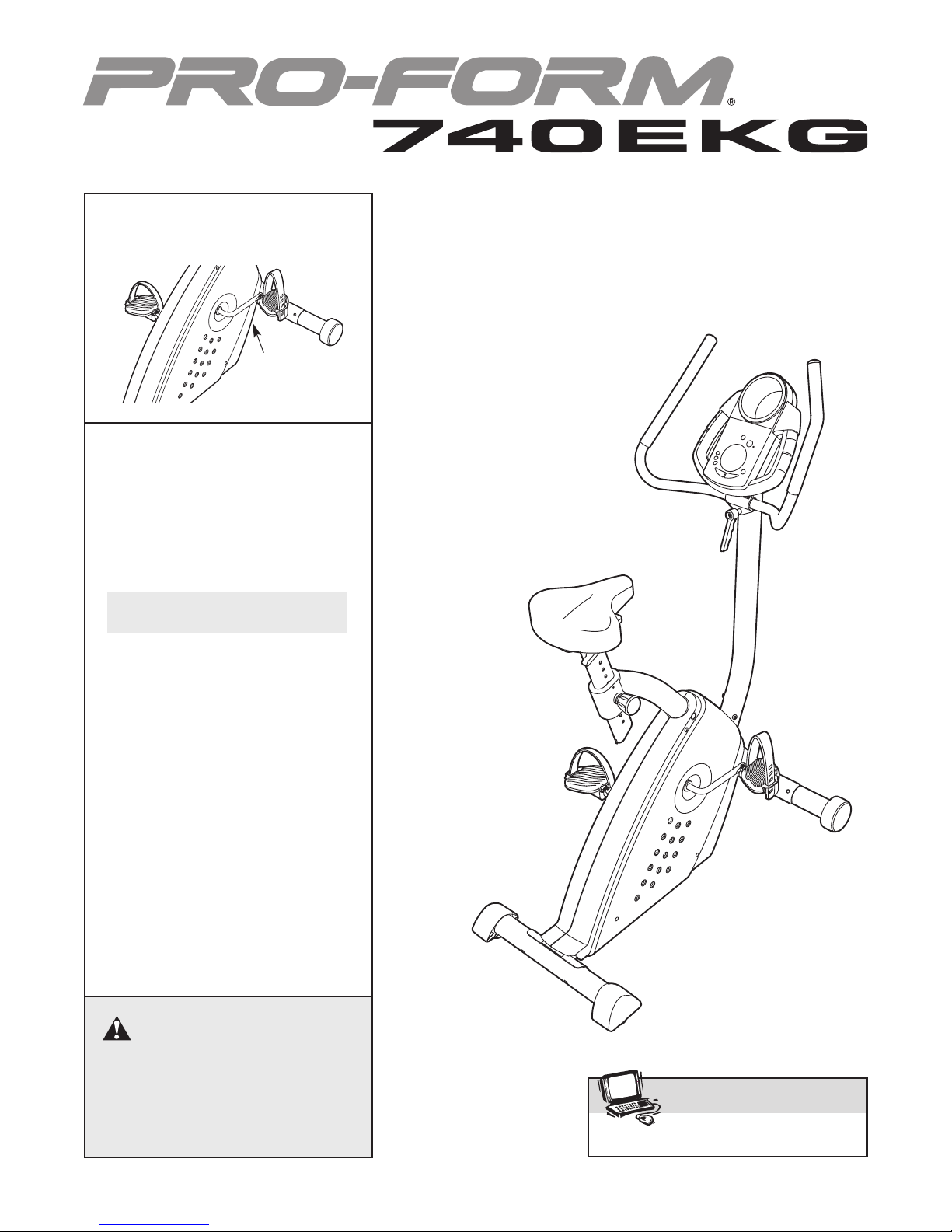
12.A warning decal has been placed on the exercise cycle in the location shown on page 3. If
the decal is missing, or if it is not legible, call
the telephone number on the front cover of
this manual and order a free replacement
decal. Apply the decal in the location shown.
WARNING: Before beginning this or any exercise program, consult your physician. This
is especially important for persons over the age of 35 or persons with pre-existing health problems.
Read all instructions before using. ICON assumes no responsibility for personal injury or property
damage sustained by or through the use of this product.
2

BEFORE YOU BEGIN
Congratulations for selecting the new PROFORM®740
EKG exercise cycle. Cycling is one of the most effective exercises for increasing cardiovascular fitness,
building endurance, and toning the body. The 740
EKG exercise cycle offers a selection of features
designed to let you enjoy this healthful exercise in the
convenience and privacy of your home.
For your benefit, read this manual carefully before
you use the exercise cycle. If you have questions
Handlebar
Console
Handlebar Handle
after reading this manual, see the front cover of this
manual. To help us assist you, please note the product
model number and serial number before contacting us.
The model number is PFEVEX2915.0. The serial number can be found on a decal attached to the exercise
cycle (see the front cover of this manual for the location of the decal).
Before reading further, please familiarise yourself with
the parts that are labelled in the drawing below.
Accessory Tray
Handgrip Pulse Sensor
Seat
Seat Bracket Handle
Seat Knob
REAR
Levelling Foot
Pedal/Strap
RIGHT SIDE
3
ASSEMBLY
M8 Nylon
Locknut (10)–6
M8 Split Washer
(41)–10
M10 Nylon
Locknut (33)–4
M4 x 16mm
Screw (49)–4
M8 x 25mm Button
Screw (45)–6
M10 x 75mm Carriage Bolt (30)–4
M6 x 8mm Screw
(28)–2
Assembly requires two persons. Place all parts of the exercise cycle in a cleared area and remove the packing
materials. Do not dispose of the packing materials until assembly is completed.
Assembly requires the included tools and your own adjustable spanner and Phillips screwdriver .
Use the drawings below to identify the small parts needed for assembly. The number in parentheses below each
drawing is the key number of the part, from the PART LIST on page 14. The number following the key number is
the quantity needed for assembly. Note: Some small parts may have been preassembled. If a part is not in
the parts bag, check to see if it has been preassembled.
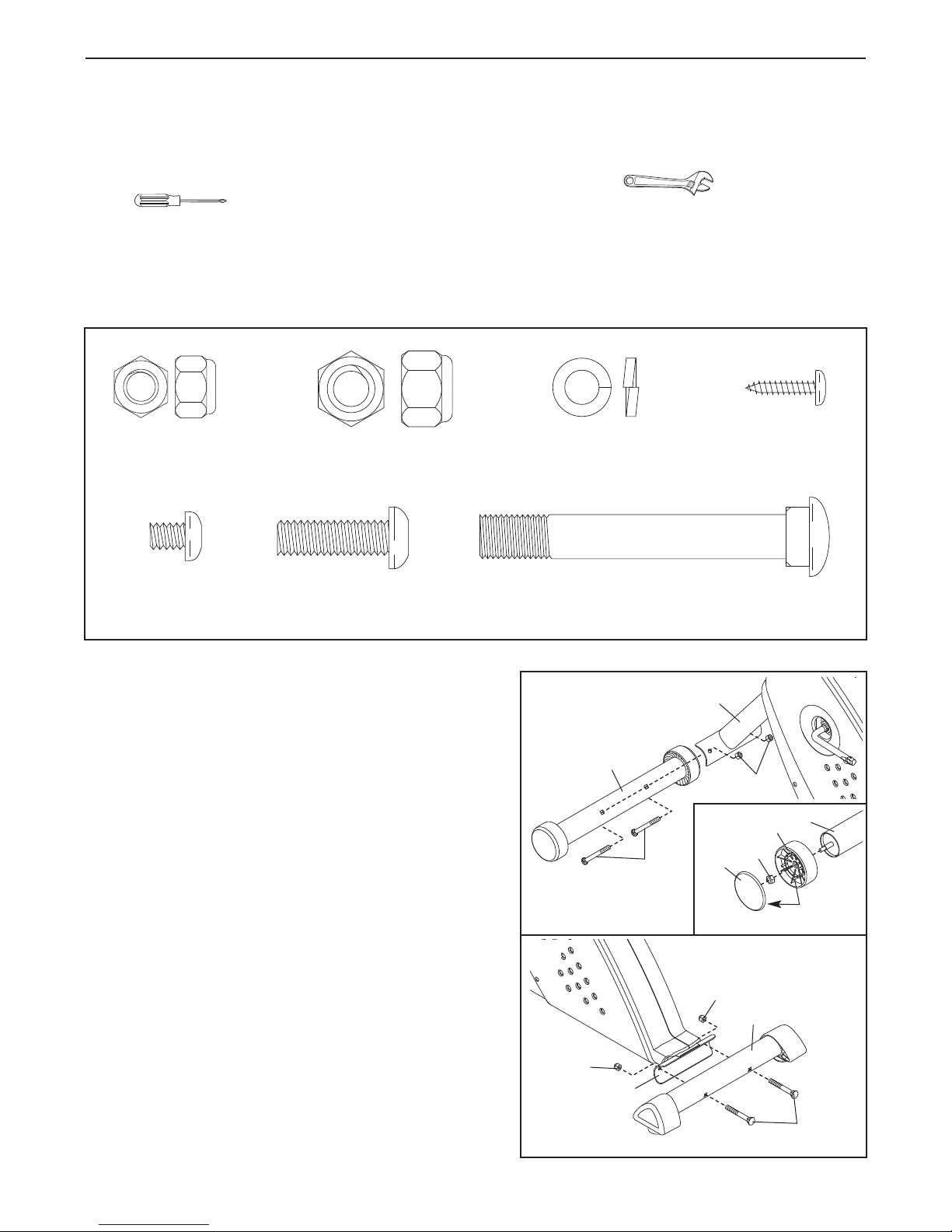
1. Identify the Front Stabiliser (2). See the inset drawing.
Attach a Wheel (14) to one end of the Front Stabiliser
with an M8 Nylon Locknut (10). Make sure that the
Wheel is turned as shown and that it turns freely.
Next, align the four plastic posts on a Wheel Cover
(23) with the plastic posts on the Wheel, and press the
Wheel Cover onto the Wheel. Assemble the other
Wheel (not shown) in the same way.
Whilst another person lifts the front of the Frame (1),
attach the Front Stabiliser (2) to the Frame with two
M10 x 75mm Carriage Bolts (30) and two M10 Nylon
Locknuts (33) as shown.
2. Whilst another person lifts the rear of the Frame (1),
attach the Rear Stabiliser (6) with two M10 x 75mm
Carriage Bolts (30) and two M10 Nylon Locknuts (33).
1
2
33
1
2
33
2
14
10
30
1
23
Post
33
6
4
30
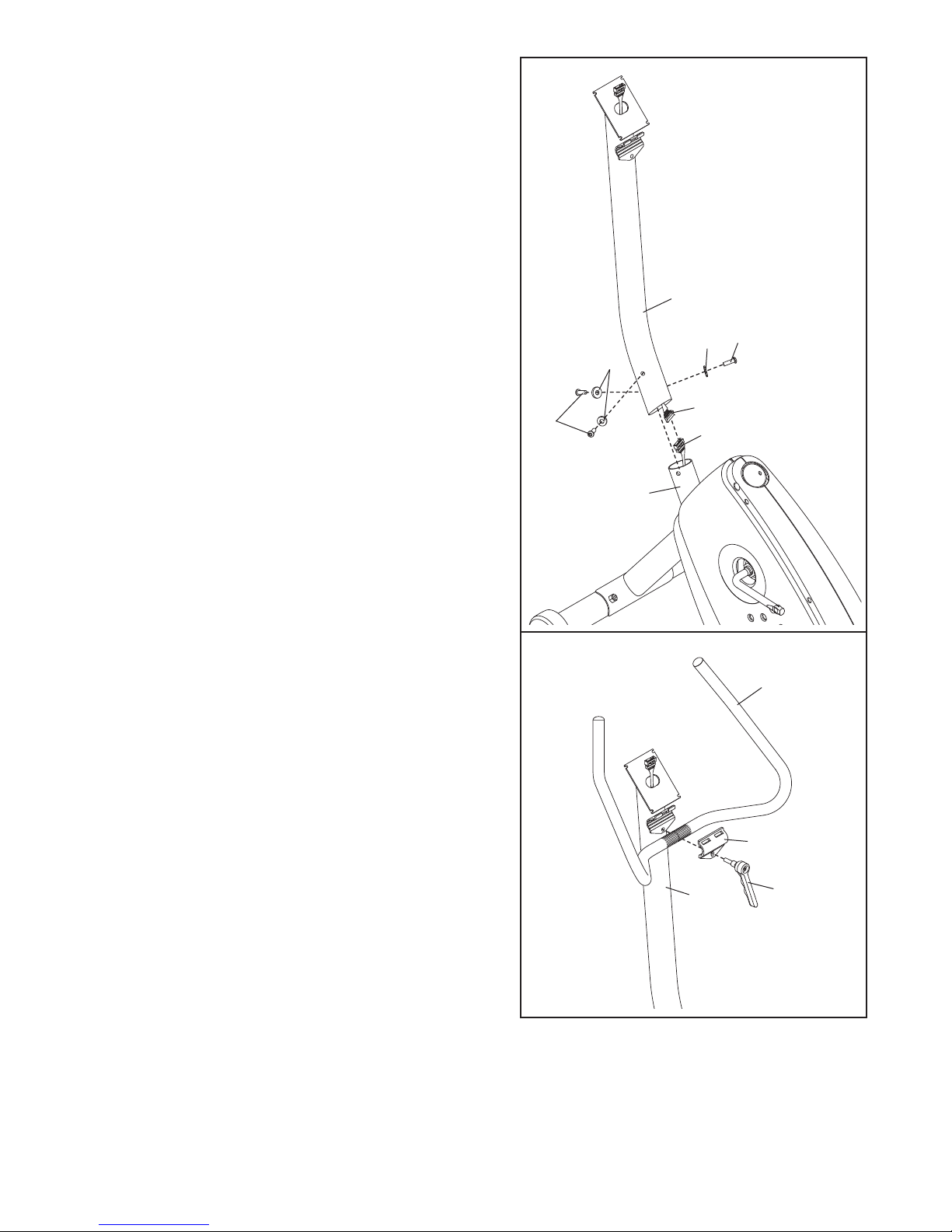
3. Whilst another person holds the Upright (13) in the
position shown, connect the Upper Wire Harness (36)
to the Lower Wire Harness (55).
Carefully pull the excess Upper Wire Harness (36) out
f the top of the Upright (13), and slide the Upright onto
o
the Frame. Be careful to avoid pinching the Wire
Harnesses. Next, attach the Upright with three M8 x
25mm Button Screws (45) and three M8 Split Washers
(41).
3
Be careful to avoid
pinching the wire
harnesses whilst
attaching the
upright.
13
45
41
41
4. Identify the Handlebar Handle (9), which has a longer
threaded shaft than the Seat Bracket Handle (not
shown).
Attach the Handlebar (15) to the Upright (13) with the
Handlebar Bracket (58) and the Handlebar Handle (9).
Note: The Handlebar Handle functions like a spanner.
Turn the Handle clockwise, pull it away from the
Upright, turn it counterclockwise, push it toward the
Upright, and then turn it clockwise again. Repeat this
process until the Handle is tight.
45
1
4
36
55
15
58
13
9
5
 Loading...