

Page 1
PERFORMANCE TREADMILL
8 ARS
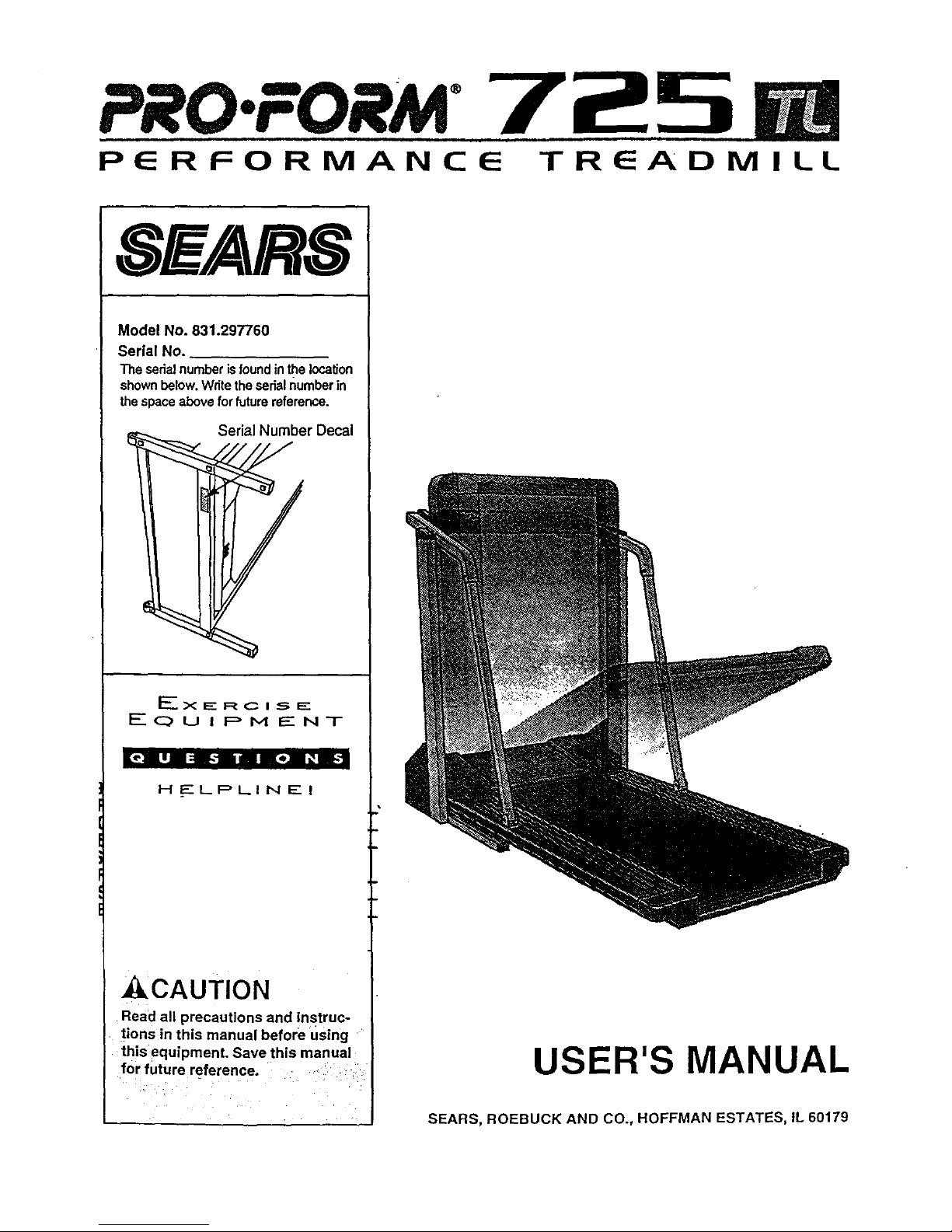
Model No. 831.297760
Serial No.
The serialnumberisfoundinthelocation
shownbelow.Writetheserialnumberin
thespaceabovefor futurereference.
Serial Number Decal
EXERCISE
EQ u i F> Iyl _" NT
[_'ll i ;BILl I lel + ii-"
H ELPLINE!
_kCAUTION
Read all precautions and instruc-
tions in this manual before Using "
this equipment save th s manua
for future reference.
USER'S MANUAL
SEARS, ROEBUCK AND CO., HOFFMAN ESTATES, IL 60179
Page 2
TABLE OF CONTENTS
FULL 90 DAY WARRANTY ................................................................... 2
IMPORTANT PRECAUTIONS ................................. ._............................... 3
BEFORE YOU BEGIN ....................................................................... 5
ASSEMBLY ............................................................................... 6
HOW TO USE THE PULSE SENSOR ........................................................... 8
OPERATION AND ADJUSTMENT ............................................................. 9
HOW TO USE THE MANUAL MODE .................................................. .. .. .. 11
HOW TO USE THE WEIGHT LOSS PROGRAMS AND THE INTERVAL PROGRAMS ................. 13
HOW TO USE THE FAT BURN AND AEROBIC PROGRAM ..................................... 15
HOW TO USE THE FITNESS TEST PROGRAM ............................................... 16
HOW TO FOLD AND MOVE THE TREADMILL .................................................. 18
TROUBLE-SHOOTING ..................................................................... 20
CONDITIONING GUIDELINES ............................... : ............................... 22
ORDERING REPLACEMENT PARTS ................................................. ".Back Cover
Note: An EXPLODED DRAWING and a PART LIST are attached to the center of this manual. Please save them
for future reference.
2
FULL 90 DAY WARRANTY
For 90 days from the date of purchase, if failure occurs due to defect in material or workmanship in this
SEARS TREADMILL EXERCISER, contact the nearest SEARS Service Center throughout the United
States and SEARS will repair or replace the TREADMILL EXERCISER, free of charge.
This warranty does not apply when the TREADMILL EXERCISER is used commerciallyor for rental pur-
poses.
This warranty gives you specific legal rights, and you may also have other rights which vary from state
to state.
SEARS, ROEBUCK AND CO., DEPT. 817WA, HOFFMAN ESTATES, IL 60179
Page 3
IMPORTANT PRECAUTIONS
A=WAR NING: To reduce the risk of burns, fire, electric shock, or injury to persons, read the
following important precautions and information before operating the treadmill.
1. It Is the responsibility of the owner to ensure
that all users of this treadmill are adequately
informed of all warnings and precautions.
2." Use the treadmill only as described in thls
• manual.
3. Place the treadmill on a level surface, with 8
feet of clearance behind it. Do not place the
treadmill on any surface that blocks air open-
ings. To protect the floor or carpet from dam-
age, place a mat under the treadmill.
4. Keep the treadmill indoors, away from mois-
ture and dust. Do not put the treadmill in a
garage or covered patio, or near water.
5. Do not operate the treadmill where aerosol
products are used or where oxygen is being
administered.
6. Keep small children anti pets away from the _
treadmill at all times.
• 7. The treadmill should be used only by persons
3 weighing 250 pounds or less.
8: Never allow more than one person On the
treadmill at a time.
9. Wear appropriate exercise clothing when
using the treadmill. Do not wear loose cloth-
ing that could become caught in the treadmill.
Athletic support clothes are recommended for
both men and women. A/ways wear athletic
shoes. Never use the treadmill with bare feet,
wearing only stockings, or In sandals.
10. When connecting the power cord (see HOW
TO PLUG IN THE POWER CORD on page 9),
plug the power cord Into a surge protector
(not included) and plug the surge protector
into a grounded circuit capable of carrying 15
or more amps. No other appliance should be
on the same circuit.
11. Use only a UL-listed surge protector, rated at
15 amps, with a 14-gauge cord of five feet or
less in length. Do not use an extension cord.
12. Keep the power cord and the surge protector
away from heated surfaces.
13. Never move the walking belt while the power
is turned off. Do not operate the treadmill if
the power cord or plug is damaged, or If the
treadmill Is not working properly. (See BE-
' - FORE YOU BEGIN on page 5 if the treadmill Is
not working properly.)
14. Never start the treadmill while you are stand-
ing on the walking belt. Always hold the
handrails while using the treadmill.
15. The treadmill is capable of high speeds.
Adjust the speed in small increments to avoid
sudden jumps in speed.
16.To reduce the possibility of the treadmill over-
he;_ting, do not operate the treadrnlll contlnu.
_sly for longer than I hour.
17. The pulse sensor is not a meomal oevice.
Various factors, including the user's move-
ment, may affect the accuracy of heart rate
readings. The pulse sensor is intended only
as an exercise aid in determining heart rate
trends in general.
18.
Never leave the treadmill unattended while it
is running. Always remove the key and move
the on/off switch to the "off" position when
the treadmill is not in use. (See the drawing on
page 5 for the location of the on/off switch.)
19. Do not attempt to raise, lower, or move the
treadmill until it is properly assembled. (See
ASSEMBLY on page 6, and HOW TO MOVE
THE TREADMILL on page 19.) You must be
able to safely lift 45 pounds (20 kg) to raise,
lower, or move the treadmill.
20. When folding or moving the treadmill, make
sure that the storage latch is fully closed.
21. During the last ten seconds of a preset pro-
gram, the treadmill will automatically adjust to
the lowest incline level. Keep your feet and ob-
jects from beneath the treadmill.
3
Page 4
22. Inspect and tighten all parts of the treadmill
every three months.
23. Never insert any object into any opening.
24. Always unplug the power'cord before per-
forming the maintenance and adjustment
procedures described in this manual. Never
remove the motor hood unless instr-cted to
do so by an authorized service representa-
tive. Servicing other than the procedures in
this manual should be performed by an au-
thorized service representative only.
25. This treadmill Is intended for In-home use
only. Do not use this treadmill in any com-
mercial, rental, or institutional settina.
• WARNING ;'Before beginning this or any exercise program, consult your physician. This
is espec!ally importantfor'l_er.sons over the age of 35 or persons with pre-existing health problems.
Read all instructions before using. SEARS assumes no responsibility for personal Injury or property
dama_qesustained b_vor'through the use of this croducL
SAVE THESE INSTRUCTIONS
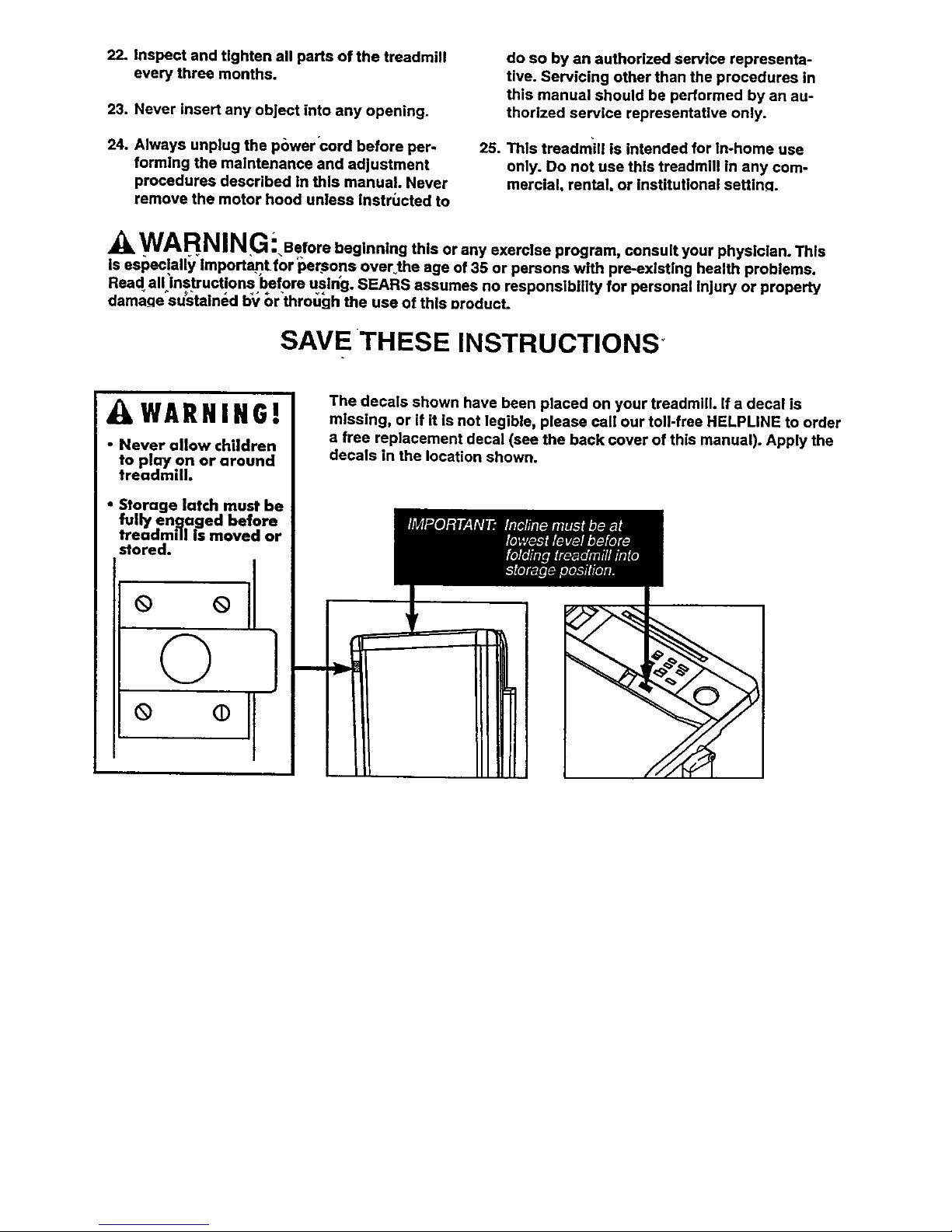
AWARNING!
• Never allow children
to plm/on or around
treadmill.
• Storage latch must be
fully engaged before
treadmill is moved or
stored.
° °11
© }
°
The decals shown have been placed on your treadmill, if a decal is
missing, or if it is not legible, please call our toll-free HELPUNE to order
a free replacement decal (see the back cover of this manual). Apply the
decals in the location shown.
Page 5

BEFORE YOU BEGIN
Thank you for selecting the PROFORM = 725 TL tread-
mill. The 725 TL treadmill blends advanced technology
with innovative design to let you enjoy an excellent
form of cardiovascular exercise in the convenience
and privacy of your home.
For your benefit, read this manual carefully before
using the treadmill. If you have additional questions,
please call our toll-free HELPLINE at 1-800-736-6879,
Monday through Saturday, 7 a.m. until 7 p.m. Central
Time (excluding holidays). To help us assist you,
please note the product model number and serial num-
ber before calling. The model number of the treadmill
is 831.297760. The serial number can be found on a
decal attached to the treadmill (see the front cover of
this manual for the location).
Before reading further, please review the drawing
below and familiarize yourself with the parts that are
labeled.
Book
Console Rack
Storag_
Power Cord
On/Off Switch
Circuit Breaker
Water Bottle Holder
(Water Bottle is not
included)
Belt
Foot Rails
Front Wheel
LEFT SIDE
Cushioned Walking
Adjustment Bolt
BACK
Page 6
ASSEMBLY
Assembly requires two people. Set the treadmill in a cleared area and remove the packing materials. Do not dis-
pose of the packing materials untilassembly is completed. Assembly requires the included allen wrench _ .
._J
°
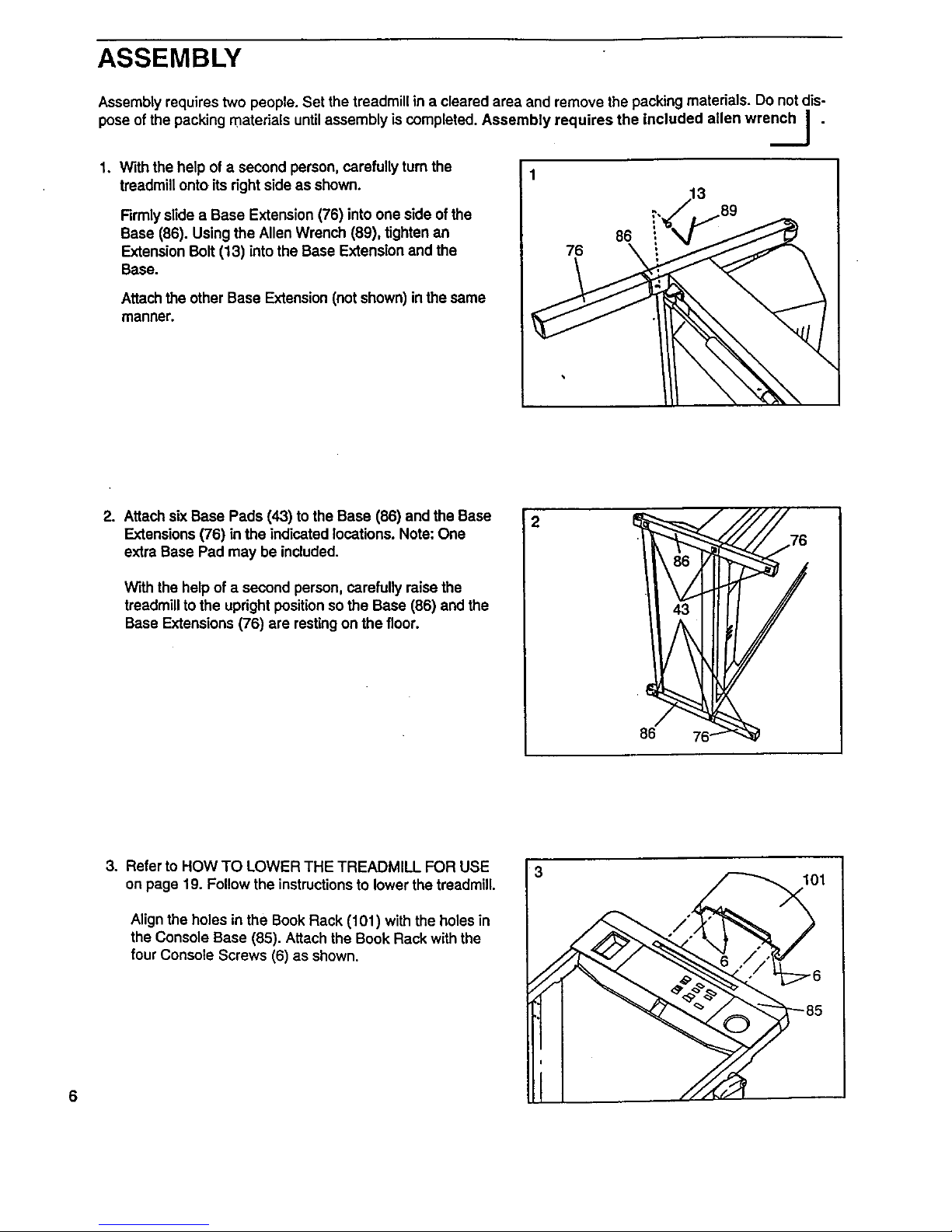
With the help of a second person, carefully turn the
treadmill onto its right side as shown.
Firmly slide a Base Extension (76) into one side of the
Base (86). Using the Allen Wrench (89), tighten an
Extension Bolt (13) into the Base Extension and the
Base.
Attach the other Base Extension (not shown) in the same
manner.
86
76
2. Attach six Base Pads (43) to the Base (86) and the Base
Extensions (76) in the indicated locations. Note: One
extra Base Pad may be included.
With the help of a second person, carefully raise the
treadmill to the upright positionso the Base (86) and the
Base Extensions (76) are resting on the floor.
86
6
3° Refer to HOW TO LOWER THE TREADMILL FOR USE
on page 19. Follow the instructions to lower the treadmill.
Align the holes in the Book Rack (101) with the holes in
the Console Base (85). Attach the Book Rack with the
four Console Screws (6) as shown.
3
1oi
Page 7
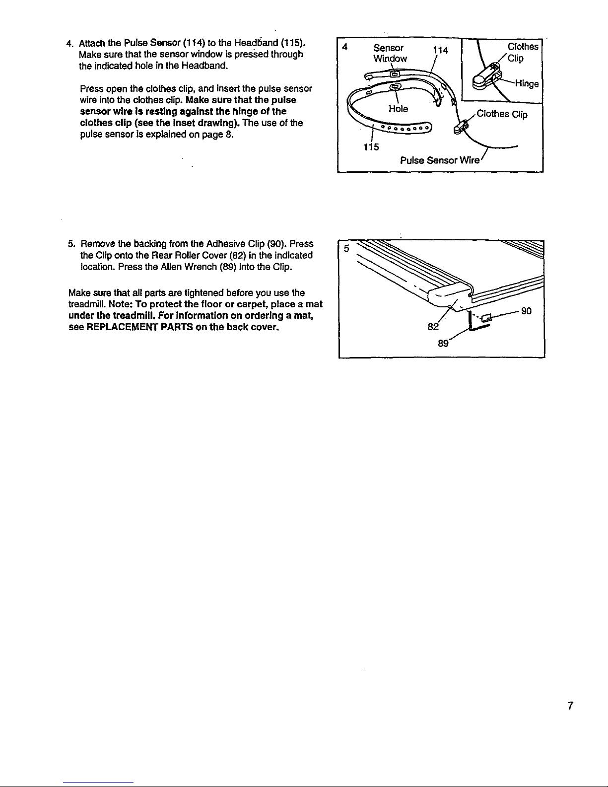
4. Attach the Pulse Sensor (114) to the Head6and (115).
Make sure that the sensor window is pres_sed through
the indicated hole in the Headband.
Press open the clothes clip, and insert the pulse sensor
wire into the clothes clip. Make sure that the pulse
sensor wire is resting against the hinge of the
clothes clip (see the Inset drawing). The use of the
pulse sensor is explained on page 8.
4 Sensor 114 I \ Clothes
_Clothes Clip
115 Pulse Sensor Wire"_
5. Remove the backing from the Adhesive Clip (90). Press
the Clip onto the Rear Roller Cover (82) in the indicated
location. Press the Allen Wrench (89) into the Clip.
Make sure that all parts are tightened before you use the
treadmill. Note: To protect the floor or carpet, place a mat
under the treadmill. For Information on ordering a mat,
see REPLACEMENT PARTS on the back cover.
89
7
Page 8
HOW TO USE THE PULSE SENSOR
The unique headband-style pulse sensor is specially
designed for greater accuracy, comfort, and durability.
To get the best performance from the pulse sen-
sor, please read the following instructions.
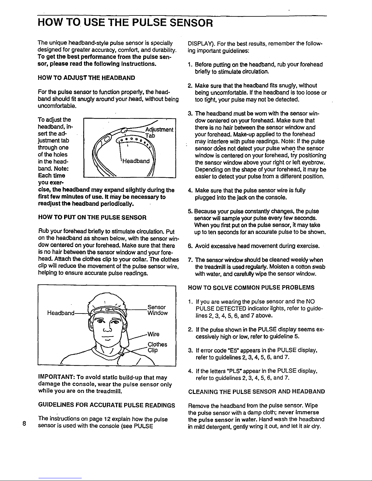
HOW TO ADJUST THE HEADBAND
For the pulse sensor to function properly, the head-
band should fit snugly around your head, without being
uncomfortable.
To adjust the
headband, in-
sertthe ad-
justment tab
through one
ofthe holes
in the head-
band. Note:
Each time
ent
you exer-
cise, the headband may expand slightly during the
first few minutes of use. It may be necessary to
readjust the headband periodically.
HOW TO PUT ON THE PULSE SENSOR
Rub your forehead briefly to stimulate circulation. Put
on the headband as shown below, with the sensor win-
dow centered on your forehead. Make sure that there
isno hair between the sensor window and your fore-
head. Attach the clothes clip to your collar. The clothes
clip will reduce the movement of the pulse sensor wire,
helping to ensure accurate pulse readings.
Sensor
Window
Clothes
/
IMPORTANT: To avoid static build-up that may
damage the console, wear the pulse sensor only
while you are on the treadmill.
GUIDELINES FOR ACCURATE PULSE READINGS
The instructions on page 12 explain how the pulse
sensor is used with the console (see PULSE
DISPLAY). For the best results, remember the follow-
ing important guidelines:
1. Before putting on the headband, rub your forehead
briefly to stimulate circulation.
2. Make sure that the headband fits snugly, without
being uncomfortable. If the headband is too loose or
too tight, your pulse may not be detected.
3. The headband must be wom with the sensor win-
dow centered on your forehead. Make sure that
there is no hair between the sensor window and
your forehead. Make-up applied to the forehead
: may interfere with pulse readings. Note: If the pulse
sensor does not detect your pulse when the sensor
window is centered on your forehead, try positioning
the sensor window above your right or left eyebrow.
Depending on the shape of your forehead, itmay be
easier to detect your pulsefrom a different position.
4. Make sure that the pulse sensor wire is fully
plugged intothe jack on the console.
S.
Because your pulse constantly changes, the pulse
sensor will sample your pulse every few seconds.
When you first put on the pulse sensor, it may take
up toten seconds for an accurate pulse to be shown.
8. Avoid excessive head movement during exercise.
7. The sensor window should be cleaned weekly when
the treadmill is used regularly. Moisten a cotton swab
with water, and carefully wipe the sensor window.
HOW TO SOLVE COMMON PULSE PROBLEMS
1. If you are wearing the pulse sensor and the NO
PULSE DETECTED indicator lights, refer to guide-
lines 2, 3, 4, 5, 6, and 7 above.
2. If the pulse shown in the PULSE display seems ex-
cessively high or low, refer to guideline 5.
3. Iferror code "E5" appears in the PULSE display,
refer to guidelines 2, 3, 4, 5, 6, and 7.
4. If the letters "PLS" appear in the PULSE display,
refer to guidelines 2, 3, 4, 5, 6, and 7.
CLEANING THE PULSE SENSOR AND HEADBAND
Remove the headband from the pulse sensor. Wipe
the pulse sensor with a damp cloth; never immerse
the pulse sensor in water. Hand wash the headband
in mild detergent, gently wring it out, and let it air dry.
Page 9
OPERATION AND ADJUSTMENT
THE PERFORMANT LUBE TM WALKING BELT
Your treadmill features a walking belt coated with
PERFORMANT LUBETM, a high-performance lubricant.
IMPORTANT: Never apply silicone sprayor other
substances to the walking belt or the walking plat-
form. They will deteriorate the walking belt and
cause excessive wear.
HOW TO PLUG IN THE POWER CORD
:;/ _ "./. .::_...i. >. : _i_;: i:,'!!'. "'_.:_il_"
DANGER" .....
• Improper connection
_:of the equipnlent-gr0und!ng coriductor_n
r_sult in an increased ris!(of el_ctdc sh()ck. ;'
iCl_ieck Witl_ aqualified ele_tPici_or se'_ice -
i :_ma'nff you are in doubt as to Wl_ther t_e
Pr_ddctls properlygrou_!i_ed- Do:hot modify :
; _e plug P_;0vided _ith thelprod_ct_--tf itlwill
; ;_n0tfit the oi,tlet, have a proper Outlet In_::
;:_sta led' byaqua fled e eCtL'iclan; _i: • ;ii:_ii:_ /
Your treadmill, like any other type of sophisticated
electronic equipment, can be seriously damaged by
sudden voltage changes in your home's power.
Voltage surges, spikes, and noise interference can re-
suit from weather conditions or from other appliances
being turned on or off.
To decrease the pos-
sibility of your tread- 1
mill being damaged,
always use a surge
protector (not in-
cluded) with your
treadmill.
Surge prote_:tors are
sold at most hardware
stores and department
stores. Use only a UL-
listed surge protector,
rated at 15 amps, with a
14-gauge cord of five
feet or less in length.
This product must be
grounded. If it should
malfunction or break
down, grounding pro-
vides a path of least re-
sistance for electric cur-
rent to reduce the risk of
electric shock. This product is equipped with a cord
having an equipment-grounding conductor and a
grounding plug. Plug the power cord into a surge
protector, and plug the surge protector Into an ap-
propriate outlet that Is properly Installed and
grounded in accordance with all local codes and
ordinances.
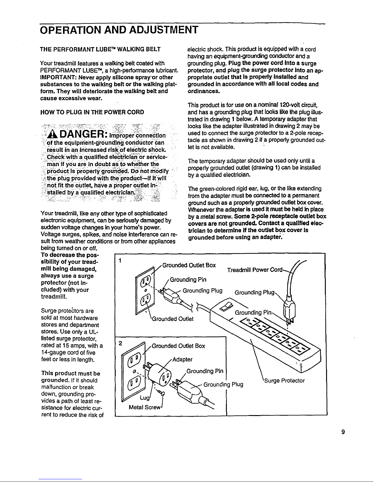
This product isfor use on a nominal 12g-volt circuit,
and has a grounding plug that looks like the plug illus-
trated in drawing 1 below. A temporary adapter that
looks like the adapter illustrated in drawing 2 may be
used to connect the surge protector to a 2-pole recep-
tacle as shown in drawing 2 ifa propedy grounded out-
let is not available.
The temporary adapter should be used only until a
properly grounded outlet (drawing 1) can be installed
by a qualified electrician.
The green-colored rigid ear, lug, or the like extending
from the adapter must be connected to a permanent
ground such as a properly grounded outlet box cover.
Whenever the adapter is used it must be held in place
by a metal screw. Some 2-pole receptacle outlet box
covers are not grounded. Contact a qualified elec-
trician to determine if the outlet box cover is
grounded before using an adapter.
_Grounded Outlet Box
j Grounding Pin
"_unding Plug
3rounded Outlet
Treadmill Power Cord-..
Grounding Plug_
O._I ,_Grounded Outlet Box
Adapter
;g_ .Grounding Pin
- ]j
_J_, __ Grounding Plug
Metal Screw _ I
Surge Protector
9
Page 10

)IAGRAMOFTHECONSOLE
TRAINII_G
ZONES
Clip--
:Note: If there is a thin sheet of clear plas-
tic on the face of the console, remove it.
FEATURES OF THE CONSOLE
The treadmill console offers an impressive array of fea-
tures designed to make YOUrworkouts more effective
and enjoyable. When the console is in the manual mode,
the speed and incline of the treadmill can be changed
with a touch of a button. As you exemise, five displays
will provide continuous exercise feedback. Seven preset
programs are also offered: two WEIGHT LOSS programs
and two INTERVAL programs automatically control the
speed of the treadmill as they guide you through effective
workouts; the special FAT BURN program provides in-
tensive fat-burning workouts; the AEROBIC program
helps you to achieve maximum cardiovascular benefits;
and the unique FITNESS TEST program measures your
relative fitness level.
To use the manual mode, follow the steps on pages 11
through 13. To use the WEIGHT LOSS or INTERVAL
programs, see pages 13 and 14. To use the FAT BURN
or AEROBIC program, see pages 15 and 16. To use the
FITNESS TEST program, see pages 16 and 17. Note:
The console can display speed and distance in either
miles or kilometers (see SPEED DISPLAY on page 12).
For simplicity, all instructions in this manual refer to miles.
Before beginning, make sure
that the on/off switch located
near the power cord is in the
"on" position. Plug in the power
cord (see page 9). Note: If the
key is in the console when the
"On"
Position
power cord is plugged in, the letters "PO" will flash in the
SPEED display. If this occurs, remove the key.
Page 11

:/' HOW TOUSE EMANUALMODE_; _: ._:_:,_
B Insert the key fully into the console.
Stand on the foot rails
and insert the key.
Various displays and in-
dicators will light. Find
the clip attached to the
key and slide itonto the
waistband of your cloth-
ing.
A
Select the MANUAL mode.
When the key is in-
serted, the manual .
mode will automatically
be selected. The MAN-
UAL CONTROL indica-
tor will light. Note: if a
preset program has
been selected, press the MODE button repeatedly
to select the manual mode again.
k3
Enter your weight, if desl_ed.
Although it is not necessary to enter your weight and
age to use the manual mode, the CALORIES dis-
play will be more accurate if your weight and age
are entered. To enter your weight:
• Press the
WEIGHT in-
crease or de-
crease button.
The letters
"LbS" will flash
in the CALO-
RIES display. Press one of the WEI,GHT buttons
again. The current weight setting will then be
shown. Press the WEIGHT buttons again to enter
your weight. Each time one of the buttons is
pressed, the weight setting will change by 1
pound. •If one of the buttons is held down, the
weight setting will change in increments of 5
pounds. After you have entered your weight, your
weight will be shown in the CALORIES display for
three seconds.
B Enter your age, if desired.
To enter your age:
• Press the AGE increase or decrease button. The
letters "AGE" will flash in the PULSE display.
Press one of the AGE buttons again. The current
age setting will then be shown. Press the AGE
buttons again to enter your age. Each time one of
the buttons is pressed, the age setting will change
by 1 year. If one of the buttons is held down, the
age setting will change in increments of 5 years.
After you have entered your age, your age will be
shown in the PULSE display for three seconds.
Note: Once you have entered your weight and age,
the numbers will be saved in the console's memory,
even if the power cord isunplugged.
Put on the pulse sensor, if desired.
For the PULSE dis-
play to show your
pulse, the pulse sen-
sor must be worn. To
put on the pulse sen-
sor, see HOW TO
USE THE PULSE SENSOR on page 8. Plug the
pulse sensor fully intothe jack on the front of the
console.
r_ Press the SPEED increase button to start the
walking belt.
The speed of
the walking
belt is con-
trolled with
the SPEED
increase and
decrease but-
L__.__.J
tons. Each time one of the buttons is pressed, the
speed will change by 0.1 mile per hour (mph). The
buttons can be held down to change the speed
quickly. The speed range is 0.5 mph to 10 mph.
Press the SPEED increase button untilthe walking
belt begins to move at slow speed. Hold the
handrails and carefully begin walking. Change the
speed of the walking belt as desired by pressing the
SPEED buttons. Note: The walking belt can also be
started by pressing the START/PAUSE button. The
walking belt will begin to move at 0.5 mph. The
speed can then be adjusted with the SPEED buttons.
To stop the walking belt, press the START/PAUSE
button. All displays will pause and the TIME display
will begin to flash. To restart the walking belt, press
the SPEED buttons or the START/PAUSE button as
described above. Note: The walking belt can also be
stopped by pressing the STOP button. To restart the
walking belt, press the SPEED buttons or the
START/PAUSE button as described above.
Note: When the SPEED buttons are pressed, the
SPEED display willshow the selected speed setting
for seven seconds. The display will then show the
actual speed of the walking belt.
11
Page 12

B
Change the incline of t_etreadmill, if desired.
The incline of the tread-
mill is controlled with the
INCLINE increase and
decrease buttons. Each
time one of the buttons
is pressed, the incline
will change by 0.5%.
I I
The buttons can be held down to change the incline
quickly. The incline setting is shown in the DIS-
TANCE/INCUNE display. The incline range is 1.5%
to 10%. Note: After the INCLINE buttons are
pressed, it may take a few seconds for the treadmill
•to reach the selected incline setting.
l_l Follow your progress with the five displays and
the TRAINING ZONE monitor.
•"CALORIES display
This display shows
both the total calories
and the number of fat
calodes that you have
burned. (See BURN-
ING FAT on page 22
for an explanation of fat calories). Every seven
seconds, the display will change from one number
to the other. The FAT indicator beside the display
will light when the number of fat calodes is shown.
Note: This display also shows the current weight
setting when the walking belt is stopped and the
WEIGHT buttons are pressed.
• PULSE dlsplay
For this display to op-
erate, the pulse sen-
sor must be worn (see
HOW TO USE THE
PULSE SENSOR on
page 8). After a few
seconds, the heart-
I_0_o CALORIES ]
°1"o
PULSE
shaped indicator beside the PULSE display will
flash each time your heart beats, the NOT DE-
TECTED indicator will darken, and your pulse will
be shown. Note: Because your pulse constantly
changes, the pulse sensorwill sample your pulse
every few seconds. It may take up to ten seconds
before an accurate pulse is shown. If your pulse is
not shown, see GUIDELINES FOR ACCURATE
PULSE READINGS on page 8.
Note: This display also shows the current age set-
ting when the walking belt isstopped and the AGE
buttons are pressed.
SPEED display
This display shows
the current speed of
the walking belt.
When the SPEED
buttons are pressed,
the display willshow
the selected speed setting for seven seconds. The
display will then show the actual speed of the
walking belt.
Note: The speed can be displayed in either miles
per hour (mph) or kilometers per hour (kph). The
indicators beside the SPEED display will light to
show which unitof measurement is selected. To
change the unit ofmeasurement, first hold down
the STOP button while inserting the key into the
console. An "E" (for Englishsystem [miles]) or "M"
(for Metdc system [kilometers])will appear in the
SPEED display. Press the SPEED increase button
to change the unitof measurement. Remove and
then reinsert the key.
• TIME display
This display shows
the total time that the
walking belt has
been moving.
II!-.-!I1-1"_11-}]
t_-._t..,,_ TIME
Note: When any pro-
gram except the RTNESS TEST program is se-
lected, the TIME display will show the time re-
maining in the program.
DISTANCE/INCLINE display
This display shows
both the distance
that the walking belt
has moved and the
current incline of the
treadmill. Every
seven seconds, the
display will change
from one number to the other. When the INCLINE
buttons are pressed, the display will change to
show the selected inclinesetting.
Note: If the MPH indicator beside the SPEED dis-
play is lit, the distance will be displayed in miles. If
the KPH indicator is lit, the distance will be dis-
played in kilometers.
Page 13

• Training Zone Monitor i I
The training zone monitor ZONeS_N_"a
measures the approximate i _),_.,,,,-
intensity of your exercise, i _).,,.._
The monitor's five indicators
are described below: i _)_="*_'_
i i
• WARM UP & COOL ! _)_
DOWN--Each workout ,
should begin with a warm- I ! Oo
up period and end with a
cool-down period. (See WORKOUT GUIDE-
LINES on pages 22 and 23.) The WARM-UP &
COOL-DOWN indicator will light when your
workout intensity is ideal for warming up or cool-
ing down.
• FAT BURN and MAXIMUM FAT BURN--To
bum fat effectively, you must exercise at a rela-
tively low intensity level for a sustained period of
time. (See BURNING FAT on page 22.) If you
are exercising at the proper intensity level for
burning fat, the FAT BURN or MAXIMUM FAT
BURN indicator will light.
• AEROBIC--If your goal is to strengthen your
cardiovascular system, your exercise must be
"aerobic." (See AEROBIC EXERCISE on page
22.) Ifyou are exercising at the proper intensity
level for aerobic exercise, the AEROBIC indica-
tor will light.
• PERFORMANCE--If your goal is high perfor-
mance athletic conditioning, you will need to ex-
ercise at a high intensity level. If you are exercis-
ing at the proper intensity level, the PERFOR-
MANCE indicator will light.
[] When you are finished exercising, stop the walk-
ing belt and remove the key.
Step onto the foot rails and stop the walking belt.
Lower the treadmill to the lowest incline level.
Remove the key from the console and store the key
in a secure place. In addition, move the on/off switch
to the "off" position. (See the drawing near the bot-
tom of page 10.)
'_:'":HO_TO:"USE ' '":'THEWEIGHT"" _O_ __ "
The WEIGHT LOSS programs and the INTERVAL
programs automatically control the speed of the walking
belt as they guide you through effective workouts. The
WEIGHT LOSS programs focus on helping you to lose
unwanted pounds; the INTERVAL programs ere
designed to build stamina. The WEIGHT LOSS programs
and the INTERVAL 1 program are 20-minute programs;
the INTERVAL 2 program isa 30-minute program. The
graphs on the left side of the console show how the
speed will change during each program. During the
WEIGHT Loss I program, for example, the speed will
gradually increase during the first 10 minutes, and then
gradually decrease during the last 10 minutes. Each
program begins with a 2-minute warm-up period, and
ends with a 2=minute cool-down period.
Follow the steps below to use one of these programs.
D Make sure that the key is fully inserted into the
console.
Stand on the foot rails
and insert the key.
Various displays and
indicators will light.
Find the clip attached
to the key, and slide it
onto your waistband.
A
B Select the WEIGHT LOSS 1, WEIGHT LOSS 2,
INTERVAL 1, or INTERVAL 2 program.
el
When the key is inserted,
the MANUAL CONTROL
indicator will light. To select
the WEIGHT LOSS 1 pro-
gram, press the MODE but-
ton. The WEIGHT LOSS 1
indicator will light. To select
one of the other programs,
press the MODE button re-
peatedly until the WEIGHT LOSS 2, INTERVAL 1,
or INTERVAL 2 indicator lights. Note: If the walking
belt is moving, itwill slow to a stop.
MOOE
-_ V we_Hr A
Enter your weight, if desired. "_-,
When a WEIGHT LOSS or INTERVAL program is
selected, the letters "LbS" will flash in the CALO-
RIES display for seven seconds; the current weight
setting will then be shown. Although it is not neces-
sary to enter your weight and age to use one of
these programs, the CALORIES display will be more
accurate if your weight and age are entered. If you
want to enter your weight, see step 3 on page 11.
13
Page 14

B
B
B
Enter your age, if desired:
After you have completed step 3, the letters "AGE"
will flash in the PULSE display for seven seconds;
the current age setting will then be shown. If you
want to enter your age, see step 4 on page 11.
Put on the pulse sensor, If desired.
For the PULSE display
to show your pulse, the
pulse sensor must be
wom. To put on the
pulse sensor, see HOW
TO USE THE PULSE
SENSOR on page 8.
Plug the pulse sensor fully into the jack on the front
of the console.
Set a maximum speed for the program.
After you have
completed step
4, a number will
appear in the
SPEED display
and flash for
seven seconds.
i I p
-{v.,= ^
I..oL
[ : 11 -^
This number shows the maximum speedthat the
walking belt will move during the program. The max-
imum speed setting can be from 3.0 mph to 8.5
mph. If you want to change the maximum speed set-
ting, press the MAX. SPD. increase or decrease but-
ton. Note: The maximum speed setting will change
by 0.3 mph each time one of the MAX. SPD. buttons
is pressed, until it reaches 4.5 mph; the maximum
speed setting will then change by 0.5mph each time
one of the buttons ispressed untilit reaches 8.5 mph.
If the maximum speed setting is between 3.0 mph
and 5.0 mph, the walking belt will move at 1.5 mph
during the first 2 minutes and the last 2 minutes of
the program (the warm-up and cool-down periods).
The speed range during the rest of the program will
be 1.5 mph. For example, if the maximum speed
setting is 5.0 mph, the speed range will be 3.5 mph
to 5.0 mph (a difference of 1.5 mph).
If the maximum speed setting is between 5.5 mph
and 8.5 mph, the walking belt will move at 3.0 mph
during the first 2 minutes and the last 2 minutes of
the program. The speed range during the rest of the
program will be 2.0 mph.
B Press the START/PAUSE button to start the pro-
gram.
When the
START/PAUSE
button is
pressed, the
TIME display
will begin
counting down
_V_A I
from 20 minutes (or 30 minutes ifthe INTERVAL 2
program is selected). After a moment, the walking
belt will begin to move. Hold the handrails and care-
fully begin walking.
As the program progresses, the speed of the walk-
ing belt will change pedodically as shown by the
graphs on the left side of the console. The pregram
will continue untilthe time shown in the TIME dis-
play reaches zero. The walking belt will then slow to
a stop and the program will be completed. Note:
During the last ten seconds of the program, the
treadmill will automatically adjust to the lowest
Incline level. Keep your feet and objects from be-
neath the treadmill.
Note: The SPEED buttonswill not respond whilea
WEIGHT LOSS or INTERVAL program is selected. If
the program is too easy or too challenging, press the
MAX. SPD. buttonsto set a new maximum speed.
The new maximum speed setting will be shown inthe
SPEED display for 3 seconds. To stop the program
temporarily, press the START/PAUSE button. The
TIME display willbegin to flash. To restartthe pro-
gram, press the START/PAUSE buttonagain. The
program will resume and the walking belt willreturnto
the latest speed setting.To terminate the programbe-
fore the program is completed, press the STOP but-
ton.
[_ Change the incline of the treadmill, if desired.
When a WEIGHT LOSS or INTERVAL program is
selected, the incline of the treadmill can be changed
with the INCLINE buttons. See step 7 on page 12.
[_ Follow your progress with the five displays and
the TRAINING ZONE monitor.
See TRAINING ZONE MONITOR on page 13.
_'_ When you are finished exercising, stop the
walking belt and remove the key.
Step onto the foot rails, stop the walking belt, and re-
move the key from the console.Store the key in a se-
cure place. In addition, move the on/off switch to the
"off"position. (See the drawing near the bottom of
page 10.)
Page 15

The FAT BURN and AEROBIC programs automatically
control the speed and incline of the treadmill to keep
your pulse within a predetermined range during your
workouts. Both programs are 30-minute programs. The
graphs on the left side of the console show how your
pulse will change during each program. Each program
begins with a warm-up period, and ends with a cool-
down period.
To use one of these programs, follow the steps below.
n Make sure that the key Is fully inserted Into the
console.
Stand on the foot rails
and insert the key.
Various displays and in-
dicators will light. Find
the clip attached to the
key, end slide it onto the
waistband of your cloth-
ing.
A
B
Select the FAT BURN or AEROBIC program.
Press the MODE button
repeatedly untilthe FAT
BURN or AEROBIC indi-
cator lights. Note: If the
walking belt is moving, it
will slow to a stop.
I _ MODE JV
k'l
Enter your weight.
When the FAT BURN or AEROBIC program is se-
lected, the letters =LbS" will flash in the CALORIES
display. You must enter your weight and age before
either of these programs can be started. To enter
your weight, see step 3 on page 11. If you have al-
ready entered your weight, you must press one of
the WEIGHT buttons to verify the weight setting.
B
Enter your age.
After you have completed step 3, the letters "AGE"
will flash in the PULSE display. To enter your age,
see step 4 on page 11. If you have already entered
your age, you must press one of the AGE buttons to
verify the age setting.
Put on the puls_sensor.
enu I
be wom when the FAT
BURN or AEROBIC
program is used. To put
on the pulse sensor,
see HOW TO USE THE
PULSE SENSOR on page 8. Plug the pulse sensor
fully into the jack on the front ofthe console. Note:
The FAT BURN and AEROBIC programs can be
started without your pulse being detected; however,
the programs will automatically stop if your pulse is
not detected 2 minutes after the programs are
started.
r_ Press the START/PAUSE button to start the pro-
gram.
When the START/ _ _ _-_
PAUSE button is _-_V =_=,=^ ________-_--_-_ o
pressed, the TIME dis- s=_r_,_s_ j -o
play will begin count-
ing down from 30 min- sro_
utes. After a moment,
the walking belt will
begin to move. Hold the handrails and carefully
begin walking.
As the program progresses, the speed and inclineof
the treadmill will change periodically to keep your
pulse within a predetermined range, shown by the
graphs on the left side of the console. When the
time shown in the TIME display reaches zero, the
walking belt will slow to a stop and the program will
be completed. Note: During the last ten seconds
of the program, the treadmill will automatically
adjust to the lowest incline level. Keep your feet
and objects from beneath the treadmill.
Note: If your pulse is
not detected during
the program, the NOT
DETECTED indicator
will light and the letters
"PLS" will flash in the
PULSE display. (See
I
PU__'_
GUIDELINES FOR ACCURATE PULSE READ-
INGS on page 8.) If your pulse is not detected at the
end of any 2-minute peded during the p_'ogram (after
2 minutes, after 4 minutes, after 6 minutes, etc.), the
program will automatically stop.
Note: Minor adjustments can be made to the speed
or incline of the treadmill during the program by
pressing the SPEED or INCLINE buttons. However,
if you increase the speed, the incline will automati-
cally decrease; if you decrease the speed, the in-
cline will automatically increase. If you increase the
15
Page 16

incline, the speed will automatically decrease; if you
decrease the incline, the speed will automatically
increase. The console will always attempt to keep
your pulse near a predetermined setting. When the
inclineroaches the highest setting, the speed can-
not be decreased any further. When the incline
reaches the lowest setting, the speed cannot be
increased any further.
Note: To stop the program temporarily, press the
START/PAUSE button. The TIME display will begin
toflash. To restart the program, pressthe
START/PAUSE button again. The program will
resume and the walking belt will return to the latest
speed setting. To terminate the program before the
programis completed, press the STOP button.
B Follow you_ progress with the five displays and
the TRAINING ZONE monitor.
See TRAINING ZONE MONITOR on pages 12 and
13.
_J When you are finished exercising, stop the walk-
ing belt and remove the key.
Step onto the foot rails, stop the walking belt, and re-
move the key from the console. Store the key in a
secure place. In addition, move the on/off switchto
the "off"pos'_on. (See the drawing near the bottom
ofpage 10.)
To use the FITNESS TEST program, follow the steps
below.
g Make sure that the key Is fully inserted into the
console.
Stand on the foot rails
and insertthe key.
Various displays and
indicatorswill light.
Find the clipattached
tothe key, and slide it
ontothe waistband of
your clothing.
B
Select the FITNESS TEST program.
°seetF'1
NESS TEST pro-
gram, press the MCOE
MODE button repeat-
edly until the FIT- V _n- A
NESS TEST indicator
lights. Note: Ifthe
walking belt is moving, it willslow to a stop.
Enter your welghL
When the FITNESS TEST program is selected, the
letters "LbS" will flash in the CALORIES display.
You must enter your weight and age before this pro-
gram can be started. To enter your weight, see step
3 on page 11. If you have already entered your
weight, you must press one of the WEIGHT buttons
to verify the weight setting.
B
Enter your age.
After you have completed step 3, the letters "AGE"
will flash in the PULSE display. To enter your age,
see step 4 on page 11. If you have already entered
your age, you must press one of the AGE buttons to
verify the age setting.
_o_ [] Put on the pulse sensor.
The pulse sensor
The FITNESS TEST program is designed to measure
your relativd fitness level. For the best results, the
FITNESS TEST should be taken at a time when your
energy Ievel is high. The FITNESS TEST should not be
taken if you have already exercised during the day.
The FITNESS TEST program consists of seven 4-
minute periods, and is followed by a 2-minute cool-
down period. The speed and/or incline of the treadmill
will automaticaUy increase at the beginning of each 4-
minute period.
must be worn when
the FITNESS TEST
program is used. To
put on the pulse sen-
sor, see HOW TO
USE THE PULSE
SENSOR on page 8. Plug the pulse sensor fully into
the jack on the front of the console. Note: The FIT-
NESS TEST program can be started without your
pulse being detected; however, the program will au-
tomatically stop if your pulse is not detected 4 min-
utes after the program is started.
Page 17

r_ Press the START/PAUSE button to start the pro-
gram.
When the START/
PAUSE button is
pressed, the TIME dis-
play will begin counting
up. The CALORIES dis-
play will show "L 1"
(level 1), indicating that
START/PAUSE !
STOP I
the first 4-minute period of the FITNESS TEST pro-
gram has begun. The incline of the treadmill will au-
tomatically adjust to 3.0%, and the walking belt will
begin to move at 1.5 mph. Hold the handrails and
carefully begin walking.
When the TIME display reaches 4 minutes, the
CALORIES display will show "L 2," indicating that
the second 4-minute period has begun. The incline
will increase to 4%, and the speed will increase to
2.5 mph. At the beginning of each 4-minute period,
the speed and/or incline of the treadmill will auto-
matically increase. The FITNESS TEST will continue
in this manner until your pulse reaches 70% of your
maximum heart rate, and the current 4-minute period
is completed. The FITNESS TEST will then be com-
pleted, regardless of how many periods remain.
When the FITNESS TEST is completed, the letter
"C" will be shown in the CALORIES display, indicat-
ing that the cool-down period has begun. The TIME
display will count down from 2 minutes. When the
cool-down pedod is completed, the walking belt will
slow to a stop. Note: During the last ten seconds
of the cool-down period, the treadmill will auto-
mattcally adjust to the lowest Incline level. Keep
your feet and objects from beneath the treadmill.
After the program is completed, your fitness level
will be shown in the TIME display. There are ten fit-
ness levels-fitness
level 10 (FL:10) is the
highest. Remember,
the FITNESS TEST is
intended only to indi-
cate your relative fit-
ness level.
after 8 minutes, etc.), the walking belt will slow to a
stop, the FITNESS TEST will end, and the TIME dis-
play will show a fitness level of 0 (FL:00). (See
GUIDELINES FOR ACCURATE PULSE READ-
INGS on page 8.) The FITNESS TEST program
cannot be stopped temporarily and then restarted.
However, the program can be stopped at any time
by pressing the STOP button. The TIME display will
then show an estimated fitness level. If the STOP
button is pressed a second time, the MANUAL
mode will be selected.
B When you are finished exercising, stop the walk-
ing belt end remove the key.
Step onto the foot rails, stop the walking belt, and re-
move the key from the console. Store the key in a
secureplace. In addition, move the on/off switch to
the "offi'.position. (See the drawing near the bottom
of page 10.)
HOW TO SELECT THE INFORMATION MODE
The console features an information mode that keeps
track of the total time and distance accumulated on the
treadmill.
To access the information mode, hold down the STOP
button while inserting the key into the console. The
TIME display will show the total time accumulated on
the treadmill, in hours. The DISTANCE/INCLINE display
will show the total distance, in miles (if the total distance
exceeds 999 miles, the thousands and ten thousands
digits will be shown in the PULSE display). Note: The
SPEED display will show an "E" (for English system
[miles]) or "M" (for Metric system [kilometers]) (see
SPEED DISPLAY on page 12).
To exit the information mode, remove the key.
Note: The SPEED and INCLINE buttons will not re-
spond while the FITNESS TEST program is selected.
If your pulse is not de-
tected during the pro-
gram, the NOT DE-
TECTED indicator will
light and the letters
"PLS" will flash in the
PULSE display. If your
pulse is not detected
during the last thirty
_J
ILI I
PULSE
-- f 11
seconds of any 4-minute period [after 4 minutes,
17
Page 18

HOW TO FOLD AND MOVE THE TREADMILL
HOW TO FOLD THE TREADMILL FOR STORAGE
Before folding the treadmill, adjust the incline to the lowest
position. If the incline Is not at the lowest position, the
treadmill will be permanently damaged. Next, unplug the
power cord. Caution: You must be able to safely lift 45
pounds (20 kg) In order to false, lower, or move the
treadmill.
1. Hold the treadmill with your hands in the locations shown
at the right.Ceutlon: To avold pinching your hands, do
not hold the treadmill in the locations Indicated by the
arrows. To decrease the possibllity of Injury, bend
your legs and keep your back straight. As you ralse
the treadmill, make sure to llft with your legs rather
than your back. Raisethe treadmill about halfway to the
vertical position.
2. Move your right hand to the position shown and hold the
treadmill firmly. Raise the treadmill until the storage latch
closes over the frame guide. Make sure that the storage
latch closes fully over the frame guide.
To protect the floor or carpet from damage, place a
mat under the treadmill. Keep the treadmill out of di-
rect sunlight. Do not leave the treadmill in the storage
position in temperatures above 85° Fahrenheit.
Do not hold here
Latch.1 Closed
Frame.___
HOW TO REMOVE THE COVER PANEL
When the treadmill is in the storage position, the woodgrain-
finish cover panel willbe displayed. If desired, the cover
panel can be removed to expose the black finish of the frame
cover. To remove the cover panel, insert your fingers be-
tween the lower end of the cover panel and the frame cover
at the position indicated by the arrow. Pull the cover panel off
the panel fasteners. Work your way up until the cover panel
is removed.
Frame C
Cover Panel
\
Panel
Fastener
18
Using a phillips head screwdriver, remove one of the panel
screws and panel fasteners from the frame cover, Screw the
panel screw back into the frame cover. Press the removed
panel fastener onto one of the fasteners on the cover panel.
Repeat this process,removing one panel fastener at a time,
until all six panel fasteners are removed. Store the cover
panel away from moisture and dust.
Cove, ane,\-' ;ane,J ///
,_,_ ,_ Fa:tener
Fastener
Page 19

HOW TO MOVE THE TREADMILL
Before moving the treadmill, convert the treadmill to the stor-
age position as described above. Make sure that the stor-
age latch is closed fully over the frame guide.
1. Hold the upper ends of the treadmill. Place one foot on
the base as shown.
2. Tilt the treadmill back untilit roilsfreely on the frontwheels.
Carefully move the treadmill to the desired location. Never
move the treadmill without tipping it back, or the base
pads may come off. To reduce the risk of Injury, use
extreme cautlon while moving the treadmill. Do not at-
tempt to move the treadmlll over an uneven surface.
•3. Place one foot on the base, and carefully lower the tread-
mill until it is resting in the storage position.
_Base
- Front Wheels
HOW TO LOWER THE TREADMILL FOR USE
1. Hold the upper end of the treadmill with your right hand as
shown. Using your left thumb, slide open the storage latch
and hold it open. Pivot the treadmill untilthe frame is past
the storage latch.
Storage
Closed
2. Hold the treadmill firmlywith both hands, and lower the
treadmill to the floor. To decrease the possibllity of In-
jury, bend your legs and keep your back straight.
19
Page 20

TROUBLE-SHOOTING
20
Most treadmill problems can be solved by following the steps below. Find the symptom that applies, and
follow the steps listed.
If further assistance Is needed, call our toll-free HELPLINE at 1-800-736-6879, Monday through Saturday, 7
a.m. until 7 p.m. Central Time (excluding holidays).
1. SYMPTOM: THE POWER DOES NOT TURN ON
a. Make sure that the power cord is plugged intoa surge protector, and that the surge protector is plugged into
a propedy grounded outlet. (See HOW TO PLUG IN THE POWER CORD on page 9.) Use only a UL-listed
surge protector, rated at 15 amps, with a 14-gauge cord of five feet or less in length.
b. After the power cord has been plugged in, make sure that the key is fully inserted intothe console. (See step
1 on page 11 .)
c. Check the circuit breaker located on the treadmill near the
power cord. If the switch protrudesas shown, the circuit
breaker has tripped. To reset the circuitbreaker, wait for five
minutes and then press the switch back in.
d. Check the on/off switch located at the front of the treadmill
near the power cord. The switch must be in the =on"position.
2. SYMPTOM: THE POWER TURNS OFF DURING USE
c
Tripped
d
=On" _,
Position
a. Check the circuit breaker located on the treadmillframe near the power cord (see 1. c. above). If the circuit
breaker has tripped, wait for five minutes and then press the switch back in.
b. Make sure that the power cord is plugged in.
c. Remove the key from the console. Reinsert the key fully into the console. (See step I on page 11.)
d. Check to make sure that the on/off switch is in the "on" position. (See 1. d. above.)
e. If the treadmill still witl not run, please call our toll-free HELPLINE.
3. SYMPTOM: THE WALKING BELT SLOWS WHEN WALKED ON
a. Use only a UL-listed surge protector, rated at 15 amps, with a 14-gauge cord of five feet or less in length.
b. If the walking belt stillslowswhenwalked on, please call our toll-free HELPLiNE.
4. SYMPTOM: AN ERROR CODE ("E2," "E3," "E4," OR "E5") APPEARS ON THE CONSOLE
a. Error code "E2" may appear in the SPEED display if the SPEED increase or START/PAUSE button is
pressed and no movement of the walking belt is detected within seven seconds. Remove the key, wait for
ten seconds, and then reinsert it. Make sure that you stand on the foot rails of the treadmill each time you
start the walking belt. If the error code appears again, call our toll-free Customer Service Department. Do not
operate the treadmill until the problem is corrected.
b. Error code "E3" may appear in the SPEED display if the speed of the walking belt surges above the se-
lected speed setting. Remove the key, wait for ten seconds, and then reinsert it. If the error code appears
again, call our toll-free Customer Service Department. Do not operate the treadmill until the problem is cor-
rected.
Page 21

c. Error code "E4" may appear in the SPEED display if the walking belt is moving at a slow speed, and there is "
excessive stress on the motor. Remove the key, wait for ten seconds, and then reinsert it. If youweigh over
200 pounds, it may be helpfulto increase the incline of the treadmill. If the error code appears again, call our
toll-free Customer Service Department. Do not operate the treadmill until the problem is corrected.
d. Error code "E5" may appear in the PULSE display if a pulse error occurs. See HOW TO USE THE PULSE
SENSOR on page 8, and PULSE DISPLAY on page 12.
5. SYMPTOM: THE PULSE SENSOR DOES NOT FUNCTION PROPERLY
a. See HOW TO USE THE PULSE SENSOR on page 8, and PULSE DISPLAY on page 12.
6. SYMPTOM: THE WALKING BELT IS OFF-CENTER WHEN WALKED ON
a. If the walking belt has shifted to the left, first remove the key and
UNPLUG THE POWER CORD. Using the allen wrench, turn the
left rear roller adjustment bolt clockwise 114of a turn. Plug in the
power cord, insert the key and run the treadmill for a few min-
utes. Repeat until the walking belt is centered.
a
b. If the walking belt has shifted to the dght, first remove the key
and UNPLUG THE POWER CORD. Using the allen wrench,
turnthe left rear roller adjustment bolt counterclockwise 1/4 of a
turn. Plug in the power cord, insert the key and run the treadmill
for a few minutes. Repeat untilthe walking belt is centered.
b
7. SYMPTOM: THE TREADMILL SITS UNEVENLY ON THE FLOOR
a. Make sure that the six base pads are attached tothe treadmill. See assembly step 2 on page 6.
21
Page 22

CONDITIONING GUIDELINES
The following guidelines will help you to plan your ex-
ercise program. Remember_these are general guide-
lines. For more detailed information about exercise,
obtain a reputable book or consultyour physician.
EXERCISE INTENSITY
Whether you want to bum fat, strengthen your cardio-
vascular system, or increase your athletic perfor-
mance, you can tailor your exercise to your specific
goals. The key to achieving the desired results isto ex-
emise with the proper intensity.
Burning Fat
To burn fat effectively, you must exercise at a relatively
low intensity level for a sustained period of time.
During the first few minutes of exercise, your body
uses easily accessible carbohydrate calories for en-
ergy. Only after the first few minutes of exercise does
your body begin to use stored fatcaloriesfor energy.
Ifyour goal isto bum fat, adjust the speed and incline
of the treadmill until the FAT BURN indicator is lit. (See
TRAINING ZONE MONITOR on page 13.)
Aerobic Exercise
Ifyour goal isto strengthen your cardiovascular sys-
tem, your exemise must be "aerobic." Aerobic exercise
is activity that requires large amounts of oxygen for
prolonged periods of time. This increases the demand
on the heart to pump blood to the muscles, and on the
lungs to Oxygenate the blood. The proper intensity
level for aerobic exercise can be found by using your
pulse as a guide. As you exercise, your pulse should
be kept at a level between 70% and 85% of your maxi-
mum possible heart rate. This is known as your train-
ing zone. You can find your training zone in the table
at the top of this page. Training zones are listed ac-
cording to age and physical condition.
During the first few months of your exercise program,
Training Zone (Beats/Min.)
Age Unconditioned Conditioned
20 138-167 133-162
25 136-166 132-160
30 135-164 130-158
35 134-162 129-156
40 132-161 127-155
45 131-159 125-153
50 129-156 124-150
55 127-155 122-149
60 126-153 121-1"47
65 125-151 119-145
70 123-150 118-144
75 122-147 117-142
80 120-146 115-140
85 116-144 114-139
keep your pulse near the low end of your training zone
as you exercise. After a few months of regular exer-
cise, your pulse can be gradually increased until it is
near the middle of your training zone as you exercise.
You can measure your pulse using the pulse sensor.
Exercise for about four minutes, and then measure
your pulse immediately. If your pulse is too high or too
low, adjust the intensity of your exercise. It may also
be helpful to adjust the speed and incline of the tread-
mill until the AEROBIC indicator is lit. (See TRAINING
ZONE MONITOR on page 13.)
Performance Training
If your goal is high performance athletic conditioning,
adjust the speed and incline of the treadmill until the
PERFORMANCE indicator is lit. (See TRAINING
ZONE MONITOR on page 13.)
WORKOUT GUIDELINES
Each workout should include three pads: (1) a warm-
up, (2) training zone exercise, and (3) a cool-down.
Warm-up ""_
Warming up prepares the body for exercise by increas-
ing circulation, delivering more oxygen to the muscles
and raising the body temperature. Begin each workout
with 5 to 10 minutes of stretching and light exercise to
warm up (see SUGGESTED STRETCHES on page 23).
Page 23

Training Zone Exercise
After warming up, increase the intensity of your exer-
cise until your pulse is in your training zone for 20 to
60 minutes. (During the first few weeks of your exer-
cise program, do not keep your pulse in your training
zone for longer than 20 minutes.) Breathe regularly
and deeply as you exercise---never hold your breath.
CooFdown
Finish each workout with 5 to 10 minutes of stretching
to cool down. This will increase the flexibility of your
muscles and willhelp to prevent post-exercise problems.
Exercise Frequency
To maintain or improve your condition, complete three
workouts each week, with at least one day of rest be-
tween workouts. After a few months, you may com-
plete up to five workouts each week if desired.
The key tosuccess is to make exercise a regular and
enjoyable part of your everyday life.
SUGGESTED STRETCHES
The correct form for several basic stretches is shown in the
drawings below. Move slowly as you stretch-never bounce.
1. Toe Touch Stretch
Stand with your knees bent slightly and slowly bend to_ward
from your hips. Allow your back and shoulders to relax as you
reach down toward your toes as far as possible. Hold for 15
counts, then relax. Repeat 3 times. Stretches: Hamstrings,
back of knees and back.
2. Hamstring Stretch
Sit with one leg extended. Bring the sole of the opposite foot
toward you and rest it against the inner thigh of your extended
leg. Reach toward your toes as far as possible. Hold for 15
counts, then relax. Repeat 3 times for both legs. Stretches:
Hamstrings, lower back and groin.
3. Calf/Achilles Stretch
With one leg in front of the other, reach forward and place your
hands against a wall. Keep your back leg straight and your
back foot flat on the floor. Bend your front leg, lean forward and
move your hips toward the wall. Hold for 15 counts, then relax.
Repeat 3 times for both legs. To cause further stretching of the
achilles tendons, bend your back leg as well. Stretches:
Calves, achilles tendons and ankles.
4. Quedriceps Stretch
With one hand against a wall for balance, reach back and
grasp one foot with your other hand. Bring your heel as close
to your buttocks as possible. Hold for 15 counts, then relax.
Repeat 3 times for both legs. Stretches: Quadriceps and hip
muscles.
5. Inner Thigh Stretch
Sit with the soles of your feet together and your knees outward.
Pull your feet toward your groin area as far as possible. Hold
for 15 counts, then relax. Repeat 3 times. Stretches:
Quadriceps and hip muscles.
23
Page 24

Page 25

REMOVE THIS EXPLODED DRAWING
AND PART LIST FROM THE MANUAL
Save this EXPLODED DRAWING and PART LIST for future reference.
Note: Specifications are subject to change without notice. For information about
ordering replacement parts, see the back cover of the User's Manual.
Page 26

/S F"
84
\
19
I04
16
42
131
34
68
123
\
55
3 100
66
115
10
17
14
77
Page 27

PART LISTmModel NO. 831.297760 R1096A
Key No. Part No. Qty. Description
1 104725 2
2 133584 1
3 100427 10
4 102073 3
5 013322 10
6 126996 10
7 132549 1
8 112669 1
9 106334 1
10 132449 2
11 014088 1
12 117806 2
13 131826 2
14 013300 20
15 101149 2
16 133072 5
17 013456 4
18 105444 1
19 014127 4
20 013456 4
21 013576 4
22 134300 2
23 134302 8
24 128272 8
25 054023 3
26 128986 1
27 123470 1
28 121576 3
29 132456 2
30 134360. 1
31 127597 6
32 114270 2
33 120630 18
34 120354 2
35 013547 1
36 014117 1
37 122812 1
38 120867 1
39 107503 1
40 132434 4
41 132440 1
42 132422 2
43 129740 7
44 125677 5
45 052012 2
46 103833 2
47 132394 5
48 125819 4
49 130251 2
50 130993 1
51 134347 1
52 134361 1
53 109382 1
54 131753 1
55 131738 1
56 132468 1
, 57 109265 2
58 134303 1
59 134305 1
60 134570 2
61 132426 2
62 132565 1
63 134571 1
64 134346 2
65 135003 2
66 134572 1
67 134326 1
68 126134 1
69 129875 1
70 124669 1
71 124695 1
72 134574 1
Key No. Part No. Qty. Description
Upright Endcap Bolt 73 134635
Small Power Supply 74 129004
Nut 75 134762
Upright Bracket Bolt 75 132426
Screw .77 134576
Console Screw ('_ 4e4939--"
GroundWire "_ 132173
Clevis Pin 80 132453
Cotter Pin 81 132473
Hex-Head bolt 82 132218
Small Star Washer 83 NSP
Base Wheel Bolt 84 134578
ExtensionBolt 85 132074
Screw 86 134341
LargeWasher 87 132455
Belly Pan Fastener 88 100498
Endcap.Bolt 89 126040
Adjustment Bolt(short) 90 016028
AdjustmentWasher 91 11_1196
Frame IsolatorScrew 92 134577
LatchFrame Guide Screw 93 134579
Isolator 94 129136
SpringCushion 95 109370
PlatformScrew 96* 134328
Wire Clip 97 126747
Tension Spdng 98 134649
Spdng Sleeve 99 129734
RollerTension Nut 100 132424
Spacer 101 131607
• Roller Bushing(left) 102 132441
Endcap Fastener 103 016057
InclineMotor Spacer 104 131605
Small Screw 105 119038
UpdghtPivot Bolt 106 129232
MotorTension Bolt 107 135004
Star Washer 108 129168
Motor TensionWasher 109 134338
MotorTension Nut 110 134337
MotorPivot Bolt 111 134594
Spdng 112 125871
UpdghtEndcap (left) 113 129639
UpdghtBracket 114 127731
Base Pad 115 126481
HoodAnchor 116 119163
FrontWheel 117 119070
Base ExtensionEndcap 118 120653
Hood Bracket 119 012152
PlasticStand-off 120 122125
Frame Guide 121 102955
Choke 122 102959
Bracket 123 126911
RollerBushing(dght) 124 014063
CircuitBreaker 125 125738
Storage Latch Bracket 126 013375
Storage Latch 127 119425
ElectronicsBracket 128 131562
Belt Guide 129 013529
Rear Roller 130 124380
FrontRoller/Pulley 131 014073
FootRail 132 134761
Handrail 133 013540
LeftHandrail Arm 134 127819
Hood # 127860
HandrailArm Spacer # 107771
Frame Spacer # 109407
Console # 102643
Motor # 112083
Motor Belt # 102246
InclineMotor # 133238
Power Cord
Grommet
Wire Harness
6 Cover Fastener
2 Wire Harness Grommet
2 Shock
2 Base Extension
1 Power Supply w/Clips
1 Controller
1 InclineLeg
1 BellyPan
1 Endcap Plug
1 Rear Roller Cover
1 Frame
1 Walking Platform
1 . Console Base
1 Updght/Base
2 Endcap Foot
1 Magnet
1 AlienWrench
2 Adhesive Clip
1 Reed Switch Extension
1 Walking Belt .
1 Frame Cover
1 Adjustment Bolt (long)
1 InclineDisk
1 Motor/puUeylFlywhesllFan
1 Pulley/Flywheel/Fan
1 Frame Cover Panel
2 Latch Spring
1 Right Handrail Arm
1 BookRack
1 Right Updght Endcap
5 8" Wlra Tie
1 LatchWarning Decal
1 Key/Clip
2 Storage Warning Decal
1 Choke Plate
5 Cover Screw
1 Incline Cover Shield
1 InclineCover
6 Cover Screw/Panel'Screw
1 Motor/ControllerWire
1 Battery Cover..
1 Pulse Sensor/Clothes Clip
1 Headband
1 On/Off SwitcH'
1 Speed Disk
1 Optic Switch Bracket
2 Small Nut
1 Optic Switch Nut
2 Optic Switch
2 Small Bolt .
2 Optic Switch Wire Hamass
2 RollerCover Washer
1 •InclineBracket
• 1 Incline Bolt.
1 Incline Nut
2 Latch Pad
5 AnchorSc(ew
6 Clip
6 Handrail Washer
2 Handrail J_dge
8 UprightBracket Screw
2 UprightPlug
12 Fastener
1 8" White Wire, Male/Female
1 4" Black Wire, 2 Female
1 8" Green Ground Wire
1 8" BlueWire, 2 Female
1 8" White Wire, 2 Female
1 User's Manual
• Includesall parts shownin the box
# These parts are not illustrated
Page 28

SE /ARS
Model No, 831.297760
QUESTIONS?
if you find that:
• you need help assembling or
operating the PROFORM" 725
TL treadmill
• a part is missing
• or you need to schedule repair
service
call our toll-free HELPLINE
1-800-736-6879
Monday--Saturday, 7 am-7 pm
Central Time (excluding holidays)
REPLACEMENT
PARTS
If parts become worn and need
to be replaced, call the following
toll-free number
1-800-FON-PART
(1-800-366-7278)
The model number and sedal number of your PROFORIVP 725 TL
treadmill are listed on a decal attached to the frame. See the front
cover of this manual to find the location of the decal.
All replacement parts are available for immediate purchase or
special order when you visit your nearest SEARS Service Center.
To request service or to order parts by telephone, call the toll-free
numbers listed at the left.
When requesting help or service, or ordering parts, please be pre-
pared to provide the following information:
• The NAME OF THE PRODUCT (PROFORM.= 725 TL treadmill)
• The MODEL NUMBER OF THE PRODUCT (831.2977-60)
• The PART NUMBER OF THE PART (see the EXPLODED
DRAWING and PART LIST included in this manual)
• The DESCRIPTION OF THE PART (see the EXPLODED DRAW-
ING and PART LIST included in this manual).
Part No. 133238 F03371-C R1096A Printed in USA © 1996 Seam, Roebuck and Co.
 Loading...