

Page 1

ST Series
User Manual
Page 2

Preface
Thank you for purchasing the Pro-face ST Series programmable operator interface (hereafter referred to as the "ST unit").
ST Series units are small-sized, low-cost operator interfaces equipped with high-resolution 3.8 inch QVGA displays.
Now, a compact, full-graphic display is available for you.
Please read this manual carefully as it explains, step by step, how to use the ST correctly and safely.
Also, in this manual's examples, the Mitsubishi MELSEC -AnA Series PLC is referred to, whenever possible, in a poin tto-point connection.
Note
1. It is forbidden to copy the contents of this manual, in whole or in part, except for the user’s personal use, without
the express permission of Digital Electronics Corporation of Japan.
2. The information provided in this manual is subject to change without notice.
3. This manual has been written with care and attention to detail; however, should you find any errors or omissions,
please contact Digital Electronics Corporation and inform them of your findings.
4. Please be aware that Digital Electronics Corporation shall not be held liable by the user for any damages, losses,
or third party claims arising from any uses of this product.
© Copyright 2005 Digital Electronics Corporation. All rights reserved.
All Company/Manufacturer names used in this manual are the registered trademarks of those companies.
1
Page 3

Essential Safety Precautions
This manual includes procedures that must be followed to operate the ST correctly and safely. Be sure to read this manual
and any related materials thoroughly to understand the correct operation and functions of this unit.
Safety Icons
Throughout this manual the following icons are provided next to ST operation procedures requiring special attention, and
provide essential safety information. These icons indicate the following levels of danger:
warning: Indicates situations where severe bodily injury, death or major equipment damage can occur.
Indicates situations where severe bodily injury, death or major equipment damage can occur.
Indicates situations where slight bodily injury or machine damage can occur.
System Design
Do not create ST touch panel switches that could possibly endanger the safety of equipment and personnel. Damage
to the ST , its I/O unit(s), cable(s), and other related equipment can cause an output signal to remain continuously ON
or OFF and possibly cause a major accident. Therefore, design all monitoring circuits using limit switches, etc. to
detect incorrect device movement. To prevent accidents related to incorrect signal output or operation, design all
switches used to control vital mach ine operations so they are operated via a separate control system.
Please design your system so that equipment will not malfu nction due to a communication fault between the ST and
its host controller. This is to prevent any possibility of bodily injury or material damage.
Do not use the ST unit as a warning device for cri tical alarms that can cause serious operator injury, machine damage
or production stoppage. Critical alarm indicators and their control/activator units must be designed using stand-alone
hardware and/or mechanical interlocks.
The ST is not appropriate for use with aircraft control devices, aerospace equipment, central trunk data tr ansmission
(communication) devices, nuclear power control devices, or medical life support equipment, due to these devices’
inherent requirements of extremely high levels of safety and reliability.
Do not create switches used to control machine safety operations, such as an emergency stop switch, or a ST touch
screen icon. Be sure to install these switches as separate hardware switches, otherwise severe bodily injury or equipment damage can occur.
2
Page 4

When using the ST with : transportation vehicles (trains, cars and ships), disaster and crime prevention devices, various types of safety equipment, non-life support related medical devices, etc., redundant and/or failsafe system
designs should be used to ensure the proper degree of reliability and safety.
Touch Panel
After the ST's backlight burns out, unlike the ST’s "Standby Mode", the touch panel is still active. If the operator
fails to notice that the backlight is burned out and touches the panel, a potentially dangerous machine operation error
can occur.
If your ST's backlight suddenly turns OFF, use the following steps to determine if the backlight is actually burned
out.
1) If your ST is not set to "Standby Mode" and the screen has gone blank, your backlight is burned out.
2) Or, if your ST is set to Standby Mode, but touching the screen does not cause the display to reappear, your backlight is burned out.
Wiring
To prevent electrical shock or equipment damage, unplug the ST unit's power cord from the power supply prior to
installing or wiring the ST.
Be sure to replace the ST's plastic terminal block cover after wiring is completed, since operating the ST without the
cover may lead to an electric shock.
Do not use power beyond the ST's specified voltage range. Doing so may cause a fire or an electric shock.
3
Page 5

Battery Replacement
The ST uses a lithium battery for backing up its internal clock data . If the b attery is inco rrect ly repla ced, the batte ry
may explode. To prevent this, please do not replace the battery yourself. When the battery needs to be replaced,
please contact your local ST distributor.
Installation/Maintenance
High voltage runs through the ST. Except for replacing the backlight, never take apart the ST, otherwise an electrical
shock can occur.
Do not modify the ST unit. Doing so may cause a fire or an electric shock.
Do not use the ST in an environment where flammable gasses are present, si nce operating the ST may cause an
explosion.
Installation/Maintenance
Be sure to securely connect all cable connectors to the ST. A loose connection may cause incorrect input or output.
Wiring
Ground the ST's FG line separately from other units’ FG lines. Putting these FG lines too close may cause an electric
shock or unit malfunction. Be sure to use a grounding resistance of 100W or less and a 2mm
country's applicable standard.
2
or thicker wire, or your
4
Page 6

Be sure the ST's rated voltage is within the designated range, and that the power terminal lines are correctly attach ed.
If the voltage supplied differs from the rated voltage, or incorrect wiring or grounding is performed, it may cause a
fire or unit malfunction.
Use only the designated torque to tighten the ST's terminal block screws. If these screws are not tightened firmly, it
may cause a short-circuit, fire, or ST malfunction.
Be careful that metal filings and wiring debris do not fall inside the ST, since they can ca us e a fi re, ST malfunction,
or incorrect unit operation.
Display Device
The liquid crystal panel contains a powerful irritant and if for any reason the panel is damaged and this liquid contacts any part of your body, be sure to wash that area with running water for 15 minutes. If any of this liquid enters
your eye, flush your eye for 15 minutes with running water and contact a physician.
Unit Disposal
When this unit is disposed of, it should be done so according to your country's regulations for similar types of industrial waste.
This mark is applicable only in Taiwan.
5
Page 7

General Safety Precautions
About the Operation Environment
• Do not strike the touch panel with a hard or pointed object, or press on the touch panel with too much force, since it
may damage the touch panel or the display.
• Do not install the ST where the ambient temperature can exceed the allowe d range. Doing so may cause the ST to ma lfunction or shorten its operation life.
• Do not restrict or limit the ST’s naturally occurring rear-face ventilation, or store or use the ST in an environment that
is too hot.
• Do not use this unit in areas where large, sudden temperature changes can occur. These changes can cause condensation to form inside the unit., possibly causing the unit to malfunction.
• Do not allow water, liquids, metal or charged particles to enter inside the ST's case, since they can cause either a ST
malfunction or an electrical shock.
• Do not use or store the ST in direct sunlight, or in excessively dusty or dirty environments.
• Do not store or use the unit where strong jolting or excessive vibration can occur.
• Do not store or use the ST where chemicals (such as organic solvents, etc.) and acids can evaporate, or where chemicals and acids are present in the air.
Corrosive chemicals:Acids, alkalines, liquids containing salt
Flammable chemicalsOrganic Solvents
• Do not use paint thinner or organic solvents to clean the ST, since they can cause either dis coloration or a ST malfunction.
• Do not store or operate the LCD display in areas receiving direct sunlight, since the sun's UV rays may cause the LCD
display quality to deteriorate.
• Storing this unit in areas at a temperature lower than is rec ommended in this manual sp ecifications may cause th e LCD
display liquid to congeal, which may damage the panel. Conversely, if the storage area temperature becomes higher
than the allowed level, the LCD liquid will become isotropic, causing irreversible damage to the LCD. Therefore, be
sure to store the panel only in areas where temperatures are within those specified in this manual.
• Do not connect or disconnect the communication cable between the ST and the host during power-ups.
About the Screen Data
• Due to the possibility of unexpected accidents, be sure to back up the ST’s
screen data regularly.
6
Page 8

About the ST's Display Panel
• The ST's currently displayed data, its voltage*1 and brightness setting each affect the intensity of Contouring. (i.e,
when some parts of the screen are brighter than others, creating a wavelike pattern)
• There are minute grid-points (dark and light) on the Display Panel's surface. This is part of the ST's design and not a
defect.
• Extended shadows, or "Crosstalk" may appear on the sides of screen images. This is normal for an LCD display.
• Sometimes the display area may look as if the display colors have changed. This is a common attribute of LCD's and
is not a defect.
• Displaying a single image for long periods can cause an afterimage to remain when the display is changed to another
screen.
To prevent this effect:
• Use the ST's "Stand-by Mode", which automatically turns the screen OFF when there is no input for a
specified period of time.
SEE
• Write "FFFh" to the System Data Area's “Screen Display Off” address
following actions are not performed for the user's designated period of time.
• Change Screen
• Touch Screen
• Alarm Display
• Do not display any single screen for a long period of time. Try to periodically change the screen display.
6.3.1 System Setup (Page 6-4)
*2
to turn the screen display OFF when the
*1 If the ST's voltage is at the very low end of its allowable range, it may effect the intensity of contouring.
*2 The following addresses assume all System Data Area settings are entered. If they are not all entered , the
correct word address may be different from those given here.
With the Direct Access Method use System Data Area word address +9
With the Memory Link Method use System Data Area word address +12
SEE
GP-PRO/PB III for Windows Device/PLC Connection Manual
7
Page 9

ST Series Model Names
F1
F2
F3
F4
F5
F6
The ST Series refers to the following ST model numbers:
Series Model Name Model Type Comments
ST400 ST400-AG41-24V
ST Series
ST401 ST401-AG41-24V ST401
ST402 ST402-AG41-24V ST402
UL/c-UL
Approved, CE
Marked
GP Type in Screen
Editor
ST400
ST403 ST403-AG41-24V ST403
Package Contents
The ST's packing box contains the items listed below. Please check to confirm that all items shown below have been included.
ST Unit (1) Installation Guide (1)
ST400-AG41-24V
ST401-AG41-24V
ST402-AG41-24V
ST403-AG41-24V
F1
F2
F3
F4
F5
F6
Installation
Guide
Installation Gasket (1) Installation Fasteners
<pre-installed> (4/set)
Power Plug (1) <pre-installed>
This unit has been carefully packed, with special attention to quality. However, should you find anything damaged or
missing, please contact your local ST distributor immediately for prompt service.
8
Page 10

UL/c-UL Application Notes
The ST400-AG41-24V/ST401-AG41-24V/ST402-AG41-24V/ST403-AG41-24V units are UL/c-UL listed product.
ST400-AG41-24V (UL Registration Model: 3180053-02)
ST401-AG41-24V (UL Registration Model: 3180053-03)
ST402-AG41-24V (UL Registration Model: 3180053-04)
ST403-AG41-24V (UL Registration Model: 3383102-01)
The ST unit conform to the following standards.
• UL508 UL File No.220851 Safety of Industrial Equipment
*1
• UL1604
Class III Hazardous (classified) locations.
• CAN-C22.2 No.213-M1987 Non-incendive Electrical Equipment for use in Class I, Division 2 Hazardous Locations
(Industrial Products)
• CAN-C22.2 No.14 Industrial Control Equipment
Installation Precautions
UL File No.182139 Safety of Information T e chnology Equipment for use in Class I and II, Division 2, and
• The ST unit must be used indoors only.
• The ST unit should be installed in the front face of a metal panel.
• If the ST unit is mounted so as to cool itself naturally , please mount it on a vertical panel. Also, ensure that the ST unit
is mounted at least 100 mm away from any other adjacent structures or machine parts. If these conditions are not met,
the heat generated by the ST unit internal components may cause it to fail to meet UL standards.
• The ST’s FACE section is evaluated as an Enclosure, and all other areas are evaluated as an Open Enclosure.
• The ST’s FACE section satisfies NEMA#250 4X/12 requirements.
• The ST’s rear is not qualified as an Enclosure. Build the ST unit into an end-use product and make up an Enclosure
which conforms with standards as the entire equipment.
• Be sure to supply power(DC24V) from a Class II circuit.
UL1604 /CSA-C22.2 No.213 Compliance and Handling Cautions
1. Power and input/output (I/O) wiring must be in accordance with Class I, Division 2 wiring methods - Article 501-
4(b) of the National Electrical Code, NFPA 70 or as specified in Section 18-152 for installation within Canada.
2. This equipment is suitable for use in Class I, Division 2, Groups A, B, C, and D Hazardous Locations.
3. WARNING: Explosion hazard - substitution of components may impair suitability for Class I, Division 2.
*1 ST400-AG41-24V/ST401-AG41-24V/ST402-AG41-24V/ST403-AG41-24V units with revision code
“A” or later are all UL1604 compliant
SEE
Revision Information (Page10)
9
Page 11

4. WARNING: Explosion hazard - when in hazardous locations, turn the power OFF before replacing or wiring modules.
5. WARNING: Explosion hazard - Confirm that the power supply has been turned OFF before disconnecting equipment
or confirm that the location is not subject to the risk of explosion.
6. WARNING: Explosion hazard - DO NOT connect/disconnect equipment unless area is known to be non-hazardous
or the power has been switched off. TOOL port is for system set-up and diagnostics in a nonhazardous location area
only.
CE Marking Notes
The ST400-AG41-24V, ST401-AG41-24V, ST402-AG41-24Vand ST403-AG41-24V are CE marked products that conform to EMC directives EN55011 Class A and EN61000-6-2.
* For detailed CE marking information, please contact your local ST distributor.
Revision Information
Use the metallic label attached to the rear of the ST to identify your unit revision code. This code is at the bottom of the
label, to the right of EV Inthis example, the asterisk mark (*) is in the position, which means this unit revision code is
“D”.
DIGITAL ELECTRONICS CORP.
10
Page 12

Documentation Conventions
The list below describes the documentation conventions used in this manual.
Indicates important information or procedures that must be followed for correct and
risk-free software/device operation.
Indicates the GP-PRO/PBIII for Windows screen editor software (version 6.30 or
screen editor
PLC Abbreviation for Programmable Logic Controller.
* Indicates useful or important supplemental information.
(1), (2) Indicates steps in a procedure. Be sure to perform these steps in the order given.
higher). For information on how to confirm the version, refer to the “GP-PRO/PB for
Windows Operation Manual”, which is supplied with the screen editor software.
Provides useful or important supplemental information.
SEE
Refers to useful or important supplemental information.
11
Page 13

Memo
12
Page 14

CONTENTS
Preface......................................................................................................................................1
Note..........................................................................................................................................1
Essential Safety Precautions ....................................................................................................2
ST Series Model Names...........................................................................................................8
Package Contents.....................................................................................................................8
UL/c-UL Application Notes.....................................................................................................9
CE Marking Notes .................................................................................................................10
Revision Information .............................................................................................................10
Documentation Conventions..................................................................................................11
CHAPTER 1 Introduction
1.1 Prior to Operating the ST..............................................................................................1-2
1.2 System Design ..............................................................................................................1-3
1.2.1 ST Series System Design.....................................................................................................1-3
1.3 Accessories ...................................................................................................................1-9
CHAPTER 2 Specifications
2.1 General Specifications..................................................................................................2-2
2.1.1 Electrical................................................... ...........................................................................2-2
2.1.2 Environmental............................. ......................................................... ................................2-2
2.1.3 Structural............................. ........................................................ .........................................2-3
2.2 Functional Specifications..............................................................................................2-4
2.2.1 Display.................................. ......................................................... ...................................... 2-4
2.2.2 Memory.................................................................................... ............................................2 -5
2.2.3 Touch Panel and Clock ........................................................................................................2-5
2.2.4 Touch Panel and Function keys ...........................................................................................2-5
2.2.5 Interfaces..............................................................................................................................2-6
2.3 Interface Specifications.................................................................................................2-8
2.3.1 ST400-AG41-24V ...............................................................................................................2-8
2.3.2 ST401-AG41-24V ...............................................................................................................2-8
2.3.3 ST402-AG41-24V ...............................................................................................................2-9
2.3.4 ST403-AG41-24V .............................................................................................................2-11
2.4 Part Names and Functions ..........................................................................................2-12
2.5 Dimensions .................................................................................................................2-13
2.5.1 ST Series External Dimensions.........................................................................................2-13
2.5.2 Panel Cut Dimensions............................... .........................................................................2-14
2.5.3 Installation Fasteners.........................................................................................................2-14
CHAPTER 3 Installation and Wiring
13
Page 15

3.1 Installation.....................................................................................................................3-2
3.1.1 Installation Procedures.........................................................................................................3-2
3.2 Wiring Precautions........................................................................................................3-7
3.2.1 Connecting the Power Cord.................................................................................................3-7
3.2.2 Connecting the Power Supply.............................................................................................3-9
3.2.3 Grounding ..........................................................................................................................3-10
3.2.4 I/O Signal Line Placement.................................................................................................3-11
3.3 Tool Connector............................................................................................................3 -11
3.4 Ethernet Cable Connector...........................................................................................3-12
CHAPTER 4 Data Transfer
4.1 Serial Data Transfer........................................ ..... .........................................................4-2
4.2 Ethernet Data Transfer..................................................................................................4-5
CHAPTER 5 OFFLINE Mode
5.1 Entering OFFLINE Mode.............................................................................................5-2
5.1.1 After Plugging in the Power Cord .......................................................................................5-2
5.1.2 From the Menu Bar..............................................................................................................5-3
5.2 OFFLINE Mode Main Menu........................................................................................5-4
5.3 Initialization..................................................................................................................5-5
5.4 Self-Diagnosis...............................................................................................................5-7
CHAPTER 6 Initializing the ST
6.1 Initialization Screen......................................................................................................6-2
6.2 Initialization Items........................................................................................................6-3
6.3 System Environment Setup........................................................................................ ...6-4
6.3.1 System Setup........................................................................................................................6-4
6.3.2 System Area Setup...............................................................................................................6-5
6.3.3 Global Window Setup..........................................................................................................6-7
6.3.4 Character String Data Setup.................................................................................................6-8
6.4 Set Up I/O...................................................................................................................6-11
6.4.1 SET UP SIO.......................................................................................................................6-11
6.4.2 Communication Setup........................................................................................................6-13
6.4.3 Set Up Touch Panel.............................................................................................. ..............6-13
6.4.4 Display Setup.....................................................................................................................6-16
6.4.5 Printer Setup.......................................................................................................................6-16
6.4.6 Expansion Serial Setup ......................................................................................................6-17
6.4.7 Expansion Serial Environment Setup ................................................................................6-18
6.4.8 COMMUNICATION PORT SETUP.................................................................................6-18
14
Page 16

6.5 PLC Setup.............................................................................................. .... .................6-19
6.5.1 SET UP OPERATION SURROUNDINGS (1:1/n:1)........................................................6-19
6.5.2 Station Setup (n:1).............................................................................................................6-20
6.5.3 Customize Setup (n:1) ............................................... ........................................................6-22
6.5.4 Ethernet Setup.............................................. ........................................................ ..............6-24
6.5.5 SYSLOG Setup.................................................................................................. ................6-25
6.5.6 Others Setup................................... ........................................................ ............................6-26
6.5.7 Self-Diagnosis....................................................................................................................6-26
6.6 Initialize Internal Memory..........................................................................................6-27
6.6.1 Initialize ST Memory.........................................................................................................6-27
6.7 Set Up Time................................................................................................................ 6-28
6.8 Set Up Screen..............................................................................................................6-29
6.9 Font Setting.................................................................................................................6-30
CHAPTER 7 RUN Mode and Errors
7.1 RUN Mode....................................................................................................................7-2
7.1.1 After Connecting the Power Cord .......................................................................................7-2
7.1.2 Via OFFLINE Mode............................................................................................ ................7-3
7.2 Self-Diagnosis...............................................................................................................7-4
7.2.1 Self-Diagnosis Item List......................................................................................................7-4
7.2.2 Self-Diagnosis - Details.......................................................................................................7-5
7.3 Troubleshooting............................................................................................................7-8
7.3.1 Possible Types of Trouble................................................... .................................................7-8
7.3.2 No Display................................................... ........................................................ ................7-9
7.3.3 No ST/Host Communication .............................................................................................7-11
7.3.4 Touch Panel Does Not Respond ........................................................................................7-13
7.3.5 Buzzer Sounds when ST power is turned ON...................................................................7-14
7.3.6 Clock Settings Cannot be Entered.......................................................................... ...........7-14
7.3.7 Error Screens .....................................................................................................................7-14
7.4 Error Messages ...........................................................................................................7-15
7.4.1 Error Message List............................................... ........................................................ ......7-15
7.5 Error Message Details.................................................................................................7-17
7.5.1 System Errors.............................. ......................................................... ..............................7-17
7.5.2 Illeagal Address in Screen Data............................................... ..........................................7-19
7.5.3 PLC Com. Error.................................................................................................................7-20
7.5.4 Clock Setup Error..............................................................................................................7-21
7.5.5 Screen Tag Limit Exceeded (max. of 384) ........................................................................7-22
7.5.6 OBJ. PLC Has Not Been Setup.........................................................................................7-22
7.5.7 D-Script and Global D-Script Errors.................................................................................7-22
7.5.8 Extended SIO Script Error.................................................................................................7-23
15
Page 17

CHAPTER 8 Maintenance
8.1 Regular Cleaning ..........................................................................................................8-2
8.1.1 Cleaning the Display............................................................................................................8-2
8.1.2 Installation Gasket Check/Replacement ..............................................................................8-2
8.2 Periodic Check Points........................................................................................... ..... ...8-4
8.3 Changing the Backlight.................................................................................................8-4
Index
16
Page 18

1 Introduction
1.1 Prior to Operating the ST
1.2 System Design
1.3 Accessories
1-1
Page 19

ST Series User’s Manual
1.1 Prior to Operating the ST
Be sure to follow these steps when creating projects for the ST unit.
(1) Preparation
Before using the GP, check that all required hardware is present and read all specification, wiring, an d
installation information.
SEE
(2) Select and the PLC types
Using the input areas provided, select the ST PLC types and the PLC types to be used.
SEE
(3) Create Scre en/ Run Screen Set u p
Setup the screen and tags in your screen editing software according to your Screen Design.
SEE
(4) Transfer Screen Data
Transfer the data from the Screen editor software on your PC to the ST unit using the Data Transfer
Cable.
(5) GP/Host Connection
Set up the ST so that it can receive data from the Host (PLC).
SEE
(6) Connect the ST
Link the ST with the host (PLC) using the appropriate connection cable (different cables may be neces-
Specifications (Page 2-1) and Installation and Wiring (Page 3-1)
GP-PRO/PBIII for Windows Operation Manual and Tag Reference Manua
GP-PRO/PBIII for Windows Operation Manual and Tag Reference Manual
Initializing the ST (Page 6-1), and GP-PRO/ PBIII for Windows Device/PLC Connection Manual
1-2
sary for different hosts), and then operate the unit.
SEE
GP-PRO/PBIII for Windows Device/PLC Connection Manual
Page 20

1.2 System Design
1.2.1 ST Series System Design
The following diagram represents the standard items connected to the ST Series unit.
ST RUN Mode Peripherals
ST400-AG41-24V
ST Unit
F1
F2
F3
F4
F5
F6
X Port
Chapter 1 Introduction
RUN Mode
When using the Internal 2-Port feature*1
Tool Connector
Data T ransf er Cable
GPW-CB02
GPW-CB03
Bar-Code Reader*3
(Limited to tested models)
Mitsubishi A Connection Cable
Mitsubishi PLC
A, QnA FX Series
2-Port Adaptor II
GP070-MD11
CA3-CBLA-01
RS-422 Cable
CA3-CBL422/5M-01
Mitsubishi PLC FX Series
Connection Cable
CA3-CBLFX/1M-01
CA3-CBLFX/5M-01
*5
Personal
Computer
4
*
Mitsubishi GPP
Software*
Host Controller
PLC etc.
2
*1 This feature can only be used with Mitsubishi A, QnA and FX Series PLCs. For a list of compatible
units,
SEE
GP-PRO/PBIII for Windows Device/PLC Connection Manual (included with th e screen editor
software)
*2 For a list of compatible software,
SEE
GP-PRO/PBIII for Windows Device/PLC Connection Manual (included with th e screen editor
software)
*3 For recommended units,
SEE
Recommended Units (Page 1-8)
*4 Certain types and models of PLCs cannot be connected.
SEE
GP-PRO/PBIII for Windows Operation Manual (included with the screen editor software)
*5 For details about connecting,
SEE
GP-PRO/PBIII for Windows Device/PLC Connection Manual (included with th e screen editor
software)
1-3
Page 21

ST Series User’s Manual
F5
ST401-AG41-24V
ST Unit
Y Port
F1
F2
F3
F4
F5
F6
Tool Connector
When using the Internal 2-Port feature*
Data T ransf er Cable
GPW-CB02
GPW-CB03
Bar-Code Reader*3
(Limited to tested models)
Mitsubishi Q Link Cable
CA3-CBLLINKMQ-01
Omron SYSMAC Cable
CA3-CBLSYS-01
Mitsubishi Q Connection Cable
CA3-CBLQ-01
Personal
Computer
RUN Mode
1
Mitsubishi GPP
Software*
2
Host Controller
RS-232C Cable
CA3-CBL232/5M-01*
9pin <-> 25pin
Conversion Adapter (RS232C)*
4
5
PLC etc.
(Commercial type)
*1 This feature can only be used with Mitsubishi Q Series PLCs. For a list of compatible units,
SEE
GP-PRO/PBIII for Windows Device/PLC Connection Manual (included with the screen editor
software)
*2 For a list of compatible software,
SEE
GP-PRO/PBIII for Windows Device/PLC Connection Manual (included with the screen editor
software)
*3 For recommended units,
SEE
Recommended Units (Page 1-8)
*4 Certain types and models of PLCs cannot be connected.
SEE
GP-PRO/PBIII for Windows Operation Manual (included with the screen editor software)
*5 When the ST side of the cable uses a D-sub 25-pin connector, a 9pin <-> 25pin adaptor is required.
SEE
GP-PRO/PBIII for Windows Device/PLC Connection Manual (included with the screen editor
software)
1-4
Page 22

ST402-AG41-24V
ST Unit
1
2
X Port*
Y Port*
Tool Connector
Chapter 1 Introduction
RUN Mode
F1
F2
F3
F4
F5
F6
3
Bar-Code Reader*
(Limited to tested models)
RS422 Cable
CA3-CBL422/5M-01*
4
External Device
Controller, Card Reader etc.
RS422 Cable
(User-created)*
5
Siemens PLC
S7-200/300/400 Series
*1 This communication port is designed exclusively to be used for an MPI Direct Connection with Seimens
Corporation S7-200/300/400 Series PLCs.
*2 This communication port is used exclusively for Extended SIO Scripts. To use this port, an Extended
SIO Script is required.
SEE
GP-PRO/PBIII for Windows Device/PLC Connection Manual (included with th e screen editor
software)
*3 For recommended units,
SEE
Recommended Units (Page 1-8)
*4 Certain types and models of devices cannot be connected.
SEE
GP-PRO/PBIII for Windows Operation Manual (included with the screen editor software)
*5 For details about connecting,
SEE
GP-PRO/PBIII for Windows Device/PLC Connection Manual (included with th e screen editor
software)
1-5
Page 23

ST Series User’s Manual
F1
F2
F3
F4
F5
F6
ST403-AG41-24V
ST Unit
Y Port
X Port
F1
F2
F3
F4
F5
F6
Tool Connector
Transfer Cable
GPW-CB02
GPW-CB03
When using the Internal 2-Port feature*
PC
(Commercial Products)
RUN Mode
3
Mitsubishi
GPP Function
Software*
4
Bar-Code Reader*
1
(Limited to tested models)
RS232C Cable*
CA3-CBL232/5M-01
RS422 Cable*
CA3-CBL422/5M-01
Mitsubishi PLC FX Series
connection Cable
CA3-CBLFX/1M-01
CA3-CBLFX/5M-01
Mitsubishi A Connection Cable
CA3-CBLA-01
Mitsubishi Q Link Cable
CA3-CBLLINKMQ-01
Mitsubishi Q Connection Cable
Omron SYSMAC Cable
CA3-CBLSYS-01
2
CA3-CBLQ-01
2
Host Controller
PLC etc,
1-6
RS422 Cable
(User-created)*
5
Conversion Adaptor(RS232C)*
LAN Cable(RJ45)
(Conventional Products)
Mitsubishi PLC
A, QnA FX Series
2-Port AdaptorⅡ
GP070-MD11*
9pin <-> 25pin
(commercial type)
Concentrator (Hub)
(Conventional Products)
5
6
Major Network
General-purpose
Computer of
PLC series
or PLC etc
Pro-Server with
Pro-Studio
Page 24

*1 For recommended units,
F1
F2
F3
F4
F5
F6
Chapter 1 Introduction
SEE
Recommended Units (Page 1-8)
*2 Certain types and models of devices cannot be connected.
SEE
GP-PRO/PBIII for Windows Device/PLC Connection Manual (included with th e screen editor
software)
*3 This feature can only be used with Mitsubishi A, QnA and FX Series PLCs. For a list of compatible
units,
SEE
GP-PRO/PBIII for Windows Device/PLC Connection Manual (included with th e screen editor
software)
*4 For a list of compatible software,
SEE
GP-PRO/PBIII for Windows Device/PLC Connection Manual (included with th e screen editor
software)
*5 Certain types and models of PLCs cannot be connected.
SEE
GP-PRO/PBIII for Windows Operation Manual (included with the screen editor software)
*6 When the ST side of the cable uses a D-sub 25-pin connector, a 9pin <-> 25pin adaptor is required.
SEE
GP-PRO/PBIII for Windows Device/PLC Connection Manual (included with th e screen editor
software)
ST Edit Mode Peripherals
ST Unit
F1
F2
F3
F4
F5
F6
Tool Connector
*1 Certain type of PCs cannot be used.
SEE
GP-PRO/PBIII for Windows Operation Manual (included with the screen editor software)
Data Transfer Cable
GPW-CB02
GPW-CB03
Personal
Computer*
1
Edit Mode
GP-PRO/PBIII for
Windows Software
1-7
Page 25

ST Series User’s Manual
Recommended Units
The following tables list I/O devices that have been confirmed to be compatible with the ST. If you connect a
device other than those listed below, be sure to conf irm that the connection functions correctly using an actual
unit.
Bar Code Readers (Connected to Tool Connector)
Manufacturer Model Type
Aimex Corporation BR-331 PC2 Pen
• Recommended units are subject to change without notice.
OPT-1105-RSK 98 Set Touch Scanner (Read Width: 60mm)
OPT Electronics
Tohken
NEC Infrontia
*1 Be sure to use the Y cable included with the unit and connect it between ST unit and a bar
code reader. Data cannot be r ead correctly , if a non-"Y" cable is used, or if the bar code reader is connected directly to the ST unit.
*2 The following settings must be entered prior to using the bar code reader with a ST unit.
1) Set the CAPS.
2) Add the Carriage Return (CR) in the Postamble's settings.
For the details about these settings, please refer to the Installation Guide included with the
bar cord unit.
OPT-5105-RSK 98 Set Touch Scanner (Read Width: 80mm)
OPL-6735-RSK 98 Set Touch Scanner (Read Width: 100mm)
TCD-5510M Touch Scanner (Read Width: 65mm)
TCD-5510L Touch Scanner (Read Width: 82mm)
TCD-5510W Touch Scanner (Read Width: 105mm)
BCK5435-STA Touch Scanner (Read Width: 56mm)
BCK5535-STA Touch Scanner (Read Width: 85mm)
*1 *2
*1 *2
1-8
Page 26

1.3 Accessories
All optional equipment listed here is produced by Digital Electronics Corporation.
Available Software
Product Name Model No. Description
GP-PROPB III
C-Package02 (GP-PRO/PB
III for Windows Ver. 6.30 or
higher *1)
Tool Connector
*2
*1 Certain types of PLCs cannot be connected.
*2 The ST403 unit requires GP-PRO/PB III C-Package03 Service Pack2 (GP-PRO/PB III
GPPRO-CNT01W-P02
for Windows Ver. 7.20) or higher.
Chapter 1 Introduction
Software to be used to create the
ST's screen data. Installed in a personal computer.
Product Name Model No. Description
Screen Data Transfer Cable GPW-CB02
Screen Data Transfer Cable
(USB type)
GPW-CB03
Serial Interfaces
Product Name Model No. Description
RS-232C cable
RS-422 cable
Mitsubishi FX Series
Connection Cable
Mitsubishi Q Link Cable CA3-CBLLINKMQ-01
Omron SYSMAC Cable CA3-CBLSYS-01
*1
*1
CA-CBL232/5M-01
(5m)
CA-CBL422/5M-01
(5m)
CA-CBLFX/1M-01 (1m)
CA-CBLFX/5M-01 (5m)
Connects the ST to a personal computer. T ransfers screen data and user
program(s).
Interface cables between the host (PLC)
and the ST.
Connects directly to Mitsubishi PLC FX
Series Device connector I/F. Simultaneous use of programming panel, however, is not possible.
An interface cable which is able to connect directly to a Mitsubishi PLC-Q.
An interface cable which is able to connect directly to an Omron PLC-SYSMAC.
Mitsubishi Q Connection Cable
Mitsubishi A Connection Cable
CA3-CBLQ-01
CA3-CBLA-01
An interface cable which is able to connect directly to a programming console of
Mitsubishi PLC-Q products.
An interface cable which is able to connect directly to a programming console of
Mitsubishi PLC-A products.
1-9
Page 27

ST Series User’s Manual
*1 Certain types of PLCs cannot be connected.
Option
Product Name Model No. Description
Screen Protection Sheet
(Hard Ty pe )
Attachment CA4-ATMST-01
Maintenance Options
They are available separately as optional maintenance items.
Product Name Model No. Description
ST400-DF01
Disposable, dirt-resistant sheet for the
ST's screen. The ST's touch panel can
be operated with this cover sheet
attached. (5 sheets/set)
When replacing from GP-230/250/270
Series, can be the spacer for the panel
face clearance.
Installation Fastener CA3-ATFALL-01
Installation Gasket ST400-WP01
Fasteners to attach the ST to a panel.
(4 fasteners/set)
Provides a moisture resistant seal when
installing the ST. Same as the seal
included in the ST's original equipment
package.
1-10
Page 28

2 Specifications
2.1 General Specifications
2.2 Functional Specifications
2.3 Interface Specifications
2.4 Part Names and Functions
2.5 Dimensions
2-1
Page 29

ST Series User’s Manual
2.1 General Specifications
2.1.1 Electrical
Rated Voltage DC24V
Rated Voltage Range DC19.2V to 28.8V
Allowable Voltage Drop 2ms or less
Power Consumption 7W or less
In-Rush Current 50A or less
Voltage Endurance
Insulation Resistance
∗1 The FWHM (Full-width, half maximum) value is approximately 50µs. (When exceeding 25A)
2.1.2 Environmental
AC500V 20mA for 1 minute
(between charging and FG terminals)
20MΩ or higher at DC500V
(between charging and FG terminals)
*1
Ambient Operating Temperature
(Cabinet Interior) (Panel Face)
Storage Temperature -20°C to +60°C
Operating Humidity
Storage Humidity
Air Purity (Dust) 0.1mg/m
Pollution Degree Pollution Degree 2
Corrosive Gasses Free of corrosive gasses
Atmosheric Endurance
(ST Operation Altitude)
Vibration Resistance
Noise Immunity
(via noise simulator)
Electrostatic Discharge Immunity 6kV (complies with EN 61000-4-2 Leve l 3)
*1 The LCD displays of ST may occasionally blur when they are used for hours at over 40°C ambi-
0°C to +50°C
10%RH to 90%RH
(Non condensing, wet bulb temperature: 39°C or less)
10%RH to 90%RH
(Non condensing, wet bulb temperature: 39°C or less)
800hPa to 1,114hPa (2,000 meters or lower)
IEC61131-2 compliant
When vibration is NOT continuous
10Hz to 57Hz 0.075mm, 57Hz to 150Hz 9.8m/s
When vibration is continuous
10Hz to 57Hz 0.035mm, 57Hz to 150Hz 4.9m/s
X, Y, Z directions for 10 times (80min.)
Noise Voltage: 1,000Vp-p
Pulse Duration: 1µs
Rise Time: 1ns
*1
3
or less (non-conductive levels)
2
2
2-2
ent operating temperature. This is a temporal phenomenon. After the temperature returns to normal, the normal display will be restored. The ST's operation will not be affected even though the
display is blurred.
Page 30

Chapter 2 Specifications
2.1.3 Structural
Grounding 100Ω or less, or your country's applicable standard
Ratings
(For front panel of installed unit)
External Dimensions W130 mm [5.12 in] x H104 mm [4.09 in] x D41 mm [1.61 in]
Weight 0.4Kg (0.9lb) or less
Cooling Method Natural air circulation
*1
Equivalent to IP65 (JEM 1030), NEMA#250 Type4X/12
*1 The front face of the ST unit, installed in a solid panel, has been tested using conditions equivalent
to the standards shown in the specification.
Therefore, prior to installing the ST be sure to confirm the type of conditions that will be present
in the ST's operating environment. If the installation gasket is used for a long period of time, or
if the unit and its gasket are removed from the panel, the original level of the protection cannot
be guaranteed. To maintain the original protection level, be sure to replace the installation gasket
regularly.
2-3
Page 31
ST Series User’s Manual
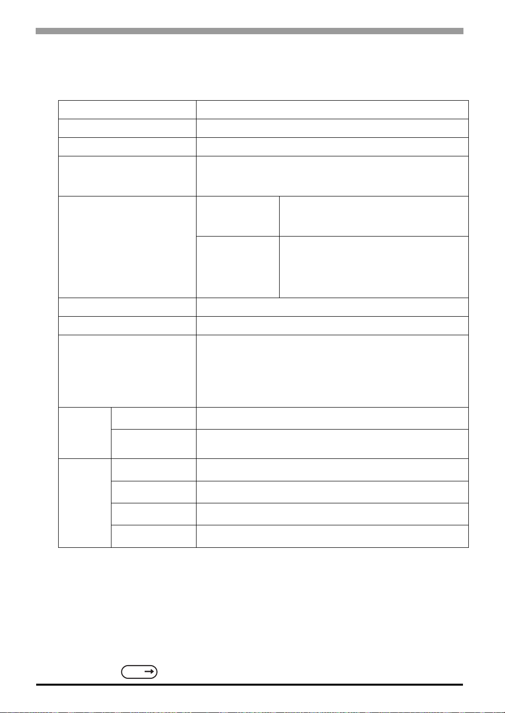
2.2 Functional Specifications
2.2.1 Display
Type Monochrome LCD
Resolution 320 x 240 pixels
Active Display Area W76.7 mm [3 .02in.] x H57.5 mm [2.26in.]
Black and White, 2 levels of gray/Black and White, 8 levels of
Colors
*1
gray
(Color switching is done via software)
ST400-AG41-24V
ST401-AG41-24V
ST402-AG41-24V
Backlight
ST403-AG41-24V
LED Backlight
(Color: Amber
*2
; Service life: Ave. 50,000 hrs.
[half of original brightness])
LED Backlight
(Color: Amber
[half of original brightness])
(Color: Red
*2
; Service life: Ave. 50,000 hrs.
*2
; Service life: Ave. 10,000 hrs.
[half of original brightness])
Contrast Adjustment 8 levels of adjustment available via touch panel.
Brightness Adjustment 2 levels of adjustment available via touch panel.
ASCII: (Code page 850) Alphanumeric (incl. Eur. characters)
Chinese: (GB2312-80 codes) simplified Chinese fonts
Language Fonts
Japanese: ANK 158, Kanji : 6,962 (JIS Standards 1 & 2)
(including 607 non-kanji characters)
Korean: (KSC5601 - 1992 codes) Hangul fonts
Taiwanese: (Big 5 codes) traditional Chinese fonts
Character Sizes
Character
Font Sizes
*3
8X8, 8X16, 16X16 and 32X32 dot fonts
Width can be expanded 1 to 8 times.
Height can be expanded 1/2 and 1 to 8 times.
8x8 dots 40 Char. x 30 rows
2-4
Text
8x16 dots 40 Char. x 15 rows
16x16 dots 20 Char. x15 rows
32x32 dots 10 Char. x 7 rows
*1 Depending on the color used, selecting MONOCHROME 8 HUES may cause the ST unit's screen
to flicker and make it difficult to distinguish colors. Confirm that all colors display as expected prior
to using this mode.
*2 Among backlight units there may be slight variations in illumination color, however, this does not
effect the performance or quality of the ST unit.
*3 The display font will differ depending on which (language) character, or which size you select. Also,
if GP-PRO/PBIII Ver. 5.0 or later software is used, high quality fonts are available with 16x16 or
larger characters.
SEE
6.9 Font Setting (Page 6-30)
Page 32
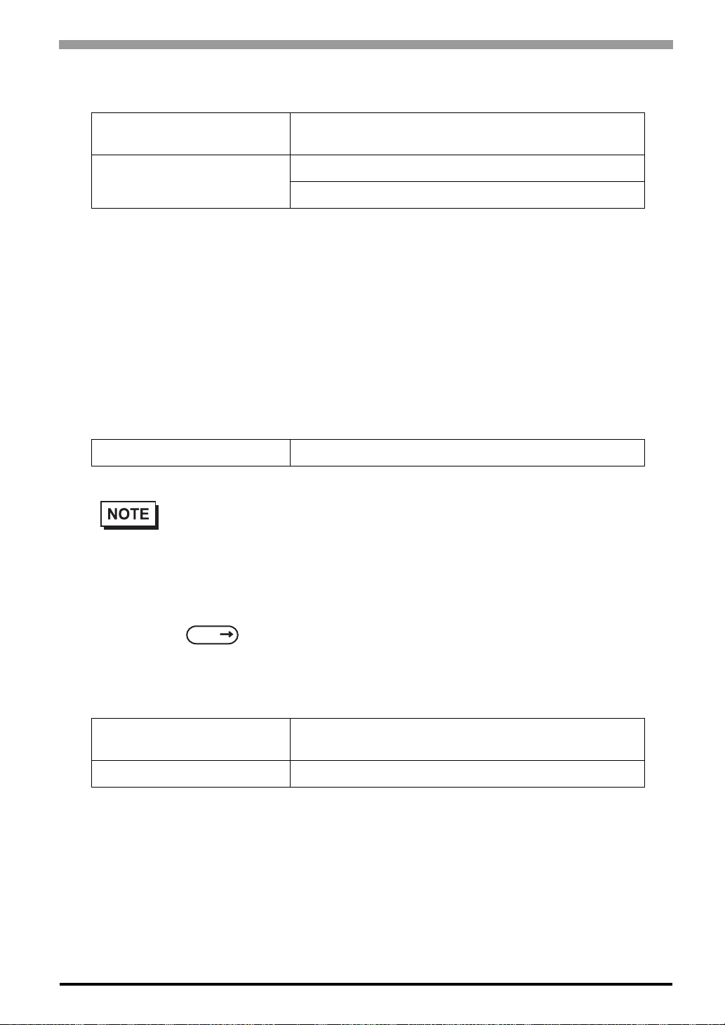
2.2.2 Memory
Chapter 2 Specifications
Application
Data Backup
*1 A Lithium battery's lifetime is:
10 years when the battery's ambient temperature is 40°C or less.
10 years when the unit's abmbient temperature is 25°C or less.
When used for backup:(without main power)
Approximately 60 days, with a fully charged battery
Approximately 6 days, with a 10% charged battery
User screen area: 640KB
Approx. 200 screens at 3.2KB/screen
96KB User backup memory
Uses a rechargeable lithium battery
2.2.3 Touch Panel and Clock
Clock Accuracy ±65 seconds/ month (at room temperature)
• The ST's internal clock has a slight error. At normal operating temperatures and conditions, with
*1
the ST operating from its lithium battery, the degree of error is 65 seconds per mon th. Variations
in operating conditions and battery life can cause this error to vary from -380 to +90 seconds per
month. For systems where this degree of error will be a problem, the user should be sure to monitor this error and make adjustments when required.
6.7 Set Up Time (Page 6-28)
SEE
2.2.4 Touch Panel and Function keys
Touch Panel Resolution
Function keys Switches: 6
8 x 6 keys/screen
1 or 2 point push - selectable
2-5
Page 33
ST Series User’s Manual
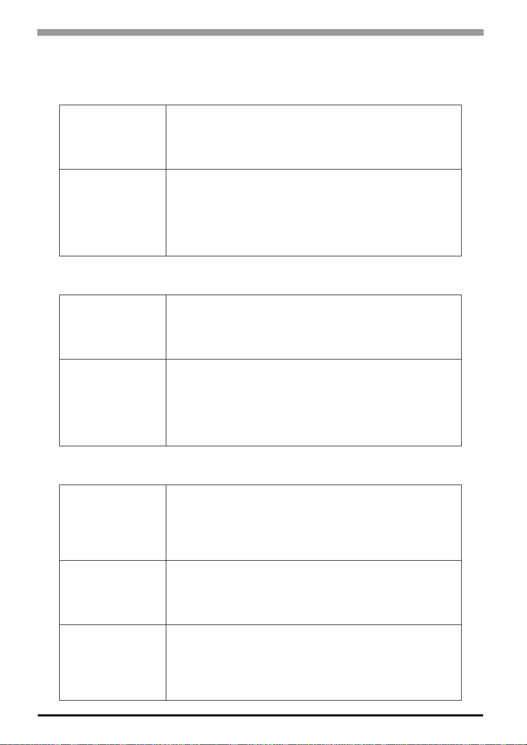
2.2.5 Interfaces ST400-AG41-24V
Serial I/F (X)
Tool Connector (TOOL)
ST401-AG41-24V
Serial I/F(Y)
Asynchronous Transmission : RS-422 (4-wire or 2-wire)
Data Length: 7 or 8 bits
Stop Bit: 1 or 2 bits
Parity: None, Odd or Even
Data Transmission Speed: 2,400bps to 115,200bps
Asynchronous TTL level nonprocedural command I/F
<During screen file development>
Used for transferring data to and from the GP application software and
the ST.
<During Operation>
Used for data transfer with the Internal 2-Port feature.
Used for a variety of devices, including a bar-code reader.
Asynchronous Transmission : RS-232C
Data Length: 7 or 8 bits
Stop Bit: 1 or 2 bits
Parity: None, Odd or Even
Data Transmission Speed: 2,400bps to 115,200bps
Tool Connector (TOOL)
ST402-AG41-24V
Serial Interface (X)
Expansion Serial Interface (Y)
Tool Connector (TOOL)
Asynchronous TTL level nonprocedural command I/F
<During screen file development>
Used for transferring data to and from the GP application software and
the ST.
<During Operation>
Used for data transfer with the Internal 2-Port feature.
Used for a variety of devices, including a bar-code reader.
Asynchronous Transmission : RS-485 (Siemens MPI Direct Connection )
Data Length: 7 or 8 bits
Stop Bit: 1 or 2 bits
Parity: None, Odd or Even
Data Transmission Speed: 2,400bps to 187.5Kbps
Asynchronous Transmission: RS-422 (4-wire or 2-wire)
Data Length: 7 or 8 bits
Stop Bit: 1 or 2 bits
Parity: None, Odd or Even
Data Transmission Speed: 2,400bps to 38,400bps
Asynchronous TTL level nonprocedural command I/F
<During screen file development>
Used for transferring data to and from the GP application software and
the ST.
<During Operation>
Used for a variety of devices, including a bar-code reader.
2-6
Page 34
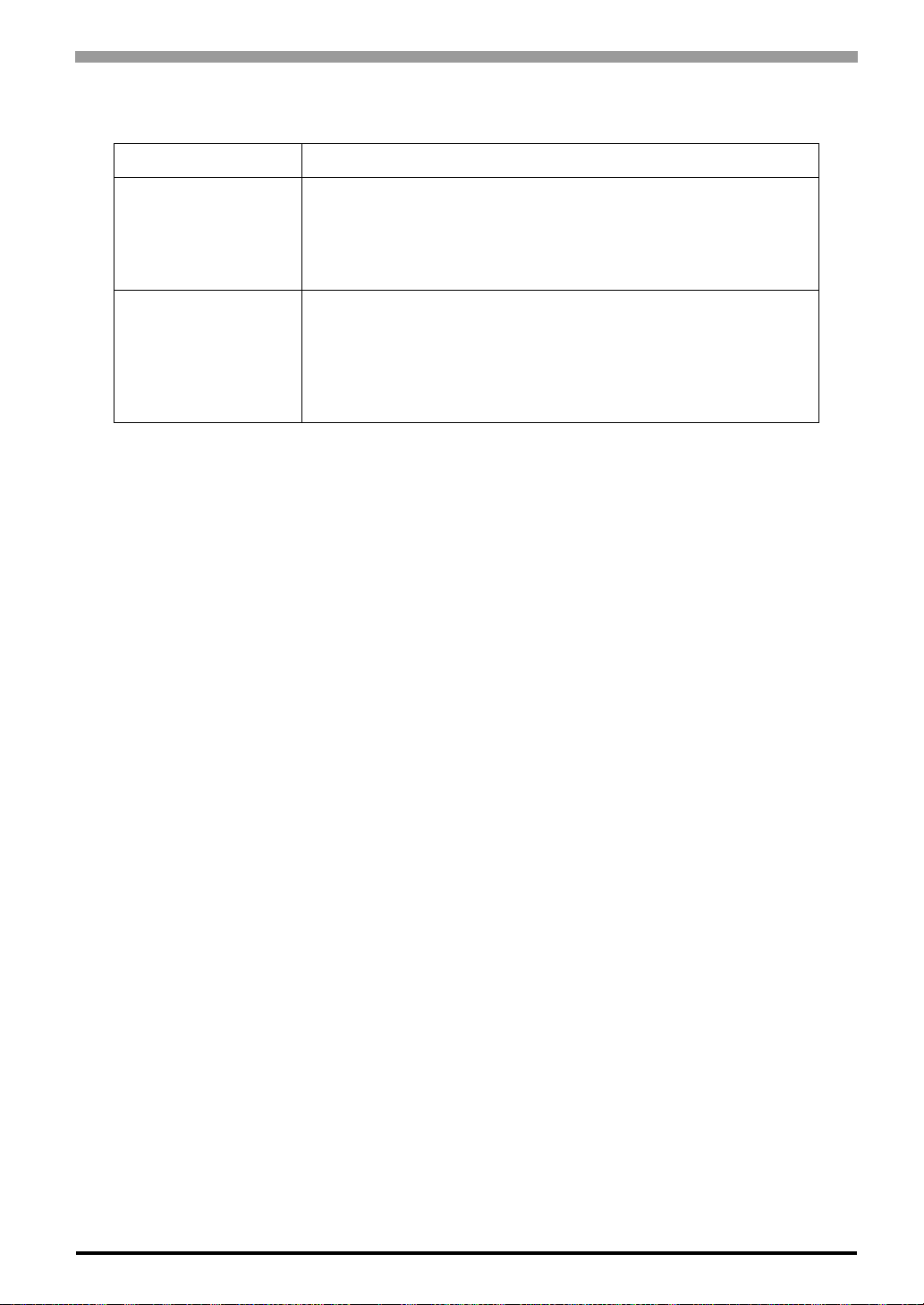
ST403-AG41-24V
Network Interface (X) Ethernet(IEEE802.3) 10BASE-T
Asynchronous Transmission: RS-232C/RS-422
Data Length: 7 or 8 bits
Serial I/F(Y)
Tool Connector (TOOL)
Stop Bit: 1 or 2 bi ts
Parity: None, Odd or Even
Data Transmission Speed: 2,400bps to 115,200bps
Asynchronous TTL level nonprocedural command I/F
<During screen file development>
Used for transferring data to and from the GP application software and
the ST.
<During Operation>
Used for a variety of devices, including a bar-code reader.
Chapter 2 Specifications
2-7
Page 35
ST Series User’s Manual
2.3 Interface Specifications
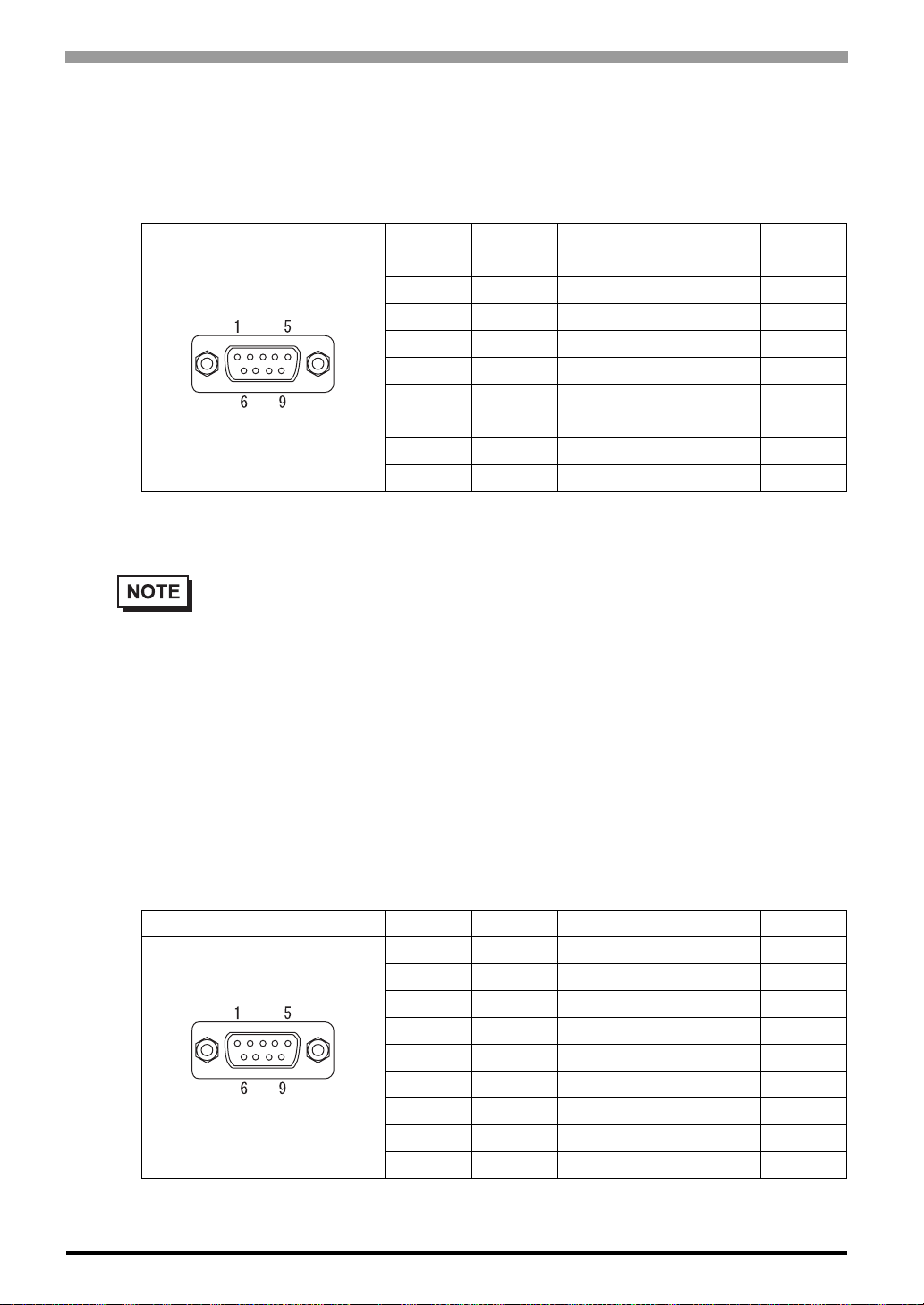
2.3.1 ST400-AG41-24V Serial Interface
RS-422 Interface (X)
Pin Connection Pin No. Signal Signal Name Direction
Recommended Connector : Dsub 9 pin socket-type XM2D-0901 <made by OMRON Corp.>
Recommended Cover : Dsub 9 pin cover XM2S-0913 <made by OMRON Corp.>
1 RDA Receive data A Input
2 RDB Receive data B Input
3 SDA Send data A Output
4 ERA Enable receive A Output
5 SG Ground 6 CSB Clear send B Input
7 SDB Send data B Output
8 CSA Clear send A Input
9 ERB Enable receive B Output
• RS-422 (4-wire or 2-wire) can be used to connect the ST with Devices/PLCs.
• Use inch type screw (#4-40UNC) as set screws.
• The following pairs of pin #’s must be connected to each other.
#6(CSB) <-> #9(ERB)
#8(CSA) <-> #4(ERA)
• This unit is not equipped internally with termination resistance. Attach termination resistan ce to
the cable. If there is no designation on the PLC/Device side, attach 100Ω1/2W.
2.3.2 ST401-AG41-24V Serial Interface
RS-232C Interface (Y)
Pin Connection Pin No. Signal Signal Name Direction
1 CD Carrier detect Input
2 RD Receive data Input
3 SD Send data Output
4 ER Enable receive Output
5 SG Ground 6 DR Data set ready Input
7 RS Request send Output
8 CS Clear send Input
9 RI Ring indicate Input
2-8
Recommended Connector : Dsub 9 pin socket-type XM2D-0901 <made by OMRON Corp.>
Recommended Cover : Dsub 9 pin cover XM2S-0913 <made by OMRON Corp.>
Page 36
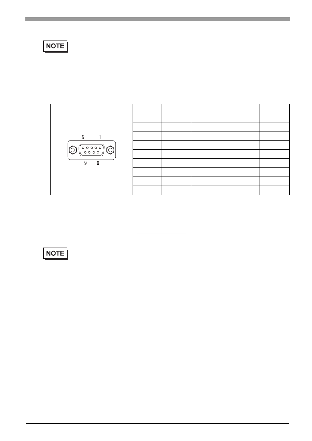
• RS-232C can be used to connect the ST with Devices/PLCs.
• Use inch type screw (#4-40UNC) as set screws.
2.3.3 ST402-AG41-24V Serial Interface
RS-485 (MPI) Interface (X)
Pin Connection Pin No. Signal Signal Name Direction
*1
*1 The connector of the ST side is socket type.
Chapter 2 Specifications
1 NC No connection 2 NC No connection 3 LINE(+) Line (+) In/Output
4 RTS Request Send Output
5 SG Ground 6 5V 5V External Output
7 NC No connection 8 LINE(-) Line (-) In/Output
9 NC No connection -
*2
Output
*2 When providing power via the Seimens Corporation Profibus connector, power cannot be
connected to the Device/PLC.
Recommended Connector : Dsub 9 pin pin-type XM2A-0901
Recommended Cover : Dsub 9 pin cover XM2S-0913 <made by OMRON Corp.>
• This communication port is designed exclusively to be used for an MPI Direct Connection with
Seimens Corporation S7-200/300/400 Series PLCs.
• Use inch type screw (#4-40UNC) as set screws.
• This unit is not equipped internally with termination resistance. Attach termi nation resistance to
the cable. If there is no designation on the PLC side, attach 100Ω1/2W.
<made by OMRON Corp.>
2-9
Page 37
ST Series User’s Manual
Expansion Serial Interface
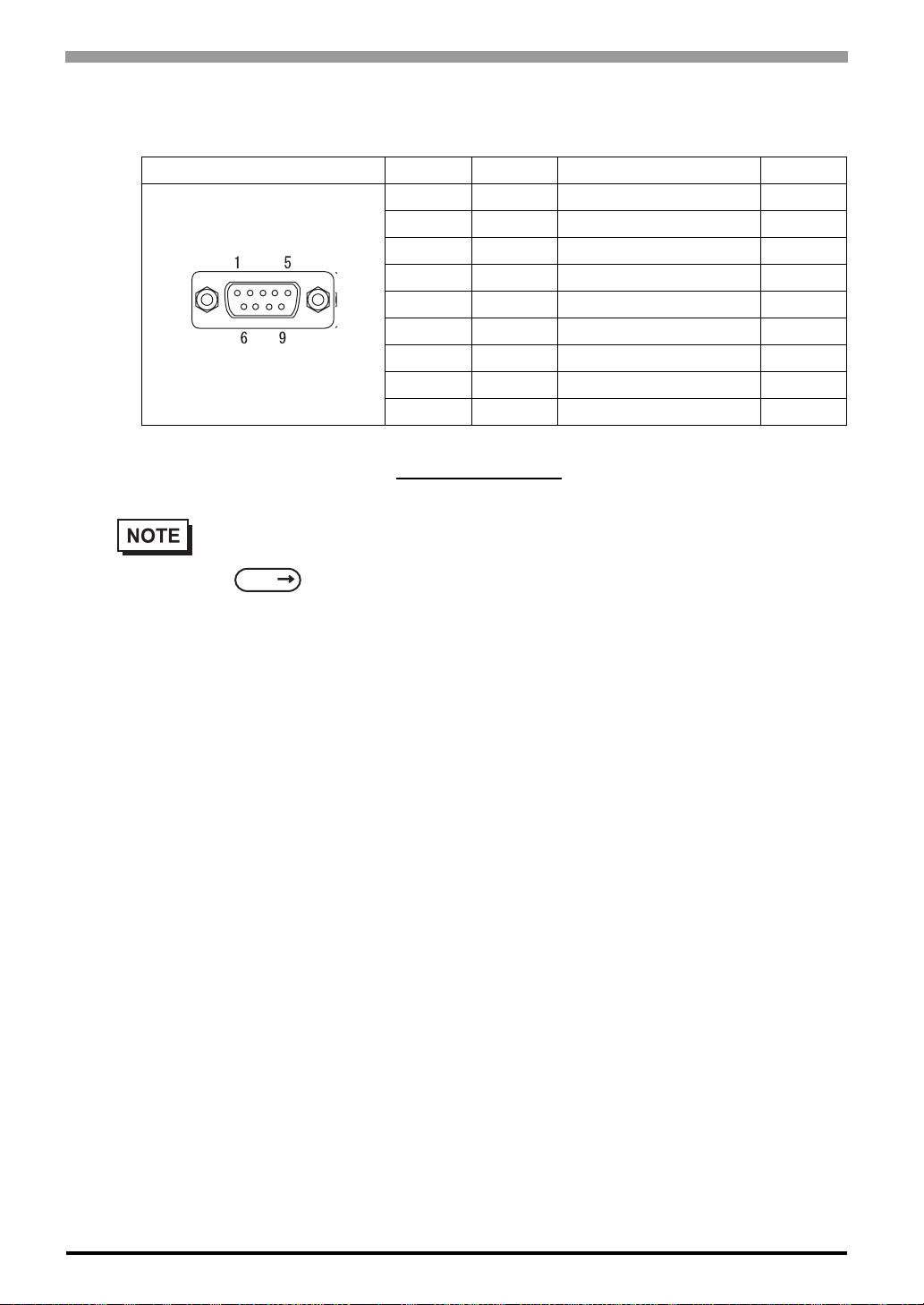
RS-422 Interface (Y)
Pin Connection Pin No. Signal Signal Name Direction
*1 The connector of the ST side is pin type.
Recommended Connector : Dsub 9 pin socket-type XM2D-0901 <made by OMRON Corp.>
Recommended Cover : Dsub 9 pin cover XM2S-0913 <made by OMRON Corp.>
• This communication port is used exclusively for Extended SIO Scripts. To use this port, an
Extended SIO Script is required.
SEE
screen editor software)
• Use inch type screw (#4-40UNC) as set screws.
1 RDA Receive data A Input
2 RDB Receive data B Input
3 SDA Send data A Output
4 ERA Enable receive A Output
5 SG Ground 6 CSB Clear send B Input
7 SDB Send data B Output
*1
GP-PRO/PBIII for Windows Device/PLC Connection Manu al (included with the
8 CSA Clear send A Input
9 ERB Enable receive B Output
• The following pairs of pin #’s must be connected to each other.
#6(CSB) <-> #9(ERB)
#8(CSA) <-> #4(ERA)
• This unit is not equipped internally with termination resistance. Attach termination resistan ce to
the cable. If there is no designation on the PLC/Device side, attach 100Ω1/2W.
2-10
Page 38
2.3.4 ST403-AG41-24V
Chapter 2 Specifications
Ethernet Interface
This is the Ethernet Interface of 10 BASE-T. LED lights up or blinks according to the status.
LED Contents
Orange
Green When linking, LED lights up.
(X)
When the power supply is on, LED lights up.
When sending or receiving, LED blinks.
Serial Interface
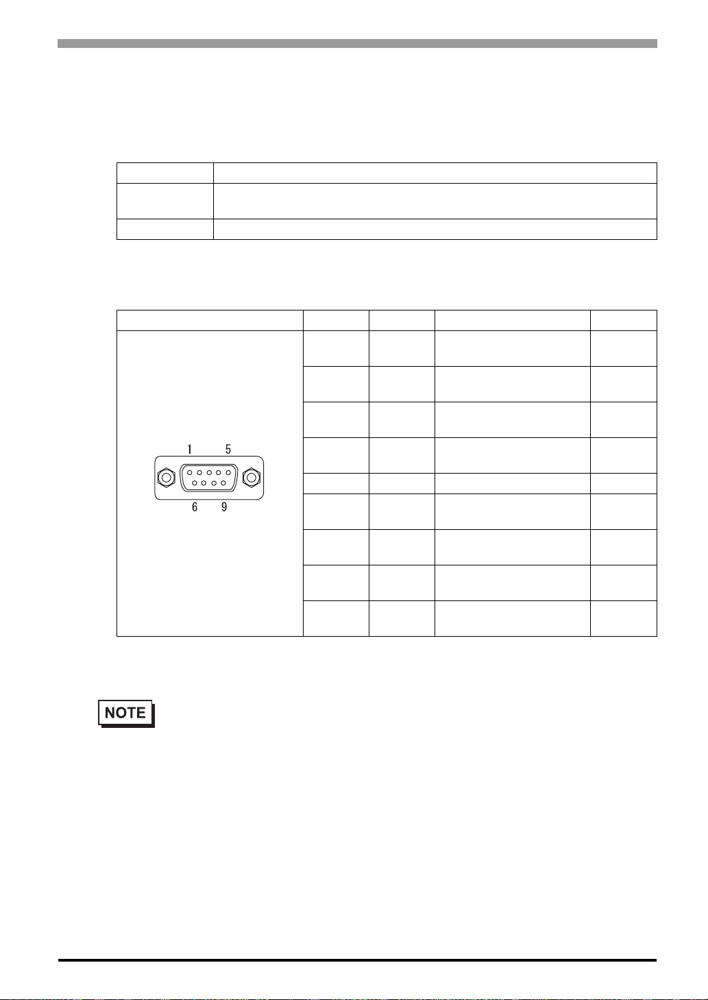
RS-232C/RS-422 Interface (Y)
Pin Connection Pin No. Signal Signal Name Direction
*1
1 CD/RDA
2 RD/RDB
3 SD/SDA Send data/Send data A
4ER/ERA
5 SG/SG Ground/Ground 6 DR/CSB
7RS/SDB
8 CS/CSA Clear send/Clear send A
9RI/ERB
Carrier detect
/Receive data A
Receive data
/Receive data B
Enable receive
/Enable receive A
Data set ready/Clear
send B
Request send
/Send data B
Ring indicate
/Enable receive B
Input
/Inpu
Input
/Input
Output
/Output
Output
/Output
Input
/Input
Output
/Output
Input
/Input
Input
/Output
Recommended Connector : Dsub 9 pin socket-type XM2D-0901 <made by OMRON Corp.>
Recommended Cover : Dsub 9 pin cover XM2S-0913 <made by OMRON Corp.>
• Use inch type screw (#4-40UNC) as set screws.
• RS-422 is not equipped internally with termination resistance. Attach termination resistance to
the cable.
*1 Transmission method is used by changing in the screen editor software or in the setting at the ST unit.
2-11
Page 39
ST Series User’s Manual
F1
F2
F3
F4
F5
F6
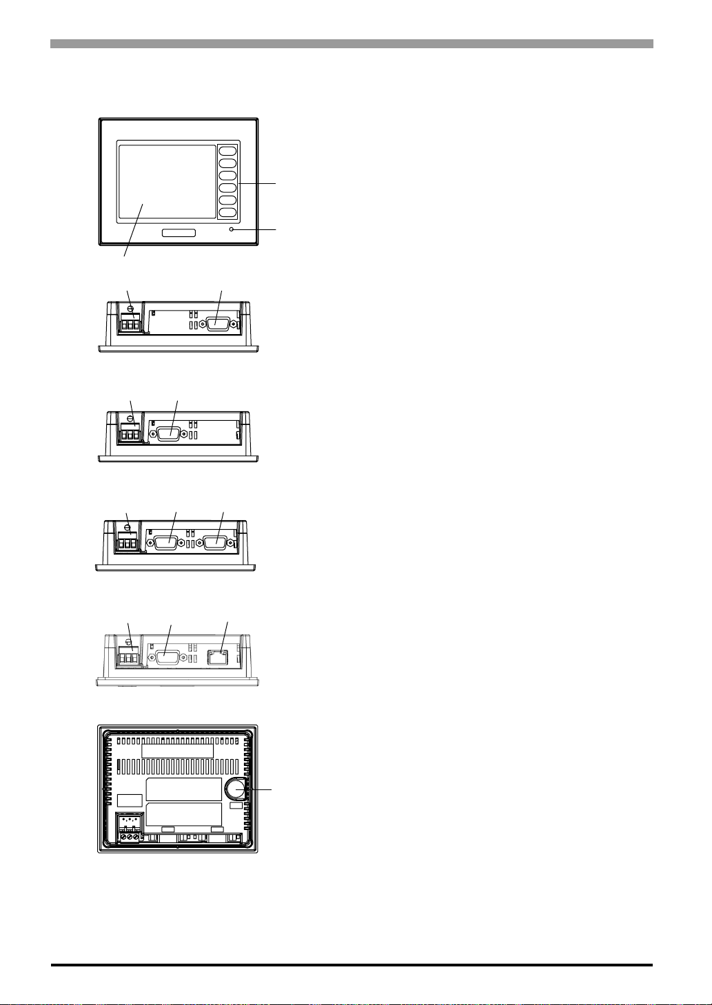
2.4 Part Names and Functions
A: Display
F1
F2
F3
F4
F5
F6
A, B
Front
E
F
ST400-AG41-24V Bottom
E
G
ST401-AG41-24V Bottom
E
I H
B: Touch Panel
C
C: Function Switch (F1 to F6)
D: Power Lamp
D
E: Power Plug
F: RS-422 Interface (X)
G: RS-232C Interface (Y)
H: RS-485(MPI) Interface (X)
I: RS-422 Interface (Y)
J:Ethernet Interface (X)
K:RS-232C/RS-422 Interface (Y)
L: Tool Connector (TOOL)
2-12
ST402-AG41-24V Bottom
E
K
J
ST403-AG41-24V Bottom
Rear
L
Page 40
2.5 Dimensions
118[4.65]
Top
Front
Right Side
104[4.09]
5[0.20]
41[1.61]
Unit:mm[in.]
130[5.12]
92[3.62]
F1
F2
F3
F4
F5
F6
F1
F2
F3
F4
F5
F6
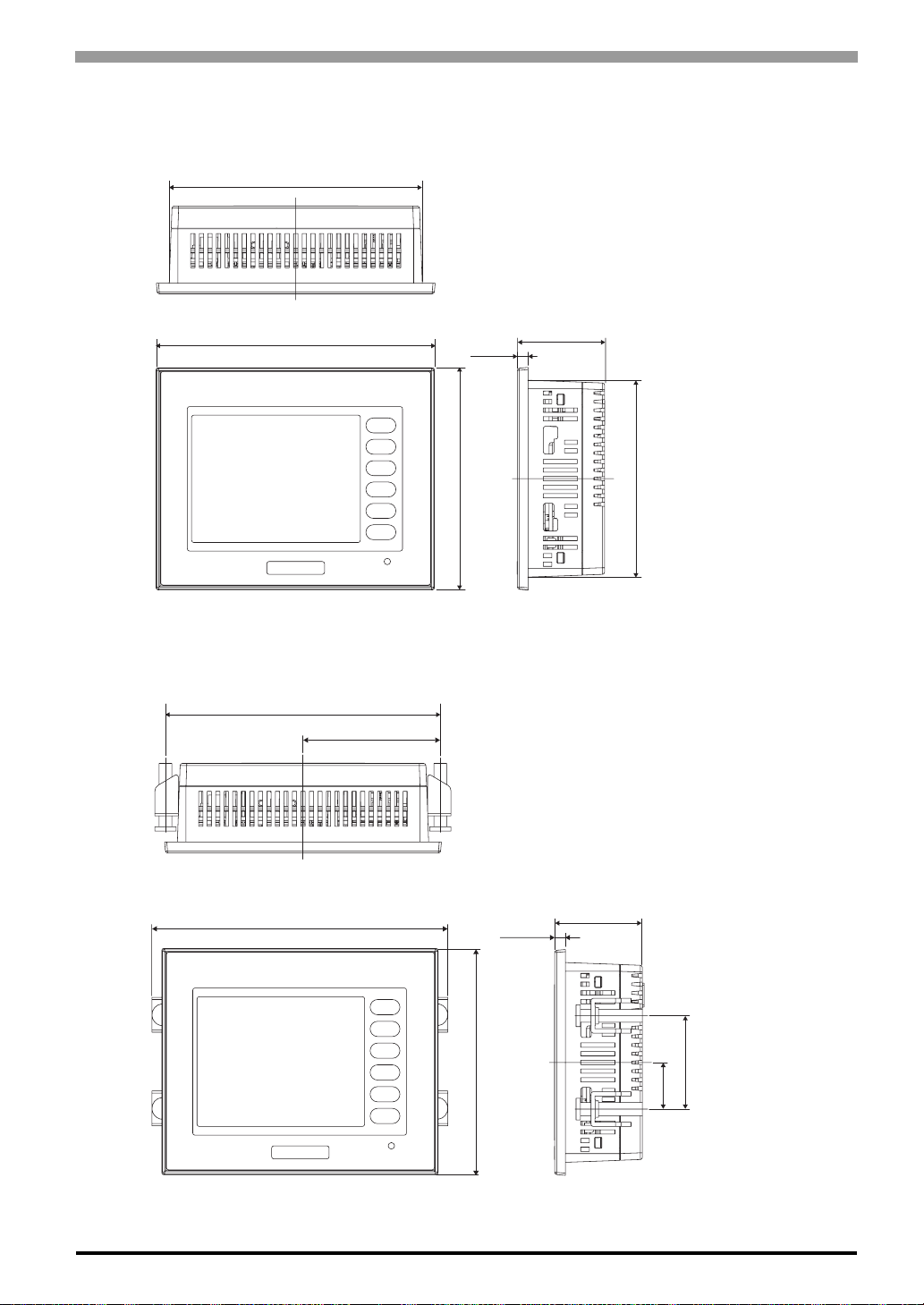
2.5.1 ST Series External Dimensions
118[4.65]
Chapter 2 Specifications
Unit:mm[in.]
Top
130[5.12]
Front
5[0.20]
F1
F2
F3
F4
F5
F6
104[4.09]
41[1.61]
Right Side
The following drawing shows the ST Series unit with installation fasteners.
129[5.08]
64.5[2.54]
Unit:mm[in.]
92[3.62]
F1
F2
F3
F4
F5
F6
104[4.09]
5[0.20]
41[1.61]
43[1.69]
21.5[0.85]
Right Side
Top
139[5.47]
Front
2-13
Page 41
ST Series User’s Manual
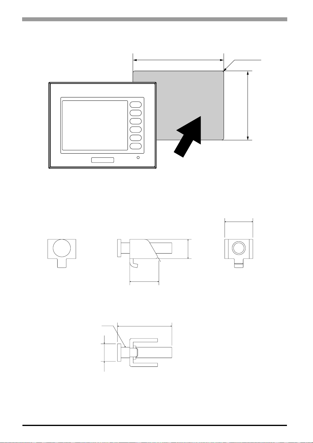
2.5.2 Panel Cut Dimensions
Unit: mm [in.]
118.5
+1
+0.04
[4.67
0
]
0
Under 4-R3
]
0 0
+1
2.5.3 Installation Fasteners
Unit:mm[in]
F1
F2
F3
F4
F5
F6
16.6[0.65]
11
[3.64
+1
92.5
16[0.63]
[0.43]
2-14
M6
φ10
31[1.22]
[0.39]
Page 42

3
Installation and Wiring
3.1 Installation
3.2 Wiring Precautions
3.3 Tool Connector
3.4 Ethernet Cable Connector
3-1
Page 43
ST Series User’s Manual
3.1 Installation
3.1.1 Installation Procedures
Follow the steps given below when installing the ST.
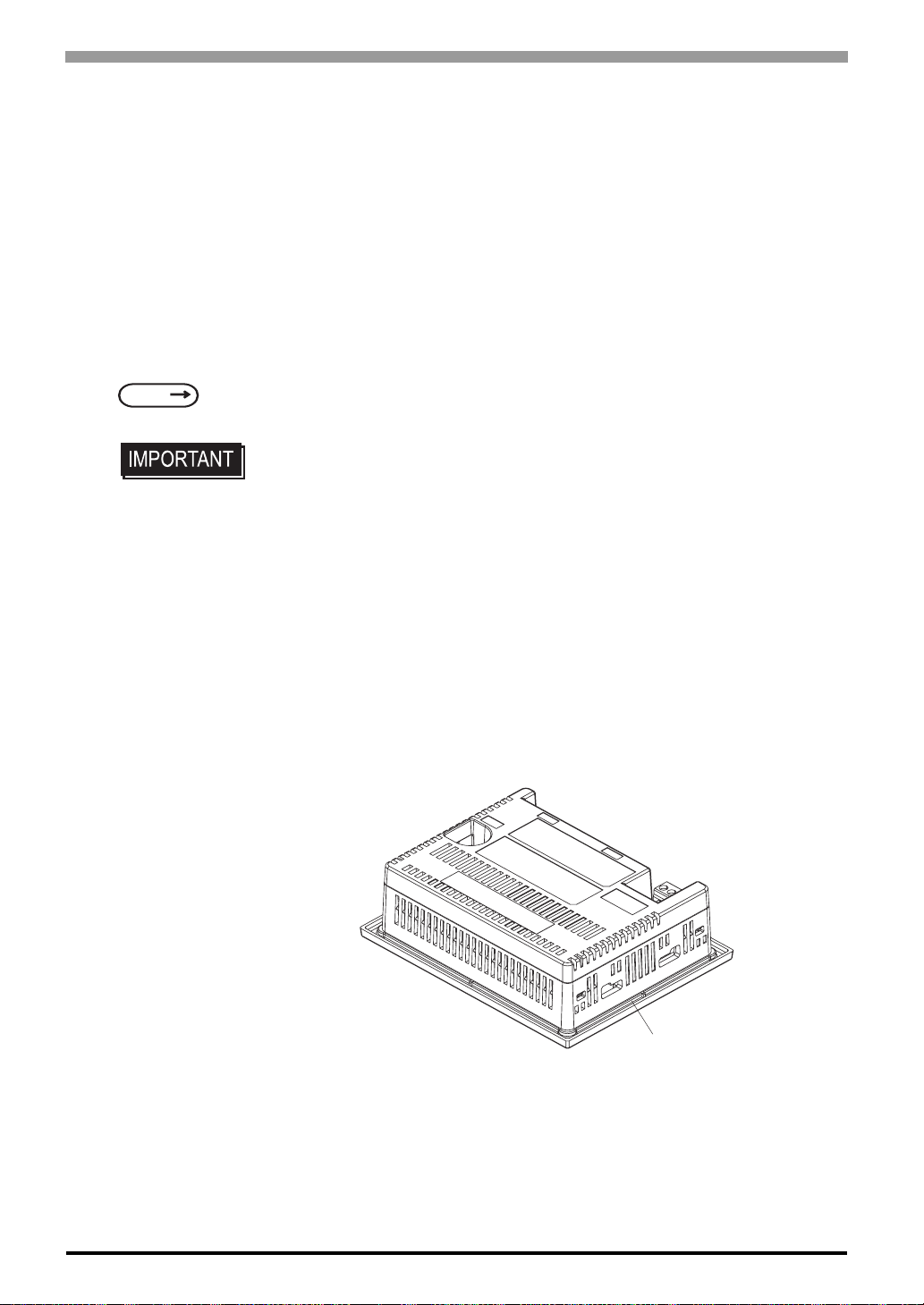
Check the Installation Gasket’s Seating
It is strongly recommended that you use the installation gasket, since it absorbs vibration in addition to
repelling water.
Place the ST on a level surface with the display panel facing downward. Check that the
ST’s installation gasket is seated securely into the gasket’s groove, which runs around the perimeter of the
panel’s frame. For details about installing the gasket, refer to
SEE
8.1.2 Installation Gasket Check/Replacement (Page 8-2)
• Before installing the ST into a cabinet or panel, check that the installation
gasket is securely attached to the unit.
• A gasket which has been used for a long period of time may have scraches or dirt
on it, and could have lost much of its dust and drip resistance. Be sure to change
the gasket periodically (or when scratches or dirt become visible).
• Be sure to use gasket model ST400-WP01
• Be sure the gasket's seam is not inserted into any of the unit's corners, only in
the straight sections of the groove. Inserting it into a corner may lead to its eventually tearing.
• To ensure the installation gasket’s maximum level of moisture resistance, be
sure the gasket's seam instead as shown into the panel's bottom face.
3-2
Rear face of ST
Installation
Gasket
Page 44
Chapter 3 Installation and Wiring
F1
F2
F3
F4
F5
F6
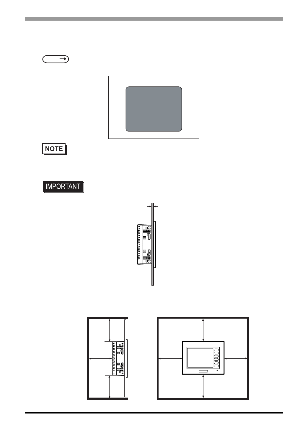
Creating a Panel Cut
Create the correct sized opening required to install the ST, using the installation dimensions given.
SEE
2.5.2 Panel Cut Dimensions (Page 2-14)
The installation gasket, installation brackets and attachment screws are all required when installing the ST .
Panel
Panel Cut
Area
• Check that the installation panel or cabinet's surface is flat, in good condition and has no jagged
edges. Also, if desired, metal reinforcing strips can be attached to the inside of the panel, near
the Panel Cut, to increase the panel’s strength.
• Panel thickness should be from 1.6mm [0.06in.] to 10mm [0.4in.]. Decide the
panel's thickness based on the level of panel strength required.
1.6mm[0.06in.]
to 5.0mm[0.2in.]
• For easier maintenance, operation, and improved ventilation, be sure to install the
ST at least 100 mm [3.94 in.] away from adjacent structures and other equipment.
Unit: mm [in.]
100
100 [3.94]
[3.94]
100
[3.94]
100
[3.94]
100
[3.94]
F1
F2
F3
F4
F5
F6
100 [3.94]
100
[3.94]
3-3
Page 45
ST Series User’s Manual
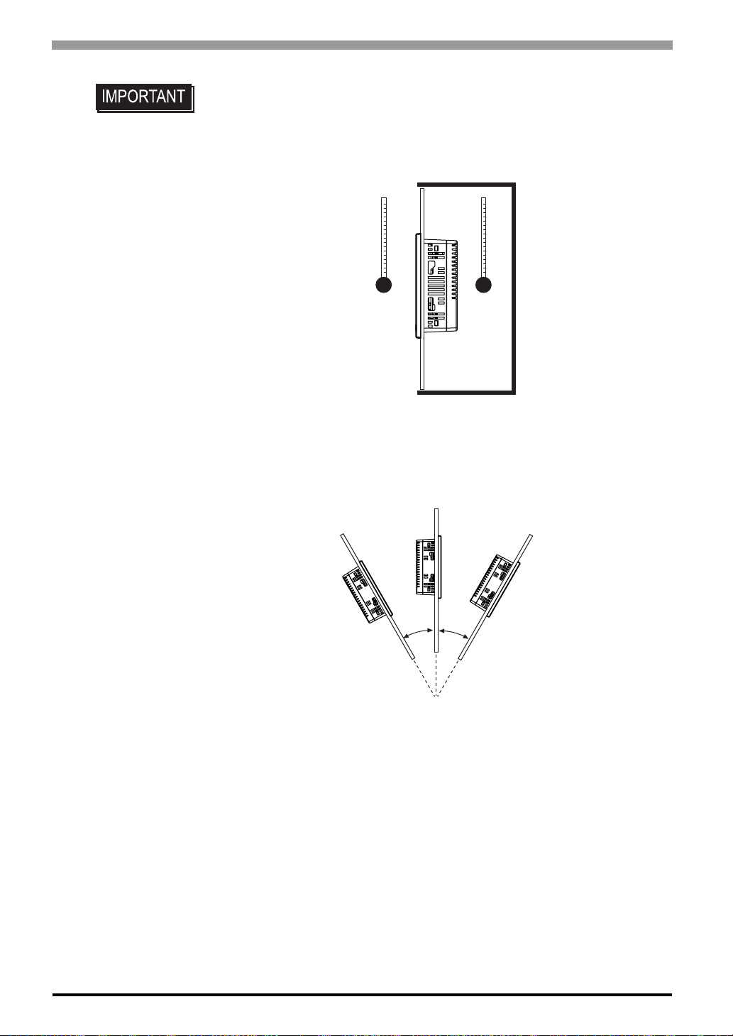
• Be sure that the ambient operation temperature and the ambient humidity are
within their designated ranges. (When installing the ST in a cabinet or enclosure,
the term “ambient operation temperature” indicates the cabinet or enclosureís
internal temperature.
Outside
Cabinet
• Be sure that heat from surrounding equipment does not cause the ST to exceed
its standard operating temperature.
• When installing the ST in a slanted panel, the panel face should not incline more
than 30°.
Inside
Cabinet
o
30
or less
3-4
• When installing the ST in a slanted panel, and the panel face inclines more than
30°, the ambient temperature must not exceed 40°C.
• When installing the ST vertically, position the unit so that the Power Input Terminal Block is also vertical.
Page 46
Chapter 3 Installation and Wiring
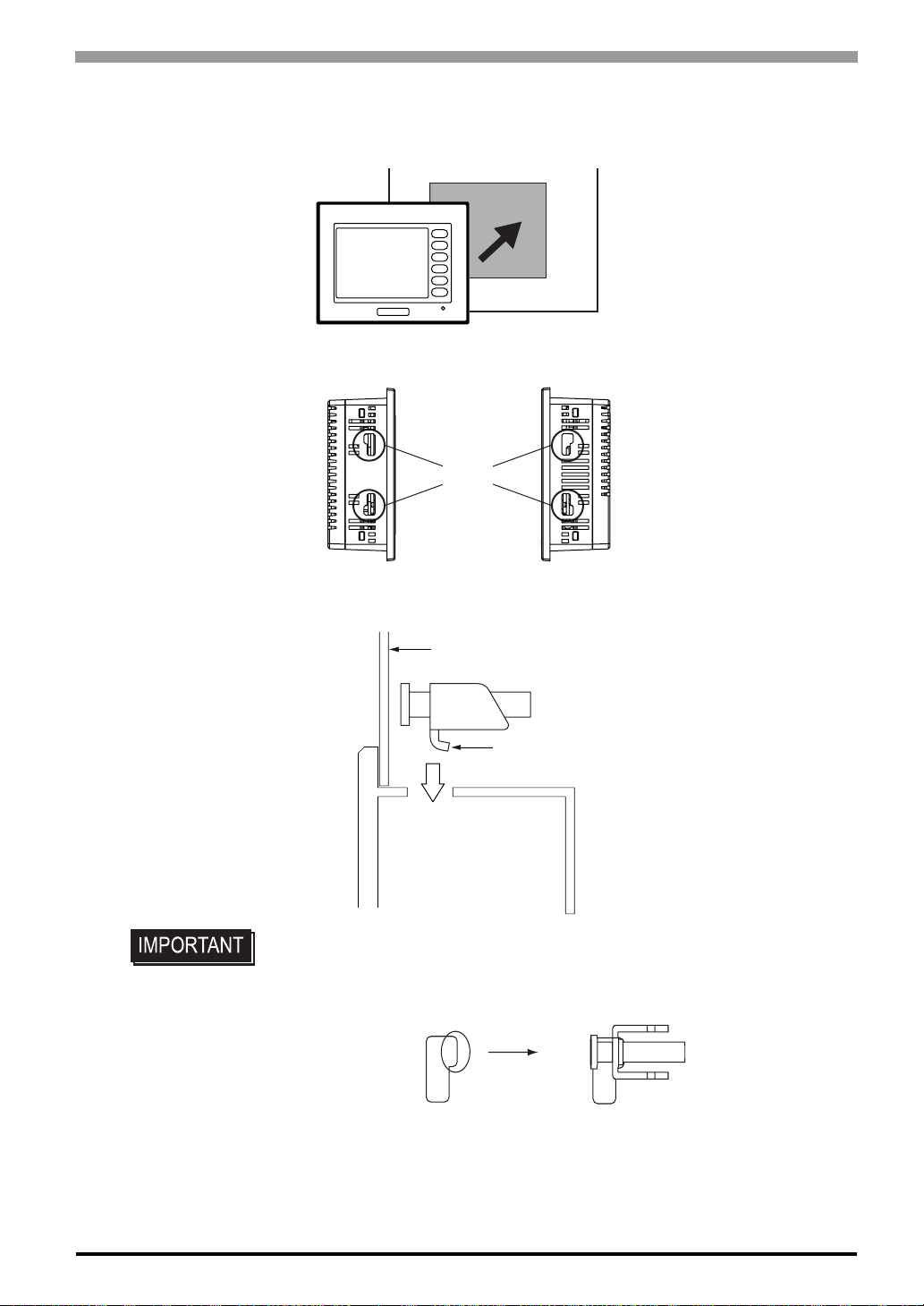
Installing the ST
(1) Insert the ST into the panel cut out, as shown here.
F1
F2
ST
(2) Insert the installation fasteners into the ST’s insertion slots, on the right and left side of the unit.
F3
F4
F5
F6
Slot
Installation panel
Hook
• Be sure to insert installation fasteners in the recessed portion of a installation fasteners hole. (Refer to the following figure) If the fasteners are not correctly
attached, the ST unit may shift or fall out of the panel.
3-5
Page 47
ST Series User’s Manual
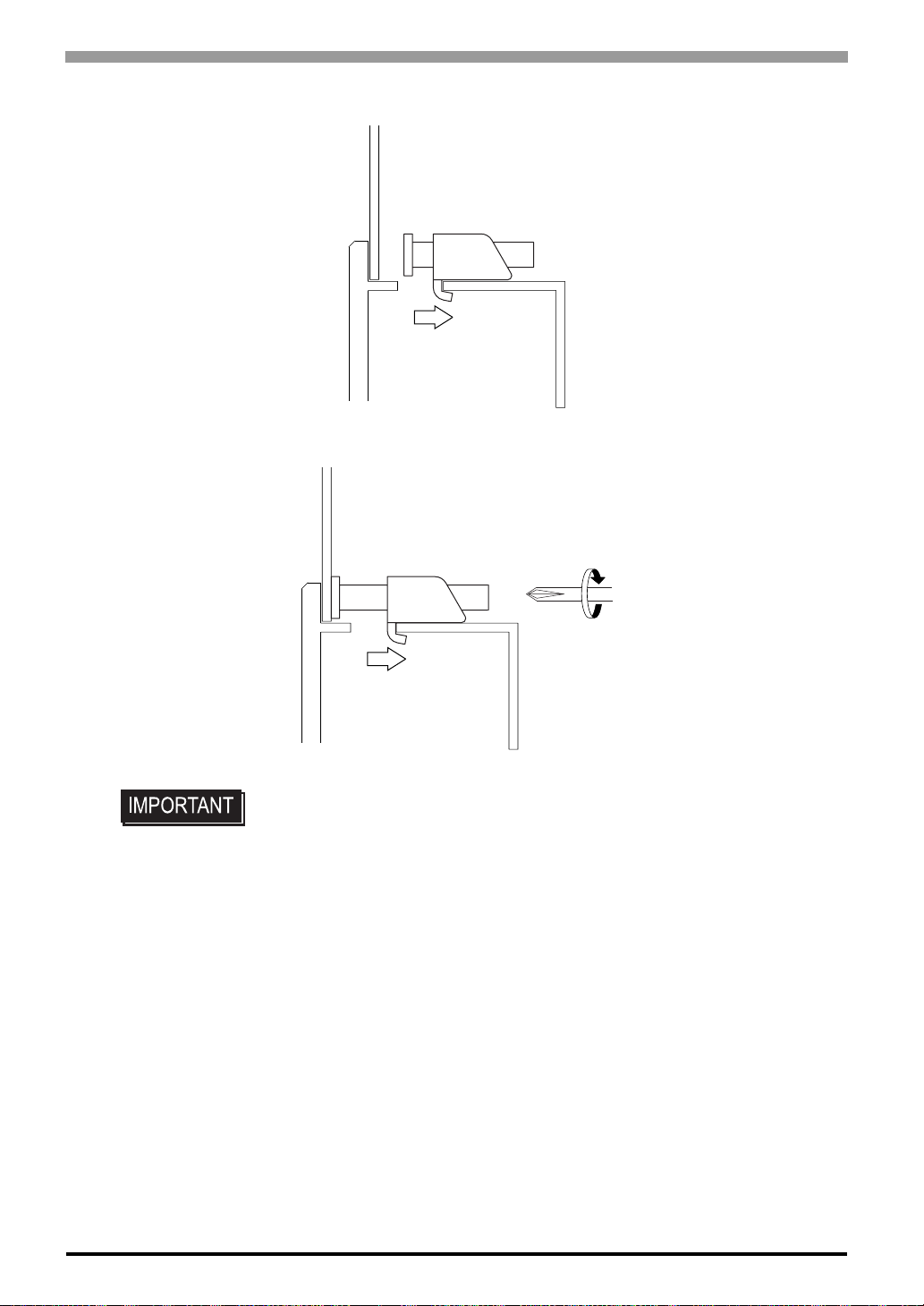
(3) Installation fasteners are made to slide to a back side.
(4) Use a Phillips screwdriver to tighten each fastener screw and secure the ST in place.
3-6
• A torque of only 0.5 Nïm is sufficient to tighten these screws. Do not use too
much force, since it may damage the ST unit.
Page 48
3.2 Wiring Precautions
3.2.1 Connecting the Power Cord
To avoid an electric shock, be sure the power cord is unplugged from the power outlet
when connecting the power terminals to the ST unit.
The ST400-AG41-24V, ST401-AG41-24V, ST402-AG41-24V and ST403-AG41-24V are
designed to use only DC24V power. Using any other level of power can damage both the
power supply and the ST unit.
Since the ST is not equipped with the power switch, be sure to connect a breaker type
power switch to the ST’s power cord.
Be sure to ground the ST's FG terminal. Failure to do so can lead to an electrical shock or
ST malfunction.
If the power cord is pulled strongly, the power plug may fall out.
Chapter 3 Installation and Wiring
• When the FG terminal is connected, be sure the wire is grounded. Not grounding
the ST unit will result in excessive noise. Use your country's applicable standard
for grounding.
SEE
• The SG and FG terminals are connected internally in the ST unit.
3.2.3 Grounding (Page 3-10)
Wiring
When connecting the Power Cord, Use the following items when performing wiring. (Items are
*1
made by Phoenix Contact.
Recommended Driver SZF 1-0.6x3.5 (1204517)
Recommended Pin Terminals
Recommended Pin
Terminal Crimp Tool
AI 0.25-6BU (3201291)
AI 0.34-8TQ (3200865)
AI 0.5-8WH (3200014)
AI 0.75-8GY (3200519)
AI 1-8RD (3200030)
AI 1.5-8BK (3200043)
AI 2.5-8BU (3200522)
CRIMPFOX ZA3 (1201882)
*1 For details, please contact your local Phoenix Contact distributor.
3-7
Page 49
ST Series User’s Manual
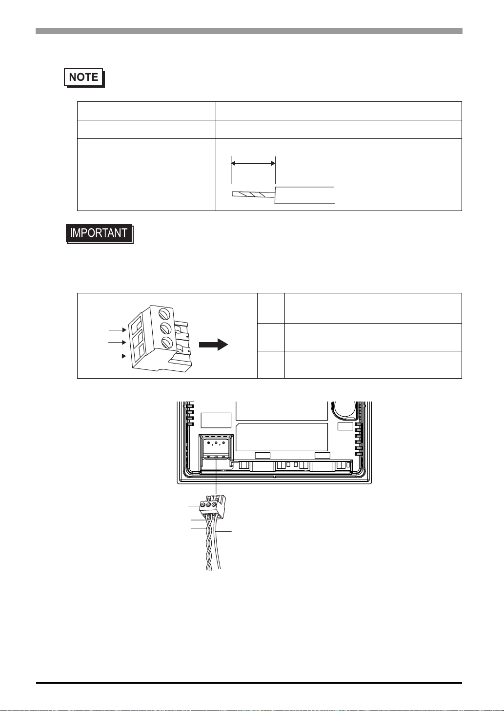
• Power Cord Specifications
Power Cord Diameter 0.2 to 2.5 mm2 (0.0001 to 0.0097 inch2) (24 to 12 AWG)
Conductor Type Simple or Twisted Wire
Conductor Length
• If the Conductor's end (individual) wires are not twisted correctly, the end wires
may either short against each other, or against an electrode.
Power Plug Specifications
7mm
+
-
FG
Terminal block
wire set screws
Insertion Direction
+
-
+24V
-0V
FG Grounding Terminal connected to the ST.
Rear face of ST
FG
3-8
(1) Be sure that the ST's power cord is not plugged in to the power supply.
(2) Remove the power plug form the ST unit.
(3) Insert each wire into the power plug’s wire hole.
(4) Replace th e power pl ug.
Page 50
• Use flat screwriver (SIZE 0.6 x 3.5) to tighten the terminal block wire set screws.
The torque required to tighten these screws is 0.5 to 0.6 Nïm.
• Do not solder the wire itself.
• The power supply cord should be equivalent to the specification shown above. Be sure to twist
the power cords together, up to the power plug. (See illustration as shown below)
• The power supply plug MSTB2,5/3-ST-5,08 is made by Phoenix Contact.
3.2.2 Connecting the Power Supply
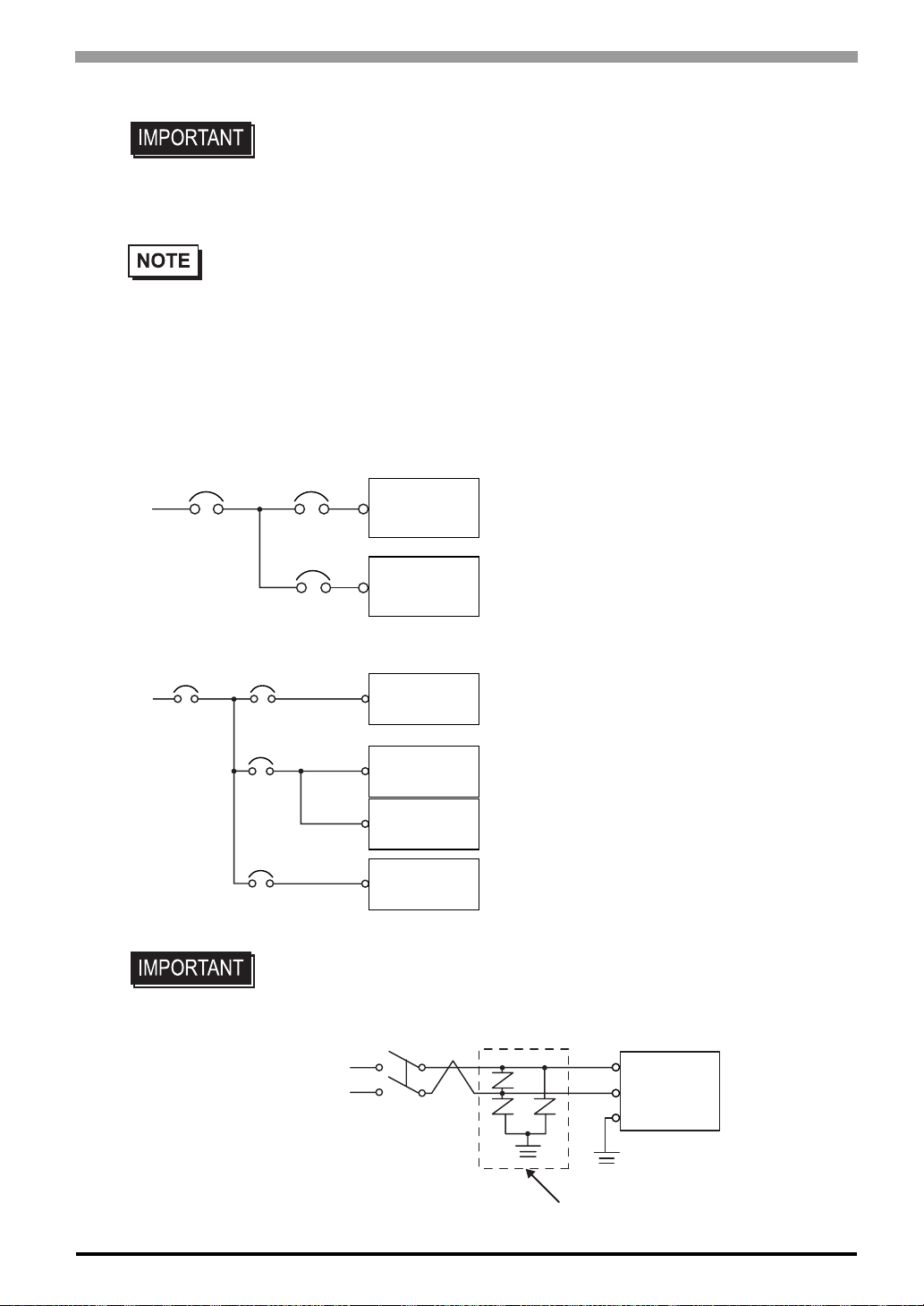
Notes when the power supply is supplied. Please connect the power cable with the power supply connector on
the main body side with a power plug of the attachment.
Chapter 3 Installation and Wiring
Main Power
Main
Power
ST Power
ST Power
ST Unit
• When supplying power to the ST unit, please
separate the input/output and operation unit
lines, as shown.
Power
Input/Outpt
Input/Outpt
Unit
• To increase the noise resistance quality of the
power cord, simply twist each power wire
before attaching the Ring Terminal.
• The power supp ly cord must not be bundled or
ST Unit
Power
Input/Outpt
Input/Outpt
Power
positioned close to main circuit lines (high voltage, high current), or input/output signal lines.
• Connect a lightning sur ge absorber , as shown in
the diagram, to deal with power surges.
Input/Outpt
Main Circuit
Motor
Power
Operation
Unit
•To avoid excess noise, make the power cord as
short as possible.
• Be sure to ground the surge absorber (E1) separately from the ST unit (E2).
• Select a surge absorber that has a maximum circuit voltage greater than that of
the peak voltage of the power supply.
E1
ST Unit
FG
E2
Lightning Surge Absorber
3-9
Page 51
ST Series User’s Manual
3.2.3 Grounding
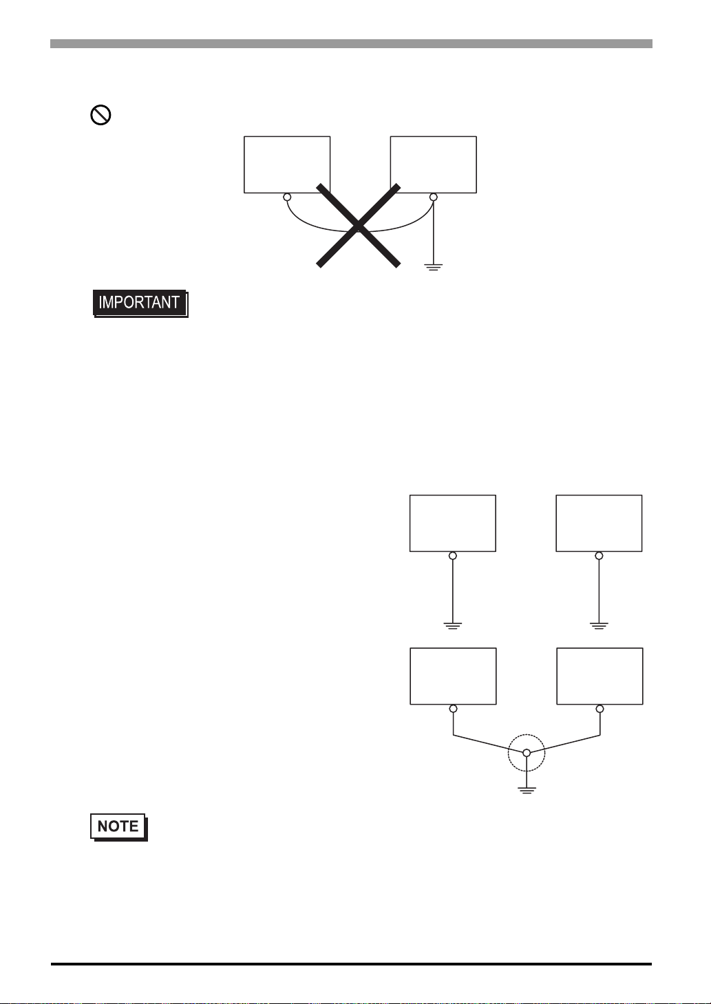
Do not use common grounding, since it can lead to an accident or machine breakdown.
ST Unit
• When connecting an FG ground wire to the Power Plug's FG terminal, be sure to
create an exclusive ground. Check that the grounding resistance is less than
100Ω.
• Inside the ST400-AG41-24V/ST401-AG41-24V/ST402-AG41-24V/ST403-AG4124V unit, the SG (Signal Ground) and FG (Frame Ground) terminal are connected to each other.
• When connecting the SG line to another device, be sure that the design of the
system/connection does not produce a shorting loop.
• The grounding wire should have a cross sectional area greater than 2mm
Create the connection point as close to the ST unit as possible, and make the
wire as short, as possible. When using a long grounding wire, replace the thin
wire with a thicker wire, and place it in a duct.
(a) Exclusive Grounding (BEST)
*1
• Connect the FG terminal found at the Power Plug to
an exclusive ground. [diagram (a)].
Other
Equipment
ST
2
Other
Equipment
.
3-10
(b) Common Grounding (OK)*1
• If exclusive grounding is not possible, use a commo n
connection point. [diagram (b)]
• If the equipment does not function properly when grounded, disconnect the ground wire from
the FG terminal.
*1 Use a grounding resistance of less than 100Ω and a 2mm
applicable standard. For details, contact your local GP distributor.
ST
2
or greater thickness wire, or your country’s
Other
Equipment
Page 52
Chapter 3 Installation and Wiring
3.2.4 I/O Signal Line Placement
• Input an d output signal lines must be separated from the power control cables for operating circuits.
• If this is not possible, use a shielded cable and connect the shield to the ST's frame.
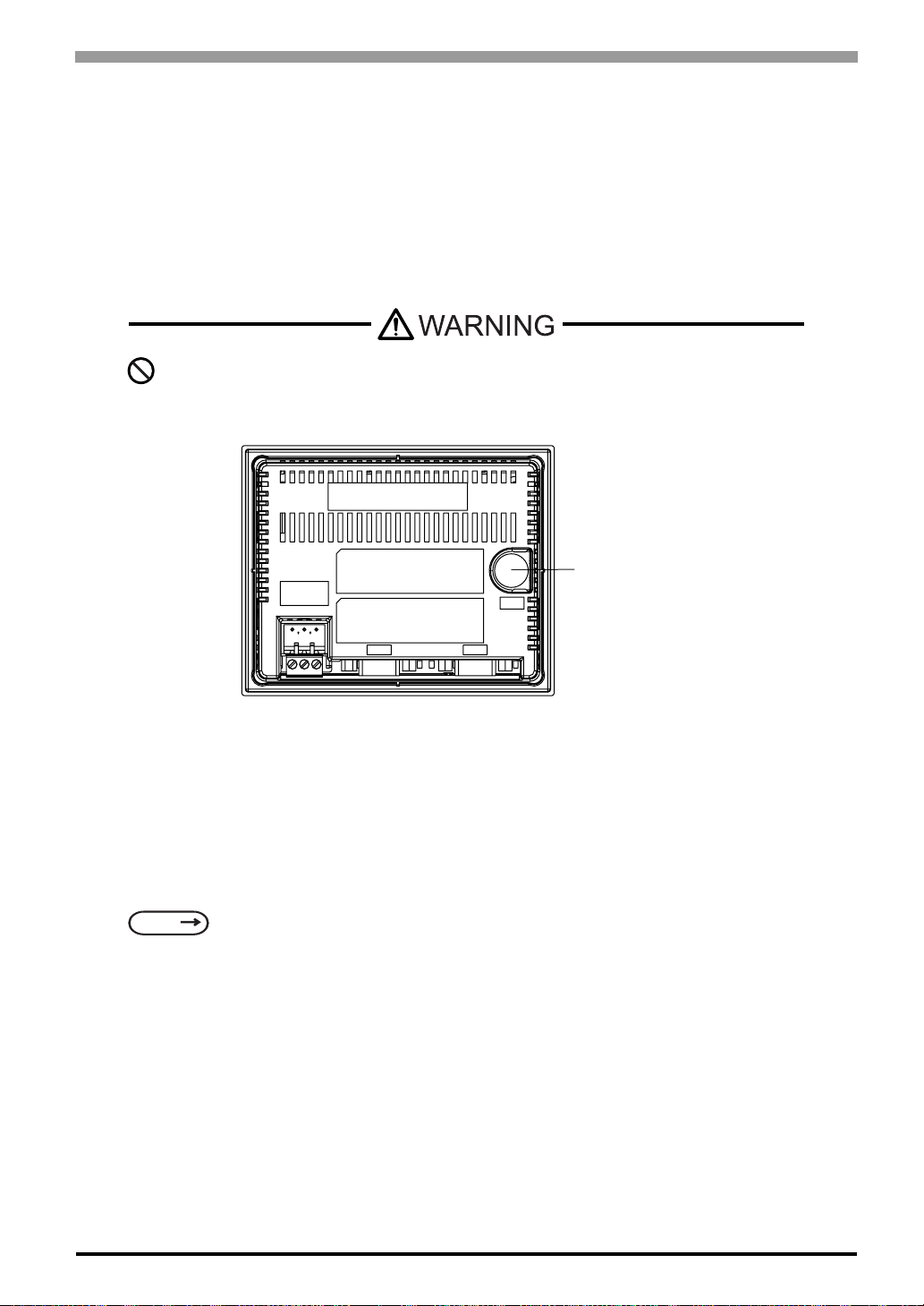
3.3 Tool Connector
The ST’s Data Transfer Cable, Memory Loader, or the Bar Code Reader can be attached to the ST
unit’s Tool Connector.
To prevent an electric shock, unplug the ST unit’s power cord from the main power supply
prior to attaching or detaching any connector(s) to or from the ST.
Rear
When the Bar Code Reader uses a separate power supply:
• Turn the Bar Code Reader ON before turning the ST ON.
• Turn the ST OFF before turning the Bar Code Reader OFF.
About Connectable Bar Code Reader,
SEE
Recommended Units (page 1-8)
Tool Connector
3-11
Page 53
ST Series User’s Manual
3.4 Ethernet Cable Connector
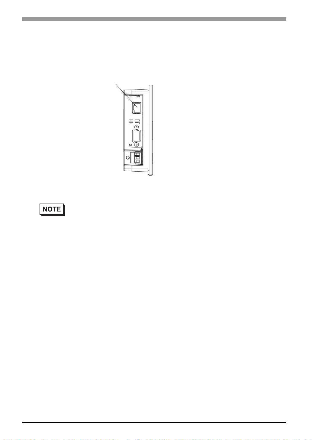
Use the following drawing to locate your ST unit’s Ethernet connector. The ST Ethernet interface is
IEEE802.3 compatible, and transmits data at 10Mbps. (The Ethernet I/F is equipped on only the ST.)
'VJGTPGV+PVGTHCEG$#5'6
56WPKV
$QVVQO
• It is strongly recommended that your Ethernet network is installed by a trained engineer.
• 1:1 connections using a cross cable may not be possible depending on the type of personal
computer and network card you are using. Make sure to use a hub for connection.
3-12
Page 54

4 Data Transfer
4.1 Serial Data Tr a n sfe r
4.2 Ethernet Data Transfer
4-1
Page 55
ST Series User’s Manual
4.1 Serial Data Transfer
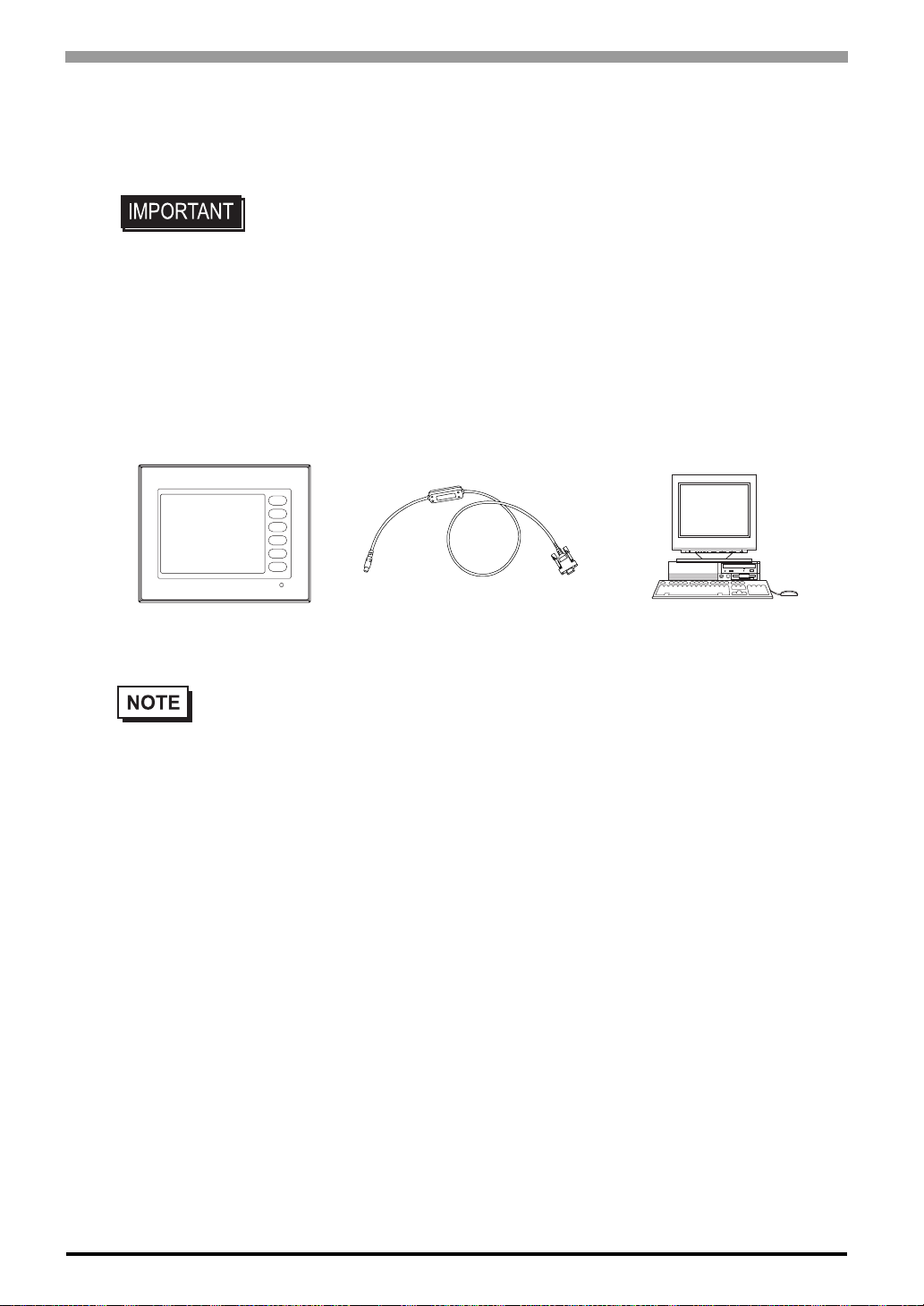
The following explains how to connect Pro-face’s data transfer cable to your PC and to the ST.
• Please connect it at an angle correct so as not to push it forcibly with the connector when you install the cable. The main body and the connector might break
down.
Connection of data transfer cable
When using data transfer cable (GPW-CB02)
The tool connector in the back of the main body is connected with the serial port of
the personal computer with the data transfer cable.
ST
PC
Connected to the
ST's Tool Connector
• Pro-face’s transfer cable (GPW-CB02) is sold separately. The transfer cable package does not
include the PC’s interface converting adapter.
• When using the PC with the Dsub 25pin socket side interface, a connector conversion adapter is
required. Use the straight line type conversion adapter.
Recommended units:
•Arvel AA833
•SANWA SUPPLY INC. D09-9F25F
• When using a PC equipped with a half-pitch 14pin socket interface, a conversion adapter is
required.
Recommended unit:
•LOAS Co. Ltd. ZR01-024
Connected to the
PC's serial port
4-2
Page 56
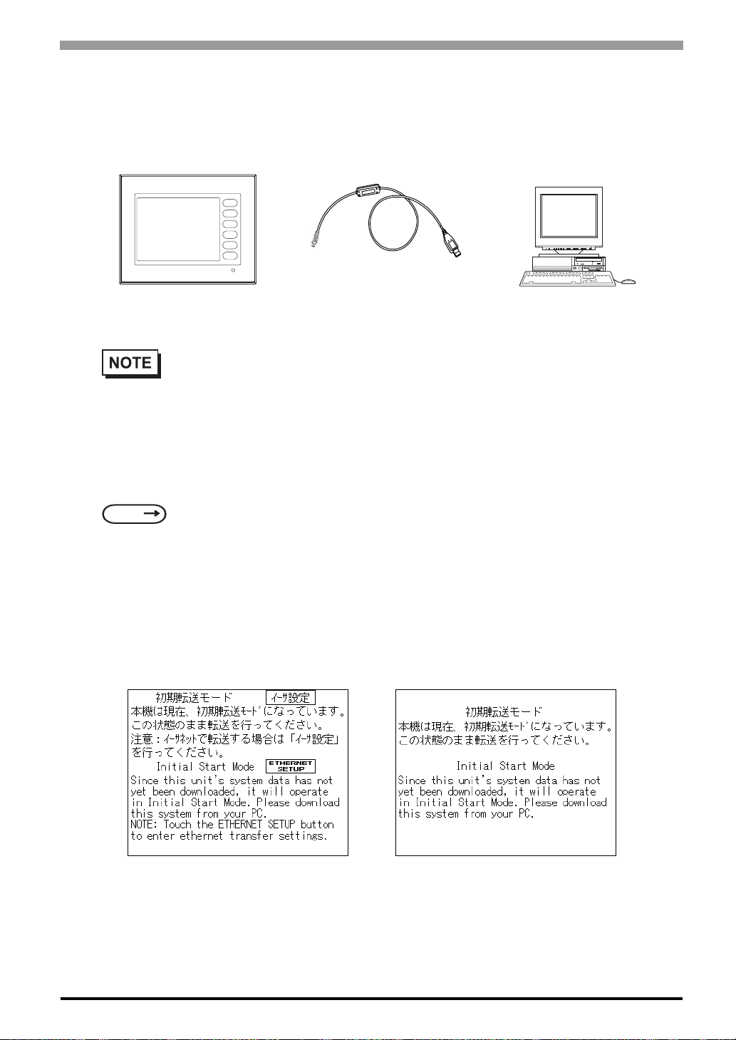
Chapter 4 Data Transfer
When using USB transfer cable (GPW-CB03)
Please install the USB connector of the USB transfer cable in the USB port of the personal computer.
ST
Connected to the
ST's Tool Connector
• USB transfer cable (GPW-CB03) is an optional. When USB transfer ca ble is used, it is necessary
to install the driver by setting up the cable bundle CD. Please see the manual of USB transfer
cable for details.
Transfer screen data from your PC, via the screen editor software.
For details about the screen editor software,
SEE
GP-PRO/PBIII for Windows Operation Manual (included in the screen editor software)
Connected to the
PC's USB port
PC
To Transfer Data to a Completely New ST
Connect the ST to your PC via the data transfer cable, and then turn the ST ON. The “Initial Start Mode”
screen will appear on the ST and you can transfer screen from your PC. The screen will change to the “Transfer” screen automatically.
ST403 ST400/ST401/ST402
4-3
Page 57

ST Series User’s Manual
After Completing Data Transfer using ST setup*1
Transfer screen data from the screen editor software, and select the “Transfer” mode.
Please switch from an off-line mode to "Transmi ssion of the screen data" mode by hand power when not
changing. For more information about OFFLINE MODE,
SEE
During data transfer, the “S ETUP Transfer” and “Now Transferring - Please Wait” messages will appear.
When these messages disappear, screen data transfer is completed.
If you wish to stop data transfer, simply cancel it from your PC’s screen editor software.
If you try to set up the ST after data transfer, the OFFLINE mode’s “Main Menu” will appear. If you do NOT
set up the ST, the screen designated in “INITIAL SETTINGS/SCREEN SETUP/INITIAL SCREEN FILE
NO.” will appear and the screen will change to operation (RUN) mode.
5 OFFLINE Mode (Page 5-1)
• Do NOT disconnect the ST’s power supply, turn OFF the PC, or disconnect the
ST’s transfer cable during the data transfer. If you do, an error may occur when
the ST is started.
4-4
• If the screen editor software’s “GP SYSTEM SETTINGS” data is transferred to the ST, the
OFFLINE mode “INITIAL SETTINGS” data will be overwritten.
*1 Here, the term “Set up” refers to the process of sending system program and protocol program informa-
tion to the ST via the screen editor software, so that the ST can be used as an operator interface.
Page 58
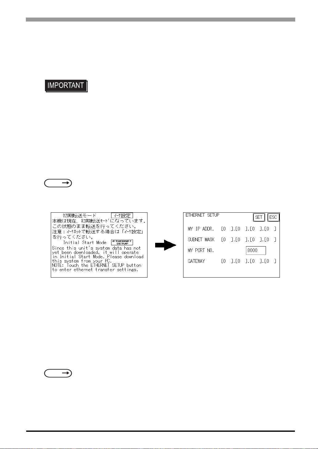
4.2 Ethernet Data Transfer
The ST403 unit is equipped with the Ethernet I/F which allows you to setup the ST via an Ethernet network,
as well as transfer ST screen data. (Unlike ST403 the other units are not equipped with the Ethernet I/F.)
• When using the Ethernet communication protocol, you must specify the port
number for the protocol as +10 or higher than the value specified in this section.
Otherwise, the setup or screen data transfer via Ethernet is disabled.
After you connect an Ethernet cable to the ST’s Ethernet I/F, the ST will appear on the Ethernet network.
Transferring Data to a Completely New ST
Setting Up the IP Address Manually and sending data to a ST Touch the “Ethernet Setup” button
on the ST403 Initial Start Mode screen.
Chapter 4 Data Transfer
SEE
Use this method if the ST has been previously set up and data transferred to it.
Using a previously set up IP Adrdress to send data
When the settings in the “Ethernet Setup” s creen are not specified and data is sent, the ST u nit’s factory-set IP
Address settings are used.
If you choose to use the factory-set IP address, be sure to designate the PC’s IP Address from “10.255.255.1”
to “10.255.255.254” and the subnet mask as “255.0.0.0”.
6.5.4 Ethernet Setup (page 6-24)
*1
Use the GP-PRO/PBIII for Windows software to transfer the data.
SEE
*1 Be sure to use 2-Way2000 version 3.10 or higher. This version data can be seen in the bottom left-hand
“GP-PRO/PBIII for Windows Operation Manual” (included in the screen editor software package)
corner of the [Initial Start Mode] screen.
4-5
Page 59
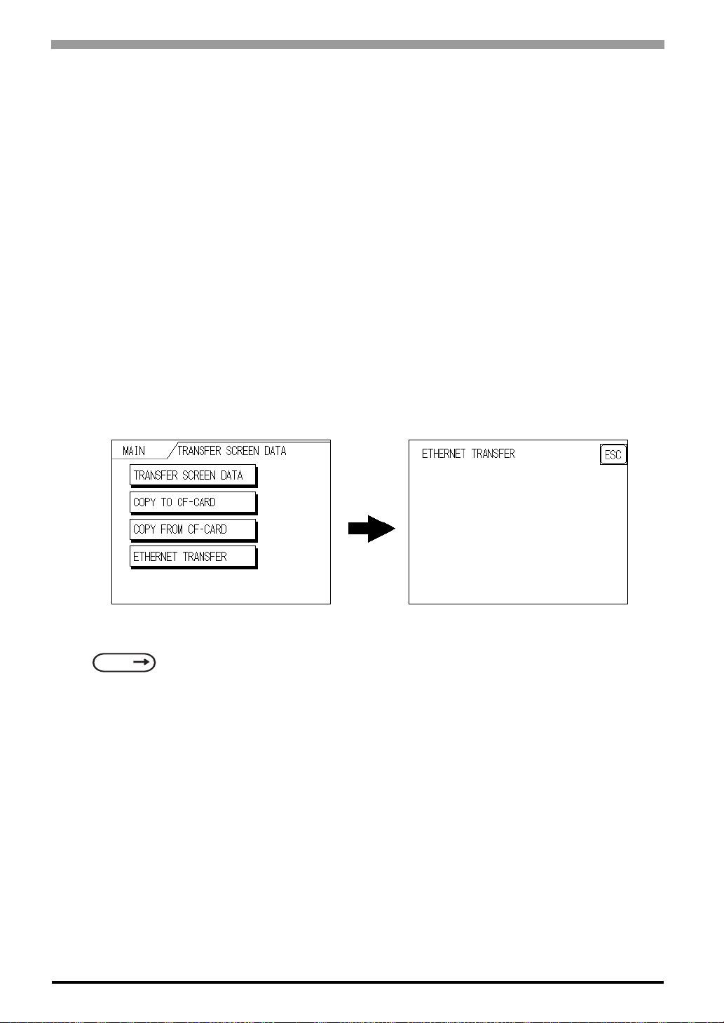
ST Series User’s Manual
When transferring data using the ST setup*1 is completed
How to manually set an IP address and transfer data
Set an IP address in the OFFLINE mode “INITIAL SETTING / OPERATING ENVIRONMENT SETTING /
EXTENSION SETTING / ETHERNET INFORMATION SETTING”. However, in case that an IP address is
preset in the PC’s screen editor software, the IP address is set in the ST. If the transferred IP address is used,
setting the ST’s IP address again in the OFFLINE mode is not needed.
Set an IP address in the ST's through “INITIAL SETTING / OPERATING ENVIRONMENT SETTING /
EXTENSION SETTING / ETHERNET INFORMATION SETTING” menu.
When you transfer screen data from your PC to the ST while the ST is in RUN mode, the screen will change
automatically to “Ethernet Mode”. If it does not, you will need to manually change the ST screen to Ethernet
Mode, via the following screen.
4-6
You can now transfer data from your PC’s screen editor software.
SEE
How to transfer data using a previously-set IP address
When transferring data without first setting up an IP address in the screen editor software, your ST unit's factory-set IP address is used.
When transferring data using your ST unit's factory-set IP address, be sure to set “10.255.255.1” to
“10.255.255.254” as your PC’s IP address, and “255.0.0.0” for your PC's subnet mask.
The data transfer method is the same as when the IP address was manually set.
*1 Here, the term “Set up” refers to the process of sending ST screen, system program and protocol pro-
*2 Be sure to use 2-Way2000 version 3.10 or higher. This version data can be seen in the bottom left-hand
“GP-PRO/PBIII for Windows Operation Manual”
*2
gram information to the ST via the screen editor software, so that the ST can be used as an operator
interface.
corner of the [Initial Start Mode] screen.
Page 60
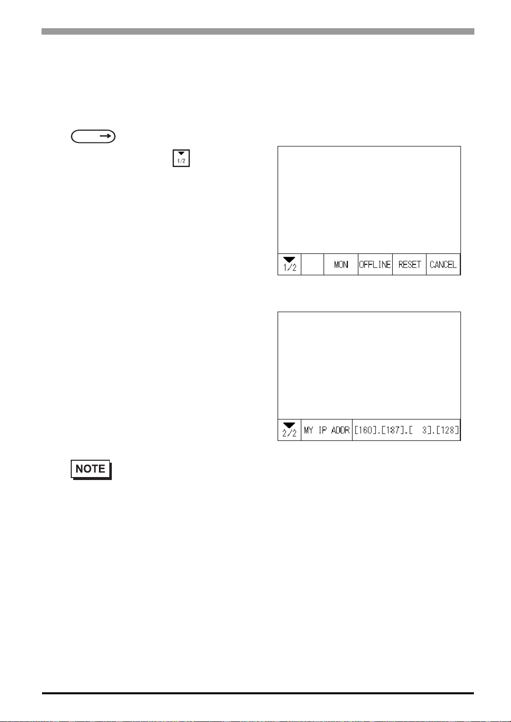
Chapter 4 Data Transfer
Checking the IP Address
Use the following procedure to check the IP Address assigned to the ST and some consideration/precautions.
1) Display the menu bar. For instructions on how to display the menu bar,
SEE
2) Click on the left-side cell of the menu bar
to display the next menu.
3) The IP Address assigned to the ST will appear
in the menu bar.
6.4.3 Set Up Touch Panel (page 6-13)
• The IP Address will not be reflected unless ST was reset or power cord was reconnected. After
changing “Ethernet Setup” settings, the ST must then be reset or power cord must be reconnected.
4-7
Page 61
ST Series User’s Manual
Memo
4-8
Page 62

5 OFFLINE Mode
5.1 Entering OFFLINE Mode
5.2 OFFLINE Mode Main Menu
5.3 Initialization
5.4 Self-Diagnosis
5-1
Page 63
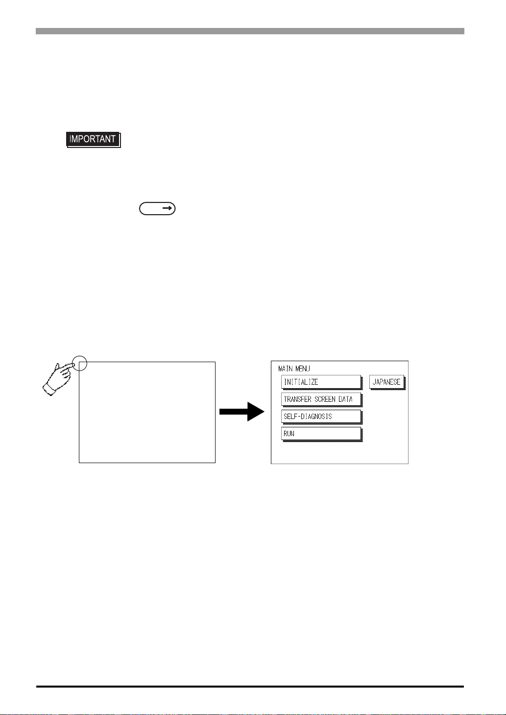
ST Series User’s Manual
5.1 Entering OFFLINE Mode
To initialize your ST or perform self-diagnosis, you must first switch the ST to OFFLINE mode. There are
two ways to enter OFFLINE mode. First, is immediately after plugging in the ST's power cord, and second, by
using the Forced Reset feature.
• If the system is not forwarded from the screen editor software to ST when ST is
used for the first time after it buys it, it does not put it in an offline mode (initialization).
For more information about DATA TRANSFER
SEE
Connection with the screen editor software).
It is necessary to shift to an offline mode for initialization with ST, and the self-diagnosis, etc. It is possible to
enter an offline mode by the following two methods.
4 Data Transfer (Page 4-1) or GP-PRO/PBIII for Windows Device/PLC
5.1.1 After Plugging in the Power Cord
Touch the upper left-hand corner of the ST screen within 10 seconds of plugging in the ST's power cord and
the ST will change to OFFLINE mode.
5-2
Page 64
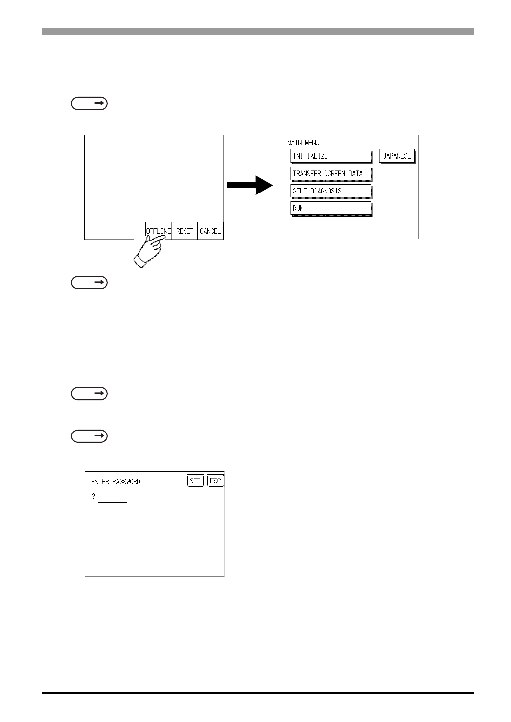
5.1.2 From the Menu Bar
From the ST unitís Menu Bar, touch the OFFLINE square an d the OFFLINE mode Main Menu will appear
Chapter 5 OFFLINE Mode
SEE
SEE
If a Password has been entered in the Initialize/ Set Up System area, before entering the OFFLINE mode, the
following screen appears.
Here, enter the password, then touch Set to enter OFFLINE mode.
When Passwords setting
6.4.3 Set Up Touch Panel SYSTEM RESET MODE (Page 6-14)
GP-PRO/PBIII for Windows Device/PLC Connection Manual (included with the screen editor software)
SEE
For more information about ENTERING NUMBER
SEE
6.3.1 System Setup PASSWORD SETUP (Page 6-5)
5.3 Initialization Entering Numbers (Page 5-5)
5-3
Page 65
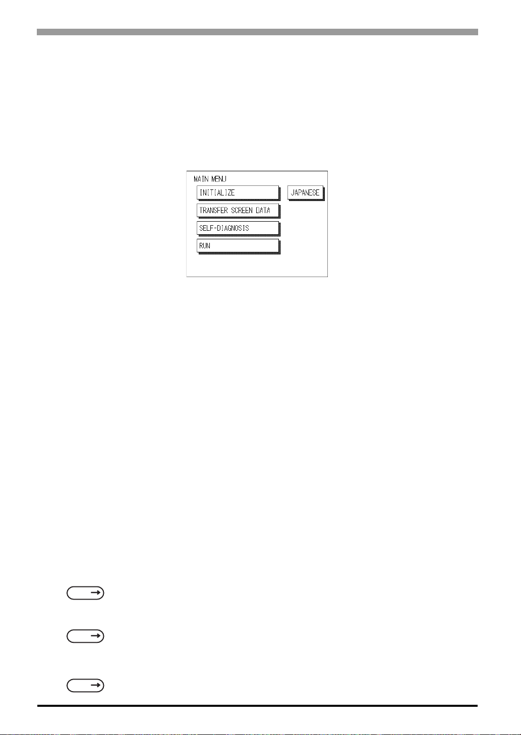
ST Series User’s Manual
5.2 OFFLINE Mode Main Menu
Each menu item shown below has different settings that must be set to match the corresponding PLC in order
for the ST to communicate properly.
Entering OFFLINE mode calls up the following screen.
Select the desired menu item by touching the corresponding screen item bar.
Each Main Menu item is used as follows.
INITIALIZE
The setup items contained in this menu are used to control the ST unit.
SCREEN DATA TRANSFER
Select to transfer screen data to and from the screen editor software.
SELF-DIAGNOSIS
Checks to see if there are any problems with the ST System or Interface (I/F).
RUN
Starts ST operation.
LANGUAGE CHANGEOVER FUNCTION
When in Japanese display mode, touch the [ENGLISH] button to change to the English display. Similarly, in
English display mode, touch the [JAPANESE] button to change to the Japanese display. Default display mode
is English.
For more information about INITIALIZE
SEE
For more information about TRANSFER SCREEN DATA
6 Initializing the ST (Page 6-1)
5-4
SEE
For more information about SELF-DIAGNOSIS and RUN
SEE
4 Data Transfer (Page 4-1) or GP-PRO/PBIII for Windows Operation Manual (included with the
screen editor software)
7 RUN Mode and Errors (Page 7-1)
Page 66
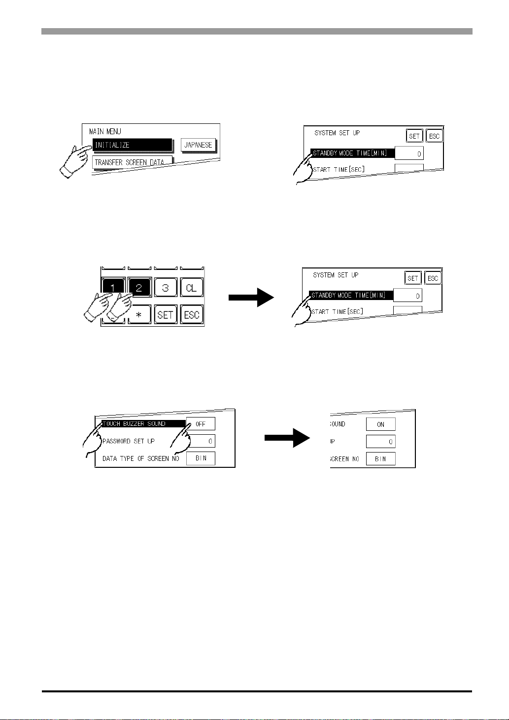
5.3 Initialization
Selecting A Menu
Touch the menu item, or input field to select it.
Entering Numbers
After selecting an input field by touching it, use the numeric touch keys located at the bottom of the screen to
enter numeric values. After inputting each value, touch the [SET] key to define the value.
Chapter 5 OFFLINE Mode
Selecting Setup Conditions
After selecting a menu item and entering that area, touch the option you would like to setup. The selected
item becomes highlighted. In this example, the TOUCH BUZZER SO UND has b ee n set Off.
5-5
Page 67
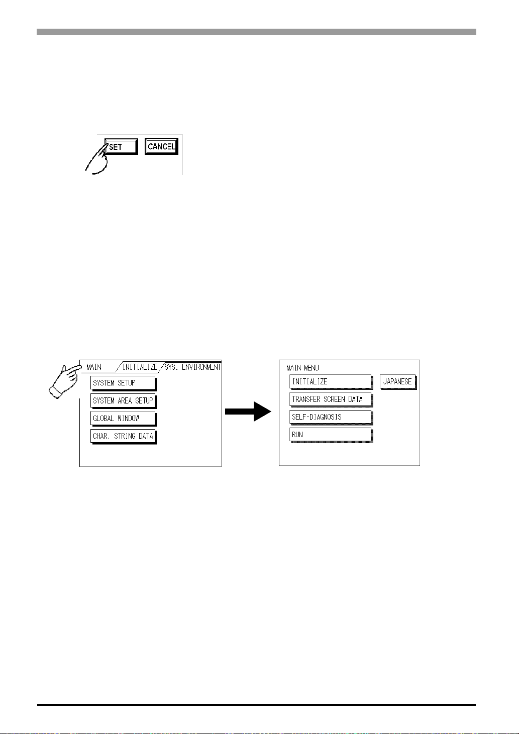
ST Series User’s Manual
After All Setting Data is Entered
Touch the top-right [SET] button.
If you wish to exit the screen without saving the changes, touch the CANCEL button.
Return To Previous Screen
Tou ch the title of the screen you would like to return to.
• Press the [SET] key to write the Setup conditions onto the Internal
FEPROM, which may take some time, causing a delay in returning to the previous screen. Therefore, do not touch the screen
until the previous menu display returns.
• Press the [SET] key to write the Setup conditions onto the Internal
FEPROM, and Press the [CANCEL] key to not write the Setup
conditions onto the Internal FEPROM and return to the previous
menu.
E.g. To return to the MAIN MENU from the SYS.ENVIRONMENT screen, simply touch the MAIN MENU
title.
5-6
Page 68
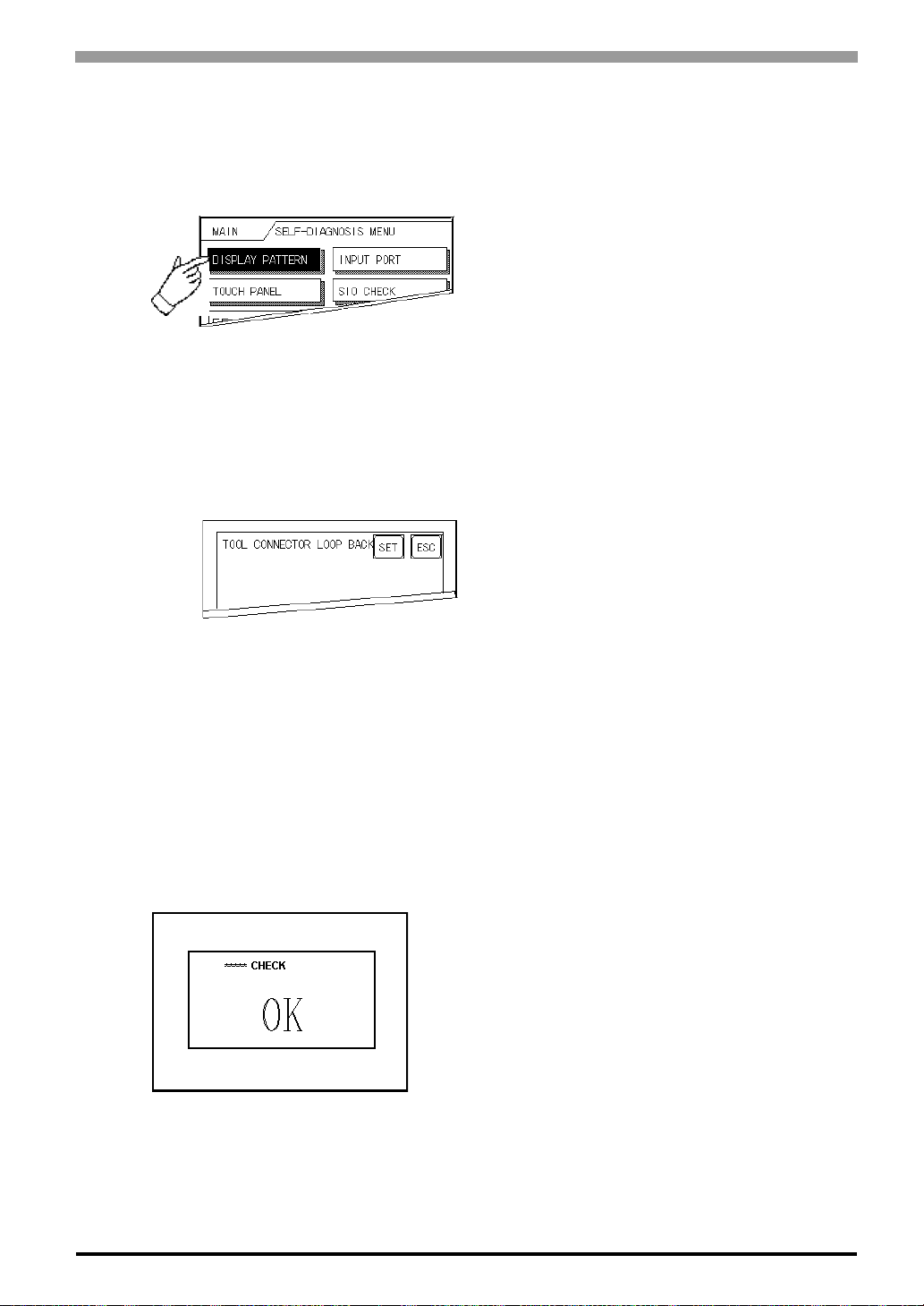
5.4 Self-Diagnosis
Selecting a Sub-Display
Touch the desired the menu item and that sub-display will appear.
[SET], [ESC] Keys
After selecting the Self Diagnosis item, the [SET], and [ESC] keys may appear at different times at the top of
the screen.
Chapter 5 OFFLINE Mode
[SET] Key
When this key is pressed, your selected Self-Diagnosis test begins.
[ESC] Key
When this key is pressed, the selected Self-Diagnosis test is cancelled, and you are returned to the SELFDIAGNOSIS menu.
After Check To Return To Self-Diagnosis Menu
When OK displays,
Pressing once anywhere on the display screen returns you to the Self-Diagnosis menu.
5-7
Page 69
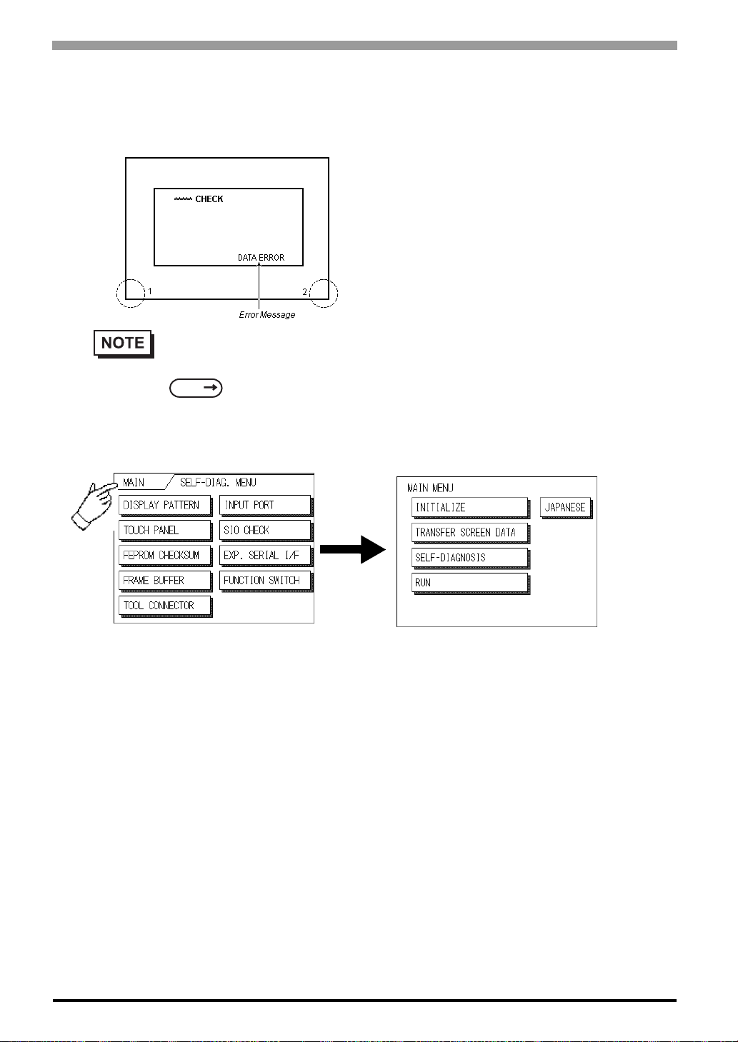
ST Series User’s Manual
When an Error Message displays
To return to the self-diagnosis menu screen when the error message is displayed by the self-diagnosis, it
pushes in order in the lower left corner of the displayed screen (1) and the lower right corner (2).
When the lower left corner is pushed while pushing the lower right corner of the screen (2), the brilliance control is displayed.
SEE
6.4.3 Set Up Touch Panel
BRIGHTNESS ADJUSTMENT (Page 6-15)
Return To Main Menu
Touch the MAIN Key in the top right corner of the SELF-DIAGNOSIS menu to return to the MAIN MENU.
5-8
Page 70

6 Initializing the ST
6.1 Initialization Screen
6.2 Initialization Items
6.3 System Environment Setup
6.4 Set Up I/O
6.5 PLC Setup
6.6 Initialize Internal Memory
6.7 Set Up Time
6.8 Set Up Screen
6.9 Font Setting
6-1
Page 71
ST Series User’s Manual
6.1 Initialization Screen
Occasionally, you may want to change your ST's general operation settings. The settings used for this are
found in the INITIALIZE option in the ST OFFLINE mode's MAIN MENU.
*1 This chapter explains each of the OFFLINE mode's INITIALIZE items. However, there are 2 types of
INITIALIZE settings, those for the 1:1 connection and those for the n:1 (multi-link) connection
The n:1 mark appears on original menu items related to n:1 multi-link connection items. If there is no mark,
the menu item is common to both 1:1 and n:1 connections.
1:1 A single (1) ST is connected with a single (1) PLC.
n:1 Multiple STs are connected with a single PLC. The STs successively pass a PLC Access Token (exclu-
sive PLC interaction key) among themselves to designate which unit can communicate with the PLC.
• If you transfer the ST's system file data to the ST via your screen editor software*2, the ST operates using that data. If the ST System file has been correctly setup and transferred, the setting of
INITIALIZE items become unnecessary.
*1
.
For more information about ST System files,
SEE
"GP-PRO/PB III for Windows Operation Manual" (included with the screen editor
software)
6-2
*1 PLC's that support the n:1 (multi-link) connection are limited.
SEE
editor software)
*2 Refer to the screen editor software's "SYSTEM SETTINGS" area.
GP-PRO/PB III for Windows Device/PLC Connection Manual" (included with the scre en
Page 72
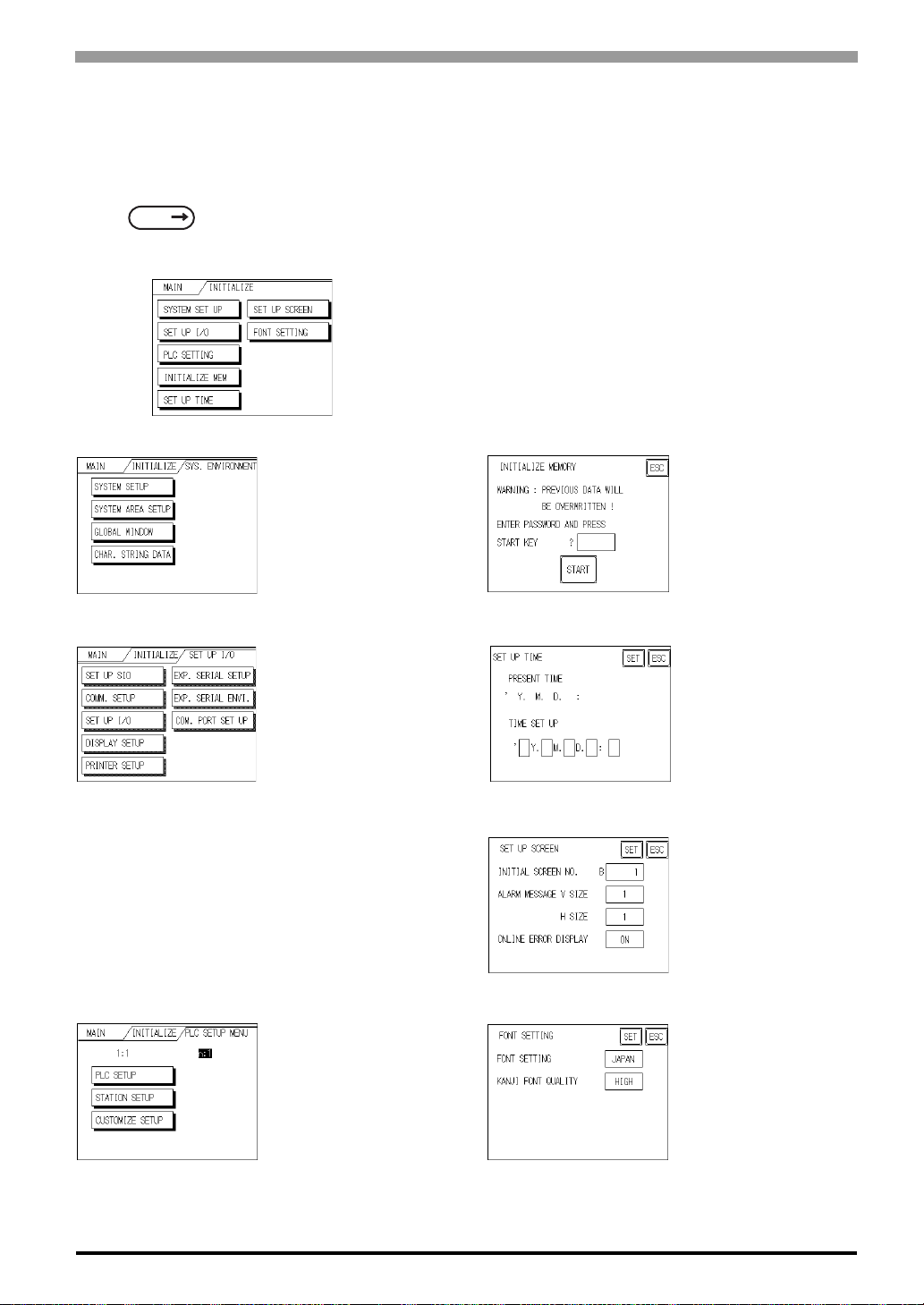
6.2 Initialization Items
This chapter explains the contents of the Initialize setup items listed below. For information about screen
operations and numeric input.
Chapter 6 Initializing the ST
SEE
The INITIALIZE menu includes the following items.
5 OFFLINE Mode (Page 5-1)
SYSTEM ENVIRONMENT
SETUP
SYSTEM SETUP
System Area SETUP
Global Window
CHAR. STRING DATA
SET UP I/O
SET UP SIO
COMM. SETUP
Set Up I/O
DISPLAY SETUP
PRINTER SETUP
EXP. SERIAL SETUP
EXP. SERIAL ENVI.
COM. PORT SET UP
INITIALIZE MEMORY
INITIALIZE MEMORY
SETUP TIME
SETUP SCREEN
PLC SETUP MENU
1:1/n:1
PLC SETUP
STATION SETUP
CUSTOMIZE SETUP
*1 Note that, depending on the Device/PLC type selected, the screens that appear in your screen editor soft-
ware will vary.
*1
FONT SETTING
6-3
Page 73
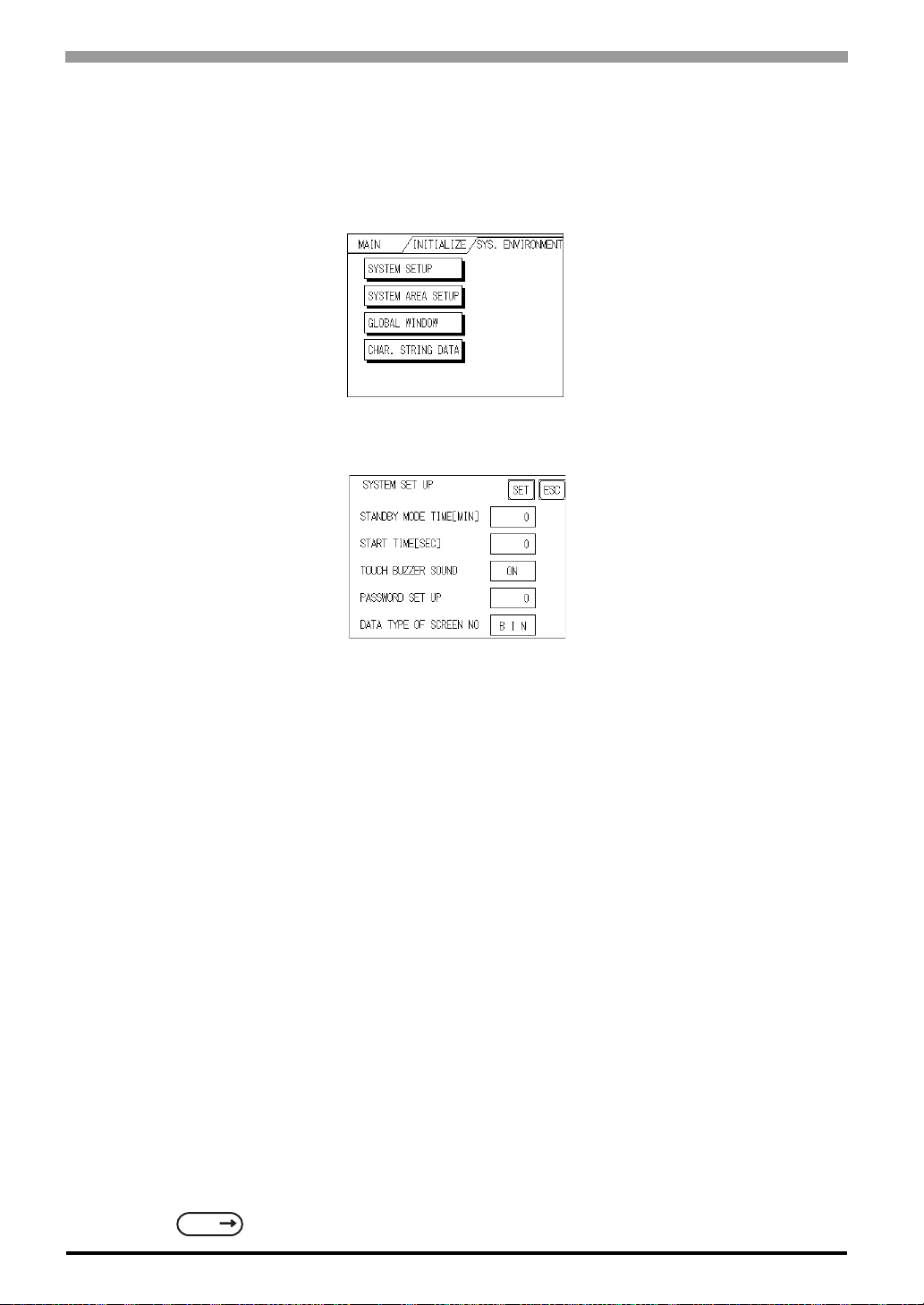
ST Series User’s Manual
)
6.3 System Environment Setup
These settings allow you to adjust the ST's operation environment. System Environment SETUP includes
the SYSTEM SETUP, SYSTEM DATA AREA, GLOBAL WINDOW SETUP, and CHARACTER STRING
DATA SETUP screens.
6.3.1 System Setup
STAND-BY MODE TIME [MIN]
To extend the life of the ST's backlight, the ST is equipped with a screen saver function that automatically
turns the unit's backlight (s) OFF when no operations have occurred for a designated period of time. A "0"
entered in this field causes a normal display, i.e. the screen is cleared after the ST's standard default time
elapses.
*1
When SYSTEM DATA AREA's SCREEN DISPLAY OFF
not performed on the screen for the User's designated period of time, the ST's current display is turned OFF.
(Reference : "GP-PRO/PBIII for Windows Device/PLC Connection Manual" - included with the screen editor software)
•Change Screen
•Touch Screen
•Alarm Messages (scrolling display)
•Error Message Display
•Menu Bar (for forced reset) display
*1 When using the Direct Access or the Memory Link formats, the object address becomes +9 or +12,
respectively. (Only when all items are set within the System Data Area.)
SEE
"GP-PRO/PBIII for Windows Device/PLC Connection Manual" (included with the screen
creation software
data is 0000h, and the following operations are
6-4
Page 74
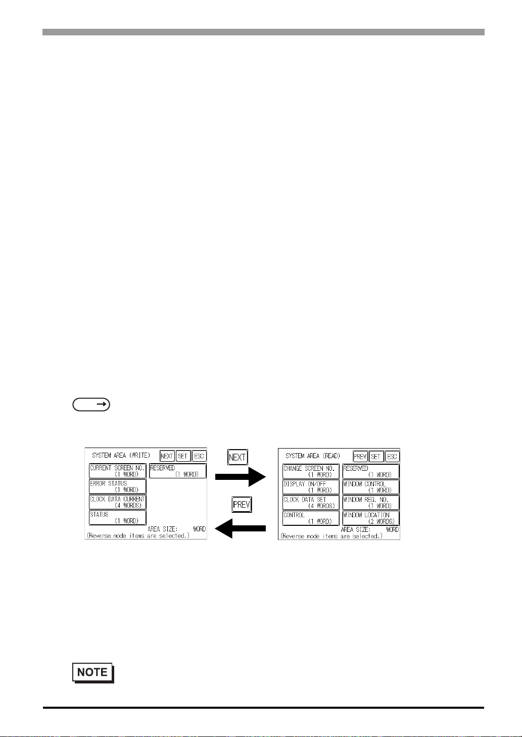
Chapter 6 Initializing the ST
START TIME [SEC]
This setup determines the start-up time of the ST. Use this setup to adjust the power up sequence so that the
ST starts up after the PLC.
TOUCH BUZZER SOUND
Setup whether or not the ST beeps when pressed.
PASSWORD SETUP
The password setting is used when changing to the Initialize Memory or Initialize (OFFLINE mode) Screens.
The password (from 0 to 9999) ensures protection of the ST settings, since the use of OFFLINE mode is controlled. If you do not wish to use this feature, enter the default value, 0.
DATA TYPE OF SCREEN NO.
This setup controls whether BIN or BCD format numbers are used when making screen changes. Screen numbers 1 to 8999 are available for binary format; screen numbers 1 to 1999 are available for BCD format.
6.3.2 System Area Setup
SYSTEM AREA SETUP is necessary for the PLC to control its ST-related data, and prepares the PLC internal Data Memory (DM) and Data Register (D)*1. Use this setup to prepare the desired SYSTEM DATA
AREA items. SYSTEM DATA AREA is located in the LS area of the ST's internal area.
SEE
When using the Memory Link format, this setting is unnecessary.
Press the item, and when the item is highlighted, it has been selected.
When you press the Confirm key, the System Area Contents screen appears to confirm the selected items.
System Area Size
GP-PRO/PB III for Windows Device/PLC Connection Manual (included with the screen editor
software)
This field displays the total number of words used for the items selected from the SYSTEM AREA SETUP
(Write and Read ).
• The setup shown is enabled only when using the Direct Access format.
• The selected System Area items, as displayed on the screen , bec o me the System Data Area.
6-5
Page 75
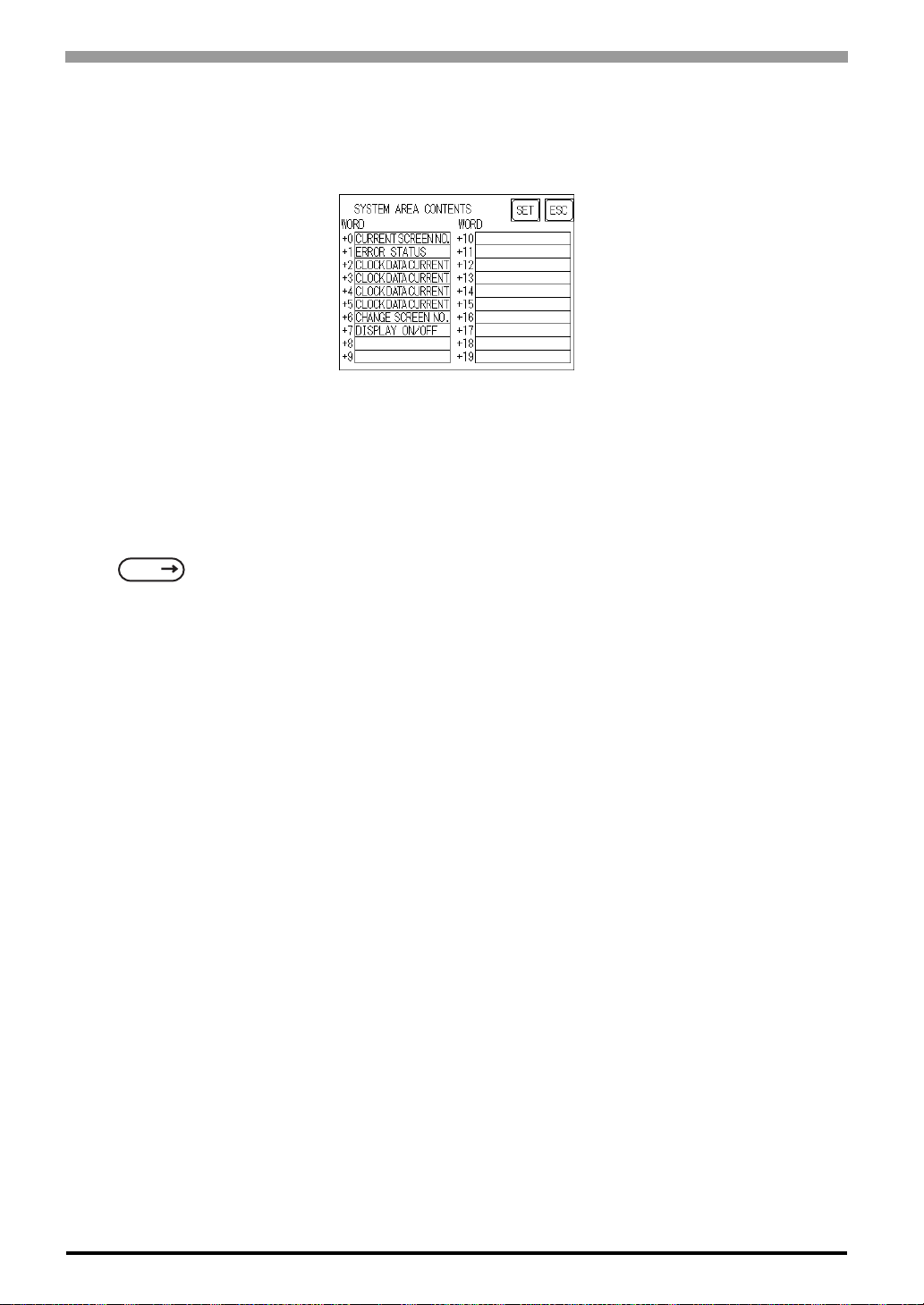
ST Series User’s Manual
When these five items, "Current Screen Number", "Error Status", "Clock Data (Current)", "Change Screen
Number", and "Display ON/Off", have been selected, word addresses are assigned to each item, in order, as
shown here.
The System DataArea selection process follows this formula [System Data Start Address + n]. For example,
if the System Area Start Address was D00200, and the Change Screen Number option had been selected if
you refer to the System Area Contents screen displayed above because Change Screen No's address is +6, its
word address would be D00200+6=D00206.
For information about how to use the System Start Address and Start Address
SEE
6.5.1 SET UP OPERATION SURROUNDINGS (1:1/n:1) (Page 6-19)
6-6
Page 76
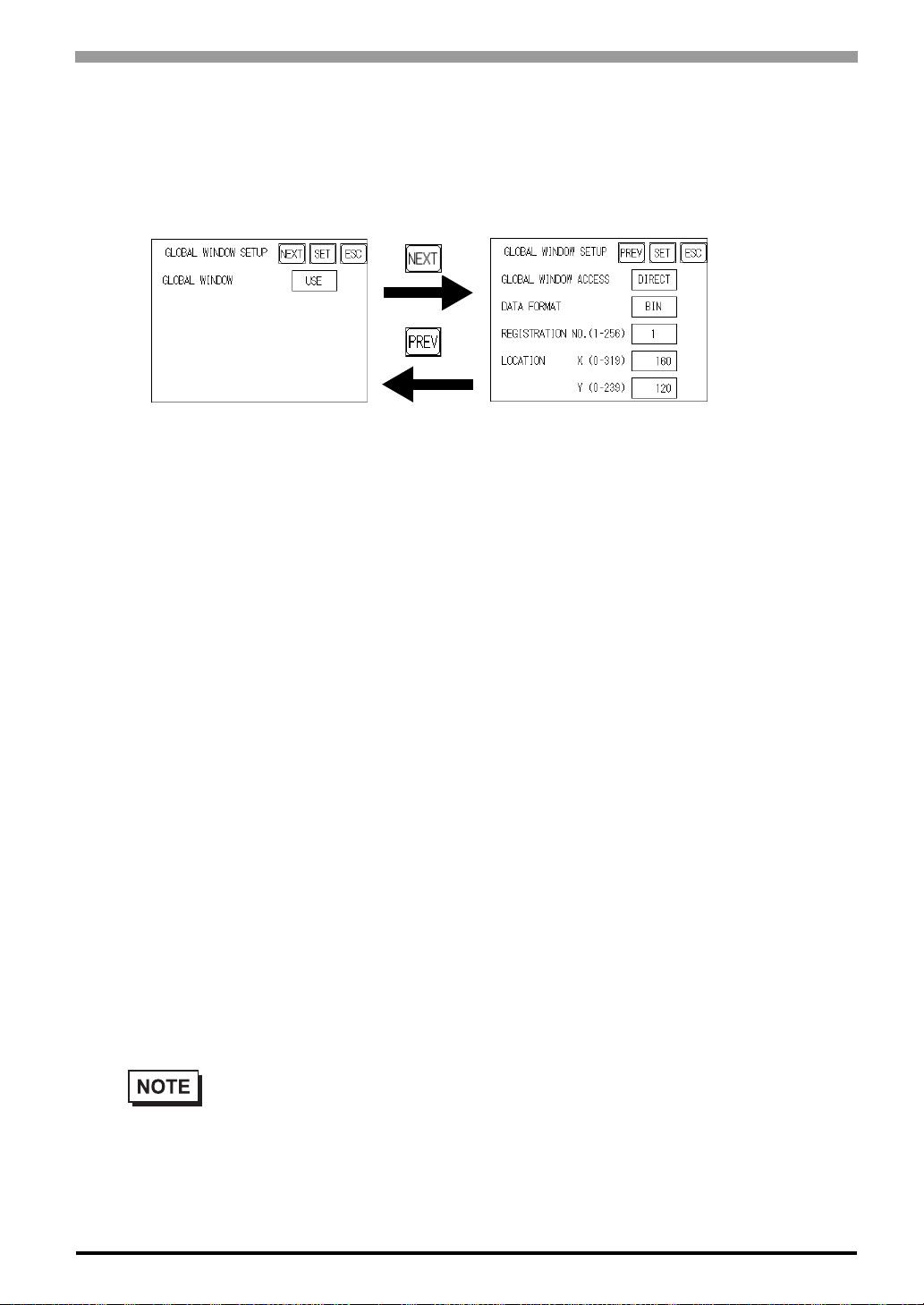
6.3.3 Global Window Setup
The ST unit can display three screens at any one time, one Global Window and two Local
Windows. The Global Window is common to all the display screens. The Local Window displays exclusively
on the corresponding base screen. The GLOBAL WINDOW SETUP is described here.
GLOBAL WINDOW
There are two options here: Use and Do Not Use. If you select Do Not Use, ignore the items described below .
Selecting Use enables these options.
Chapter 6 Initializing the ST
GLOBAL WINDOW ACCESS
Use this feature to designate whether a value used is DIRECT or INDIRECT, i.e. the REGISTRATION NO.
and the LOCATION values.
When set as Direct, the REGISTRATION NO. and LOCATION selections are fixed to the values entered
here. When set to Indirect, the WINDOW REG. NO.'s word address, as prepared in the System Area, is a
variable. This means it can have the REGISTRATION NO. written to it and, as a result, multiple window
screens can be used as Global windows. You can use this method to adjust the Global window position by
writing the X,Y coordinates to the SYSTEM AREA's LOCATION word addresses.
DATA FORMAT
Setup whether the REGISTRATION NO. and the LOCATION values are BIN or BCD values. This field is
related only to indirect values.
REGISTRATION NO. (1-256)
Enter the Window Screen Number used by the Global Window. This field is enabled only when GLOBAL
WINDOW ACCESS is set to direct.
• The screen editor software allows you to set a window number from 1 to 2000. If you wish to
use a number that is 257 or higher, be sure to use the screen editor software to enter this value.
6-7
Page 77
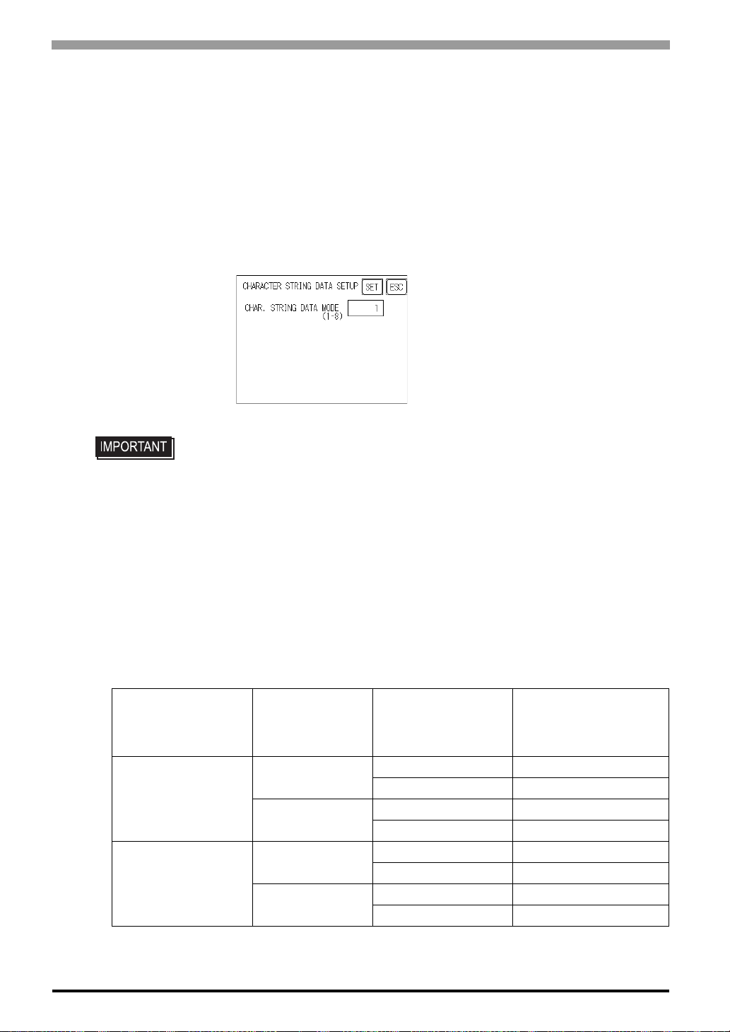
ST Series User’s Manual
LOCATION
Enter the value used for the (Global WINDOW) LOCATION. This field is enabled only when GLOBAL
WINDOW ACCESS is set to direct.
6.3.4 Character String Data Setup
Character String Data ordering varies from manufacturer to manufacturer. Setup the Character String Data
order here to match the corresponding PLC.
• Setup the Character String Data mode to match the PLC type. Device type and
Tag settings are unavailable.
CHARACTER STRING DATA MODE (1-8)
Find the data storage order for your PLC in the table, down below, and setup the CHARACTER STRING
DATA MODE.
(I) Data Device Storage Order
(II) Internal Word Byte LH/HL Storage Order
(III) Internal Double-word Word LH/HL Storage Order
Character String Data Mode List
(I)
Data Device
Storage Order
Storage from
Initial data
Storage from
End data
(II)
Internal Word,
Byte LH/HL
Storage Order
LH order
HL order
LH order
HL order
(III)
Double-word Internal
Word LH/HL Storage
Order
LH order 4
HL order 2
LH order 5
HL order 1
LH order 6
HL order 7
LH order 8
HL order 3
Character String
Data Mode
6-8
Page 78
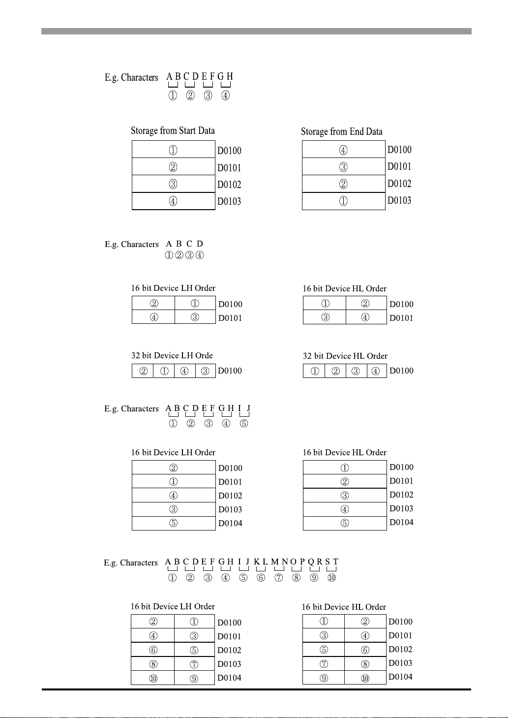
I) Data Device Storage Order
Chapter 6 Initializing the ST
E.g. Characters
ABCDEFGH
Storage from Start Data
II) Word Byte LH/HL Order
E.g. Characters
16 bit Device LH Order
32 bit Device LH Orde
ABCD
D0100
D0101
D0102
D0103
D0100
D0101
D0100
Storage from End Data
D0100
D0101
D0102
D0103
16 bit Device HL Order
D0100
D0101
32 bit Device HL Order
D0100
III) Double-word Word LH/HL Order
E.g. Characters
16 bit Device LH Order
E.g. Characters
16 bit Device LH Order
ABCDEFGHI J
ABCDEFGHIJKLMNOPQRST
D0100
D0101
D0102
D0103
D0104
D0100
D0101
D0102
D0103
D0104
16 bit Device HL Order
D0100
D0101
D0102
D0103
D0104
16 bit Device HL Order
D0100
D0101
D0102
D0103
D0104
6-9
Page 79
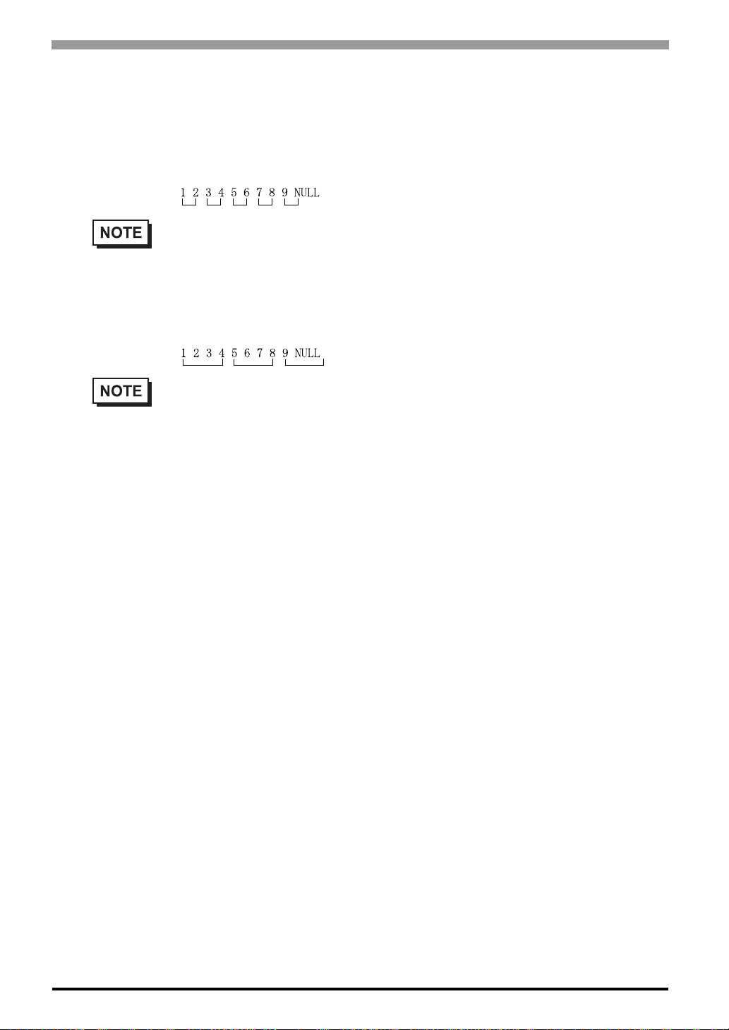
ST Series User’s Manual
Relationship between K-tag Write Character Value and PLC Device
16 bit Devices
ST stores the character string from the start, as groups of 2, into1 PLC Device.
When there are nine characters, they are arranged as shown below.
• When the characters do not divide into 2 evenly, NULL is added at the end.
32 bit Devices
ST stores the character string from the start, as groups of 4, into1 PLC Device.
When there are nine characters, they are arranged as shown below.
• When the characters do not divide into 4 evenly, NULL is added at the end.
6-10
Page 80
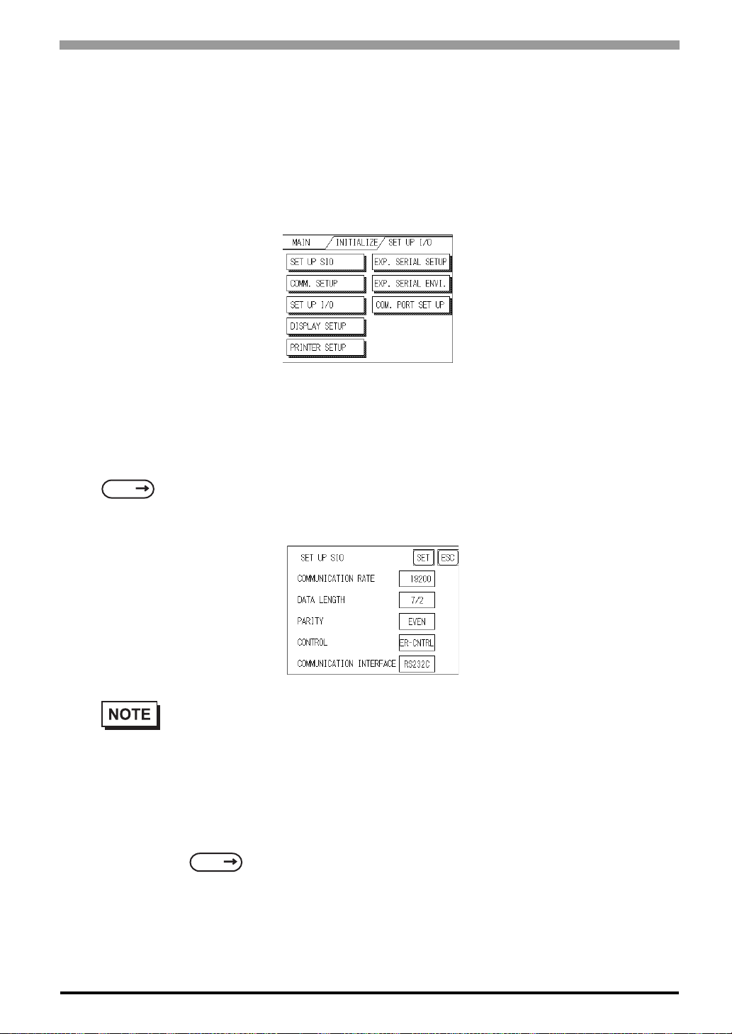
6.4 Set Up I/O
This section describes the communication setup with the Host (PLC) and the setup for any peripheral equipment. The SET UP I/O menu includes the SET UP SIO, COMMUNICATION SETUP, SETUP I/O, DISPLAY SETUP, PRINTER SETUP, EXPANSION SERIAL SETUP, EXPANSION SERIAL
ENVIRONMENT SETUP, SET UP CAPTURE OPERATION, FUNCTION SETUP and COMMUNICATION PORT SET UP menus.
6.4.1 SET UP SIO
This menu runs the settings related to PLC communication. Be sure to match the settings listed below with
Chapter 6 Initializing the ST
the SIO setup on the PLC host, if not, an error may occur.
SEE
GP-PRO/PBIII for Windows Device/PLC Connection Manual (included with the screen editor software) GP-PRO/PBIII for Windows
• If you have selected "YES" for the [SERIAL I/F CHANGE] on the [COMMUNICATION
PORT SETUP] screen, or "Yes" for the [Serial I/F Switch] settings in the [Change Extend SIO
Type] command, in the Screen Editor's [Project] menu, do not enter all of the settings related to
device communication using the Extended SIO Script Protocol here. ([SET UP SIO] screen)
These settings are required to set using the [EXPANSION SERIAL COMMUNICATION
SETUP] screen.
SEE
6.4.6 Expansion Serial Setup (Page 6-17)
6-11
Page 81
ST Series User’s Manual
COMMUNICATION RATE
The COMMUNICATION RATE (baud rate) is the data communication speed, measured in bits per second
(bps), between the ST and PLC. Match the COMMUNICATION RATE values in both the PLC and ST.
Depending on the rate selected, certain PLCs may not be able to be used.
SEE
GP-PRO/PBIII for Windows Device/PLC Connection Manual (included with the screen editor software)
DATA LENGTH
For data communications, the DATA LENGTH must be set up as 7-bit or 8-bit data, and set up also the STOP
BIT as either a 1-bit or 2-bit value.
PARITY
Set up whether no parity check, or an odd or even number parity check will take place during communication.
CONTROL
Data flow CONTROL prevents the overflow of data sent back and forth. Select either X-CNTRL or ERCONTRL.
COMMUNICATION INTERFACE
These settings are used for data communication.
When using the ST400 unit, select either RS-422 (2-wire) or RS-422 (4-wire).
When using the ST401 unit, the data communication method is fixed at RS-232C. This setting cannot be
6-12
changed.
When using the ST402 unit, the PLC's protocol setting screen is displayed.
When using the ST403 unit, select one from RS-232C, RS-422 (2-wire) and RS-422 (4-wire).
• When using an RS422 cable and the Memory Link format, be sure to select the 4-line option.
SEE
• If you have selected "Yes" for the [Serial I/F Switch] settings in the [Change Extend SIO Type]
command, in the Screen Editor's [Project] menu, be sure to select RS-232C.
GP-PRO/PBIII for Windows Device/PLC Connection Manual (included
with the screen editor sof tware)
Page 82
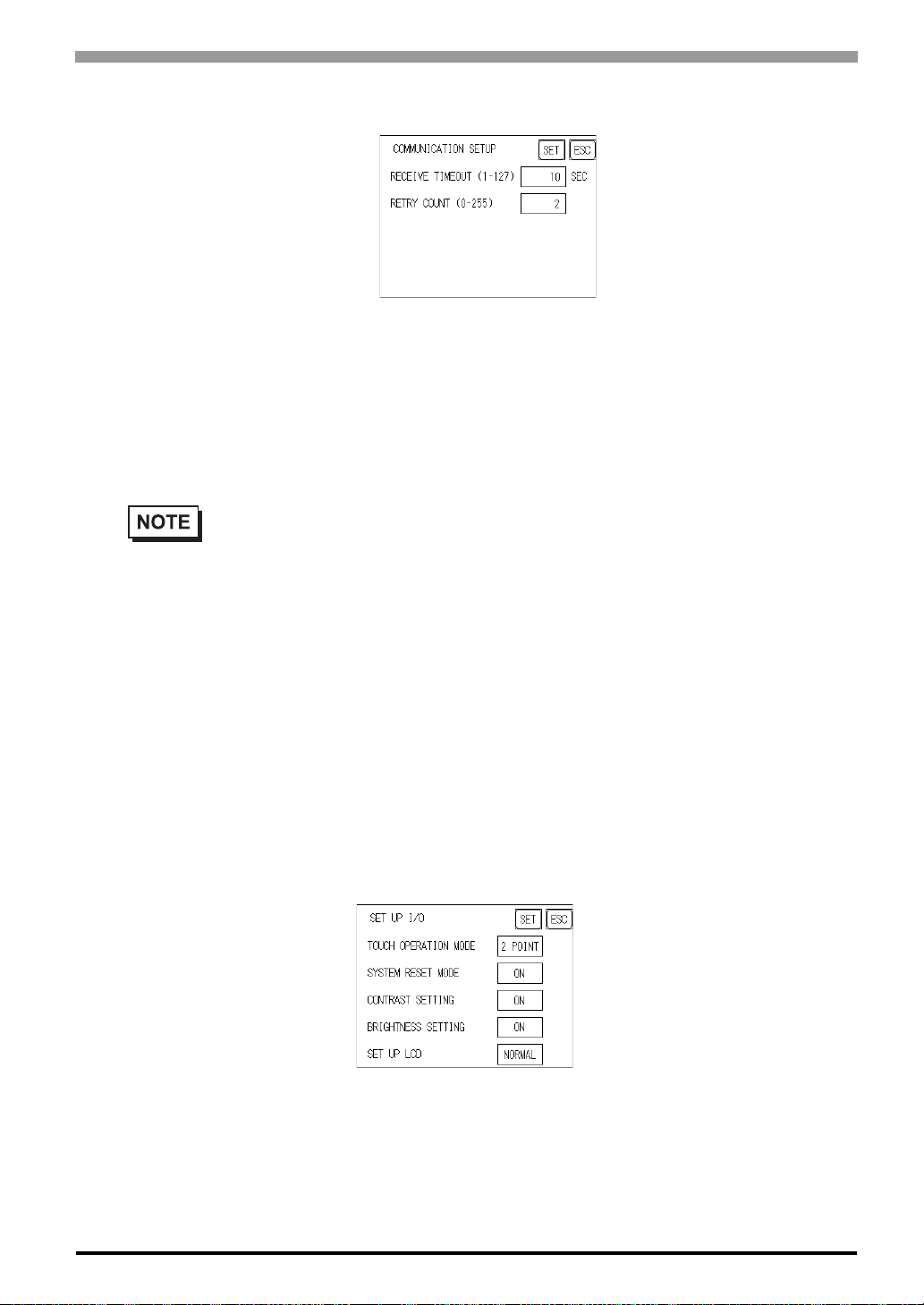
6.4.2 Communication Setup
RECEIVE TIMEOUT (1-127)
PLC sets the value used for the data reception timeout (PLC-ST).
If the cable is not connected, data communication will Timeout in one second, regardless of this setting's
value. The default is "10" seconds.
• If you transfer screens when a PLC communication error has occurred and the error is not yet
cleared, and the RECEIVE TIMEOUT value is set to 30 seconds or more, an error message may
Chapter 6 Initializing the ST
appear on your personal computer.
RETRY COUNT (0-255)
Designates how many times the ST tries to send data to the PLC when a PLC communication error occurrs.
An Error Message will appear on the ST after the ST tries to send data to the PLC the number of times set by
this option. The default is "2".
6.4.3 Set Up Touch Panel
Touch operation and Force Reset setup, and Display Device adjustments are made here. There may be diffrences on these settings depending of the ST type.
TOUCH OPERATION MODE
Designates either One Point, Two Point or No Slide. When No Slide is selected, dragging one's finger across
the touch screen will elicit no screen response, and only individually selected points will register.
6-13
Page 83
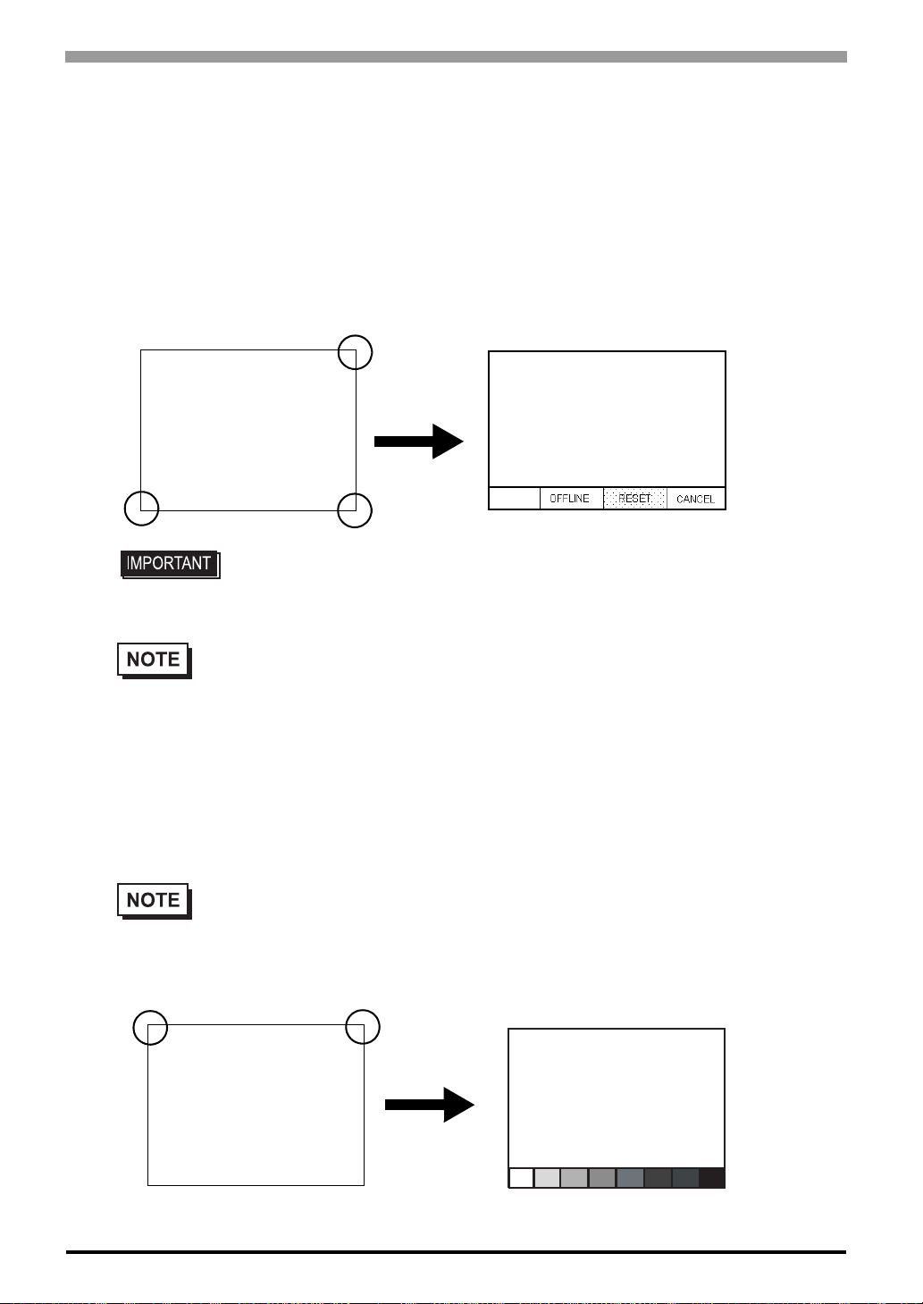
ST Series User’s Manual
SYSTEM RESET MODE
Designates whether to display or hide the Menu Bar . The Menu Bar can be displayed using the following procedure when "ON" is selected
Steps to run SYSTEM RESET
While pressing down on the bottom right corner (1) of the screen, press the upper right corner (2). At the same
time, press the bottom left corner (3) to enter the FORCE RESET Operation. To activate Reset, press the
RESET button, to transfer to OFFLINE Mode, press OFFLINE.
2
3
• FORCE RESET can occur during either RUN mode or OFFLINE mode.
• The SYSTEM RESET mode cannot be entered while the ST is starting up.
• Entering SYSTEM RESET is possible even when RUN operations
(PLC <—> ST communication) are not being performed.
1
CONTRAST ADJUSTMENT
When this option is set ON, CONTRAST ADJUSTMENTs can be made through touch input.
• Be sure to press the ST corners in the order shown. If only corner (2) is pressed OFFLINE mode
will start.
While pressing the upper right hand corner (1) of the screen, press the upper left corner (2) to enter CONTRAST ADJUSTMENT mode. Press the desired setting and the screen's contrast will change accordingly.
2
1
6-14
Bright Dark
Page 84
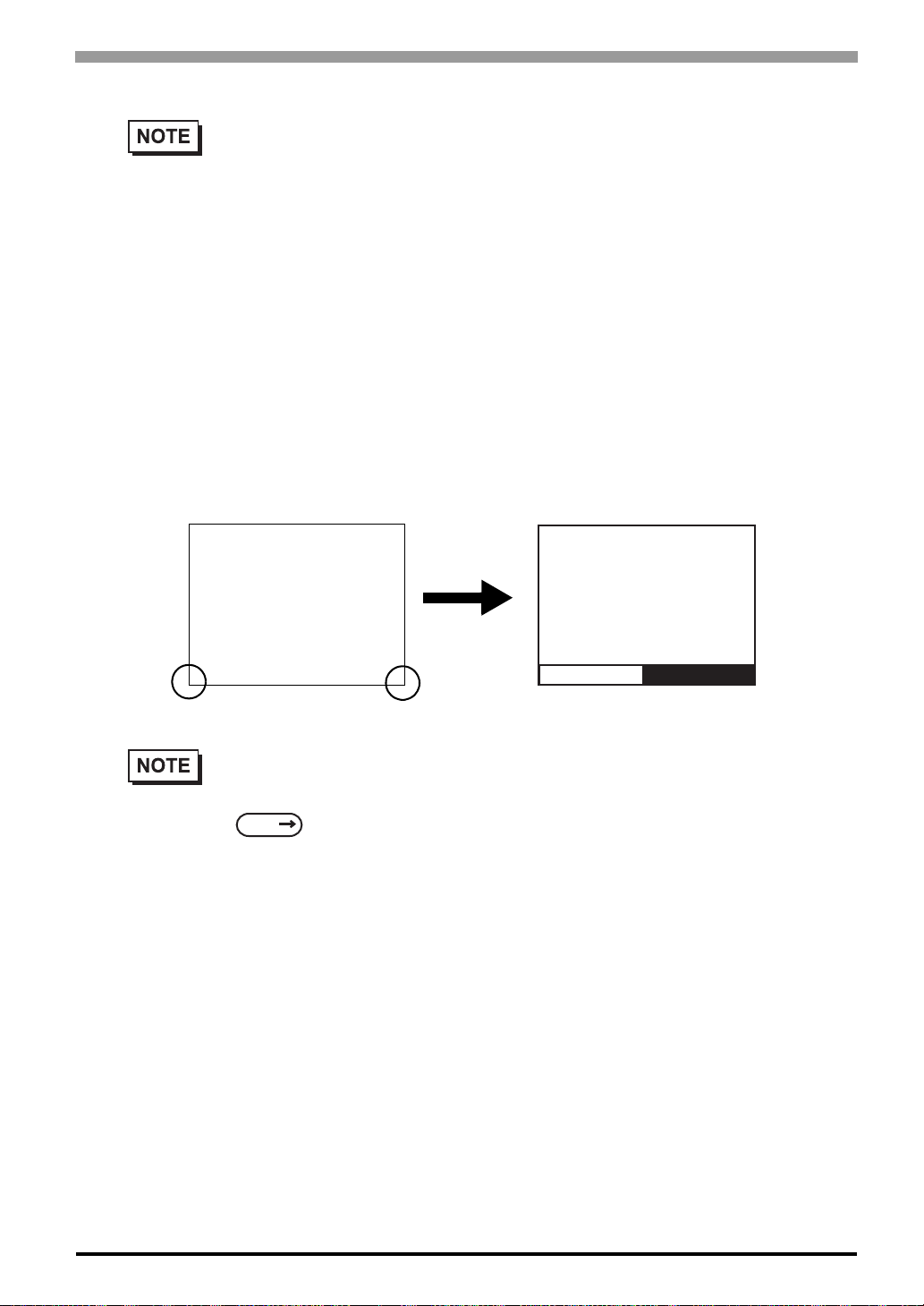
Chapter 6 Initializing the ST
• To end CONTRAST ADJUSTMENT mode, touch anywhere on the screen, except the bottom
section.
• CONTRAST ADJUSTMENT mode cannot be entered while waiting for ST to start up.
• CONTRAST ADJUSTMENTs can be made even in the middle of RUN mode (PLC<—>
ST communication).
• Regardless of a normal and reversed display, the left side of the contrast adjustment bar,
displayed at the bottom area of the screen, is always "Bright".
BRIGHTNESS ADJUSTMENT
When set to ON, brightness ADJUSTMENT can be performed via touch input. Press the bottom left corner
(2) of the screen while holding down the bottom right corner (1) to enter brightness ADJUSTMENT mode.
Touch the left-side of the bar to brighten the display; touch the right-side of the bar to dim the display. This
unit has two levels of adjustment.
Bright Dark
2
• With the ST units, reducing the display brightness may cause flicker. Adjust it by changing the
display device settings.
SEE
• To end brightness ADJUSTMENT mode, touch anywhere on the screen, except the bottom
section.
• Brightness ADJUSTMENT mode cannot be entered while the ST is starting up.
• Brightness ADJUSTMENT can be used even during RUN mode (PLC<-->ST
communication).
• Regardless of a normal and reversed display, the left side of the contrast adjustment bar,
displayed at the bottom area of the screen, is always "Bright".
• Brightness of red in ST403 cannot be adjusted.
6.4.4 Display Setup (Page 6-16)
1
6-15
Page 85
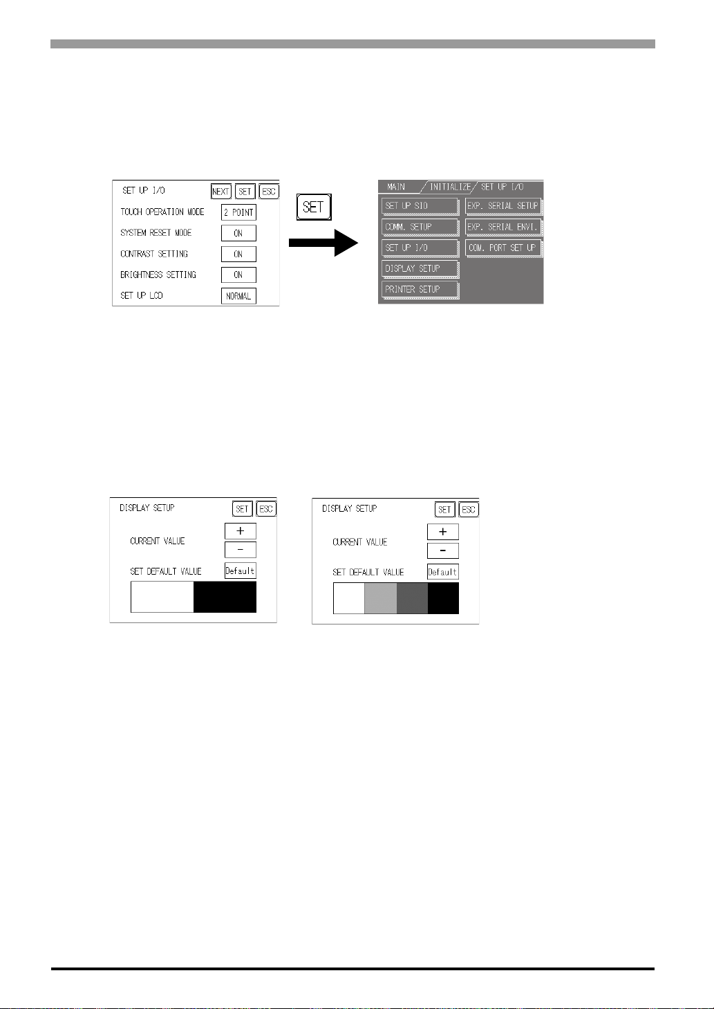
ST Series User’s Manual
SET UP LCD
To reverse the screen display colors, touch SET UP LCD on the SET UP I/O screen to change the setti ng from
"NORMAL" to "REVERSE", and then touch the "SET" key. The display color will be reversed and the previous screen will reappear.
6.4.4 Display Setup
The ST unit's screen may flicker, or there may be shadows appearing on extended display lines on the LCD
surface. In the case where the ST unit's ambient temperature becomes high, and its current brightness level is
set to low, this effect may be more pronounced. This phenomenon is however, a common attribute of LCDs
and is not a defect. To solve this, use this setting for adjusting the ST unit's brightness.
Monochrome LCD
<When using Black and White>
<When using 8 levels of gray>
CURRENT VALUE
To solve the above problem, touch "+" or "-" to adjust the brightness. You can check the actual brightness in
the preview field at the bottom of the screen. From the default value of "0" there are 18 "+" levels and 2 "-"
levels available.
SET DEFAULT VALUE
If you touch "Default", the setting returns to "0".
6.4.5 Printer Setup
This feature is not available.
6-16
Page 86
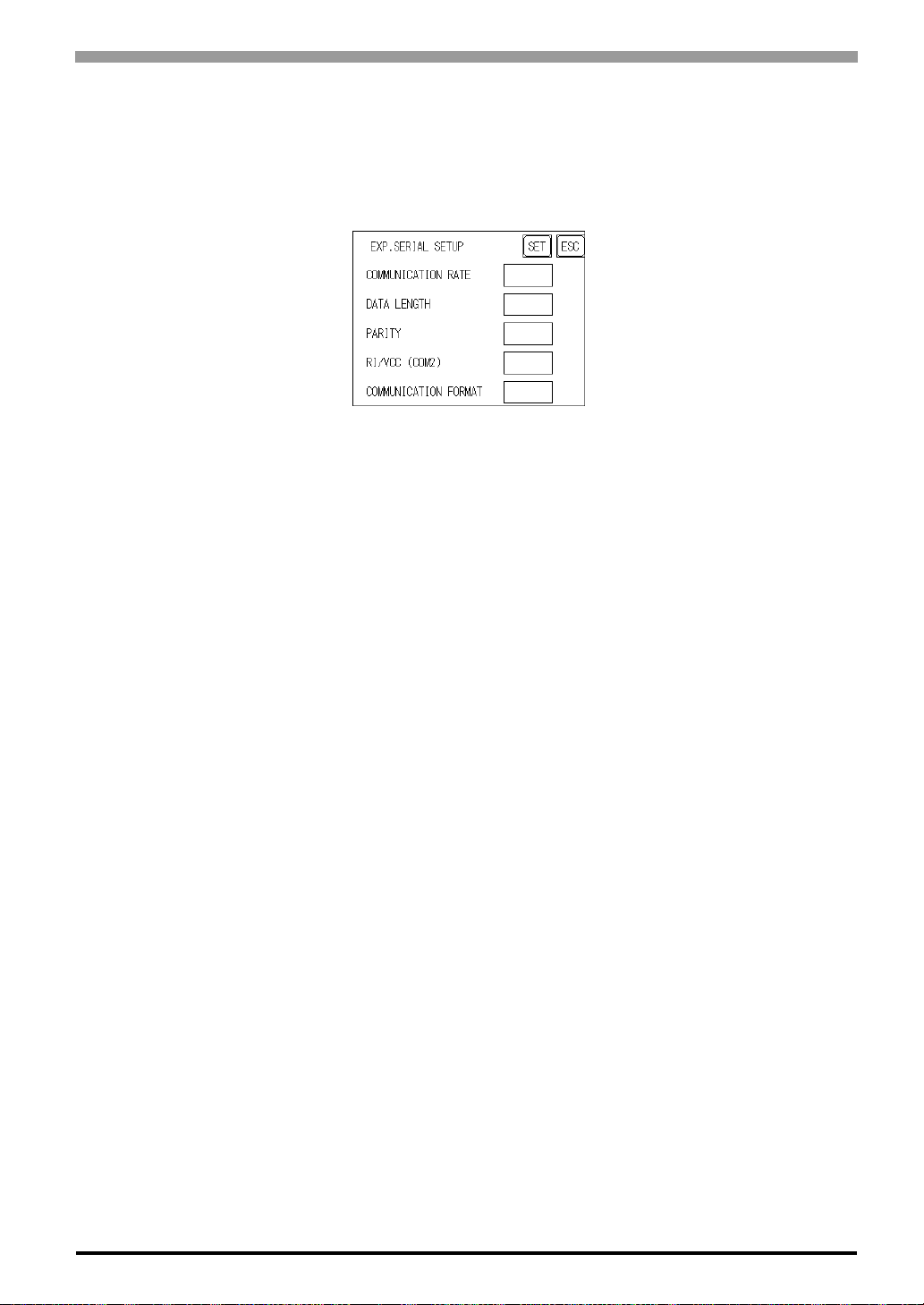
6.4.6 Expansion Serial Setup
The following explains the setup for communicating with a device connected to the Expansion Serial Interface. This setup screen will not display unless the communication protocol for the Expansion Serial Interface
(specified with “SET UP EXPANSION SIO" of the screen editor software) is transferred to the ST.
COMMUNICATION RATE
The COMMUNICATION RATE refers to the data communication speed, measured in bits per second (bps),
between the ST and the device connected to the Expansion Serial Interface.
The supported communication rates vary depending on the connected device. Refer to the instruction manual
Chapter 6 Initializing the ST
of the connected device for more information. The initial setting varies depending on the communication pro tocol for the Expansion Serial Interface being transferred.
DATA LENGTH
Set the DATA LENGTH to 7-bit or 8-bit data, and set up also the STOP BIT as either a 1-bit or 2-bit value.
PARITY
Set the parity to no parity (OFF), to ODD or to EVEN parity check.
RI/VCC (COM2)
This setting is fixed at RI and cannot be changed.
COMMUNICATION FORMAT
Set the communication format. When using ST402 unit, select either RS-422 (4 line) or RS-422 (2 line).
6-17
Page 87
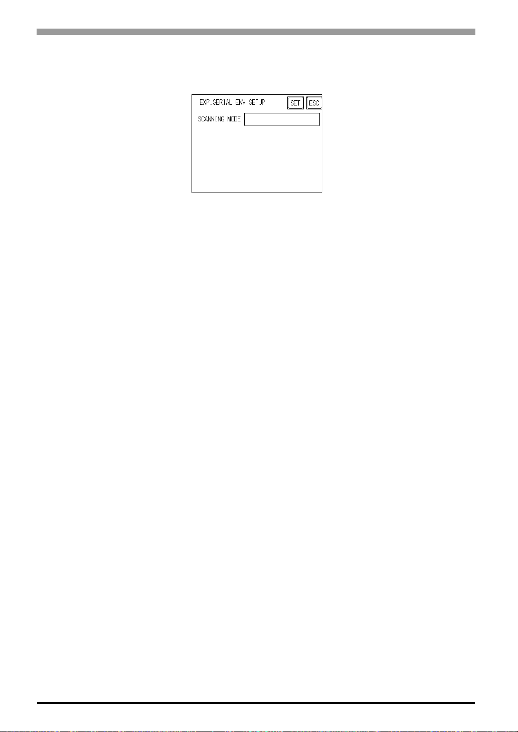
ST Series User’s Manual
6.4.7 Expansion Serial Environment Setup
Can only display the setting data entered in the screen editor software. This data cannot be changed.
6.4.8 COMMUNICATION PORT SETUP
This feature is not available.
6-18
Page 88
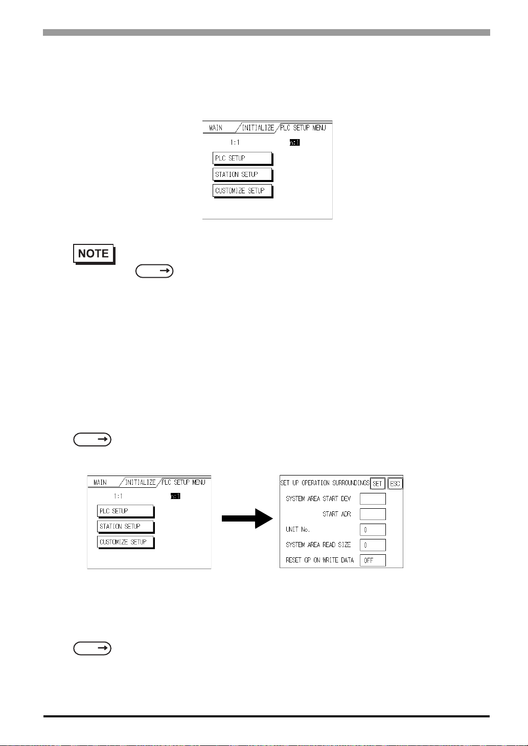
6.5 PLC Setup
Set up the ST System Area and the Unit number in this screen. Because 1:1 and n:1 ST connections utilize
different settings, confirm your connection's needs before using any settings.
• The screens that appear will depend on the PLC type you selected in the screen editor software.
• When the GP-PRO/PBIII for Windows Ver 3.0 "Simulation" feature is used, the SET UP OPER-
SEE
ATION SURROUNDINGS menu cannot be used.
GP-PRO/PBIII for Windows Device/PLC Connection Manual (includ ed with the
screen editor software)
Chapter 6 Initializing the ST
6.5.1 SET UP OPERATION SURROUNDINGS (1:1/n:1)
Enter the PLC System Data Area and the Unit Number settings here. The same options are available for both
1:1 and n:1 (Multi-link) connections.
For an n:1 (Multi-link) Connection, System Data Area settings must be setup for each ST
connected to the PLC.
SEE
GP-PRO/PBIII for Windows PLC Connection Manual (included with the screen editor software)
SYSTEM AREA START DEV/START ADR
Setup the System Data Area's Start Address. Device addresses that can be allocated will differ depending on
the type of PLC used.
SEE
GP-PRO/PBIII for Windows Device/PLC Connection Manual (included with the screen editor
software)
6-19
Page 89
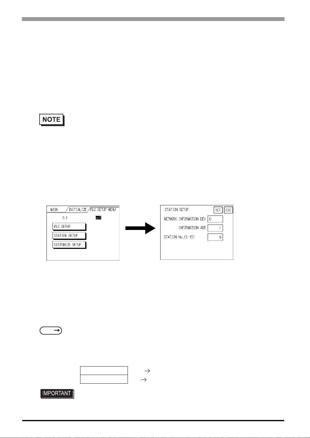
ST Series User’s Manual
UNIT No.
Enter the PLC Unit number here. Check that it matches the one set up in the PLC.
SYSTEM AREA READING
When using a Block Display Trend Graph, setup the Reading Area Size ( in word units) to match the Trend
Graph's data size. Use this feature when you wish to allocate the Reading Area in the PLC Data Register (D),
or Data Memory (DM).
• If you are not using the Reading Area, leave the 0 default values intact. This will allow you to
perform high speed data communication.
RESET ST ON WRITE DATA
Designates the mode which enables you to cancel the error from the error display when the W rite error occurs.
6.5.2 Station Setup (n:1)
The STATION SETUP, necessary for the n:1 (Multi-link) setup, checks whether correct communications run
with the connected ST System configuration.
NETWORK INFORMATION (DEV/ADR)
In the n:1 (multi-link) connection, the Network Information uses 2 words in its correspondences. These two
(2) words consist of a Connection List and a Validation List (described later in this section). These areas are
automatically allocated in the PLC's Data Register (D) or Data Memory (DM). The devices that can be allocated will vary depending on the type of PLC.
SEE
GP-PRO/PBIII for Windows Device/PLC Connection Manual (included with the screen editor
software)
PLC Data Register
Connection List
+0
Validation List
+1
PLC ST
ST PLC
6-20
• In the NETWORK INFORMATION ADR, setup the same address to all the ST's
connected to the same link unit. Furthermore, when there are 2 po rts in the connected link unit, do not make them the same address.
Page 90
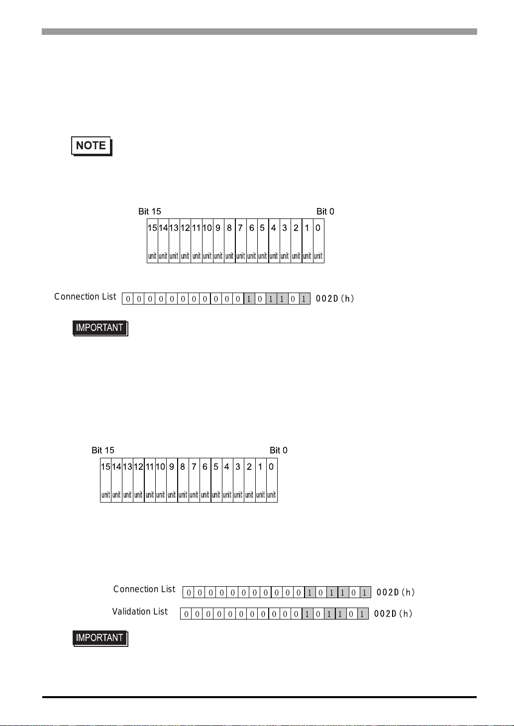
Chapter 6 Initializing the ST
Connection List
The word address for the Connection List sets up the number of ST's connected to the PLC, which must be
registered beforehand on the PLC side. When these ST's are connected to the PLC, the corresponding PLC bit
numbers for the particular ST Stations (see below) should be turned on by the PLC.
• The word address for the Connection List sets up the number of ST's connected to the PLC,
which must be registered beforehand on the PLC side. When these ST's are connected to the
PLC, the corresponding PLC bit numbers for the particular ST
Stations (see below) should be turned on by the PLC.
Bit 15 Bit 0
15
14
13
12
11
10
3
4
5
6
7
8
9
0
1
2
unit
unit
unit
unit
unit
For example, when these 4 ST units bit 0, bit 2, bit 3, bit 5 are connected, 002D (h) is written here.
Connection List
• Be certain to setup this data before running.
• Turn all bits not related to the ST OFF.
Validation List
This area responds to the correspondence from each connected ST. In the Validation List, when the same bit
numbers as the Connection List turn ON, the correspondence is accepted. The Station Numbers of the communicating STs turn their corresponding PLC bit number ON.
Bit 15 Bit 0
10
12
13
unit
unit
11
unit
14
15
unit
unit
If the correspondence between the ST and PLC is correct, the same value as in the Connection List is written
to the Validation List.
unit
9
unit
8
unit
unit
7
unit
6
unit
unit
5
unit
unit
4
unit
unit
3
unit
unit
2
unit
unit
1
unit
unit
0
unit
unit
unit
unit
unit
For example, the value 002D (h) in the Connection List, setup as the 0 bit, 2 bit, 3 bit, and 5 bit, writes to the
Validation List.
Connection List
Validation List
• When the Connection List and Validation List do not match, a COMMUNICATION ERROR occurs. Check the setup again.
• When changing the connection, first turn all the bits OFF.
6-21
Page 91
ST Series User’s Manual
STATION NO. (0-15)
This is the setup for the ST Station Number mentioned above. The setup range is from 0 to 15, and the only
other restriction is the ST STATION NO. must be unique in the system. If STATION NO.'s are repeated, a
COMMUNICATION ERROR occurs.
• The STA TION NO. i s the number alloc ated t o the p art icular ST un it. This n umbe r is not r elate d
to the Link Unit Machine number.
6.5.3 Customize Setup (n:1)
The Customize function modifies the n:1 (Multi-link) connection's communication method to make it more
effective. To run communication efficiently, the user should first determine whether they wish to have
Operation or Display priority set for the ST. Based on this, the communication response speed can be
upgraded. (However, this also depends on the screen information displayed.)
PLC PRIORITY
According to how the ST is used, select either Operation priority (OPE.) or Display priority.
• ïOperation
Setup the ST to this option when using the ST mainly as an operation panel. As a result, the ST will command better touch panel numeric input and switch response times.
Leaving the ST in this mode does not drastically influence the touch panel operation response time of
other STs. The screen display renewal cycle,however, will slow.
•ïDisplay
Setup the ST to this option when using the ST mainly as a monitor screen.
The ST will command a higher display speed as a result; however, the response time for the touch panel's
operations will slow.
• In a standard network setup, use the same setup for all connected ST's.
• To increase the display speed, be sure the addresses used are consecutive
addresses. When bit addresses are used, use consecutive to the word units.
• Speed Difference between Display Priority and Operation Priority
When using the Mitsubishi Electric Corp. A3A PLC, with a scan time of 20ms with conse cutive addresses
6-22
(80 words, not including in the System Area), the difference in reading speed i s as shown i n the f ollowing
graphs.
Page 92
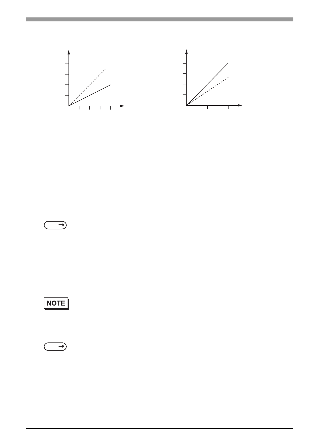
Chapter 6 Initializing the ST
TIME
Display Priority
Operation Priority
0
OPERATION RESPONSE
# of ST
TIME
Operation Priority
Display Priority
0
DISPLAY RENEWAL CYCLE
# of ST
ST TOUCH MONOPOLIZE
The monopolizing of touch panel use can be set ON or OFF. When you want to use the PLC exclusively with
a Momentary operation setup on the touch panel, turn ST TOUCH MONOPOLIZE ON.
When this setup is ON, the touch panel uses the PLC exclusively whene ver the mome ntary operation setup on
the panel is pressed. In this way , you can use the inching operation with a momentary switch. Wh en you stop
pressing the panel, exclusive use ends.
For more information about PLC exclusively
SEE
GP-PRO/PBIII for Windows Device/PLC Connection Manual (included with the screen editor software)
MONOPOLIZE TIME (0 to 2550s)
This field controls the length of time for the monopolize process when no other touch panel operations are
performed. The Monopolize process begins when the System Data Area's 7th bit of word address LS14 turns
ON, and ends either when the bit turns OFF, or when the time set here elapses.
• Pressing the touch panel in the middle of the monopolize process interrupts the MONOPOLIZE
TIME function, and ends exclusive use.
• When MONOPOLIZE TIME is set to 0, the monopolize function does not end automatically.
For further imformation about the contents of System Data Area LS6 (status) and LS14 (control),
SEE
GP-PRO/PBIII for Windows Device/PLC Connection Manual (included with the screen editor
software)
6-23
Page 93
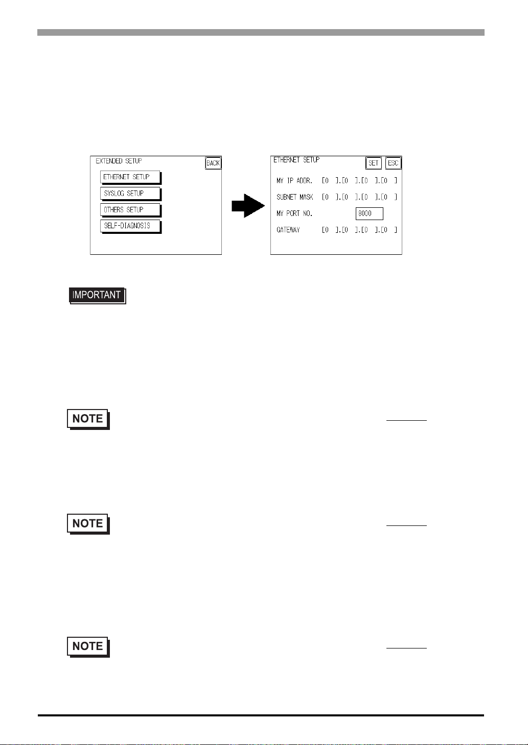
ST Series User’s Manual
6.5.4 Ethernet Setup
This menu is for Ethernet settings. This information is used as setting data during ST setup or screen transfer,
or, if the Pro-Server software is used, for the 2-Way Driver.
(Only ST403 unit.)
• Enter the “ETHERNET SETUP” settings after receiving information from your
network's system administrator.
• Be sure to enter a unique IP address, not one used for other STs or by the host.
MY IP ADDRESS
Sets up the ST’s IP address. The IP address is 32 bits and designated in four 8-bit units, entered in decimal.
• To use Ethernet networking, cl ic k o n [Initial Settings], [PLC Setup], [PLC Setup] and [Ethernet
Setup].
SUBNET MASK
Sets the subnet mask. If you are not using a subnet mask, designate “0”.
• To use Ethernet networking, clic k o n [Initial Settings], [PLC Setup], [PLC Setup] and [Ethernet
Setup].
MY PORT NO.
Sets the 2-Wa y Driver Port No. using a value from 1025 to 65526. S tarting from the value entered here, a total
of 10 consecutive ports can be used. The default setting is [8000].
6-24
• To use Ethernet networking, clic k o n [Initial Settings], [PLC Setup], [PLC Setup] and [Ethernet
Setup] and select the corresponding Ethernet protocol Port No.
Page 94
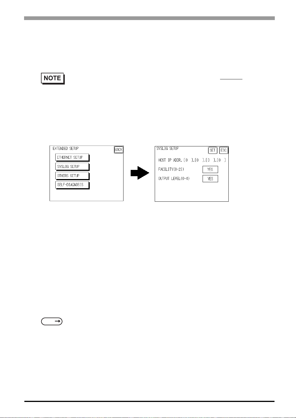
GATEWAY
Sets up the gateway’s IP address. Only a single gateway can be set up. If you are not using a gateway, enter
“0”.
• To use Ethernet networking, click on [Initial Settings], [PLC Setup], [PLC Setup] and [Ethernet
Setup].
6.5.5 SYSLOG Setup
These settings are used for outputting 2-Way driver’s operation logs. Therefore, if you are not using the ProServer software, these settings are not necessary. (Only ST unit.)
Chapter 6 Initializing the ST
HOST IP ADDRESS
Sets up the IP address of the host computer, where the 2-Way driver’s operation logs will be output.
FACILITY (0-23)
Sets up the facility.
OUTPUT LEVEL (0-4)
Sets up the output level.
For details about Pro-Server and SYSLOG,
SEE
Pro-Server with Pro-Studio for Windows Operation Manual (included in the Pro-Server with ProStudio for Windows software package)
6-25
Page 95
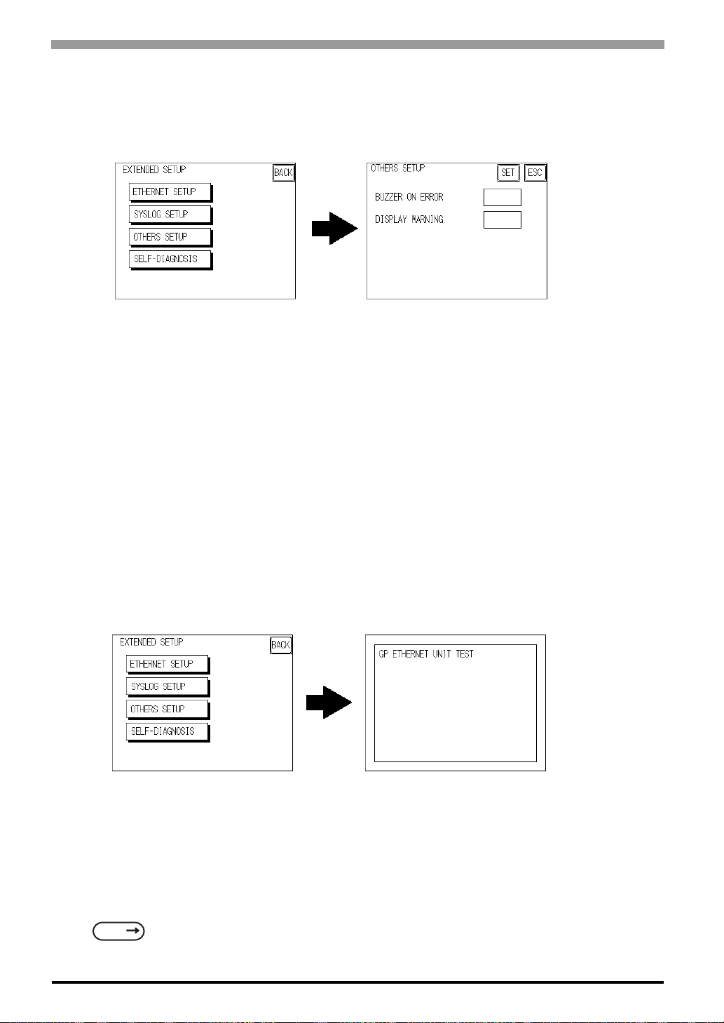
ST Series User’s Manual
6.5.6 Others Setup
Designates the ST operation performed when a 2-Way driver error occurs.
BUZZER ON ERROR
Enables/disables the buzzer sound output produced when an error related to the 2-Way driver operation
occurs.
DISPLAY WARNING
Enables/disables the warning message display used when an error related to the 2-Way driver operation
occurs.
6.5.7 Self-Diagnosis
Runs the Self Diagnosis program for the Ethernet operation. The ST must be connected to the Ethernet network prior to running this program. (Only ST403 unit.)
When there is no error detected, the message “OK” will appear. If an error is detected, the message “NG” will
appear.
6-26
Be sure that this Self Diagnosis program is used only for the Ethernet operation. If you wish to run the general
Self Diagnosis program, use [Main Menu]’s [Self Diagnosis] feature.
SEE
7.2 Self-Diagnosis (Page 7-4)
Page 96
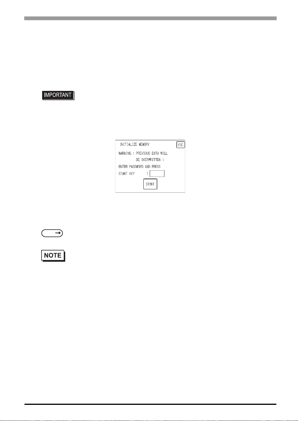
6.6 Initialize Internal Memory
This section explains how to initialize the ST's internal data.
6.6.1 Initialize ST Memory
This command erases all the ST screen data and initializes the ST's SRAM.
• You cannot cancel the Initi alization procedure after pressing the Start key.
• AIl backed up data in SRAM is lost.
• Initialization does not erase the SYSTEM SET UP, the SIO protocol, or the internal clock settings.
Chapter 6 Initializing the ST
To initialize the ST internal memory, enter the common password 1101, or the password entered in the SYSTEM SET UP screen.
For details about entering password numeric values,
SEE
5.3 Initialization (Page 5-5)
• The time required for Initialization is between 10 and 20 seconds.
6-27
Page 97
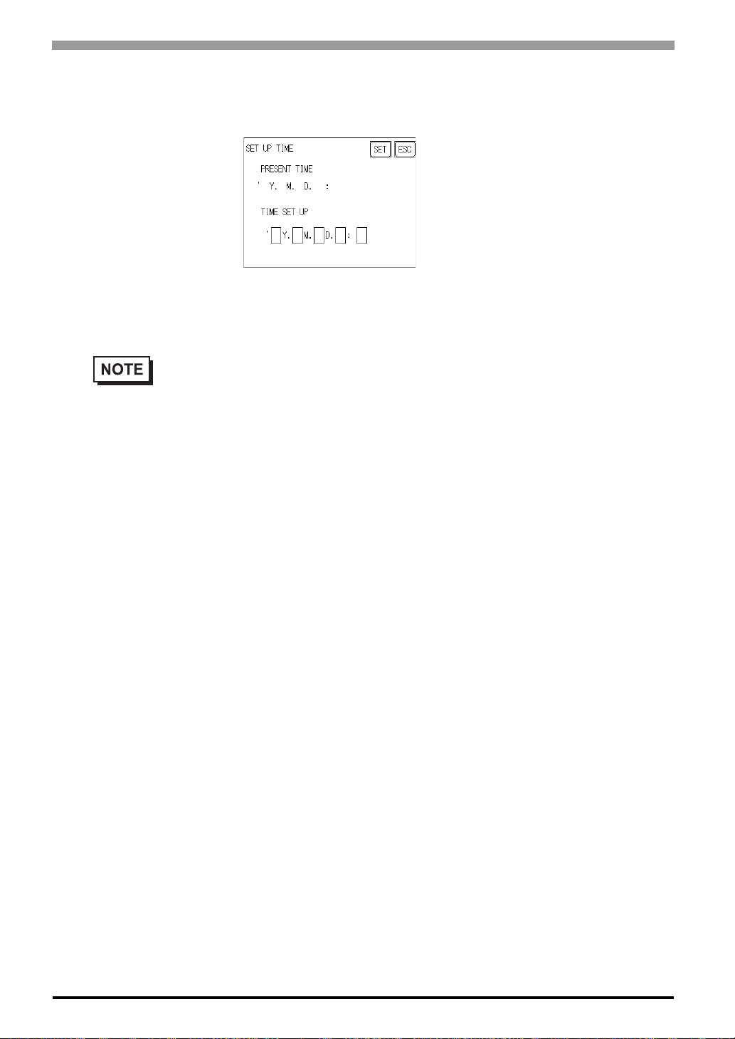
ST Series User’s Manual
6.7 Set Up Time
Sets the ST's internal clock.
SET UP TIME
Enter date and time corrections to the date and time displayed in the PRESENT TIME.
• The ST's internal clock has a slight error. At normal operating temper atures and conditions, with
the ST operating from its lithium battery , the degr ee of error is 65 seconds per month. Variations
in operating conditions and battery life can cause this error to vary from +65 to -350 seconds per
month. For systems where this degree of error will be a problem, the user should be sure to monitor this error and make adjustments when required.
6-28
Page 98
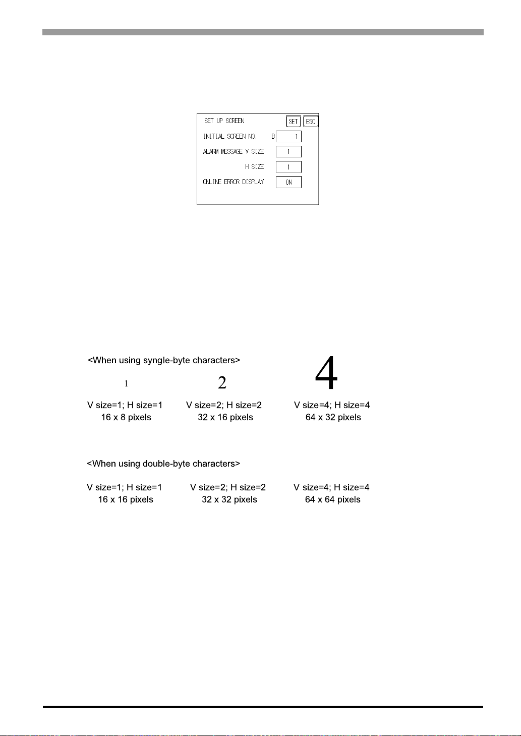
6.8 Set Up Screen
The initial screen display upon powering up, the character size when in RUN mode, and other general screen
items are setup here.
INITIAL SCREEN NO.
Set up the screen file number that will display first upon powering up. If the BIN option for DA TA TYPE OF
SCREEN NO in SYSTEM SET UP had been selected, enter a number from 1 to 8999. Or, if BCD was the
option set up, then input a number from 1 to 1999.
Chapter 6 Initializing the ST
ALARM MESSAGE
Set up the character size of the Alarm Message when the Alarm Bulletin is activated.
!
ONLINE ERROR DISPLAY
Set up whether or not error messages display during RUN mode.
"
6-29
Page 99
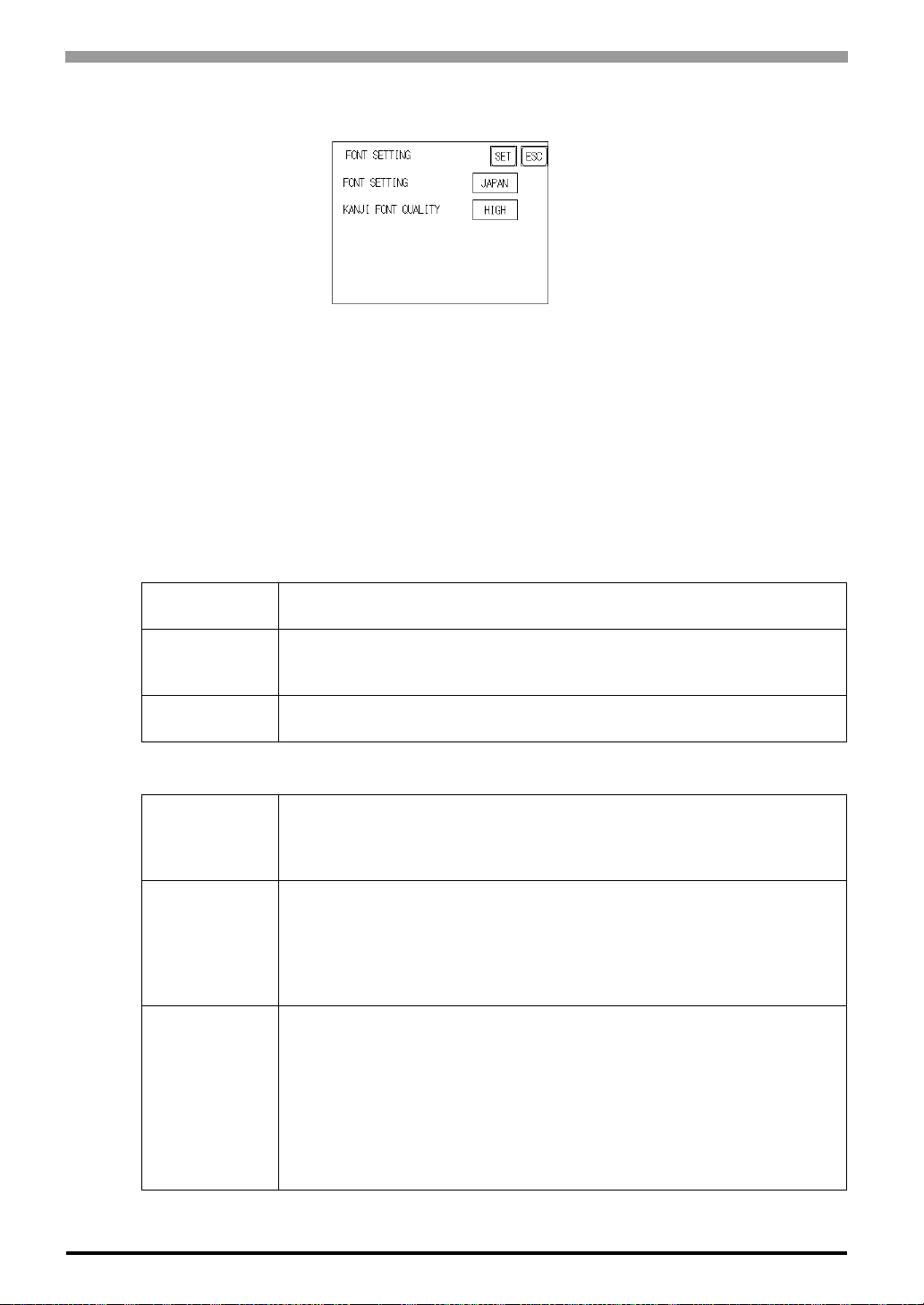
ST Series User’s Manual
6.9 Font Setting
FONT SETTING
Selects the font type displayed on the ST screen during operation.
KANJI FONT QUALITY
Designates the font display quality for enlarged characters.
When [FONT SETTING] is set to [JAPAN]
Single-byte characters will remain 8x16-dot characters when they are enlarged. Double-byte characters are
displayed as:
[Standard]
[HIGH(1)]
[HIGH(1,2)]
When [FONT SETTING] is set to any other type (i.e. CHINESE, I-ASCII, KOREA or TAIWAN)
[Standard]
[HIGH(1)]
[HIGH(1,2)]
Here, characters are displayed using 16x16-dot "blocks". When enlarged, this
font will remain a 16x16-dot character.
When enlarged to double size, Level 1 JIS Kanji Code characters are
displayed as 32x32-dot characters. Level 2 JIS Kanji Code characters remain
16x16-dot characters.
When enlarged to double size, both Level 1 and Level 2JIS Kanji Code
characters are displayed as 32x32-dot charac t ers.
Half-size (single-byte) characters are displayed as 16x8-dot characters.
Full-size characters, regardless of the display size used, will always be
displayed as 16x16-dot characters. When enlarged, this font will stay as
16x16-dot character.
All half-size (single-byte) characters (ASCII code: 21h to 7Dh, i.e. alphanumeric characters) except " ^ " and " ' " will display as high quality characters.
-16x16-dot or larger characters will display as high quality 16x16 fonts.
-32x32 or larger characters will display as high quality 32x32 fonts.
Full-sized (double-byte) characters will display as 16x16-dot characters and
remain 16x16-dot characters when enlarged.
All single-byte characters (ASCII code: 21h to 7Dh, i.e. alphanu-meric
characters) except " ^ " and " ' " will display as high quality characters.
When 16x16 dots are used for a character, it will display as a high quality
-16x16 character.
-When 32x32 or larger dots are used for a character, the character will display
as a high quality 32x32-character.
Full-sized (double-byte) characters (i.e. [KOREA], [TAIWANESE] and
[CHINESE]) will display as 32x32-dot characters when enlarged to 32x32-dot
or larger charac-ters.
6-30
Page 100

7
RUN Mode and Errors
7.1 RUN Mode
7.2 Self-Diagnosis
7.3 Troubleshooting
7.4 Error Messages
7.5 Error Message Details
7-1
 Loading...