

Page 1

LT Series
User Manual
Digital Electronics Corporation
Page 2

Preface
Thank you for purchasing the Pro-face Graphic Logic Controller LogiTouch
(hereby referred to as “LT” or “LT unit”).
Please read this manual carefully; it explains, step by step, how to use the LT
correctly and safely .
< Note >
1. It is forbidden to copy the contents of this manual, in whole or in part,
except for the user’s personal use, without the express permission of Digital
Electronics Corporation of Japan.
2. The information provided in this manual is subject to change without notice.
3. This manual has been written with care and attention to detail; however,
should you find any errors or omissions, please contact Digital Electronics
Corporation and inform us of your findings.
4. Please be aware that Digital Electronics Corporation shall not be held liable
by the user for any damages, losses, or third party claims arising from any
uses of this product.
All Company/Manufacturer names used in this manual are the registered trademarks of those companies.
© Copyright 2004, Digital Electronics Corporation
LT Series User Manual 1
Page 3

Table of Contents
Preface........................................................................................................................ 1
Essential Safety Precautions ................................................................................... 5
General Safety Precautions ................................................................................... 11
About LT Series Models ........................................................................................ 13
Package Contents ................................................................................................... 13
UL/c-UL Application Notes .................................................................................... 14
CE Marking Notes................................................................................................ 15
CNS Notes ............................................................................................................... 15
Documentation Conventions .................................................................................. 16
Software Compatibility List ................................................................................... 17
CHAPTER 1 INTRODUCTION
1.1 Prior to Operating the LT ...................................................................1-1
1.2 System Design..................................................................................... 1-2
1.2.1 System Design .......................................................................1-2
1.2.2 Product Lineup ......................................................................1-5
1.3 Accessories .......................................................................................... 1-8
CHAPTER 2 SPECIFICATIONS
2.1 General Specifications ........................................................................2-1
2.1.1 Electrical................................................................................2-1
2.1.2 Environmental ........................................................................2-2
2.1.3 Structural...............................................................................2-2
2.2 Functional Specifications.................................................................... 2-3
2.2.1 Display ..................................................................................2-3
2.2.2 Memory.................................................................................2-4
2.2.3 Control Memory....................................................................2-4
2.2.4 Clock.....................................................................................2-4
2.2.5 External Interfaces.................................................................2-4
2.3 Interface Specifications ...................................................................... 2-7
2.3.1 Serial Interface (Type C).......................................................2-7
2.3.2 Flex Network Interface (T ype B/T ype B+/Type C) ..............2-9
2.3.3 Input/Output Connector Interface
(T ype A1/T ype A2/T ype B+) .............................................2-10
2.4 Part Names and Functions................................................................ 2-19
LT Series User Manual2
Page 4

2.5 Dimensions .........................................................................................2-23
2.5.1 LT External Dimensions .....................................................2-23
2.5.2 Installation Fasteners...........................................................2-25
2.5.3 Panel Cut Dimensions..........................................................2-25
CHAPTER 3 INSTALLATION AND WIRING
3.1 Installation ...........................................................................................3-1
3.1.1 Installation Procedures ..........................................................3-1
3.2 Wiring Cautions ................................................................................... 3-6
3.2.1 Connecting the Power Cord..................................................3-6
3.2.2 Grounding..............................................................................3-8
3.2.3 Flex Network Communication Cable....................................3-9
3.2.4 I/O Signal Line Cautions .......................................................3-9
3.2.5 Installation Cautions ...........................................................3-10
3.3 Tool Connector...................................................................................3-13
3.3.1 Serial Printer Connection ....................................................3-13
CHAPTER 4 DATA TRANSFER
4.1 Data Transfer Cable ........................................................................... 4-1
4.2 Transferring Screen Data...................................................................4-2
CHAPTER 5 OFFLINE MODE
5.1 Entering OFFLINE Mode ................................................................. 5-1
5.1.1 After Plugging in the Power Cord .........................................5-2
5.1.2 From the Menu Bar...............................................................5-2
5.2 OFFLINE Mode - Main Menu .......................................................... 5-4
5.3 INITIALIZATION...............................................................................5-5
5.4 SELF-DIAGNOSIS .............................................................................5-7
CHAPTER 6 INITIALIZING THE LT
6.1 Initialization Screen............................................................................ 6–1
6.2 Initialization Items............................................................................. 6–2
6.3 SYSTEM ENVIRONMENT SETUP ............................................... 6–3
6.3.1 SYSTEM SETUP ................................................................ 6–3
6.3.2 CHARACTER STRING DATA SETUP.............................. 6–4
6.4 SET UP I/O .......................................................................................... 6–7
6.4.1 SET UP SIO ........................................................................ 6–7
6.4.2 COMMUNICATION SETUP............................................. 6–8
LT Series User Manual 3
Page 5

6.4.3 SET UP TOUCH PANEL.................................................... 6–9
6.4.4 DISPLA Y SETUP.............................................................. 6–12
6.5 OPERATION ENVIRONMENT SETUP ...................................... 6–13
6.5.1 SET UP OPERATION ENVIRONMENT........................ 6–13
6.5.2 CONTROLLER SETTINGS............................................. 6–14
6.6 INITIALIZE INTERNAL MEMORY ......................................... 6–16
6.7 SET UP TIME...................................................................................6–16
6.8 SET UP SCREEN ............................................................................. 6–17
6.9 FONT SETTING.............................................................................. 6–18
CHAPTER 7 RUN MODE AND ERRORS
7.1 RUN Mode ......................................................................................... 7–1
7.1.1 After Connecting the Power Cord ....................................... 7–1
7.1.2 Via OFFLINE Mode ........................................................... 7–2
7.2 Troubleshooting .................................................................................. 7–3
7.2.1 Possible Problems ................................................................ 7–3
7.2.2 No Display ........................................................................... 7–4
7.2.3 No LT / Host Communication .............................................. 7–7
7.2.4 T ouch Panel Does Not Respond.......................................... 7–9
7.2.5 Cannot Execute Logic Program ......................................... 7–10
7.2.6 Clock Settings Cannot be Entered ..................................... 7–10
7.2.7 Error Screens..................................................................... 7–10
7.3 SELF-DIAGNOSIS .......................................................................... 7–11
7.3.1 SELF-DIAGNOSIS ITEM LIST ...................................... 7–11
7.3.2 SELF-DIAGNOSIS - Details............................................ 7–12
7.3.3 CONTROLLER SELF-DIAGNOSIS.............................. 7–14
7.4 Error Messages................................................................................ 7–15
7.4.1 Error Message List ............................................................. 7–15
7.4.2 Error Messages - Details.................................................... 7–17
CHAPTER 8 MAINTENANCE
8.1 Regular Cleaning................................................................................ 8–1
INDEX
8.1.1 Cleaning the Display ............................................................. 8–1
8.1.2 Installation Gasket Check / Replacement............................. 8–1
8.2 Periodic Check Points ........................................................................ 8–3
8.3 Replacing the Backlight .................................................................... 8–3
LT Series User Manual4
Page 6

Preface
Essential Safety Precautions
This user manual contains a variety of safety markings for safe and correct operation of the LT unit. Please read this and any related manuals carefully to fully
understand the correct and safe usage of the LT and its features.
Safety Symbols
Please pay attention to the following safety symbols and their meanings:
Indicates situations that will definitely
DANGER
WARNING
result in severe bodily injury, death, or
major machine damage if the instructions
are not followed.
Indicates situations that may result in severe
bodily injury, death, or major machine
damage if the instructions are not followed.
Indicates situations that may result in minor
CAUTION
bodily injury or damage to the machinery if
the instructions are not followed.
DANGERS
When Designing your LT System:
• Be sure to design your LT control system so that, in the
event of a main power supply failure or an LT accident, the
user system’s overall safety integrity will be maintained. If
this is not done, incorrect output signals or an LT malfunction may cause an accident.
(1) Interlock and other circuits designed to interrupt or op-
pose normal machine movement (such as Emergency
Stop, General Protection, and forward and reverse rotation), as well as those designed to prevent machine damage (such as upper , lower, and traverse movement limit
positioning) should all be designed to be located outside of the LT.
LT Series User Manual 5
Page 7
Preface
DANGERS
(2) When the LT generates a “Watchdog Timer Error,” LT
operation will halt. Also, when Errors occur in Input/
Output control areas that the LT cannot detect, unexpected movement may occur in those areas. Therefore,
and to prevent unsafe machine movement, a “Failsafe
Circuit” should be created which is completely external
to the LT.
Section 3.2.5 – “Installation Cautions”
(3) If a problem arises with an external unit’s relay or tran-
sistor that causes an output (coil) to remain either ON
or OFF, a major accident can occur. To prevent this, be
sure to set up external watchdog circuits that will monitor vital output signals.
• Design a circuit that will supply power to the LT unit’s
I/O unit before starting up the LT. If the LT unit’s internal
program enters RUN mode prior to the I/O unit’s load control power turning ON, an incorrect output (signal) or malfunction could cause an accident.
• Design a user program that ensures the safety of the user’s
system, in the event of an LT display or control error, or
either a data transmission error or power failure between
the LT and a connected unit. These types of problems can
lead to an incorrect output (signal) or malfunction, resulting in an accident.
• Do NOT use the LT as a warning device for critical alarms
that can cause serious operator injury, machine damage,
or production stoppage. Use stand-alone hardware and/or
mechanical interlocks to design alarm indicators and their
control/activator units.
• Do NOT use LT touch panel switches to perform operator
safety-related or important accident-prevention operations.
These operations should be performed by separate hardware switches to prevent operator injury and machine damage.
6
LT Series User Manual
Page 8
Preface
DANGERS
• Design your system so that equipment will not malfunction
due to a communication fault between the LT and its host
controller . This is to prevent any possibility of bodily injury
or material damage.
• The LT is not appropriate for use with aircraft control de-
vices, medical life-support equipment, central trunk data
transmission (communication) devices, or nuclear power
control devices, due to their inherent requirements of extremely high levels of safety and reliability.
• When using the LT with transportation vehicles (trains, cars,
and ships), disaster and crime prevention devices, various
types of safety equipment, and medical devices that are
not life-support related, use redundant and/or failsafe system designs to ensure the proper degree of reliability and
safety.
WARNINGS
• Unlike the LT unit’ s “Standby Mode,” after the L T unit’ s back-
light burns out, the touch panel is still active. If the operator fails to notice that the backlight is burned out and
touches the panel, a potentially dangerous machine operation error can occur. Your backlight is burned out if:
• your L T is not set to “Standby Mode” and the screen has
gone blank
• your LT is set to “Standby Mode,” but touching the screen
does not cause the display to reappear
To prevent an accidental machine operation error, Pro-face
recommends that you use the L T unit’s “USE T OUCH P ANEL
AFTER BACKLIGHT BURNOUT” feature, to automatically
detect a burnout and disable the touch screen.
Section 6.4.3 – “Set Up Touch Panel”
LT Series User Manual 7
Page 9

Preface
WARNINGS
Installation Warnings:
• High voltage runs through the LT. To prevent an electrical
shock, do NOT disassemble the LT for any reason other
than to replace the backlight.
• Do NOT modify the LT unit. Doing so may cause a fire or an
electrical shock.
• Do NOT use the LT in an environment where flammable
gases are present. Doing so may cause an explosion.
Wiring Warnings:
• To prevent electrical shock or equipment damage, unplug
the LT unit’s power cord from the power supply prior to
installing or wiring the LT.
• After completing any LT wiring work, be sure the terminal
block’s protective plastic cover is reattached. If this cover
is not reattached, an electrical shock could easily occur.
• High voltage runs through the LT. Except for changing the
backlight, do NOT attempt to open the LT, since there is a
possibility of an electrical shock.
• Do NOT use power levels with the LT that are higher or
lower than the LT unit’s specified power range. Doing so
may cause a fire, electrical shock, or LT damage.
• Do NOT operate or store the LT in areas where flammable
gases are present and may cause an explosion.
Operation and Maintenance Warnings:
• NEVER touch a live power terminal. Doing so could cause
an electrical shock or a machine malfunction.
• To prevent an electrical shock, unplug the LT unit’s power
cord before either cleaning the LT or attaching/detaching
the power terminal attachment screws.
• When replacing the LT unit’s backlight, be sure to unplug
the unit’s power cord to prevent an electrical shock, and
wear safety gloves to prevent burns.
8
LT Series User Manual
Page 10

Preface
WARNINGS
• The LT uses a lithium battery to back up its internal clock
and to control memory data. If the battery is incorrectly replaced (reversed positive [+] and negative [-] ends), the battery may explode. Therefore, Pro-face recommends that you
contact your local LT distributor for instructions before replacing or changing the battery.
• Do not attempt to modify the L T unit’s internal parts or wir-
ing in any way , since this may lead to either electrical shock
or fire.
CAUTIONS
Wiring Layout Cautions:
• To prevent an LT unit malfunction due to excessive noise,
isolate all LT input/output signal lines from all power wiring or power cables via a separate wiring duct.
Installation Cautions:
• To reduce the risk of incorrect input or output signals, be
sure that any data cables attached to the LT unit’s connector make full contact with the connector pins.
General Wiring Cautions
• To prevent electrical shocks or malfunctions, be sure the
LT unit’s FG (earth) wire is grounded as follows:
(1) maximum grounding resistance: 100
(2) minimum grounding wire diameter: 2mm
• The L T unit’ s wiring should be checked to confirm that both
ΩΩ
Ω
ΩΩ
2
the operating voltage and wiring terminal locations are correct. If either the voltage or the wiring terminal location is
incorrect, it can cause a fire or accident.
• Be sure to secure all wiring terminal screws with the des-
ignated torque. Screws and terminals that become loose
can cause a short circuit, fire, or accident.
LT Series User Manual 9
Page 11
Preface
CAUTIONS
• Be sure that metal filings or wiring remnants do not fall
inside the LT, since they can cause a fire, accident, or malfunction.
LT Operation and Maintenance Cautions
• Be sure to read the LT unit’s manual and online help information carefully before performing program changes, entering forced output, or using the RUN, STOP, or PAUSE
commands while the LT is in operation. Mistakes concerning the use of these items can cause a machine accident or
damage.
• The liquid crystal panel contains a powerful irritant. If, for
any reason, the panel is damaged and this liquid enters
your eyes, flush your eyes for 15 minutes with running water
and contact a physician immediately.
LT Unit Disposal Cautions
• The L T unit should be disposed of in a manner appropriate
to, and in accordance with, the user country’s industrial
machinery disposal standards.
10
LT Series User Manual
Page 12

Preface
General Safety Precautions
• Do NOT strike the touch panel with a hard or pointed object, or press on
the touch panel with too much force, since it may damage the touch
panel or the display.
• Do NOT install the LT where the ambient temperature can exceed the
allowed range. Doing so may cause the L T to malfunction or shorten its
operation life.
• Do NOT restrict or limit the LT unit’s naturally-occurring, rear-face ventilation, and do NOT store or use the LT in overheated areas.
• Do NOT store or use the LT unit in areas where large, sudden temperature changes can occur. These changes can cause condensation to form
inside the unit, which can cause possible unit malfunctions.
• Do NOT allow water, liquids, metals, or charged particles to enter inside
the LT unit’s outer casing, since they can cause either an LT malfunction or an electrical shock.
• Do NOT store or use the L T in direct sunlight, or in excessively dusty or
dirty environments.
• Do NOT store or use the LT in an environment where shaking or excessive vibration can occur.
• Do NOT store or use the LT where chemicals (such as organic solvents
and acids) can evaporate, or in environments where chemicals and acids are present in the air.
Corrosive chemicals: acids, alkalines, liquids containing salt
Flammable chemicals: organic solvents
• Do NOT use paint thinner or organic solvents to clean the LT.
• Do NOT store or operate the LCD display in areas that receive direct
sunlight, since the sun’s ultraviolet (UV) rays may cause the quality of
the LCD to deteriorate.
• Storing this unit in areas at temperatures that are lower than is recommended in this manual’s specifications may cause the LCD panel’s liquid to congeal, which may damage the panel. Conversely , if the storage
area’s temperature becomes higher than the allowed level, the LCD
panel’s liquid will become isotropic, causing irreversible damage to the
LCD. Therefore, be sure to store the panel only in areas where temperatures are within the ranges specified in this manual.
• Due to the possibility of unexpected accidents, be sure to back up the
LT unit’s screen data regularly.
LT Series User Manual 11
Page 13

Preface
About the LT Unit’s Display Panel
• The data that is currently displayed on the L T unit's screen, the screen’ s
brightness, and the LT unit’s voltage
of
Contouring — a wavelike pattern that is created when some parts of
the screen are brighter than others.
• The minute, dark and light grid-points on the display panel’s surface is
part of the LT unit’s design and are not defects.
• Extended shadows, or “Crosstalk”, may appear on the sides of screen
images. This is normal for an LCD panel.
• Sometimes the display area may look as if the display colors have
changed.
• Displaying a single image for long periods of time can cause an afterimage to remain when the screen display is changed.
This is a common attribute of LCDs and is not a defect.
*1
each affect the screen’s intensity
To prevent this effect:
Use the LT unit’s “Standby Mode,” which automatically turns the
screen OFF when no input is entered within a specified period of
time.
Section 6.3.1 – “System Setup”
• Write “FFFFh” to the System Data Area’s “Screen Display Off” address
to turn the screen display OFF when the following actions are not performed within the user-specified period of time.
• Change Screen
• Touch Screen
• Alarm Display
Do NOT display any single screen for a long period of time. Try to
change the screen display periodically.
1 Operating the LT unit in the lower range of its allowable operating voltage may
affect the intensity of contouring.
2 The following addresses assume all System Data Area settings are entered. If they
are
not all entered, the correct word address may be different, since the following
addresses are relative, not fixed, addresses.
With the Direct Access Method — use System Data Area word address +9
With the Memory Link Method — use System Data Area word address +12
*2
12
LT Editor Device Connection Manual (included with the LT Editor software)/GP-PRO/PBIII Device/PLC Connection Manual
(included with the C-Package software)
LT Series User Manual
Page 14

About LT Series Models
The LT Series refers to the following LT model numbers:
LT Se ries
Name Model Description
Preface
LT Type A1 GLC150-BG41-XY32SK-24V
LTC Type A1 GLC150-SC41-XY32SK-24V
LT Type A2 GLC150-BG41-XY32SC-24V
LT Type B GLC150-BG41-FLEX-24V Flex Network I/F
LT Type B+ GLC150-BG41-XY32KF-24V
LTC Type B+ GLC150-SC 41-XY32KF-24V
LT Type C GLC150-BG41-RSFL-24V Flex Network I/F and SIO I/F
16-point Input Sink/Source and 16-point transistor
Output Sink type
16-point Input Sink/Source and 16-point transistor
Output Source ty pe
16-point Input Sink/Source and 16-point transistor
Output Sink, and Flex Network I/F type
Package Contents
Please verify that the LT unit’s packing box contains all the items listed below.
LT Unit (1)
Installation Gasket (1)
Installation Guide (1)
Installation
Guide
Installation Fasteners
*1
(4/set)
Flex Network I/F Connector (1)
(Included with LT Type B/B+/C/LTC
Type B+ units only)
Special care and attention have been given to the packaging of this LT unit. However, if any of the items are damaged or missing, please contact your local LT
distributor immediately for prompt service.
1 The LT Series User Manual (this manual) is sold separately.
LT Series User Manual 13
Page 15

Preface
UL/c-UL Application Notes
The GLC150-**41-****-24V units are UL/c-UL listed products. (UL file No. E214883),
however the GLC150-BG41-XY32KF-24V/GLC150-SC41-XY32KF-24V are listed with
file no. E182139.
These units conform as products to the following standards:
UL 508, Industrial Control Equipment
UL 1604, Electrical Equipment for use in Class 1 & 2 – Division 2, or Class 3
Hazardous Locations.
CAN/CSA-C22.2, No. 1010-1
(Safety requirements for electrical equipment for measurement, control and laboratory use)
GLC150-BG41-XY32SK-24V (UL Registration Model: 2980036-01)
GLC150-SC41-XY32SK-24V (UL Registration Model: 3280027-11)
GLC150-BG41-FLEX-24V (UL Registration Model: 2980036-02)
GLC150-BG41-RSFL-24V (UL Registration Model: 2980036-03)
GLC150-BG41-XY32SC-24V (UL Registration Model: 2980036-04)
GLC150-BG41-XY32KF-24V (UL Registration Model: 3080060)
GLC150-SC41-XY32KF-24V (UL Registration Model: 3280027-12)
<Cautions>
• The LT unit must be used as a built-in component of an end-use product.
• The LT unit must be installed with the front face facing outwards.
• If this unit is installed so as to cool itself naturally, be sure to install it in a
vertical panel. Also, be sure that the LT unit is mounted at least 100 mm away
from any adjacent structures or equipment. If these requirements are not met,
the heat generated by the LT unit's internal components may cause the unit to
fail to meet UL/c-UL standard requirements.
• Separate the LT unit's power and signal lines from the main power supply via
double or reinforced insulation.
UL1604 Conditions of Acceptability and Handling Cautions:
1. Power, input and output (I/O) wiring must be in accordance with Class I,
Division 2 wiring methods - Article 501- 4(b) of the National Electrical Code,
NFPA 70 within the United States, and in accordance with Section 18-152 of
the Canadian Electrical Code for units installed within Canada.
2. Suitable for use in Class I, Division 2, Groups A, B, C and D, Hazardous
Locations.
14
3. WARNING: Explosion hazard - substitution of components may impair suitability for Class I, Division 2.
4. WARNING: Explosion hazard - when in hazardous locations, turn power OFF
before replacing or wiring modules.
5. WARNING: Explosion hazard - do not disconnect equipment unless power has
been switched OFF, or the area is known to be free of hazards.
LT Series User Manual
Page 16
Preface
CE Marking Notes
The GLC150-**41-****-24V units are CE marked products that conform to EMC
directives EN55011 class A and EN61000-6-2.
Conformance Standards to EMC Directives
The EN61000-6-2 standard requires that products connected to an unprotected DC
line have 500V resistance (normal mode/common mode) in accordance with the
61000-4-5 surge test.
However, note that the power supply for the DIO of the LT unit is designed on the
assumption that it is connected to a protected DC power-supply line. Therefore,
the surge test included in this specification is inapplicable.
This LT unit’s 24V Power Input for DIO is not equipped with protection against
lightning surges. Therefore, it is not lightning surge resistant. To make your LT
unit or system compliant with EMC directives, connect the LT unit to surge
protected power, and set up sur ge resistance for your LT unit or overall system.
For example, when an LT unit mounted to a control panel is supplied DC24V
power in accordance with the EMC directive, this LT unit’s input side is protected
from power surges.
CNS Notes
The GLC150-BG41-****-24V units comply with the following CNS standards:
• CNS 13438 (Class A)
<Caution>
The LT is an Industrial Device (Class A Device). Home use of this device may
cause radio wave interference with nearby devices. If interference does occur,
please try a variety of countermeasures to solve the problem.
LT Series User Manual 15
Page 17

Preface
Documentation Conventions
The list below describes the documentation conventions used in this manual.
Symbol Meaning
Indicates important information or procedures that must be
followed for correct and risk-free software/device operation.
LT or
LT unit
LT Editor
C-Package
External
Dev ice
*1
LT Type A1/Type A2/Type B/Type B+/Type C,
LTC Type A1/Type B+
Indicates the LT Editor software.
Indicates Screen Creation software GP-PRO/PBIII and Logic
Program Development software Pro-Control Editor.
Indicates peripheral devices (such as Temperature Controllers,
Inverters, etc.), but does not include Flex Network and DIO units.
Provides useful or important supplemental information.
Provides useful or important supplemental information.
Cross-references to useful or important supplemental
information.
16
LT Series User Manual
Page 18

Preface
Software Compatibility List
The LT Series of operator interfaces can use either of the following software
packages to create both screens and logic programs.
• GP-PRO/PBIII C-Package03 or later
• LT Editor
However, the LT color-type operator interfaces must use the GP-PRO/PBIII C-
Package03 or later software. LT Editor software cannot be used.
Also, for LT Type B+ Series units, the LT Editor version must be 1.04 or higher.
Please be sure to read the following table prior to creating your screens and logic
programs, as the software that can be used will vary depending on the type of unit.
Model Number LT Editor C-Package 03 or la ter
GLC150-BG41-XY32SK-24V
GLC150-SC41-XY32SK-24V
GLC150-BG41-XY32SC-24V
GLC150-BG41-FLEX-24V
GLC150-BG41-XY32KF-24V
GLC150-SC41-XY32KF-24V
GLC150-BG41-RSFL-24V
OO
XO
OO
OO
O
(Version 1.04 or later)
XO
OO
O
LT Series User Manual 17
Page 19

Preface
Memo
18
LT Series User Manual
Page 20

1. Prior to Operating the LT
2. System Design
3. Accessories
Chapter
1 Introduction
1.1 Prior to Operating the LT
Use the following steps when creating projects for the LT unit.
1. Preparation – Before using the LT, be sure that you have all required hard-
ware, and have read all specification, wiring, and installation
information.
Chapter 2 – “Specifications” and Chapter 3 – “Installation and
Wiring”
2. Design – Design your LT screens and create a logic program.
3. Install the LT Editor/C-Package – Install the LT Editor/C-Package software
in your PC.
LT Editor CD Jacket, C-Package CD Jacket
4. Develop Logic Program – Use the LT Editor/C-Package software to develop a
logic program and set the operation mode.
LT Editor Operation Manual – Logic Programming Guide, ProControl Editor Operation Manual/User Manual (included with the
C-Package software)
5. Create Screen / Run Screen Setup – Use the LT Editor software to set up the
screen and parts according to your screen design.
LT Editor Operation Manual – Screen Creation Guide, GP-PRO/
PBIII Operation Manual (included with the C-Package software)
6. Transfer Screen Data and Logic Pr ogram – Use the LT Editor/C-Package
software to transfer your screen data and logic program to the LT
unit.
LT Editor Operation Manual – Screen Creation Guide, GP-PRO/
PBIII Operation Manual (included with the C-Package software)
7. Monitor Logic Program – Use the LT Editor/C-Package software's monitor
feature to check that your logic program operates correctly.
LT Editor Operation Manual – Logic Programming Guide, ProControl Editor Operation Manual (included with the C-Package
software)
8. Initialize – Set up the LT unit's Initial Settings according to your operation needs.
Chapter 5 – “Initializing the LT”, LT Editor Device Connection
Manual and GP-PRO/PBIII Device/PLC Connection Manual
(included with the C-Package software)
9. Operation – Connect the LT to an external device and begin operation.
LT Editor Device Connection Manual, GP-PRO/PBIII Device/
PLC Connection Manual (included with the C-Package software)
Each LT Editor/C-Package manual referenced above is included with the LT Editor
software, and is also available as a PDF file on the CD-ROM.
LT Series User Manual 1–1
Page 21

Chapter 1 – Introduction
1.2 System Design
1.2.1 System Design
There are five (5) L T series unit types: T ype A1, Type A2, T ype B, T ype B+ and T ype C.
LT Se ries
Name Model Description
LT Type A1 GLC150-BG41-XY32SK-24V
LTC Type A1 GLC150-SC41-XY32SK-24V
LT Type A2 GLC150-BG41-XY32SC-24V
LT Type B GLC150-BG41-FLEX-24V Flex Network I/F
LT Type B+ GLC150-BG41-XY32KF-24V
LTC Type B+ GLC150-SC 41-XY32KF-24V
LT Type C GLC150-BG41-RSFL-24V Flex Network I/F and SIO I/F
Stand-alone 32 point I/O System (Type A1/Type A2)
16-point Input Sink/Source and 16-point transistor
Output Sink type
16-point Input Sink/Source and 16-point transistor
Output Source ty pe
16-point Input Sink/Source and 16-point transistor
Output Sink, and Flex Network I/F type
The LT can independently control up to 32 external I/O units (DC 24V 16-point
Input/16-point Output).
LT
I/O Units
Flex Network System (Type B)
Connecting Flex Network units to the LT unit allows you to use the L T to control
remote I/O.
Flex Network I/O units are connected to the LT via the Flex Network I/F unit,
which is equipped with 2 channels — CH1 and CH2. Through these channels, the
LT can send identical communication data. Y ou can select either one of these
channels, or both, when sending communication data to the external I/O units.
Using a single channel enables you to send communication data to 31 I/O units via
one channel, and to 32 I/O units via the other channel. Therefore, using both
channels, the LT can communicate with a total of 63 Flex Network I/O units.
LT Series User Manual1–2
Page 22

Chapter 1 – Introduction
LT
CH1
CH2
Flex
Network
Flex
Network
Units
For detailed information about the Flex Network, refer to
the Flex Network User Manual.
32 Point I/O + Flex Network System Design (Type B+)
The LT unit can independently control up to 32 I/O units. (DC24V Input 16 points/
Output 16 points Sink)
Connecting Flex Network I/O units to the LT allows the LT to control any remote I/O
unit. When connecting the I/O unit, two channels are available — CH1 and CH2. Each
channel outputs the same data and can be used for data communication.
When using a single channel, the maximum number of I/O units that can be
connected is 30, and when using a second channel, the number increases by 32,
for a total of 62 I/O units.
Since this unit’s 32 point I/O occupies one of the units in the Flex Network system, the total number of units available on Channel 1 is 31, and on Channel 2 is
32, for a total of 63 units.
Flex Network
LT
I/O Units
CH1
CH2
Flex Network
For detailed information about the Flex Network, refer to the Flex
Network User Manual.
LT Series User Manual 1–3
Page 23

Chapter 1 – Introduction
Flex Network / SIO System Design (Type C)
Connecting Flex Network I/O units to the LT allows the LT to control any remote I/O
unit. When connecting the I/O unit, two channels are available — CH1 and CH2. Each
channel outputs the same data and can be used for data communication.
When using a single channel, the maximum number of I/O units that can be
connected is 31, and when using a second channel, the number increases by 32,
for a total of 63 I/O units.
The LT unit's serial interface allows you to connect to external devices such as
temperature controllers or inverters.
SIO
LT
Flex Network
CH1
CH2
Flex Network
Temperature Controller,
Inverter, etc.
For detailed information about the Flex Network, refer to the Flex
Network User Manual.
For information about external devices, refer to the LT Editor Device Connection Manual (included with the LT Editor softwar e), GPPRO/PBIII Device/PLC Connection Manual (included with the C-
Package software) .
LT Series User Manual1–4
Page 24

Chapter 1 – Introduction
1.2.2 Product Lineup
The following diagram represents the main selection of devices connectable to the
LT.
Screen Editing Environment
LT Operating Environment
c
Data Transfer Cable
GPW-CB02
USB Data
Transfer Cable
GPW-CB03
Bar Code Reader
(limited to tested types)
DIO Connector
GLC100-DIOCN01
d
DIO Connector
GLC-DIOCN02
*3
*4
LT Editor Integrated
Development Software
Personal
Computer
*1
Conversion Cable
(user-created)
DIO Cable
Flat Cable
*2
Printer
(Commercially available
type)
i
I/O Units,
Lamps,
LEDs,
Sensors,
Switches,
etc.
f
DIO Cable (w/connector)
CGP070-ID11-M (3.5m)
GLC000-DIOCB11-MS (3.5m)
e
Flex Network Communication Cable
FN-CABLE2010-31-MS (10m)
FN-CABLE2050-31-MS (50m)
FN-CABLE2200-31-MS (200m)
RS-422 Connector
Terminal Adapter
GP070-CN10-0
RS-232C Cable
GP410-IS00-0
RS-422 Cable
GP230-IS11-0
GP230-IS12-0
(for Multi-link cable)
*5
*5
*5
*5
h
Flex Network
units (I/O,
Analog, etc.)
g
External Devices
(Temperature
Controllers,
Inverters, etc.)
*6
LT Series User Manual 1–5
Page 25

Chapter 1 – Introduction
1 For the range of compatible PCs, refer to the
2 The software that can be used will vary depending on the type of unit.
3 Software version limitations apply.
4 See Page 1-7 for recommended units.
5 Certain types and models of external devices cannot be connected.
6 For information about compatible external device types, refer to the
LT Editor CD Jacket (included with the LT Editor software),
C-Package CD Jacket
Software Compatibility List
For details, USB Data Transfer Cable Installation Guide.
LT Editor Device Connection Manual (included with the LT Editor
software), GP-PRO/PBIII Device/PLC Connection Manual (in-
cluded with the C-Package software)
LT Editor Device Connection Manual (included with the LT Editor
software), GP-PRO/PBIII Device/PLC Connection Manual (included with the C-Package software)
LT Interfaces
c Tool Connector
d I/O Connector (Type A1/Type A2/Type B+)
e Flex Network Interface (Type B/Type B+/Type C)
f Serial Interface (Type C)
External Device Interface (for Temperature Controllers, Inverters, etc.)
g RS-232C Port
h RS-422 Port
Personal Computer Interfaces
i Printer Interface
LT Series User Manual1–6
Page 26
Chapter 1 – Introduction
Recommended Units
The following tables list I/O devices that have been confirmed to be compatible
with the LT. If you connect a device other than those listed below, be sure to
confirm that the connection functions correctly using an actual unit.
Recommended units are subject to change without notice.
Bar code readers (Connected to Tool Connector)
NEC Infrontia
*1 Be sure to use the Y cable included with the unit and connect it between the LT unit
and a bar code reader. Data cannot be read correctly, if a non-"Y" cable is used, or if
the bar code reader is connected directly to the LT unit.
*2 The following settings must be entered prior to using the bar code reader with a LT
unit.
1) Set the CAPS.
2) Add the Carriage Return (CR) in the Postamble's settings.
For the details about these settings, please refer to the Installation Guide included
with the bar code reader unit.
BCK5435-S TA Touch Scanner (Read Widt h: 56mm)
BCK5535-S TA Touch Scanner (Read Widt h: 85mm)
*1*2
*1*2
LT Series User Manual 1–7
Page 27

Chapter 1 – Introduction
Power/Common: AWG#22/Approved for 7A current (green)
wire marking cover in the description.
1.3 Accessories
The following items are optional LT products (sold separately).
Available Software*
Product Nam e Mode l No. Description
LT Editor
C-Package 03 or later
GLCLT-ED01W-V**
GPPRO-CNT03W-P03
1
Sof t ware us ed t o creat e t he LT unit’s screen data and t o
dev elop a logic program.
1 The software that can be used will vary depending on the type of unit.
Software Compatibility List
Tool Connector
Product Name Model No. Description
Data Transfer Cable
USB Data Transfer
*1
Cable
GPW-CB02
GPW-CB03
Connects the LT to a PC; t rans f er s screen dat a and user
program(s).
1 Software version limitations apply.
For details, USB Data Transfer Cable Installation Guide.
I/O Interfaces (Type A1/Type A2/Type B+)
Product Name Model No. Description
Connector (must be soldered) and connector cover, including five
GLC100-DIOCN01
DIO Conne ctor
GLC-DIOCN02
CGP070-ID11-M
DIO Cable
GLC000-DIOCB11-MS
Flex Network Interface (Type B/Type B+/Type C)
Product Name Model No. De scription
pieces of FCN-361J040-AU (connector) and FCN-360C040-B
(connector cover). Manufactured by Fujitsu Component Corp.
Crimp connector for ribbon cable. (5/set)
Fujitsu Component Ltd.
FCN-367J040-AU/F
3.5m cable that includes Fujitsu Component Ltd.'s pre-attached
connector (FCN- 361J040-AU) and connector cover FCN360C040-B.
Power/Common: AWG#22/Approved for 7A current (red/black)
I/O Signal: AWG#24/Approved for 5A current (yellow/green)
Includes wire ma rking cover ( n o t terminated)
3.5m cable that includes Fujitsu Component Ltd.'s pre-attached
connector (FCN- 361J040-AU) and connector cover FCN360C040-B.
I/O Signal: AWG#24/Approved for 5A current (green)
Includes wire ma rking cover ( n o t terminated)
The same reference number as the connector No. is used for the
Flex Network
Communication Cable
FA -CABLE2010- 31-MS (10m)
FN-CABLE2050-31-MS (50m)
FN-CABLE2200-31-MS (200m)
Connect GLC/LT units wit h Flex Net wor k units.
LT Series User Manual1–8
Page 28
Chapter 1 – Introduction
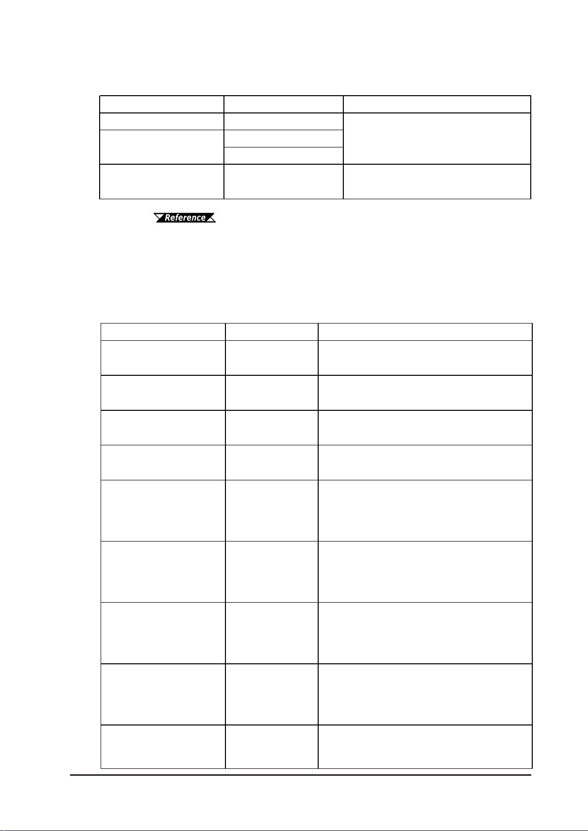
Serial Interfaces (Type C)
Product Name Model No. Description
RS-232C ca b l e
RS-422 ca b le
RS-422 ca b le Connector
Term inal Block Conversi on
Adapter
*1
*1
*1
1 For detailed information about the range of connectable external
Flex Network I/O Units (Type B/Type B+/Type C)
GP410-IS00-0
GP230-IS11-0
GP230-I S12- 0 ( f or Multi-link )
GP070-CN10-0
Int er f ace cable between the external device and
the LT.
Conversion adapter conv er ts serial data to the RS422 for mat.
devices, refer to the LT Editor Device Connection Manual (included
with the LT Editor software) and the GP-PRO/PBIII Device/PLC
Connection Manual (included with the C-Package software).
Product Name Model No. Description
Flex Network 16- P oint Input
Sink Source Type I/O Unit
Flex Network 32- P oint Input
Sink Source Type I/O Unit
Flex Netw ork 16-Point Output
Sink Ty pe I/O Unit
Flex Netw ork 16-Point Output
Sourc e Ty pe I/O Unit
Flex Network 8-P oint Input
Sink Source / 8-Point
Transis t or Out put Sink Type
I/ O U nit
Flex Network 16- P oint Input
Sink Source / 16 - Point
Transis t or Out put Sink Type
I/ O U nit
Flex Network 16- P oint Input
Sink Source/16-Point
Transis t or Out put Sink Type
I/ O U nit
FN-X16T S41
FN-X32T S41
FN-Y16SK41 16-point output sink I/O Unit.
FN-Y16SC41 16-point output source I/ O Unit .
FN-XY08TS41
FN-XY16SK41
FN-XY16SC41
16-point s ink/source shared I/O Unit . DC24V input signal
can be connected.
32-point s ink- s ource shared I /O Unit. DC24V input signal
can be connected.
8-point input sink-source and 8-point t r ansis t or out put sink
mixed I/O unit . Both DC24V input signals and DC24V
output ( load current: 200mA max. ) devices can be
connected.
16-point input sink-source and 16-point t r ans ist or out put
sink mixed I/ O unit . B ot h DC24V input signals and DC24V
output ( load current: 200mA max. / 1. 6A/common) dev ices
can be connected.
16-point input sink-source and 16-point t r ans ist or out put
source mixed I/O unit . B ot h DC24V input signals and
DC24V output (load current: 200mA max./ 1.6A/ common)
dev ices can be connected.
Flex Network 32- P oint Input
Sink Source / 32 - Point
Transis t or Out put Sink Type
I/ O U nit
Flex Netw ork 8-Point Relay
Output / 1 Common Ty pe I/O
Unit
FN-XY32SKS41
FN-Y08RL41
32-point input sink-source and 32-point t r ans ist or out put
sink mixed I/ O unit . B ot h DC24V input signals and DC24V
output ( load current: 200mA max. / 1. 6A/common) dev ices
can be connected.
8-point r elay output ( 1 common)I/O Unit. Up to AC240V (1A)
load current can be connected.
LT Series User Manual 1–9
Page 29

Chapter 1 – Introduction
Flex Network
Single-Ax is Motor Driver
Connects the Flex Net wor k single- axis positioning unit and
Installation Fastener
s
Single Ax is Teaching Loader
Connects the S ingle- Axis Positioning unit to the S ingle-
DIO Conne c t or
Connectors (terminal screws) for " FN-X Y32SKS41", "FN-
Flex Netw ork 2-Channel
Conv er t s 2- channnel analog signals to digit al s ignals at
Flex Netw ork 2-Channel
Conv er t s 2channel 12-bit digit al s ignal t o analog signal
Flex Netw ork 4-Channel
Conv er t s 4- channnel analog signals to digit al s ignals at
Flex Netw ork 4-Channel
Conv er t s 4- channel 12-bit digit al signal to analog signal
Analog Units
Product Name Model No. Description
Analog/Digital Conv e r s ion
Digita l/Analog Conve rs ion
Analog/Digital Conv e r s ion
Digita l/Analog Conve rs ion
Positioning Units
Product Name Model No. Description
Single-Axis Positioning Unit
Flex Network
Teaching Loader for SingleAxis Posit ioning Unit
High-Speed Counter Unit
Product Name Model No. Description
Flex Network
High Spe e d Counter Unit
FN-AD02AH41
FN-DA02AH41
FN-AD04AH11
FN-DA04AH11
FN-PC10SK41
FN-PC10LD41
FN-HC10SK41
12-bit r es olut ion.
and sends output.
12-bit r es olut ion.
and sends output.
Both of this unit and GLC/LT can store positioni ng data. Motor
driver connection cable(FN-PC10CB01) is required.
Programmer for Single-Axis Positioning Uni t. Allows entry, editing
and operation checking of high-precision positioning data
(5m cable included)
High performance High-Speed counter that can easily
change counter input t ypes. Can create bot h a wide range
of dat a and cam output.
Optional Items
Item M ode l No. Description
Screen Protection Sheet
(5 sheet s / s et )
Connec t ion C a ble
Optional Maintenance Items
GP37W2-DF00
FN-PC10CB01 (1m)
The following items are included in the L T unit’s packing box, and are also sold separately .
Product Name Model No. Description
(4 fas t ener s / s et )
Installation Gasket GP37W2-WP00-MS
Flex Network
Comm unic a t ion C a ble
Connector
GP070-AT01 Fasteners to attach the LT to a panel.
FN-IFCN01
Disposable protective and dirt-res istant sheet for the LT
unit' s s creen. The LT unit's t ouch panel can be used with
this cov er s heet attached.
the ser vo and stepping dr ivers.
Provides a moisture- res is t ant s eal when ins t alling t he LT.
Same as the seal included in the LT unit's or iginal
equipment package.
Connector is at t ached to t he Flex Net wor k I / F unit . E nable
the connection of t he Flex Network Communication
Cable.
Cable
(S pr ing Type )
FN-LD10CBL (5m)
GLC-DIOCN03
A x is Teaching Loader.
XY32SCS41" unit s . E as y-to-us e s pring- clamp ty pe.
LT Series User Manual1–10
Page 30
1. General Specifications
2. Functional Specifications
3. Interface Specifications
Chapter
2 Specifications
2.1 General Specifications
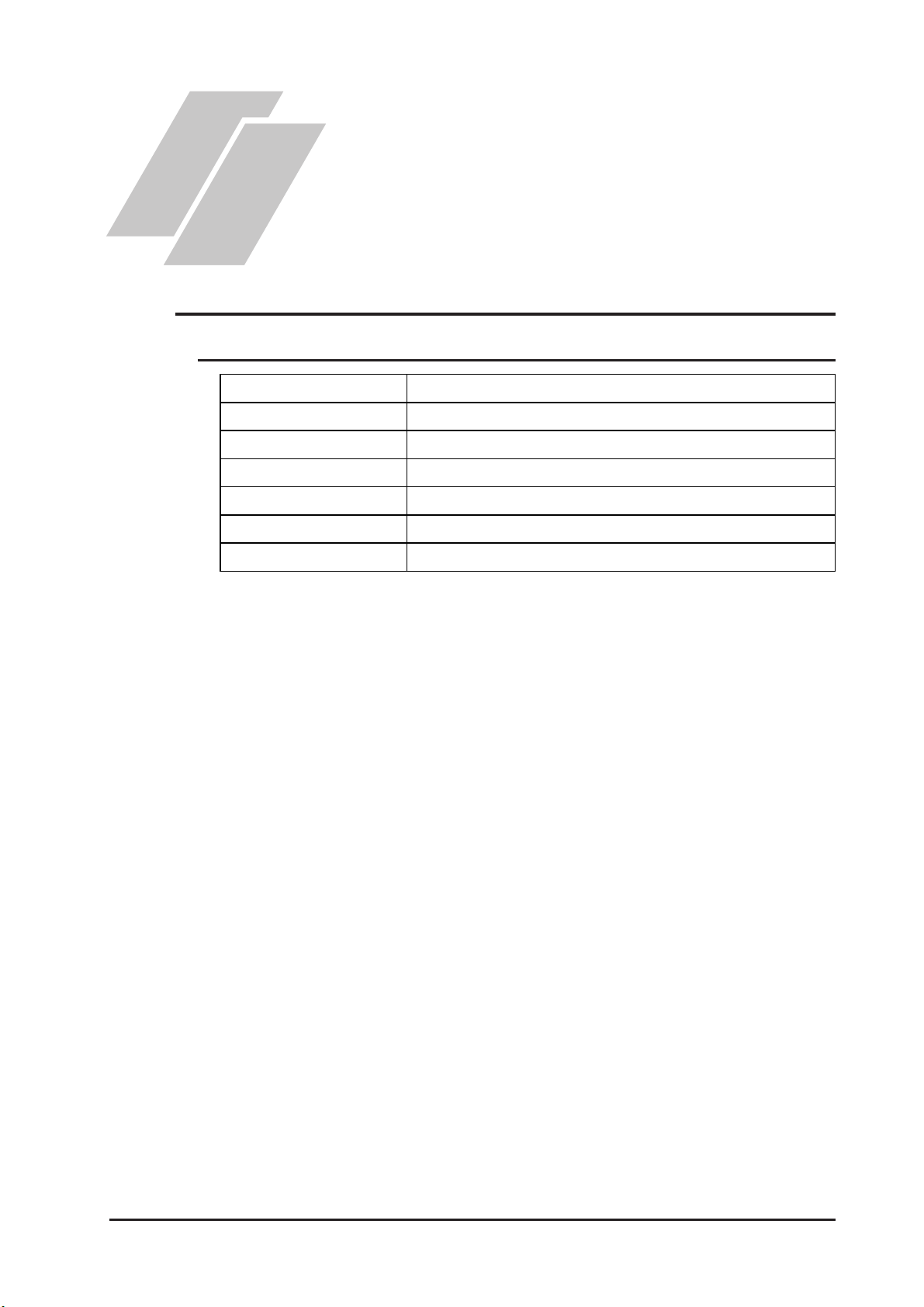
2.1.1 Electrical
4. Part Names and Functions
5. Dimensions
Rated Voltage
Voltage Supply Range
Allowable Voltage Drop
Power Consumption
In-Rush Current
Voltage Endurance
Insula tion Resista nce
DC 24V
DC 20.4V to DC 28.8V
10 ms or less
20 W or less
30 A or less
A C 1000V at 10 mA for 1 minute (between VCC and FG terminals)
DC 500V at 20 MΩ or higher (between V CC and FG terminals)
2–1LT Series User Manual
Page 31
Chapter 2 – Specifications
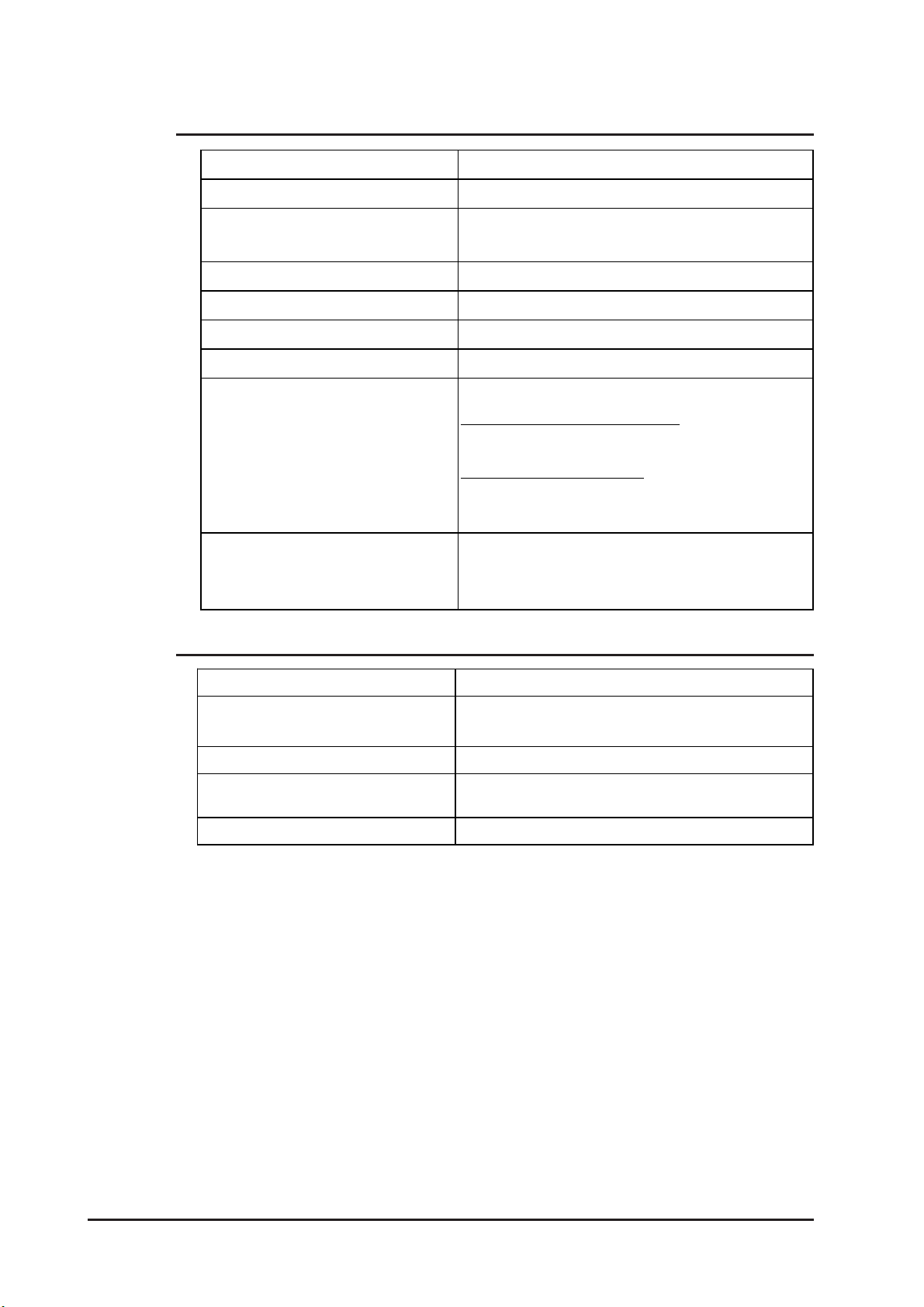
2.1.2 Environmental
Ambient Operating Temperature
Storage Temperature
Ambie nt Humidity
Atmosphere
Air P u r ity (Dust)
Corrosive Ga sse s
Atmospheric Pr e ssure
Vibra tion Re sistance
Noise Immunity
(via noise simulator)
0o C to +50o C
-20o C to +60o C
10% RH to 90% RH ( no condensation,
wet bulb temperature: 39
o
C max.)
Pollut ion Degree 2
0.1 mg/m3 or less (non-conductive levels)
Free of corros ive gases
800 hPa to 1114 hPa ( 2000 meters or lower)
IEC61131-2 (JIS B 3501) compliant
Whe n vibrat ion is NOT continuous
10 Hz to 57 Hz 0. 075mm, 57 Hz t o 150 Hz 9.8 m/s
When vibration is continuous
10 Hz to 57 Hz 0. 035mm, 57 Hz t o 150 Hz 4.9 m/s
X, Y, Z directions for 10 times (80 min.)
Noise Voltage: 1500 V
p-p
Pulse Dur at ion: 1 µs
Rise Time: 1 ns
2
2
2.1.3 Structural
Grounding
Ratings
External Dim ensions
Weight
Cooling Method
*2
100Ω or less , or your countr y's applicable st andar d
Equivalent to IP65F (JEM 1030), NE MA #250
TYPE 4X/12
W207 x H157 x D75.8 mm [W 8.15 x H6.18 x D2.98 in.]
1.5 k g ( 3.3 lb) or less
Natural air circulation
1 Grounding requirements differ from country to country. Confirm the requirements of
your work environment prior to installation. For further information, please contact
your Pro-face distributor.
2 The front face of the LT unit is installed in a solid panel, and has been tested under
conditions equivalent to the standards listed in the specifications. The LT unit’s level of
resistance is equivalent to these standards; however, oils that should have no effect on
the LT can harm the unit — when vaporized oils are present, when low-viscosity cutting
oils are allowed to adhere to the unit for long periods of time, or if the protective sheet
on the front face of the LT peels off. These conditions can lead to the ingress of oil into
the LT, and alternate protective measures are recommended. Also, the presence of nonapproved oils may cause deformation or corrosion of the front panel’s plastic cover.
Therefore, prior to installing the LT, confirm the type of conditions that will be present in
the LT unit’s operating environment. If the installation gasket is used for a long period of
time, or if the unit and its gasket are removed from the panel, the original level of the
protection cannot be guaranteed. To maintain the original protection level, replace the
installation gasket regularly.
*1
LT Series User Manual2–2
Page 32
Chapter 2 – Specifications
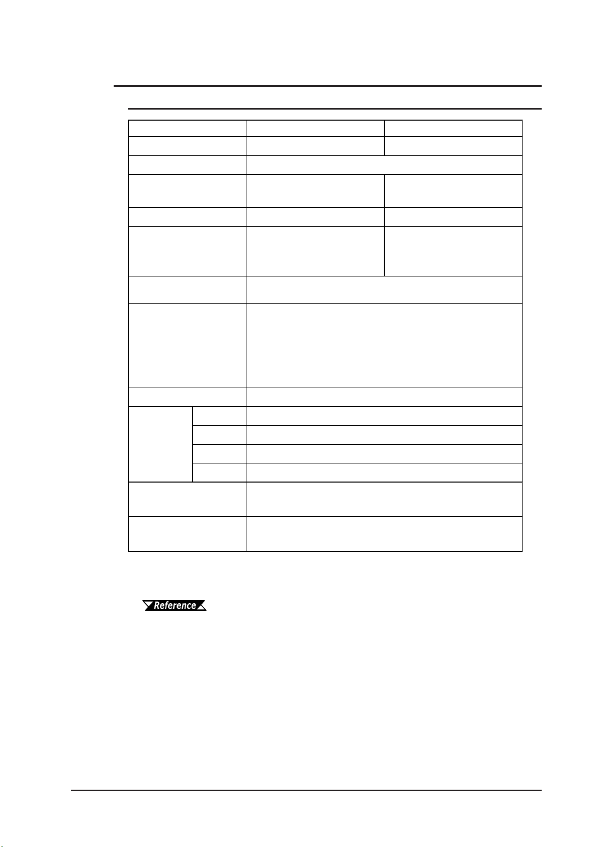
2.2 Functional Specifications
2.2.1 Display
GLC150-BG41-******-24V GLC150-SC41-******-24V
Type
Resolution
Effective Display Area
Colors
Backlight
Contrast Adjustment
Control
Language Fonts
Touch Panel
8x8 dot s
8x16 dots
Text
16x16 dot s
Monochrome LCD
STN Color LCD
320x240 pix els
W115. 2 x H86. 4 mm
[W4.54 x H3.40 in.]
Blue mode (monochrome)
CFL (lifes pan: more t han 25,000
hours when continuously lit)
W118. 2 x H89. 4 mm
[W4.65 x H3.52 in.]
64 colors
CFL (lifes pan: more t han 36,000
hours when continuously lit)
8 levels of adjust ment available v ia t o uch panel.
ASCII: (Code page 850) Alphanumeric (incl. Eur. characters)
China: (GB2321 – 80 codes) simplified Chinese font s
Japan: ANK158, Kanji: 69 62 (J I S S t and ards 1& 2)
Korea: (KSC5601 – 1992 codes) Hang ul f ont s
Taiwan: (B ig 5 codes) t r adit ional Chines e f ont s
16x12 grid of touch panel key s ( 1 or 2 po int t ouch)
40 Char. x 30 r ows
40 Char. x 15 r ows
20 Char. x 15 r ows
32x32 dot s
Display S izes
Font Sizes
1 The display font will differ depending on which (language) character, or which size you
select.
*1
10 Char. x 7 r ows
8X8 dot f ont, 8X16 dot f ont, 16X16 dot font, and 32X 32 dot font
Bot h height an d widt h can be expanded 1, 2, 4, or 8 times.
Section 6.9 – “Font Setting”
LT Series User Manual 2–3
Page 33
Chapter 2 – Specifications
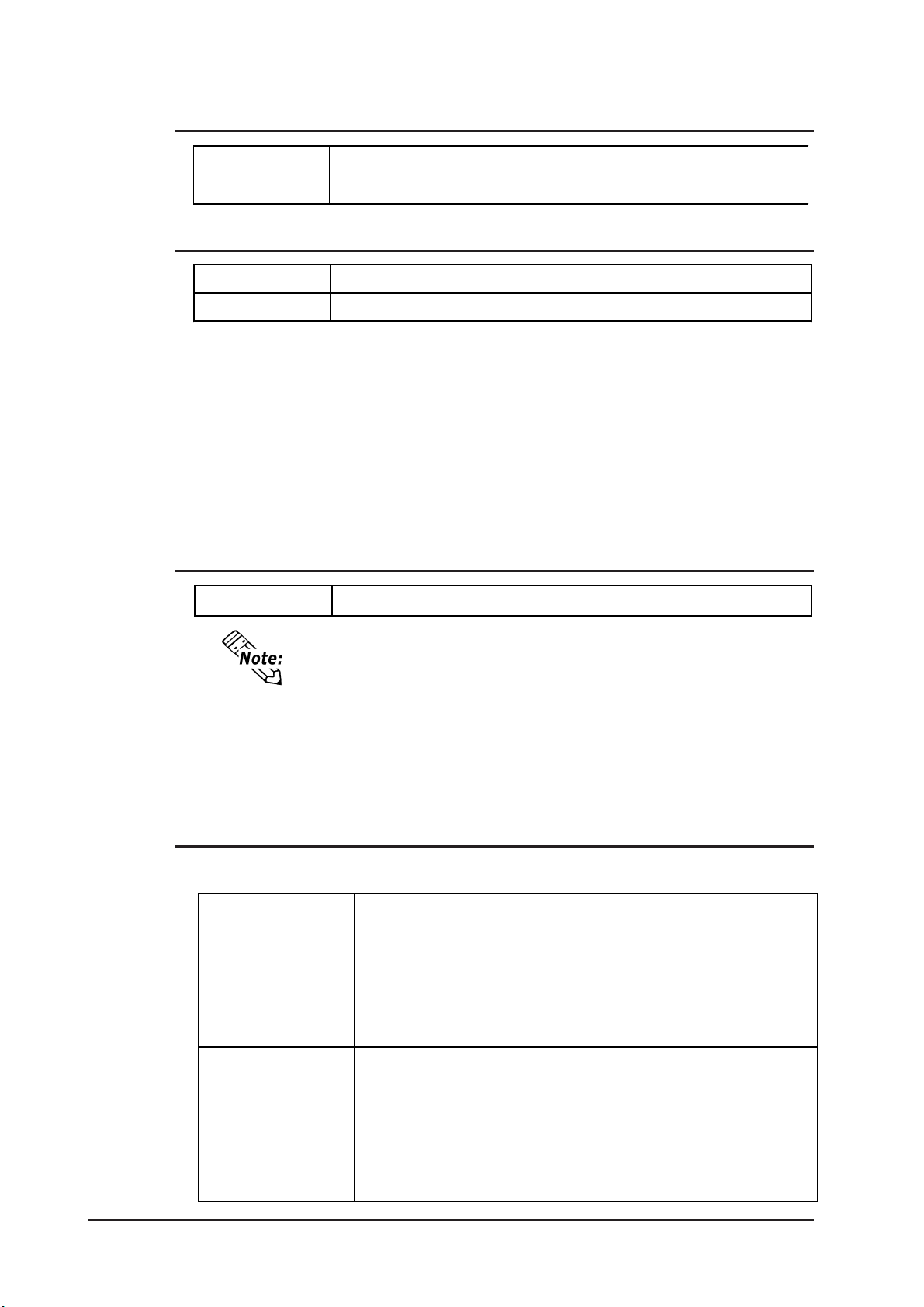
2.2.2 Memory
Application
Da t a B ac kup
1 MB FLA S H E PR OM (A p prox . 32 0 screens at 3.2 KB/screen)
96 KB SRA M (uses lithium battery )
*1
2.2.3 Control Memory
Variable Area
Program Area
32 KB SRAM (uses lithium battery)
128 KB FLASH EPROM
1 A Lithium battery’s lifetime is:
• 10 years when the battery’s ambient temperature is under 40
• 4.1 years when the battery’s ambient temperature is under 50
• 1.5 years when the battery’s ambient temperature is under 60
When used for backup - assuming 96 hours (4 days) to charge fully:
• Approximately 60 days with a fully-charged battery
• Approximately 6 days with a half-charged battery
*1
2.2.4 Clock
Clo ck Accu ra cy
±65 seconds/mont h (at r oom temperature)
o
C
o
C
o
C
The LT unit’s internal clock has a slight degree of error in
accuracy. At normal operating temperatures and conditions,
and with the LT operating from its lithium battery, the degree
of error is ±65 seconds per month. Variations in operating
conditions and battery life can cause this error to vary from 380 to +90 seconds per month. For systems where this degree of error will be a problem, the user should monitor this
error and make adjustments as required.
2.2.5 External Interfaces
Serial Interface for Type C and Tool Connector (All Types)
Asy nchronous Transmission:
RS-232C or RS- 422
Serial Interface
Tool Connector
Data Lengt h: 7 or 8 bit s
St op B it : 1 or 2 bit s
Parity: None, Odd, or Even
Data Transmission Speed: 2400 bps t o 115. 2 k bps
Asy nchronous TTL level nonprocedural command I/ F
During Screen File (HMI int er face) Development:
• used to transf e r data between th e LT application sof t war e/
C-Package and t he LT unit
During Operation:
• used f or a variety of devices, including a bar-code reader
LT Series User Manual2–4
Page 34
Chapter 2 – Specifications
Flex Network Interface (Type B/Type B+/Type C)
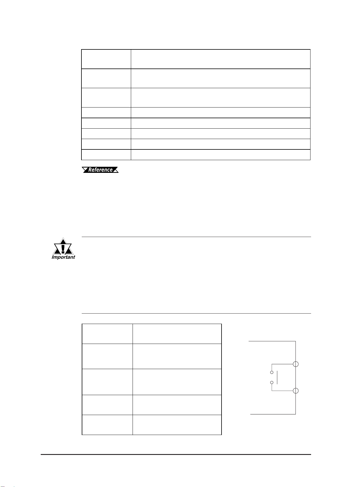
Communication
Type
Connection
Method
1:N
Mult i D r o p
A t 6 Mbps: 200 m per CH
Transfer Distance
Transfer Method
Transfer Speed
Transfer I/F
Error Check
No. of Stations
A t 12 Mbps: 100 m per CH
During cy clic period, distributed transmission, Half-duplex
6 Mbps (for 100 m), 12 Mbps (for 200 m)
Differential method, Pulse transfer resistance
Format check, bit check, CRC-12 check
63 (max.), 1008 I/O points (depending on ty pe of units used.)
For detailed information, refer to the Flex Network User Manual.
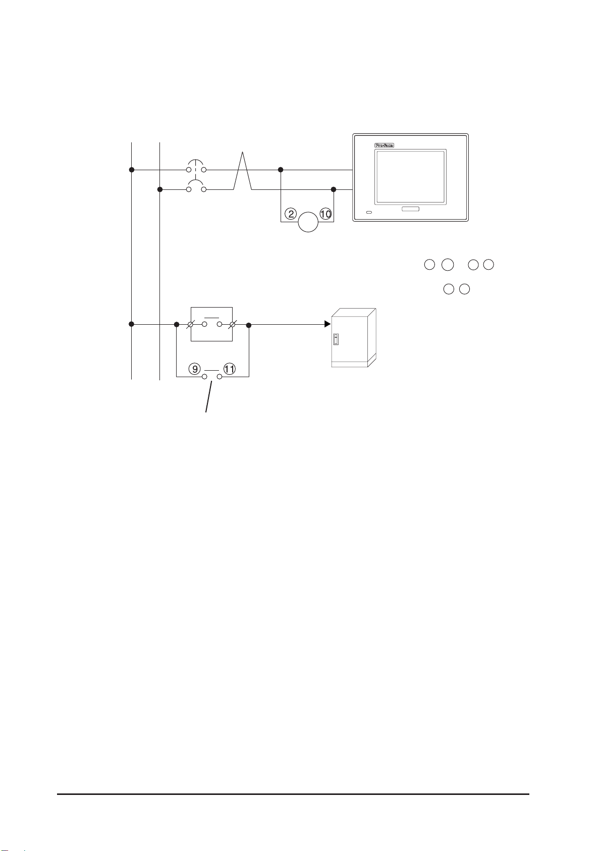
Alarm Output for Circuit (All Types)
Turning the LT unit ON will start the unit’s system software and the alarm output
circuit’s relay. When a major error triggers a watchdogtimer alarm, however, this
relay will turn OFF. Since an undefined LT input or output condition can occur, be
sure to design an external failsafe circuit that will monitor the output of this relay.
• When the LT unit’s power is turned ON, the Alarm Output is turned OFF
for approximately 1 second. Therefore, be sure to design your circuits
so that they disregard a 1 second Alarm Output stop after the LT unit’s
power is turned ON.
Example: Insert an external timer in series with the Alarm Output that
turns OFF 1.5 seconds after power is turned ON.
For circuit design examples,
LT Series User Manual 2.2.5 External Inter-
face Alarm Output
Contact Rating
Opera ting Ti m e
(Set Time at
o
C)
20
Recovery Hours
(Reset Time is
set at 20
Minimum
Sw i tching Loa d
o
C)
0.15A – AC 125V Resist an ce Load
0.6A – DC 24V Res istance Load
4ms or less
4ms or less
1mA / DC 5V
LT
ALARM
Initial Contact
Resistance
100mΩ or less
LT Series User Manual 2–5
Page 35
Chapter 2 – Specifications
OMRON Corporation Timer H3CR-A Circuit Drawing
This Circuit uses a H3CR-A terminal number.
DC24V
LT Alarm Contact
Timer
This turns ON when
power is turned ON,
and after 1 second,
turns OFF.
Timer
LT Alarm
DC24V
Power OFF Delay Timer (1 sec.)
Omron H3CR-A (C-Mode)
Use H3CR-A’s 9 - 11 or 1 - 3 contacts.
(Start signal lines 2 - 6 must be
shorted together.)
LT External Alarm Monitor
Design an LT Alarm Monitor that
monitors the Alarm contact’s OFF
state, after DC24V power is turned
ON.
LT Series User Manual2–6
Page 36
Chapter 2 – Specifications
2.3 Interface Specifications
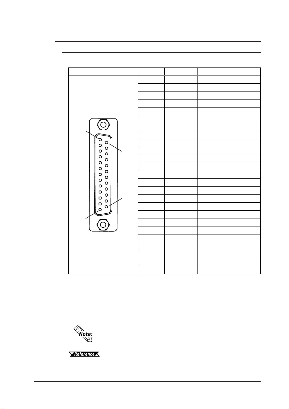
2.3.1 Serial Interface (Type C)
Either the RS-232C or RS-422 interface connects the LT to the external device.
Pin Assignments Pin # Signal Name Condition
1 FG Frame Ground
(D-Sub 25-pin female)
SIO
1
14
25
13
2 SD Send Data (RS-232C)
3 RD Receive Data (RS-232C)
4 RS Request Send (RS-232C)
5 CS Clear Send (RS-232C)
6 NC No Connection
7 SG Signal Ground
8 CD Carrier Detect (RS-232C)
9 TRMX Terminat i on (RS-422)
10 RDA Receive Data A (RS-422)
11 SDA Send Data A (RS-422)
*1
12
*1
13
14 VCC 5V ±5% Output 0.25 A
15 SDB Send Data B (RS-422)
16 RDB Receive Data B (RS-422)
17 NC No Connection
18 CSB Clear Send B (RS-422)
19 ERB Enable Receive B (RS-422)
20 ER Enable Receive (RS-232C)
21 CSA Clear Send A (RS-422)
22 ERA Enable Receive A (RS-422)
23 NC Not Connected
24 NC Not Connected
25 NC Not Connected
RESERVE Reserved
RESERVE Reserved
1 The #12 and #13 pins are RESERVED. Do NOT connect to these pins.
Recommended Parts:
Connector: Dsub25pin plug XM2A-2501 (OMRON Corp.)
Cover: Dsub25pin cover XM2S-2511 (OMRON Corp.)
Jack Screws XM2Z-0071 (OMRON Corp.)
Use rough metric type M2.6x0.45 p threads used to secure
the cable’s set screws.
Cable: CO-MA-VV-SB5PX 28AWG (HITACHI Cable, Ltd.)
To confirm the connection specifications for your external device,
refer to the L T Editor Device Connection Manual (included with the
LT Editor software), the GP-PRO/PBIII Device/PLC Connection
Manual (included with the C-Package software).
LT Series User Manual 2–7
Page 37
Chapter 2 – Specifications
Use the following instructions to create your own cable:
With the RS-422:
• The following pins must be connected in pairs, as follows:
#18 (CSB) <—> #19 (ERB)
#21 (CSA) <—> #22 (ERA)
• When connecting the RS-422 cable’s #9 (TRMX) and
#10 (RDA) pins, a termination resistance of 100 Ω is added
between the #10 (RDA) and #16 (RDB) pins.
• When making a cable for a Memory Link system, use a 4wire type of cable.
With the RS-232C:
• Do NOT use the following pins:
#9 (TRMX) #10 (RDA) #11 (SDA)
#15 (SDB) #16 (RDB) #18 (CSB)
#19 (ERB) #21 (CSA) #22 (ERA)
Connect the #1 (FG) terminal only if it is required by a connected device.
• This L T unit’s serial port is not isolated. To reduce the risk of damage to
the RS-422 circuit, it is important that you connect the SG/GND (Signal
Ground) terminals.
• FG and SG terminals are internally connected in the LT. When connecting to another device, be sure to not create an SG shorting loop in your
system.
• Pin #14 (VCC) DC 5V Output is not protected. T o prevent damage or unit
malfunction, use only the designated level of current.
LT Series User Manual2–8
Page 38
Chapter 2 – Specifications
2.3.2 Flex Network Interface (Type B/Type B+/Type C)
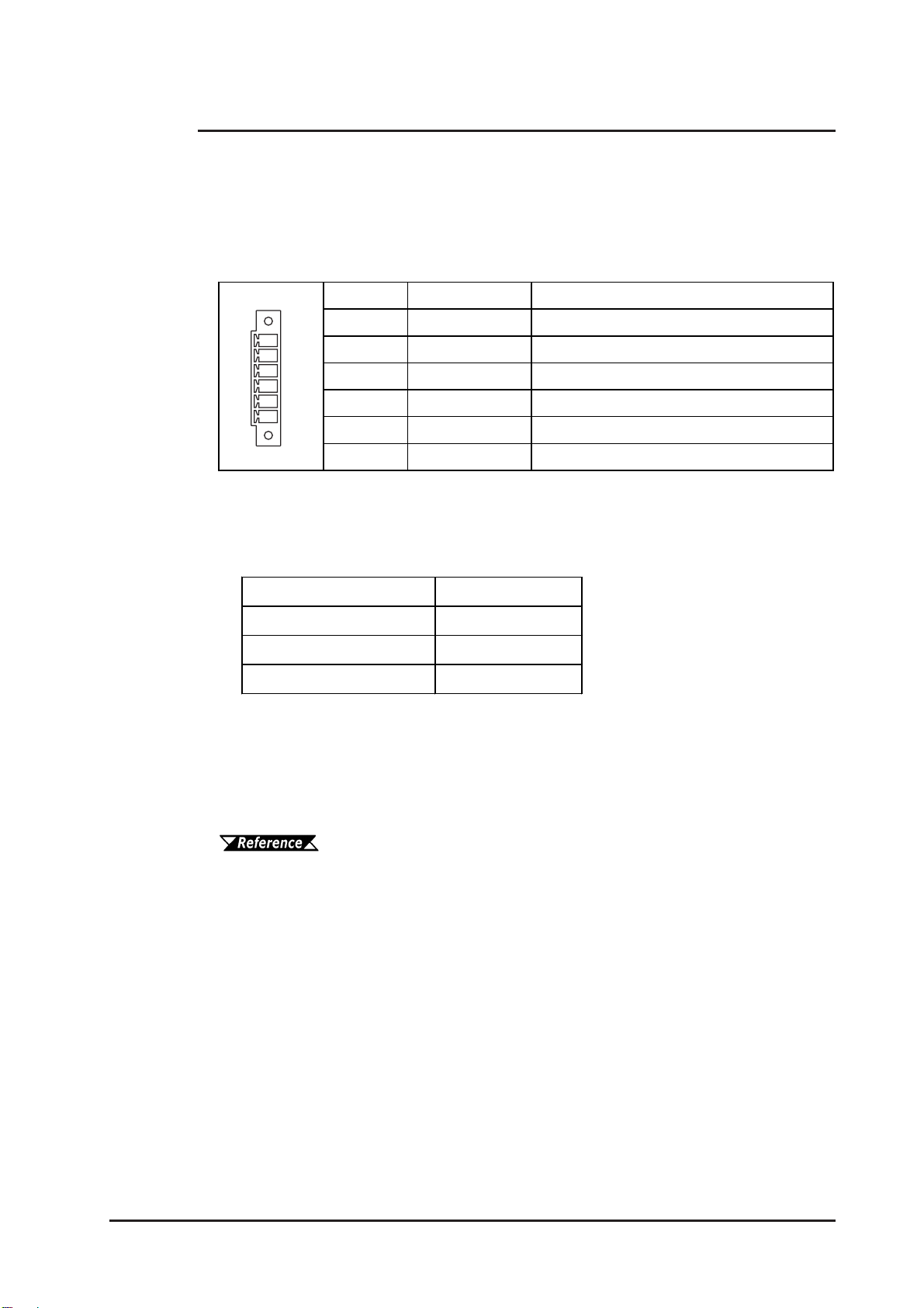
The following table specifies the signals of the Flex Network I/F Connector
(included with the LT unit). Use these specifications to connect the LT to the Flex
Network I/O unit using the Network Communication Connector included in the
LT unit’s packing box.
Flex Network I/F Connector
Pin # Signa l Na m e Condition
6 SLD CH 2 Shield Line (SLD)
6
5
4
3
2
1
Flex Network Communication Cable
5 TR- CH 2 Communication Data (TR-)
4 TR+ CH 2 Communicati on Data (TR+)
3 SLD CH 1 Shield Line (SLD)
2 TR- CH 1 Communication Data (TR-)
1 TR+ CH 1 Communicati on Data (TR+)
Use the following Flex Network Communication Cable when connecting to the
Flex Network Unit.
Model Length pe r Unit
FN-CABLE2010-31 -MS 10 m
FN-CABLE2050-31 -MS 50 m
FN-CABLE2200-31 -MS 200 m
Flex Network Communication Connector
The Flex Network Communication Connector is included with the LT unit, and is
also available as an optional maintenance item, such as FN-IFC01.
Section 1.3 – “Accessories”
For detailed information about the Flex Network, refer to the Flex
Network User Manual.
LT Series User Manual 2–9
Page 39
Chapter 2 – Specifications
2.3.3 Input/Output Connector Interface (Type A1/Type A2/Type B+)
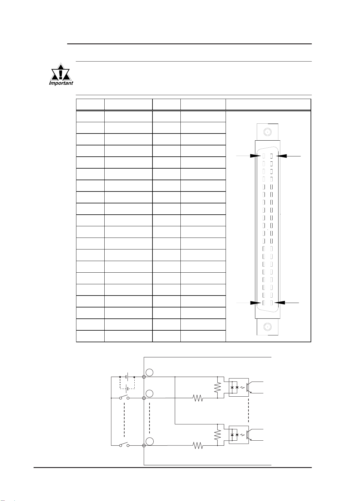
Input/Output Connector (Type A1)
This connection drawing is as seen from the LT. The cable connector will
use the A, B marks to show pin orientation. Be sure to check this orientation prior to creating your cable.
Pin Signal Name Pin Signal Name LT Connector
A1 COM (0V:DOUT) B1 COM(24V:DIN)
A 2 COM (0V :DOUT) B2 DC 24V (DOUT)
A 3 NC B3 NC
A 4 NC B4 NC
A 5 DOUT15 B5 DIN15
A 6 DOUT14 B6 DIN14
A 7 DOUT13 B7 DIN13
A 8 DOUT12 B8 DIN12
A 9 DOUT11 B9 DIN11
A10DOUT10B10 DIN10
A11 DOUT9 B11 DIN9
A12 DOUT8 B12 DIN8
A13 DOUT7 B13 DIN7
A14 DOUT6 B14 DIN6
A15 DOUT5 B15 DIN5
A16 DOUT4 B16 DIN4
A17 DOUT3 B17 DIN3
A18 DOUT2 B18 DIN2
A1 B1
B20A20
A19 DOUT1 B19 DIN1
A20 DOUT0 B20 DIN0
♦ Input Circuit (Type A1)
DC24V External
Power Supply
- +
+ -
*
COM
IN
IN
B1
B5
B20
* Dotted line shows connection to source output type
Internal Circuit
Internal Circuit
LT Series User Manual2–10
Page 40
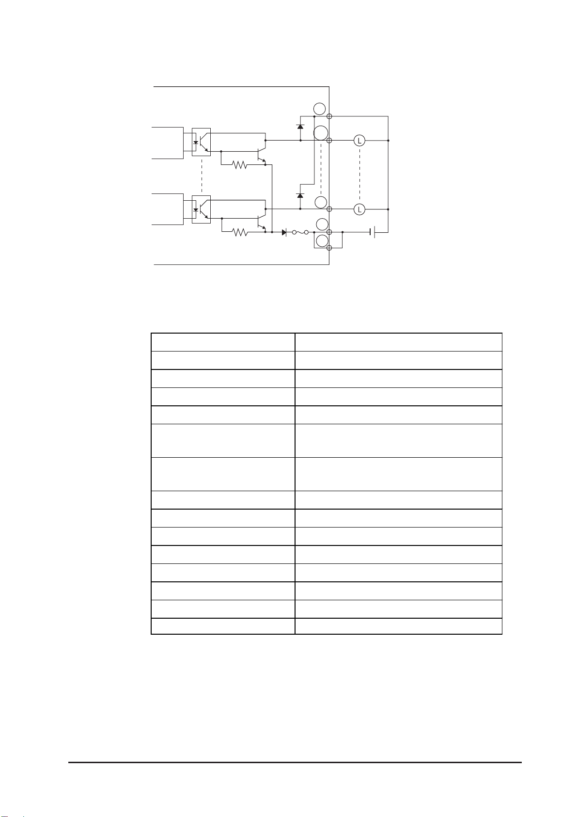
♦ Output Circuit (Type A1)
Internal Circuit
Internal Circuit
♦ Input Specifications (Type A1)
3.5 A
Quick
Break Fuse
Chapter 2 – Specifications
B2
+24V
A5
OUT
A20
OUT
- +
A1
A2
COM
DC 24V
External
Power Supply
Ra ted Vo l tage
Maximum Allowable Voltage
Input Method
Ra ted Cu r r en t
Input Resistance
Opera tion Ra nge
Input Dela y Tim e
Common Lines
Common Lines Al l oca tion
Externa l Conne ction
Input Points
Input Signa l Display
Status Display
Isola tion Method
DC 24V
DC 26.4V
Source/Sink Input
5 mA ( 24V)
4.7 k
Ω
ON V o lt age: 21V or more
OFF Voltage: 7V or less
OFF to ON: 10 ms or less
ON to OFF: 10 ms or less
1
16 points/1 common line
40-pin connector (used with Output section)
16
LED light s w hen each point turns ON (logical side)
None
Photocoupler Isolat ion
Externa l P ower Supply
For Signal: DC 24V
LT Series User Manual 2–11
Page 41
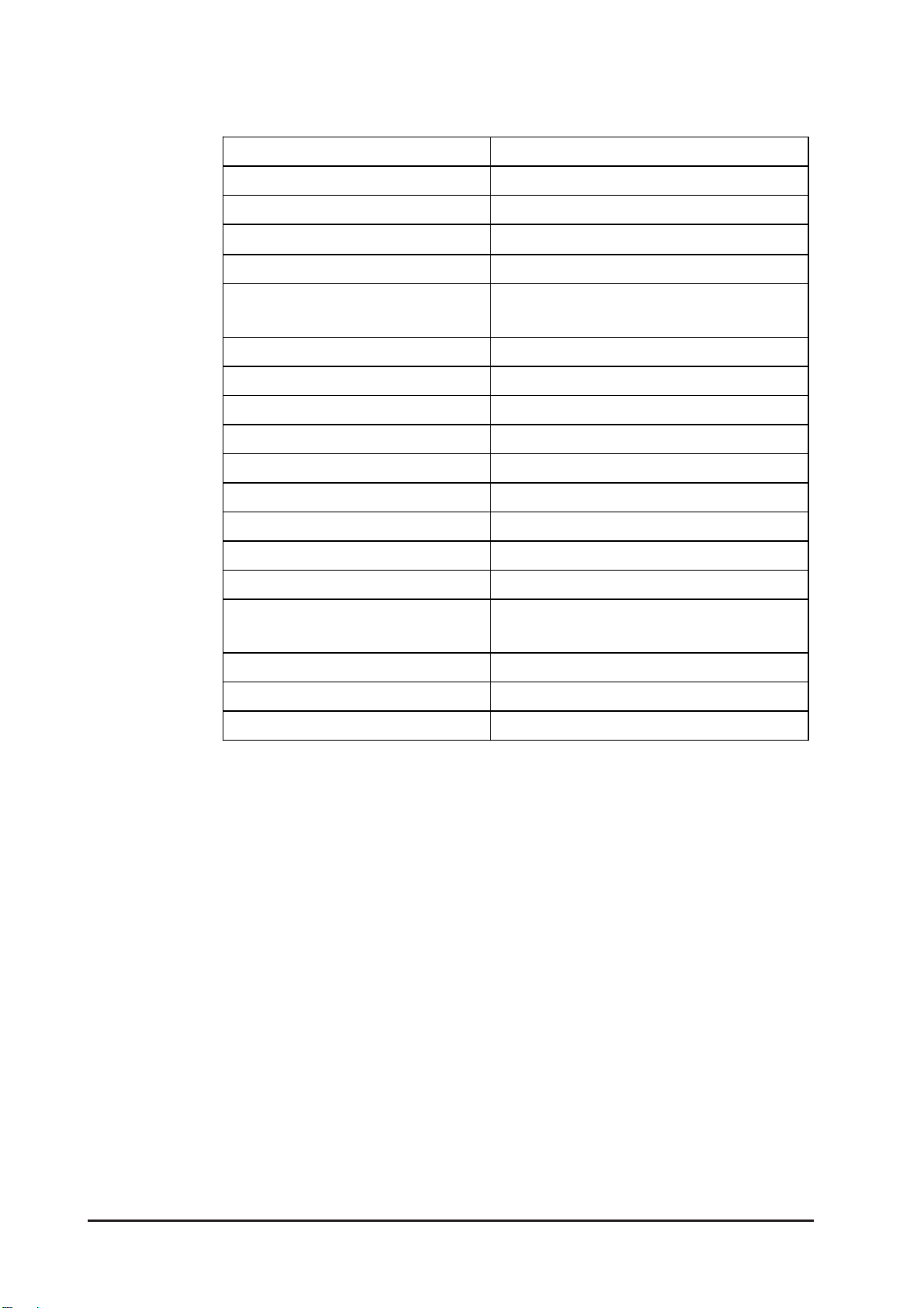
Chapter 2 – Specifications
♦ Output Specifications (Type A1)
Ra ted V o ltag e
Rated Vol ta ge Range
Output Method
Maxi m um Load Volta ge
Output Volta ge Drop
Output Delay Time
Voltage Leakage (when OFF)
Type of Output
Common Lines
Common Design
Externa l Connection
Output Protection Type
Internal Fuse
Surge Control Ci rcui t
Output Points
DC 24V
DC 24V ±10%
Sink Output
0.2 A/point 1. 6 A/common
2.5V or less
OFF to ON: 2 ms or less
ON to OFF: 2 ms or less
0.4 mA or less
Transistor Output
1
16 points/1 common line
40-pin connector (also us ed for Input )
Output is unprot ected
3.5 A , 125 V Chip Fuse (non-r eplaceable)
Diode
16
Output Signal Display
Status Display
Isola tion Method
Externa l Power Suppl y
LED lights when each point turns ON
(logical side)
None
Photocoupler Isolat ion
DC 24V
LT Series User Manual2–12
Page 42
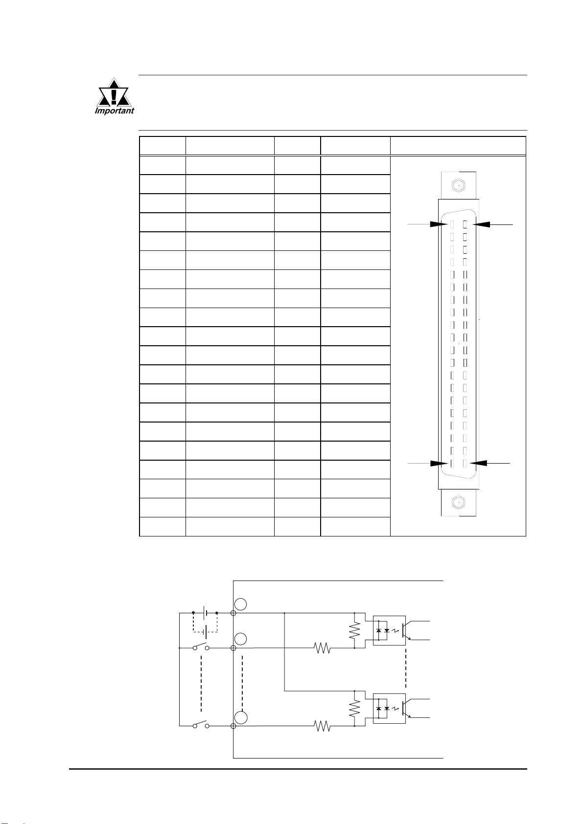
Chapter 2 – Specifications
Input/Output Connector (Type A2)
This connection drawing is as seen from the LT. The cable connector will
use the A, B marks to show pin orientation. Be sure to check this orientation prior to creating your cable.
Pin Signal Name Pin Signal Name LT Connector
A 1 COM (24V:DOUT) B1 COM (0V:DIN)
A 2 CO M (24V :D OUT) B2 0V (D OUT)
A 3 NC B3 NC
A 4 NC B4 NC
A 5 DOUT15 B5 DIN15
A 6 DOUT14 B6 DIN14
A 7 DOUT13 B7 DIN13
A 8 DOUT12 B8 DIN12
A 9 DOUT11 B9 DIN11
A10DOUT10B10DIN10
A11 DOUT9 B11 DIN9
A12 DOUT8 B12 DIN8
A13 DOUT7 B13 DIN7
A14 DOUT6 B14 DIN6
A15 DOUT5 B15 DIN5
A16 DOUT4 B16 DIN4
A17 DOUT3 B17 DIN3
B1A1
B20A20
A18 DOUT2 B18 DIN2
A19 DOUT1 B19 DIN1
A20 DOUT0 B20 DIN0
♦ Input Circuit (Type A2)
DC24V External
Power Supply
+ -
- +
*
COM
IN
IN
B1
B5
B20
* Dotted line shows connection to sink output type
Internal Circuit
Internal Circuit
LT Series User Manual 2–13
Page 43
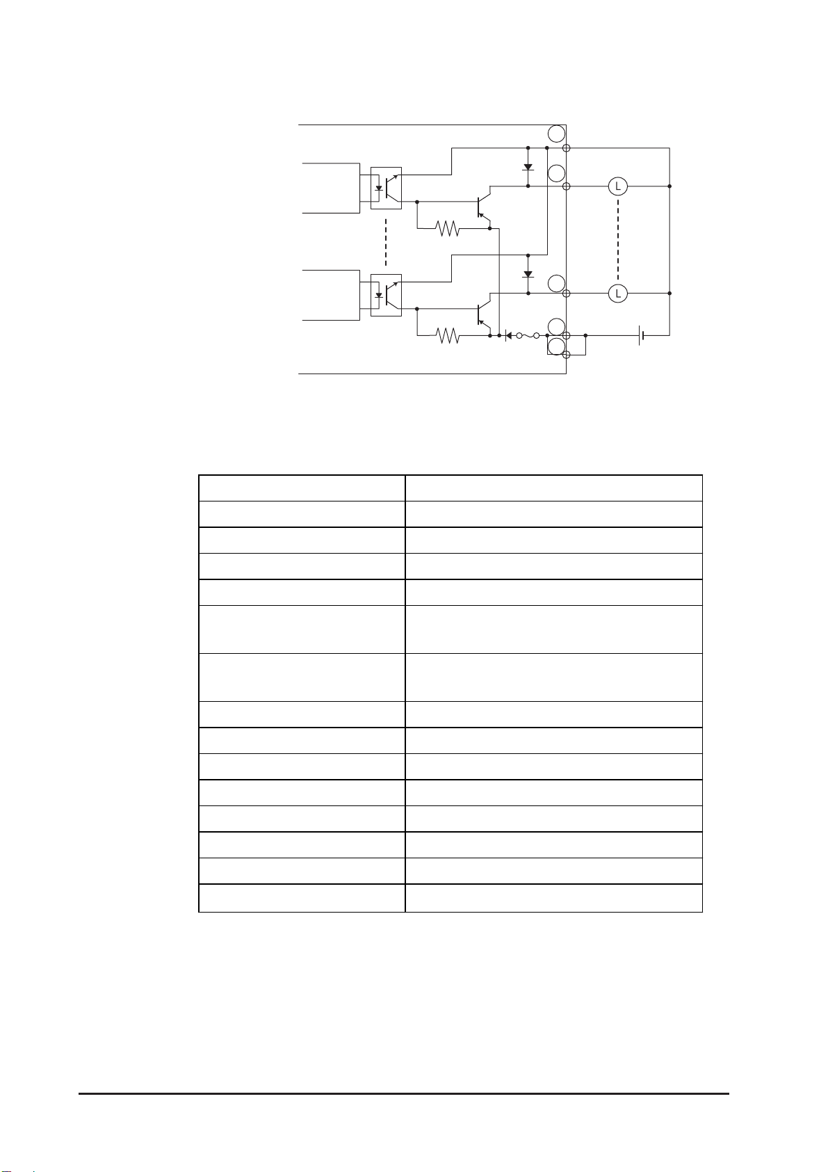
Chapter 2 – Specifications
♦ Output Circuit (Type A2)
Internal Circuit
Internal Circuit
B2
A5
A20
0V
OUT
OUT
♦ Input Specifications (Type A2)
Ra ted Vo l tage
Maximum Allowable Voltage
Input Method
Ra ted Cu r r en t
Input Resistance
Opera tion Ra nge
Input Dela y Tim e
Common Lines
DC 24V
DC 26.4V
Source/Sink Input
5 mA ( 24V)
4.7 k
ON V o lt age: 21V or more
OFF Voltage: 7V or less
OFF to ON: 10 ms or less
ON to OFF: 10 ms or less
1
Ω
3.5 A
Quick
Break Fuse
A1
A2
COM
+ -
DC 24V
External
Power
Supply
Common Lines Al l oca tion
Externa l Conne ction
Input Points
Input Signa l Display
Status Display
Isola tion Method
Externa l P ower Supply
16 points/1 common line
40-pin connector (used with Output section)
16
LED light s w hen each point turns ON (logical side)
None
Photocoupler Isolat ion
For Signal: DC 24V
LT Series User Manual2–14
Page 44
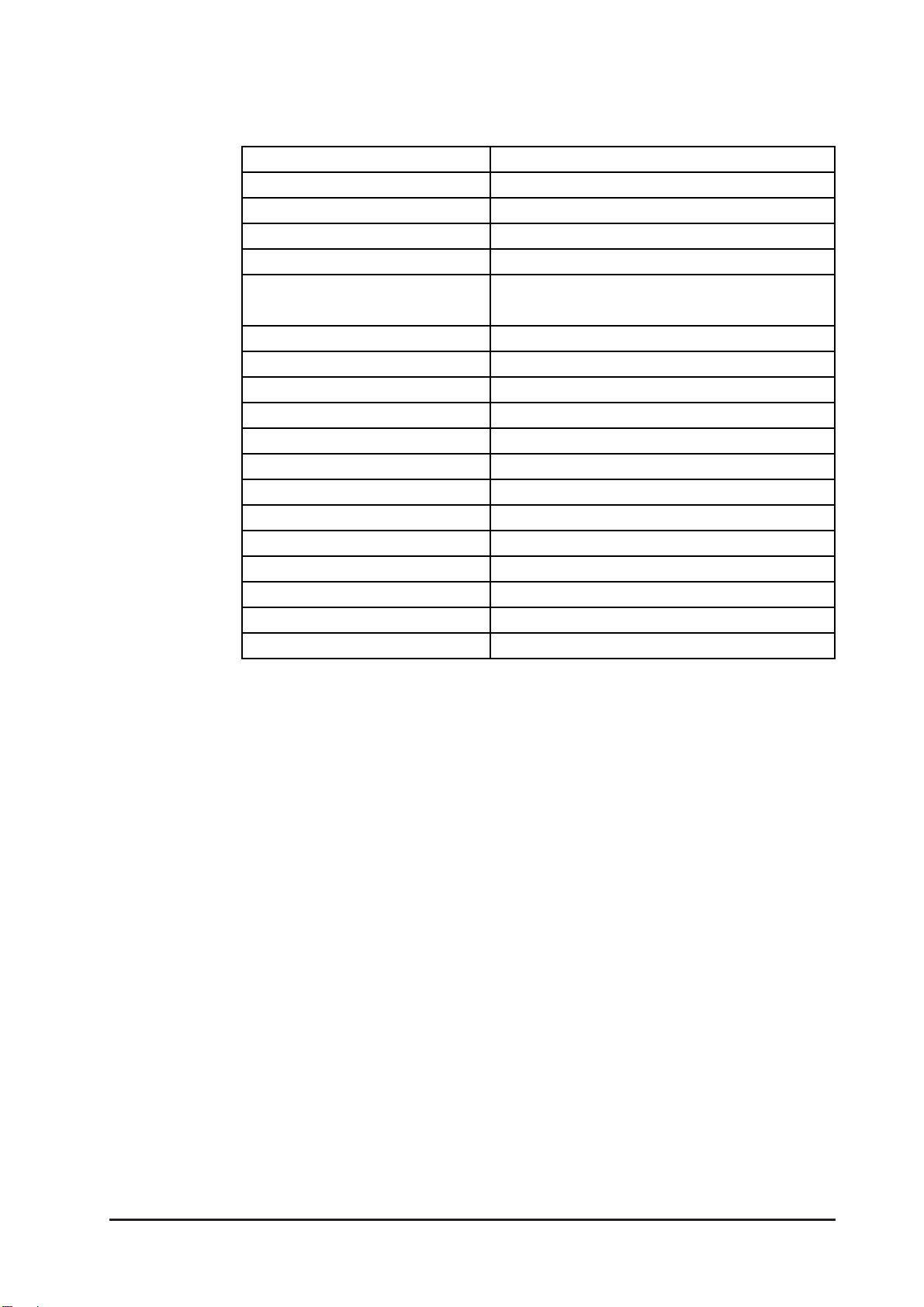
♦ Output Specifications (Type A2)
Chapter 2 – Specifications
Ra ted Vo l tage
Rated Vol ta ge Range
Output Method
Maxi m um Loa d V ol ta ge
Output Volta ge Drop
Output Delay Time
Voltage Leakage (when OFF)
Type of Output
Common Lines
Common Design
Externa l Conne ction
Output Protection Type
Internal Fuse
Surge Control Ci rcui t
Output Points
Output Signal Display
Status Display
Isola tion Method
Externa l P ower Supply
DC 24V
DC 24V ±10%
Source Output
0.2 A/point 1.6 A/common
2.5V or less
OFF to ON: 2 ms or less
ON to OFF: 2 ms or less
0.4 mA or less
Transistor Output
1
16 points/1 common line
40-pin connector (als o us ed for Input )
Output is unprot ected
3.5 A, 125 V Chip Fuse (non-replaceable)
Diode
16
LED lights when each point turns ON (logical side)
None
Photocoupler Isolat ion
DC 24V
LT Series User Manual 2–15
Page 45
Chapter 2 – Specifications
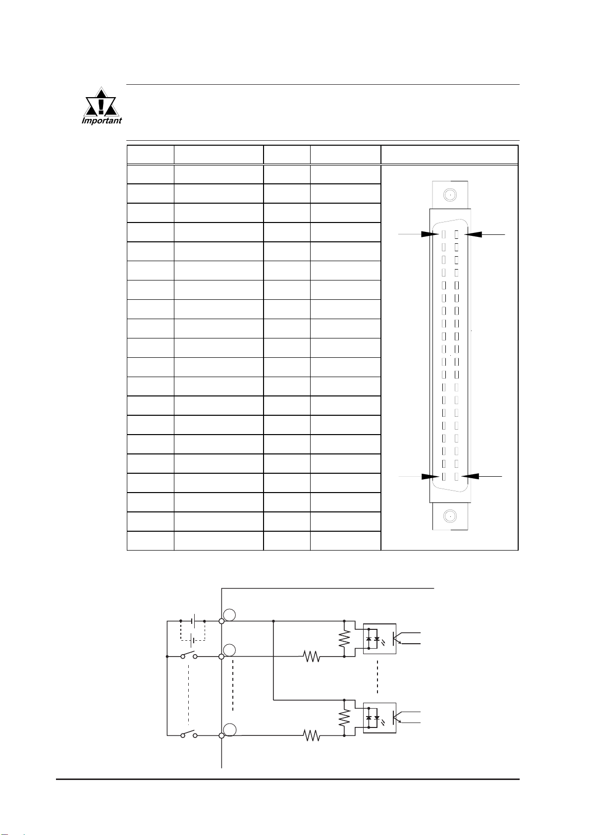
Input/Output Connector (Type B+)
This connection drawing is as seen from the LT. The cable connector will
use the A, B marks to show pin orientation. Be sure to check this orientation prior to creating your cable.
Pin Signal Name Pin Signal Name LT Connector
A 1 COM (0V :DOUT) B1 COM (24V:DIN )
A 2 COM (0V :DOUT) B2 DC 24V (DOUT)
A 3 NC B3 NC
A 4 NC B4 NC
A 5 DOUT15 B5 DIN15
A 6 DOUT14 B6 DIN14
A 7 DOUT13 B7 DIN13
A 8 DOUT12 B8 DIN12
A 9 DOUT11 B9 DIN11
A10DOUT10B10DIN10
A11 DOUT9 B11 DIN9
A12 DOUT8 B12 DIN8
A13 DOUT7 B13 DIN7
A14 DOUT6 B14 DIN6
A15 DOUT5 B15 DIN5
A16 DOUT4 B16 DIN4
A17 DOUT3 B17 DIN3
B1A1
B20A20
A18 DOUT2 B18 DIN2
A19 DOUT1 B19 DIN1
A20 DOUT0 B20 DIN0
♦ Input Circuit (Type B+)
DC24V External
Power Supply
- +
+ -
*
COM
IN
IN
B1
B5
B20
* Dotted line shows connection to source output type
Internal Circuit
Internal Circuit
LT Series User Manual2–16
Page 46
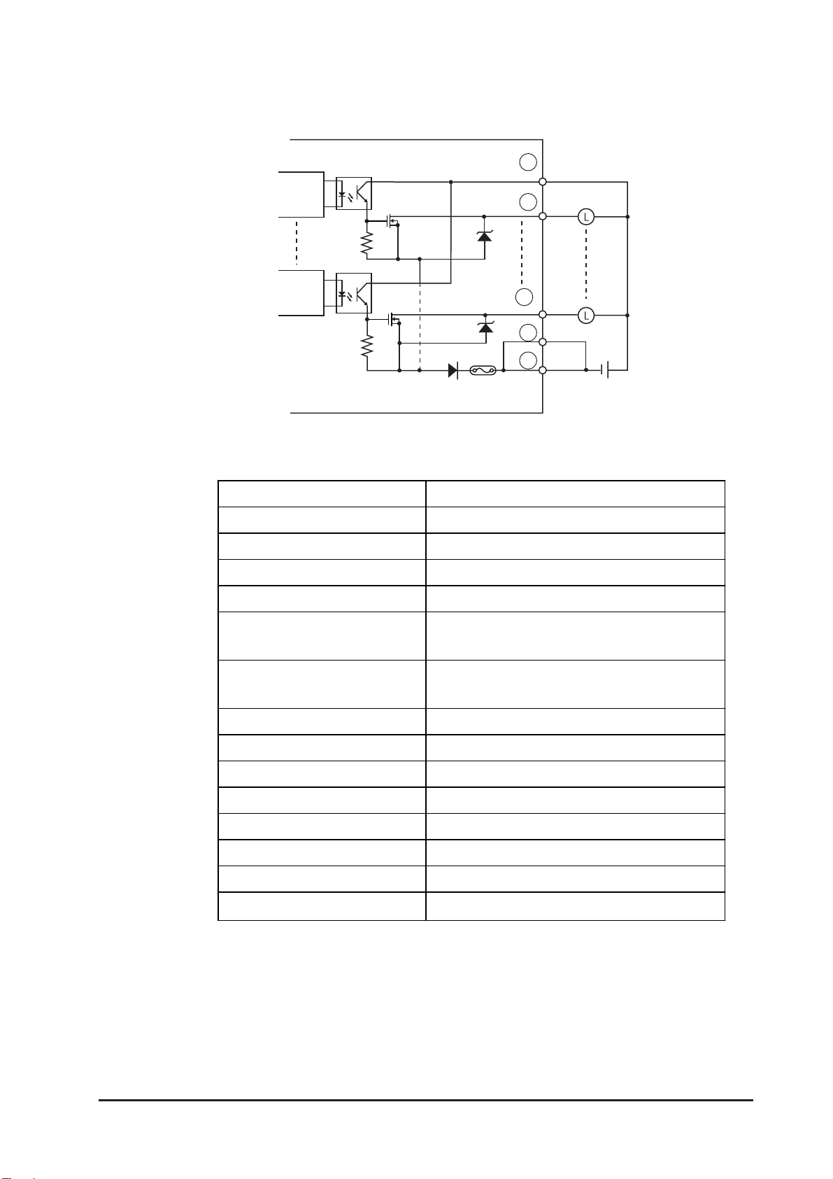
♦ Output Circuit (Type B+)
Internal Circuit
Chapter 2 – Specifications
B2
+24V
A5
OUT
Internal Circuit
♦ Input Specifications (Type B+)
Ra ted V o ltag e
Maximum Allowable Voltage
Input Method
Ra ted Cur rent
Input Resistance
Opera tion Ra nge
Input Delay Time
A20
OUT
A1
A2
COM
3.5 A
Quick
Break Fuse
DC 24V
DC 26.4V
Source/Sink Input
5.7 mA (24V )
4.2 k
Ω
ON V o lt age: 15V or more
OFF Voltage: 5V or less
OFF to ON: 1. 5 ms or less
ON to OFF: 1.5 ms or less
- +
DC 24V
External
Power
Supply
Common Lines
Common Lines Al l oca tion
Externa l Connection
Input Points
Input Signal Display
Status Display
Isola tion Method
Externa l Power Suppl y
1
16 points/1 common line
40-pin connector (used with Output section)
16
LED light s w hen each point t u rn s ON ( logical side)
None
Photocoupler Isolat ion
For Signal: DC 24V
LT Series User Manual 2–17
Page 47
Chapter 2 – Specifications
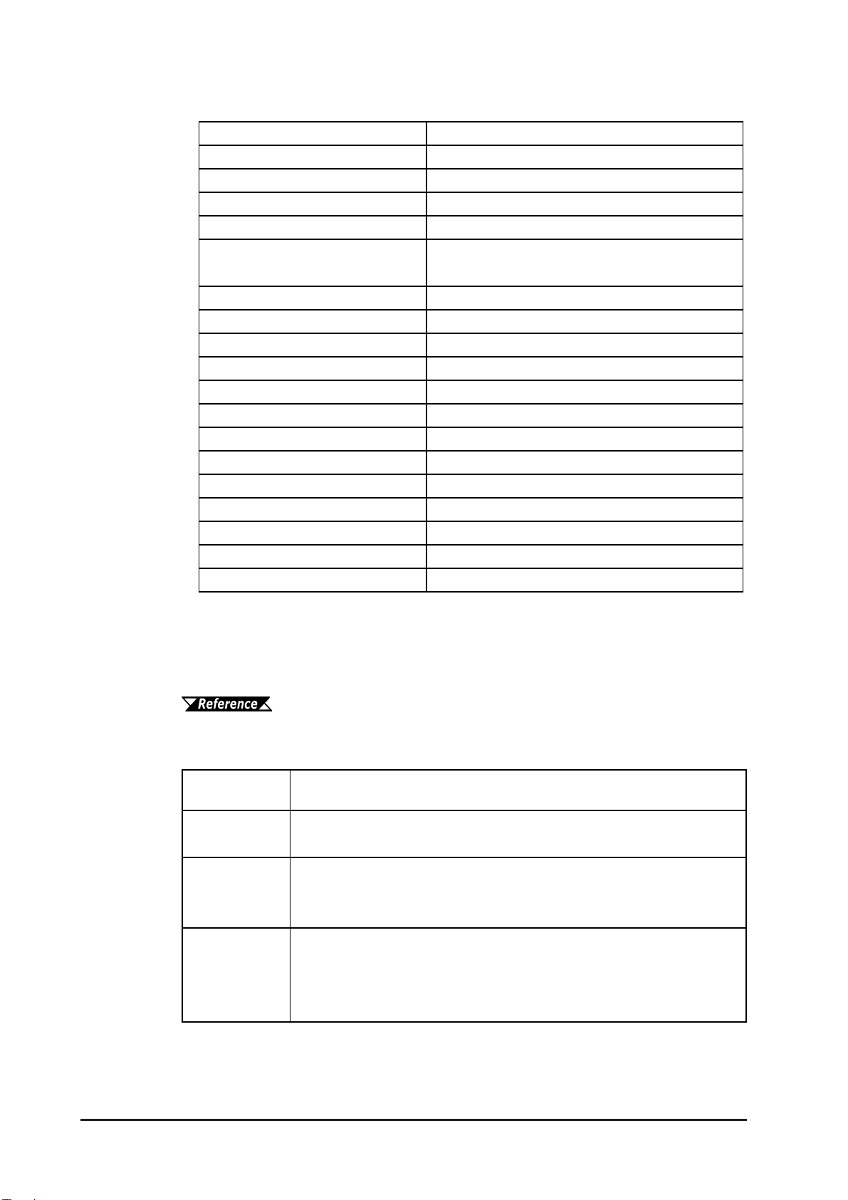
♦ Output Specifications (Type B+)
Ra ted Vo l tage
Rated Vol ta ge Range
Output Method
Maxi m um Loa d V ol ta ge
Output Volta ge Drop
Output Delay Time
Voltage Leakage (when OFF)
Type of Output
Common Lines
Common Design
Externa l Conne ction
Output Protection Type
Internal Fuse
Surge Control Ci rcui t
Output Points
Output Signal Display
Status Display Element
Isola tion Method
Externa l P ower Supply
DC 24V
DC 24V ±10%
Sink Output
0.2 A/point 1.6 A/common
1.5V or less
OFF to ON: 1ms or less
ON to OFF: 1 ms or less
0.1 mA or less
Transistor Output
1
16 points/1 common line
40-pin connector (als o us ed for Input )
Output is unprot ected
3.5 A, 125V Chip Fuse (non-replaceable)
Diode
16
LED lights when each point turns ON (logical side)
None
Photocoupler Isolat ion
DC 24V
Recommended Connectors and Covers
Digital has prepared sets of connectors and connector covers (GLC100-DIOCN01:
5 sets) and a ribbon cable crimp connector (GLC-DIOCN02: 5/set).
Section 1.3 – “Accessories”
For other types of connections, Pro-face recommends the items listed below.
Connection
Method
Solder
Crimp
Pre ssure Weld
Correspondi ng Conne ctors
(manufactured by Fujits u Takamisawa Component Limited)
FCN-361J040-AU (Connector)
FCN-360C040-B (Cover)
FCN-363J040 (Connector)
FCN-363J040- AU/S (C ont a ct)
FCN-360C040-B (Cover)
FCN-367J040- AU/F (Contact)
Recommended Cable:
Flat Cable (1.27mm pitch)
A W G#28 (Lay wire) / A W G#30 (Solid wire)
Recommended Wiring
Equivalent to AWG#22.
LT Series User Manual2–18
Page 48
Chapter 2 – Specifications
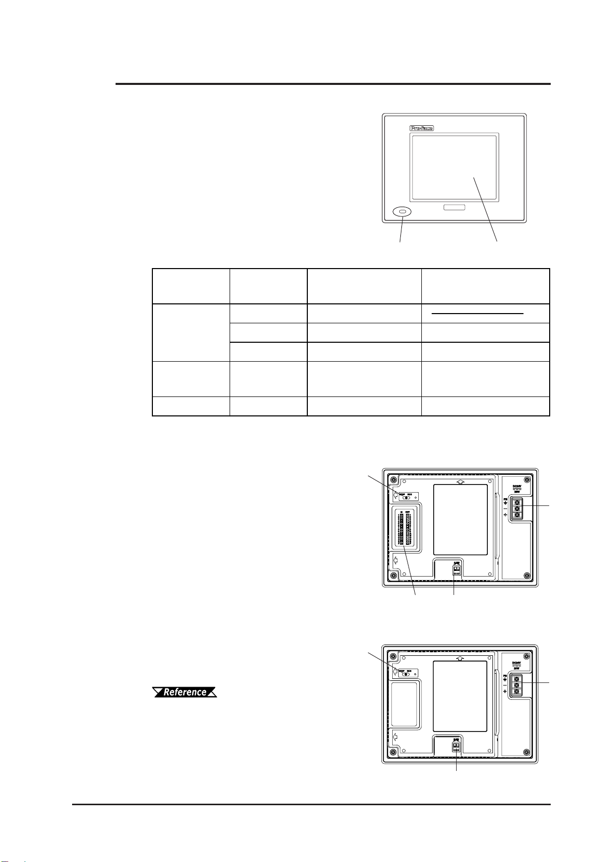
2.4 Part Names and Functions
A: Display Panel
The L T monitor screen displays user-created screens and corresponding external
device data.
B: Touch Panel
Enables the user to perform screen
change operations or input data.
C: Status LED
Indicates the LT unit’s current condition.
C
A, B
Color Indicator
Opera tion Mode
*1
Controller Operation
*2
Mode
ON OFFLINE
Green
ON In operat ion RUN
Flashing In opera t ion STOP
Green
and Re d
Red
Bot h ON In operat ion Backlight B u rno ut
ON In operat ion Major A lar m (Stop)
1 Operation Mode refers to a display and Touch Key feature.
2 Controller Operation Mode refers to the feature that executes a logic program.
D: Power Input Terminal Block
E
Connects Power Cord or Frame Ground
(FG).
E: Run/Stop Switch (When running,
LED is ON)
D
Run: Executes logic program
Stop: Stops logic program
F: Alarm Output Circuit
G F
(Type A1/ Type A2)
When a major error or a W atchdog T imer
error occurs, it turns OFF (releases) the
E
contact.
Section 2.2.5 – “External
Interface – Alarm Output”
G: Input/Output LED
(Type A1/Type A2/Type B+)
Displays the status of DIN/DOUT.
(Type B/ Type C)
F
LT Series User Manual 2–19
D
Page 49
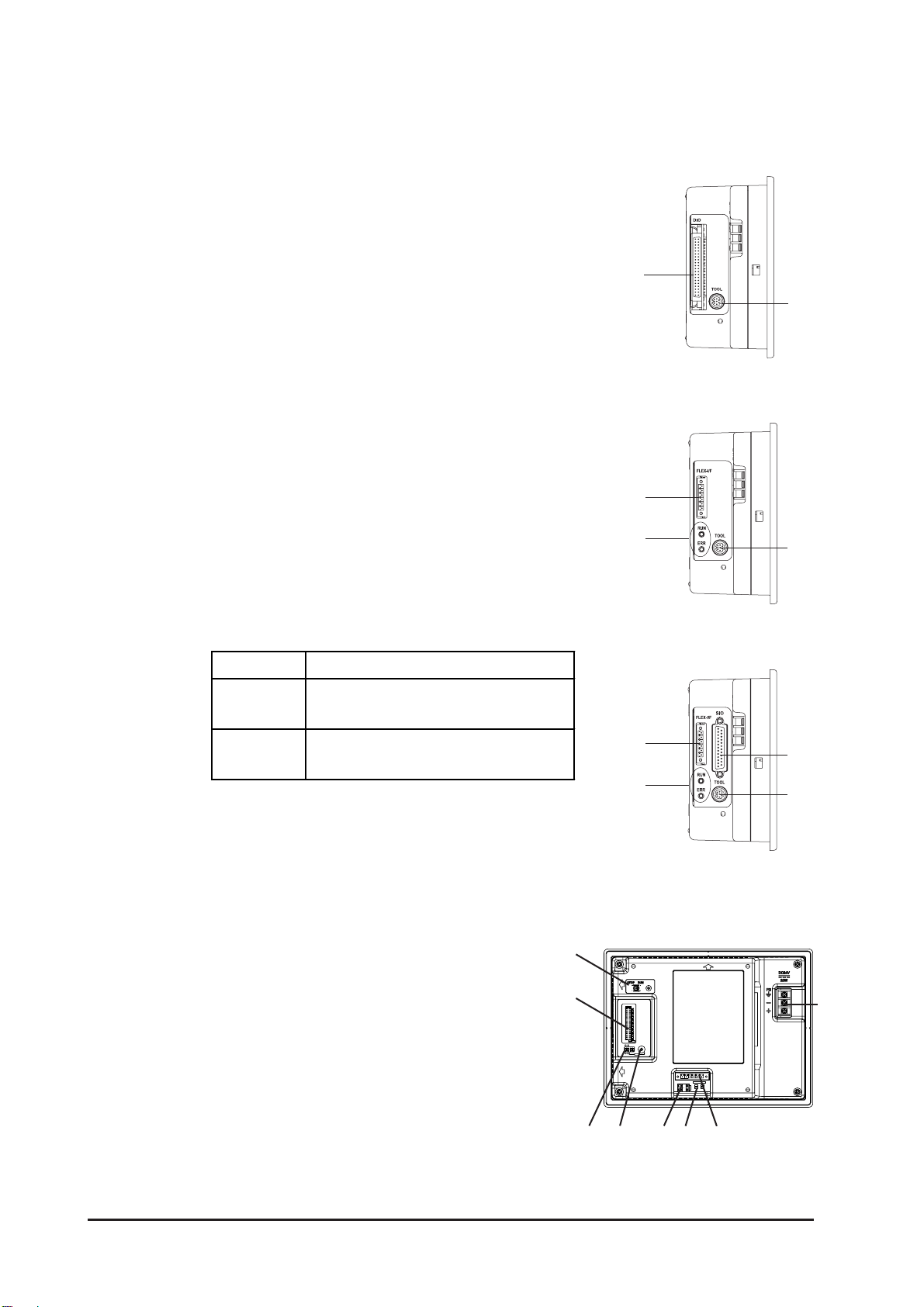
Chapter 2 – Specifications
H: Tool Connector
Connects to Data Transfer Cable, Bar Code
Reader.
I: Input/Output Connector
(Type A1/Type A2/Type B+)
Connects external Input/Output units
through the DIO connector.
I
H
The Type B+ unit’s I/O connector occupies a single S-No. on the Flex Network.
J: Flex Network I/F
(Type B/Type B+/Type C)
Connects I/O unit or Analog unit through
the Flex Network Communication Cable
K: Flex Network Status LED
(Type B/Type B+/Type C)
Flex Network I/F status LED will turn ON
or flash, according to the unit’s status.
Status LED Contents
RUN
(Green)
ERR (Red)
Turns on when Communication is
enabled.
Turns on when failure occurs in connected
I/O Unit.
L: Serial Interface (Type C)
(Type A1 / Type A2)
J
K
J
K
H
(Type B)
L
H
The RS-232C or the RS-422 Interface connects to an external device (Temperature
Controller, Inverter, etc.)
M: Dip Switches (Type B+)
These switches control the I/O connector’s
Output Hold. Also, they are used to set the
S-No.’s left-most hex digit.
N: Rotary Switch (Type B+)
Used to set the S-No.’s right-most hex
digit.
E
G
M N F
(Type C)
D
K J
(Type B+)
LT Series User Manual2–20
Page 50
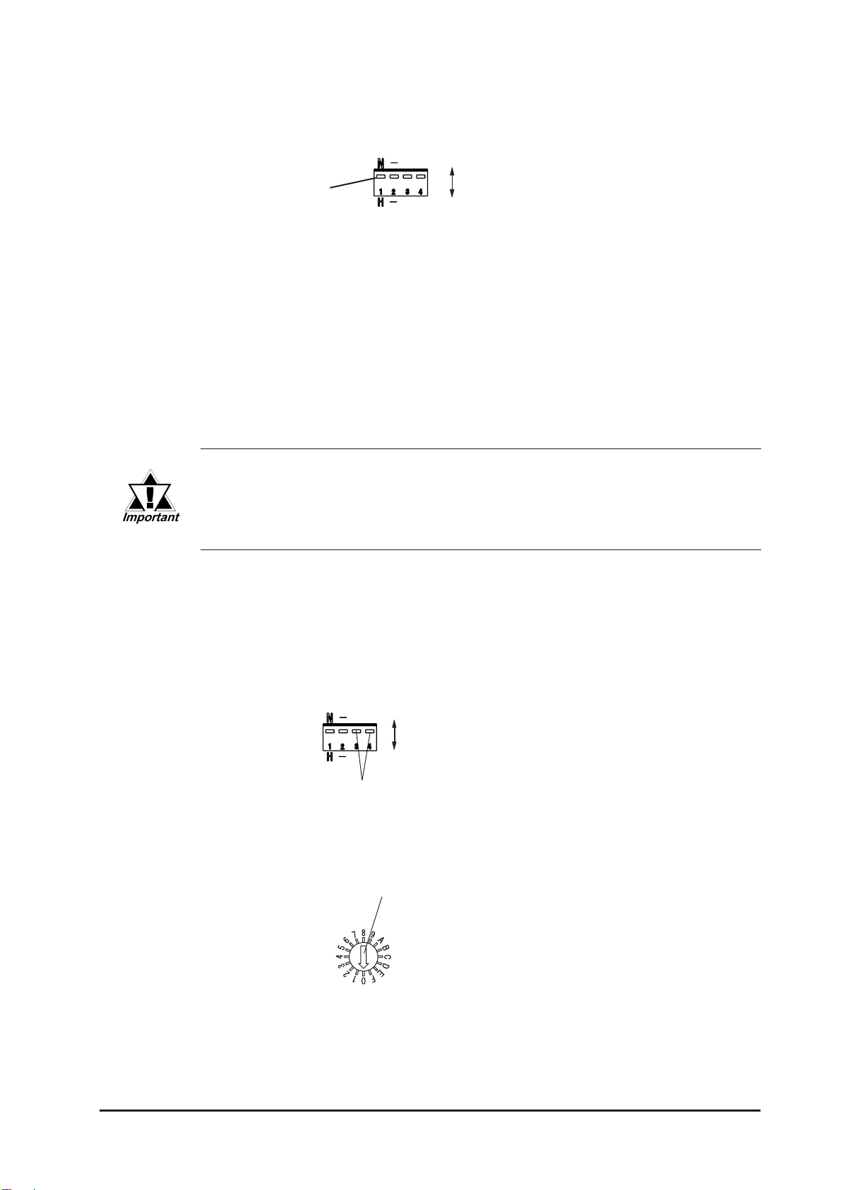
Chapter 2 – Specifications
Output Hold Settings
The left-most dip switch is used to turn this setting ON/OFF. The factory setting is
OFF (No Hold)
Output Hold OFF
Dip Switch 1
Output Hold ON
Output Hold ON (Hold)
When a communication error occurs, the unit will HOLD the output condition
received in the previous communication cycle. When the next cycle is performed
and the next command is successfully received, the output will then be changed.
Output Hold OFF (Non-Hold)
When a communication error occurs, all outputs are reset to 0 (OFF). When
normal communication is restored, the output is also restored.
When the Logic Program is changed from RUN to OFFLINE mode, the
output hold setting is turned OFF. Be sure to consider this before changing to OFFLINE mode, or resetting the unit. Also, when the unit is reset,
the I/O signal OFF timing is not fixed.
S-No. (Station Number) Setting
Station numbers from 1 to 63 are set in hexadecimal (01h to 3Fh) The factory
setting is 01h.
The hex upper digit is controlled by the two dip switches (SW3, SW4) on the right
side, via turning them ON/OFF.
ON
OFF
indicates the hex upper digit
The Rotary Switch’s arrow tip indicates the station number’s right-most hex digit
(0 to F).
The arrow's tip indicates the position
LT Series User Manual 2–21
Page 51
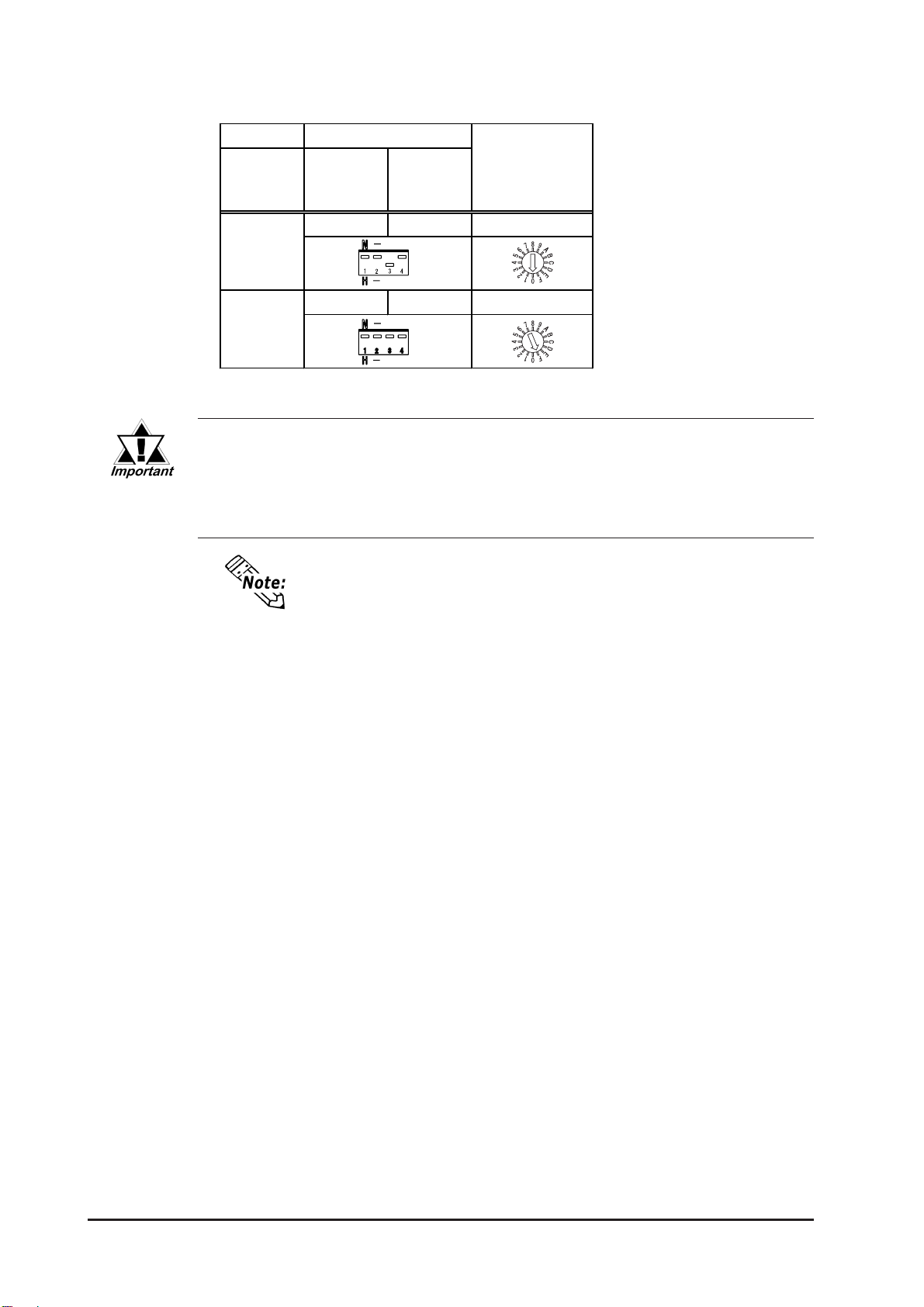
Chapter 2 – Specifications
S-No. Setting Example
S-No. Dip Switch
the 2nd
Base 10
S-No. 16
(10h)
S-No. 63
(3Fh)
• Do NOT change the S-No. while the unit is in RUN mode. Changing this
number in RUN mode could cause a malfunction. Be sure to turn the
power supply OFF prior to changing this setting.
from the
right
OFF (0) ON (1) 0
ON (1) ON (1) F
right side
Rotary
Switch
• Be sure that S-No.s do not overlap.
Use the Flex Network Driver settings to change the Flex Network data transfer speed.
LT Series User Manual2–22
Page 52
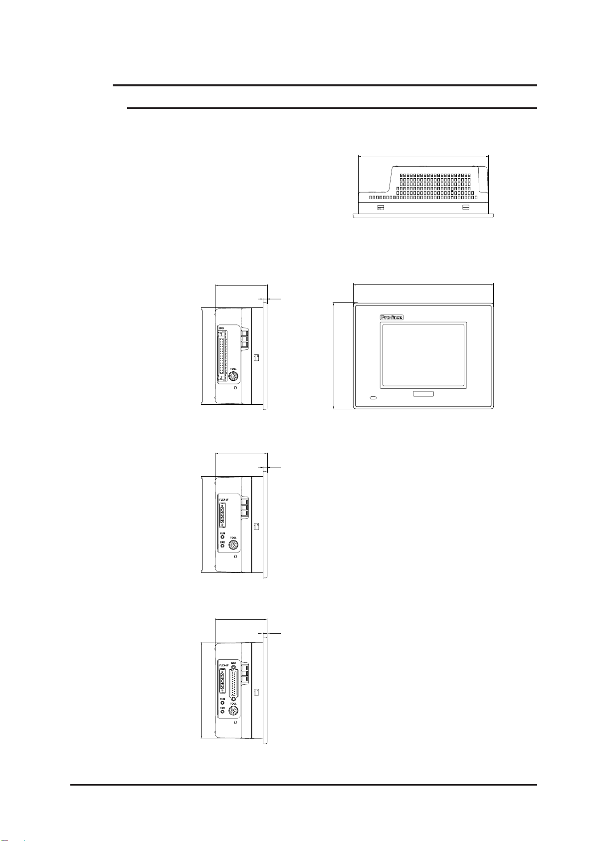
2.5 Dimensions
2.5.1 LT External Dimensions
Unit: mm [in.]
Chapter 2 – Specifications
191.2 [7.53]
Top
75.8 [2.98]
141.2 [5.56]141.2 [5.56]141.2 [5.56]
75.8 [2.98]
207 [8.15]
6 [0.24]
157 [6.18]
FrontSide (Type A1/Type A2/Type B+)
6 [0.24]
Side (Type B)
75.8 [2.98]
6 [0.24]
Side (Type C)
LT Series User Manual 2–23
Page 53
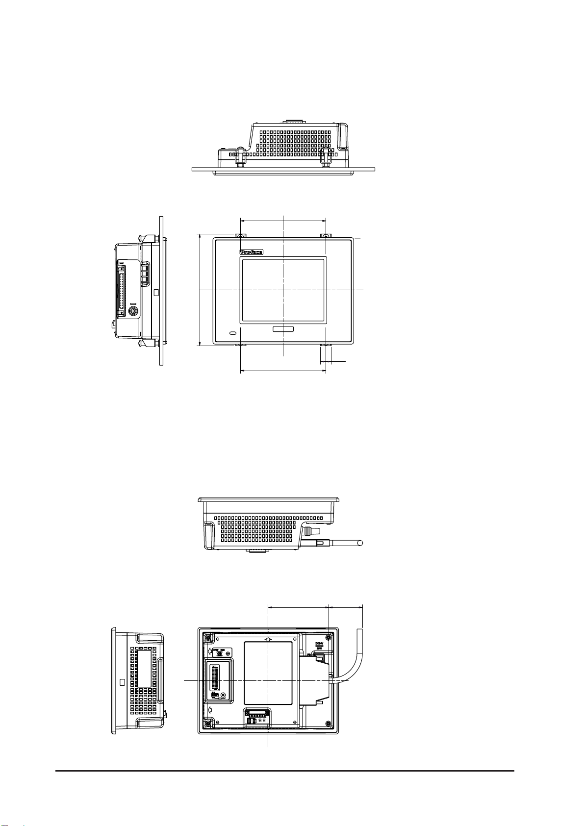
Chapter 2 – Specifications
The following drawing shows the LT unit with installation fasteners.
Unit: mm [in.]
(164 [6.46])
Top
125 [4.92]
16 [0.63]
Side
125 [4.92]
Front
The following drawing shows the LT unit with cables.
Unit: mm [in.]
Top
(50 [1.97])(90 [3.54])
Side Back
LT Series User Manual2–24
Page 54
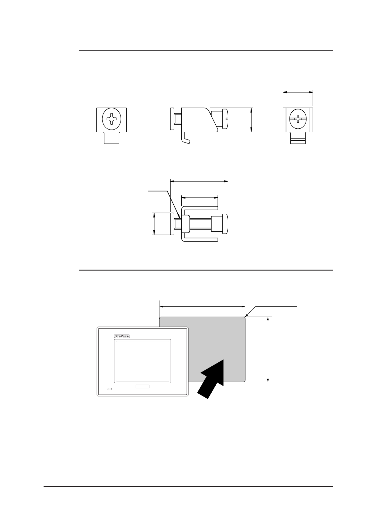
2.5.2 Installation Fasteners
Unit: mm [in.]
31 [1.22]
M5
19.5[0.77]
16 [0.63]
11 [0.43]
10 [0.39]
2.5.3 Panel Cut Dimensions
Unit: mm [in.]
+1
191.5
[7.54 ]
0
+0.04
0
less than 4–R3
0
+0.04
[5.57 ]
0
+1
141.5
2–25LT Series User Manual
Page 55

Chapter 2 – Specifications
Memo
LT Series User Manual2–26
Page 56
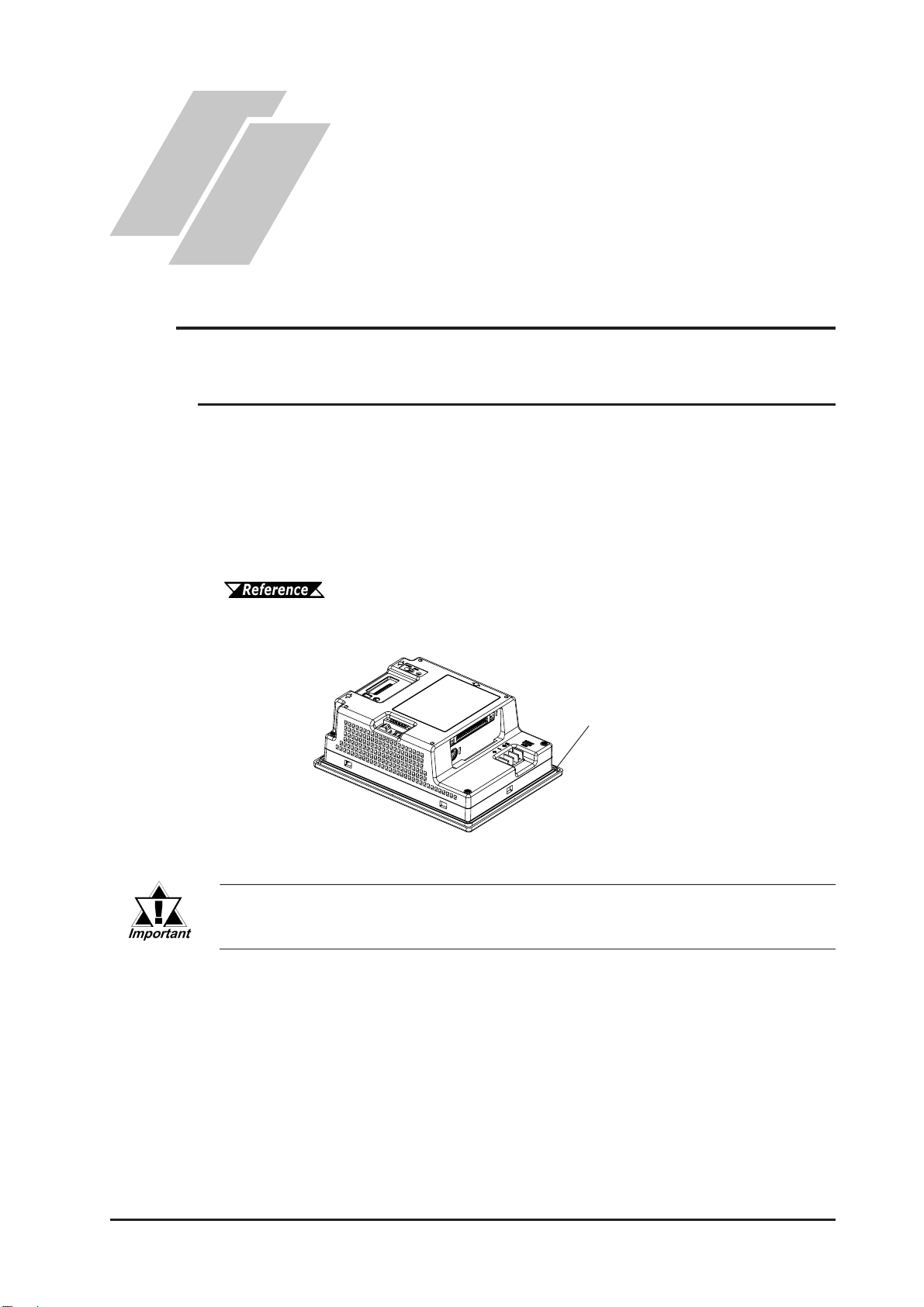
Chapter
3 Installation and Wiring
3.1 Installation
Follow the steps in this section to install the LT.
3.1.1 Installation Procedures
Attaching the Installation Gasket
Pro-face strongly recommends that you use the installation gasket to absorb
vibration as well as repel water.
Place the display panel of the LT face down on a level surface. Make sure that the
LT unit’s installation gasket is securely fitted into the groove that runs around the
perimeter of the panel’s frame.
1. Installation
2. Wiring Cautions
3. Tool Connector
For details about installing the gasket, see Section 8.1.2 – “Installation Gasket Check/Replacement.”
Installation
Gasket
Before installing the LT into a cabinet or panel, check that the Installation gasket is securely attached to the unit.
3–1LT Series User Manual
Page 57
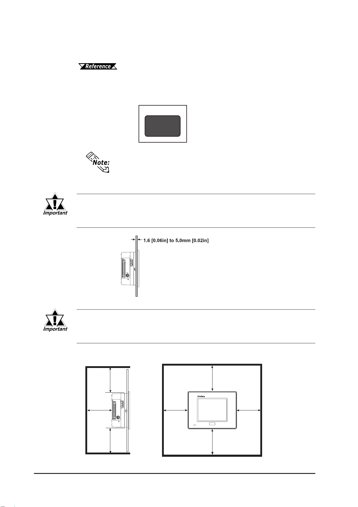
Chapter 3 – Installation and Wiring
Creating a Panel Cut
Create an opening with the correct dimensions to install the LT.
For the correct installation dimensions, see Section 2.5.3 – “L T Panel
Cut Dimensions.”
The installation gasket, installation fasteners, and attachment screws are all required when installing the LT.
Panel
Panel Cut
Area
Make sure that the installation panel or cabinet’s surface is
flat, in good condition, and has no jagged edges. Metal reinforcement strips can also be attached to the inside of the panel,
near the Panel Cut, to increase the panel’s strength.
Panel thickness should be between 1.6 and 5.0 mm (0.06 to 0.02 in.),
and should be based on the strength required to mount the LT to the
panel.
For easier maintenance and operation, and improved ventilation, install
the LT at least 100 mm (3.94 in.) away from adjacent structures and
other equipment.
Unit: mm [in]
100
[3.94]
100
[3.94]
100
[3.94]
100
[3.94]
100
[3.94]
100
[3.94]
100
[3.94]
3–2 LT Series User Manual
Page 58
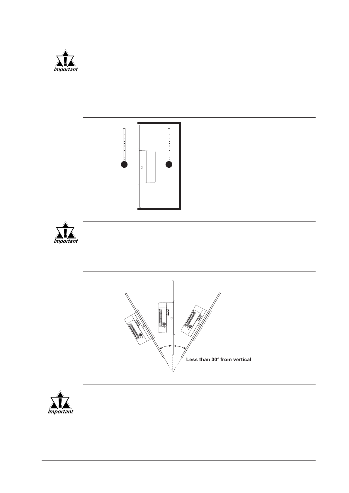
Chapter 3 – Installation and Wiring
• To prevent accidents, be sure the Operating Temperature is from 0oC to
o
50
C, and the Ambient Humidity is from 10%RH to 90%RH (Wet bulb
temperature of 39
“Ambient operation temperature,” when referring to the installation of
the LT in a cabinet or other enclosure, indicates the internal temperature of the cabinet or enclosure.
o
C or less).
Cabinet
Exterior
Cabinet
Interior
• Make sure that heat from surrounding equipment does not cause the L T
to exceed its standard operating temperature.
• When installing the LT in a vertically-inclined panel, the panel’s face
should NOT incline more than 30o.
• When installing the L T in a vertically-inclined panel, and the panel’ s face
inclines at an angle greater than 30
exceed 40
bient operating temperature is lower than 40o C.
LT Series User Manual
o
, the ambient temperature must NOT
o
C. You may need to use forced air cooling to ensure the am-
3–3
Page 59
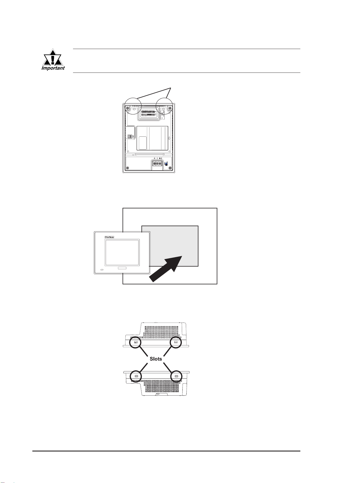
Chapter 3 – Installation and Wiring
When installing the LT vertically, position the unit so that the arrows on
the back of the LT point upwards.
Arrows
Installing the LT
1. Insert the LT into the panel cutout, as follows:
2. Insert the installation fasteners into the LT unit’s insertion slots — two slots
each, at the top and bottom of the unit (max. of 6, including sides).
3–4 LT Series User Manual
Page 60
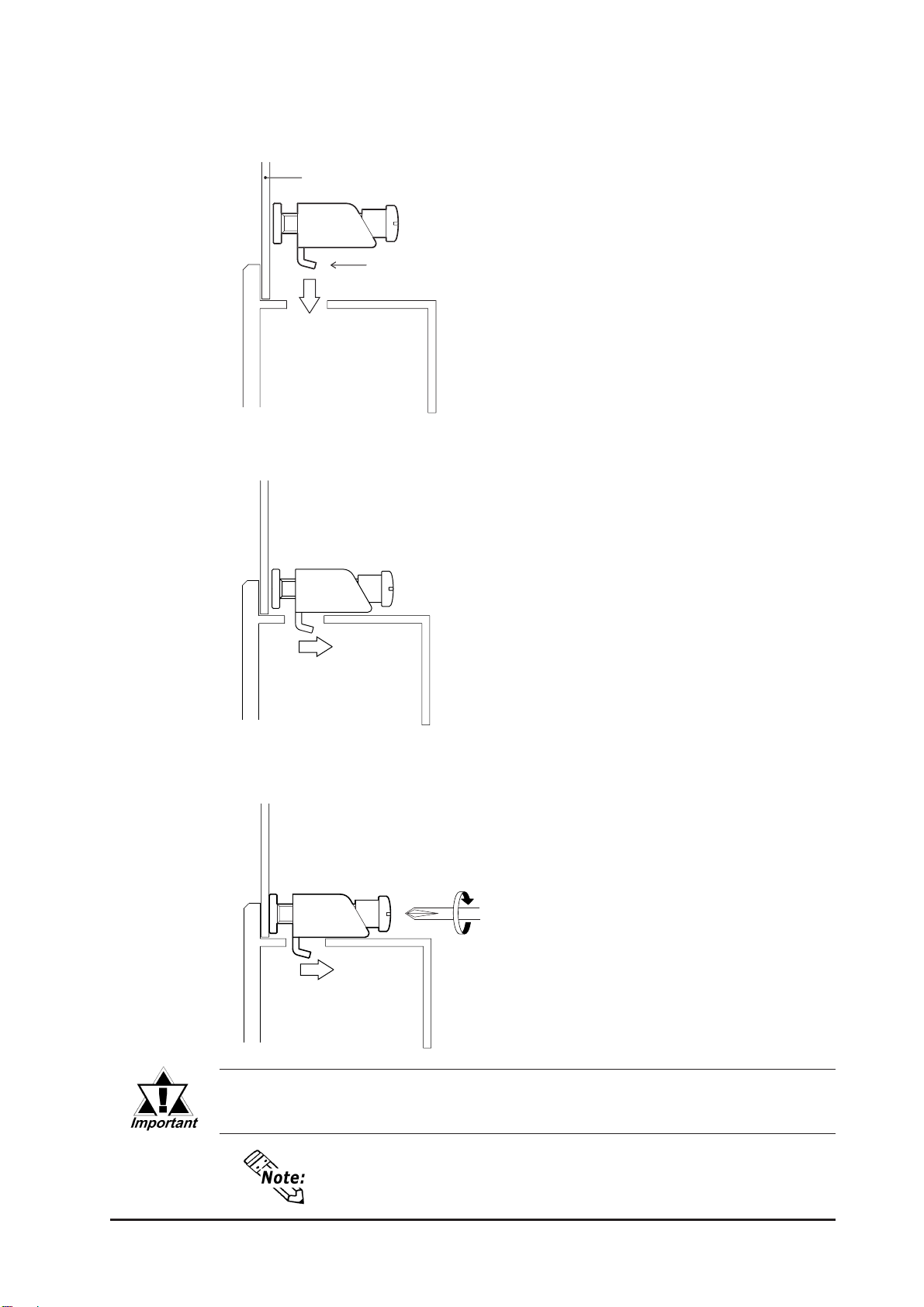
Chapter 3 – Installation and Wiring
3. Insert each of the fasteners as follows.
Installation Panel
Hook
4. Be sure to pull the fastener back until it is flush with the rear of the attachment
hole:
5. Use a Phillips screwdriver to tighten each fastener screw and secure the LT in
place.
A torque of only 0.5 to 0.6 N•m is sufficient to tighten these screws.
Excessive force may damage the LT unit.
Depending on the condition of the panel, increasing the number of installation fasteners will raise the level of water resistance.
LT Series User Manual
3–5
Page 61
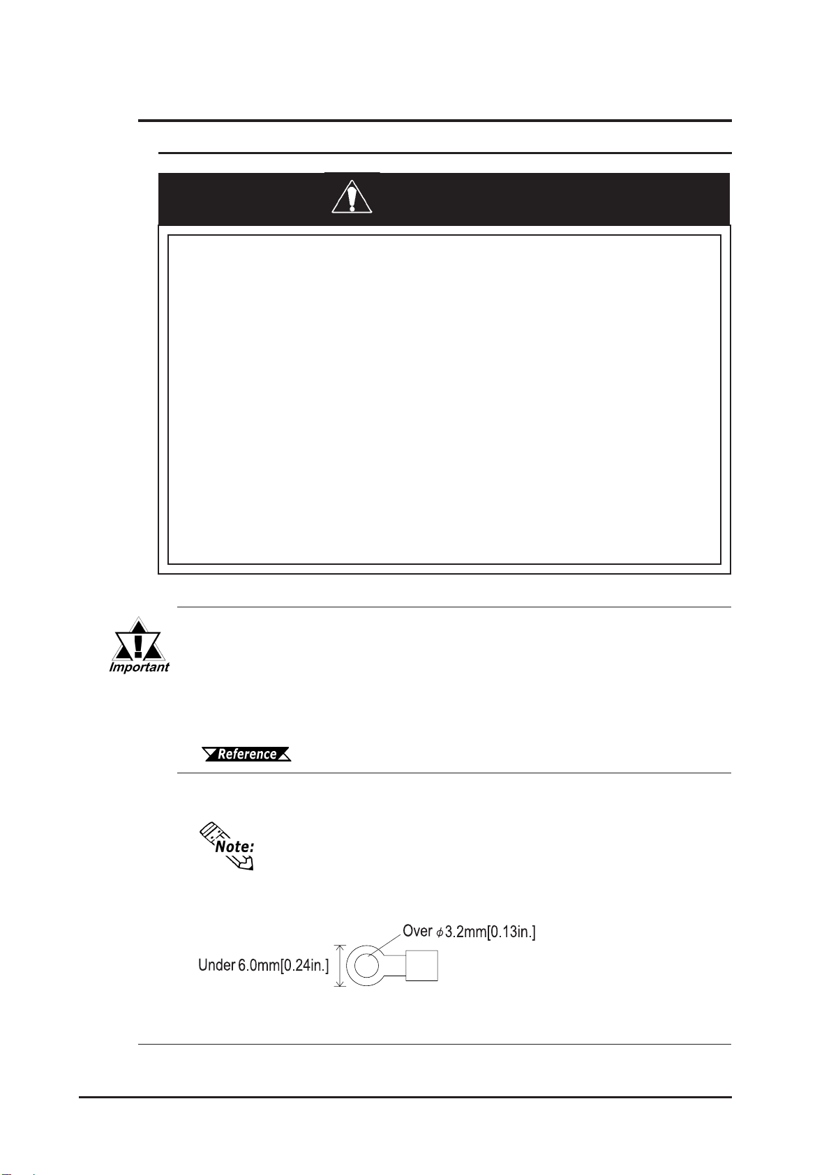
Chapter 3 – Installation and Wiring
3.2 Wiring Cautions
3.2.1 Connecting the Power Cord
WARNINGS
• T o avoid electrical shock, be sure the power cord is unplugged from the power outlet when connecting the
power terminals to the LT unit.
• The LT requires a DC 24V power supply. If the power
supply does not match the model, both the power supply and LT unit will be damaged.
• Reattach the LT Terminal Strip’s clear plastic cover
after the wiring is completed. If the cover is not installed, it may cause an electrical shock.
• Since the LT is not equipped with the power switch,
be sure to connect a breaker type switch to the LT’s
power code.
• To prevent the Ring Terminals*1 from short-circuiting when the terminal
block attachment screws are loosened, use sleeve-type Ring T erminals.
• When the FG terminal is connected, be sure that the wire is grounded.
Not grounding the LT unit will result in excessive noise. Use your
country’s applicable standard for grounding.
Section 3.2.2 – “Grounding”
• Whenever possible, use thick wires (max. 2mm2) for power
terminals, and twist the exposed wire ends when connecting the Ring Terminals.
• Use crimp-on type Ring Terminals in the following sizes:
1 Recommended Ring Terminal: V2-MS3 (manufactured by JST).
3–6 LT Series User Manual
Page 62
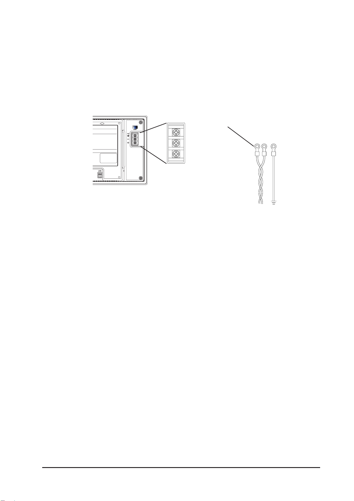
Chapter 3 – Installation and Wiring
Connecting the Power Supply Terminals
1. Make sure that the LT unit’s power cord is not plugged in to the power supply.
2. Remove the Terminal Strip’s clear plastic cover.
3. Remove the screws from the three (3) middle terminals, position the Ring
Terminals (see below), and reattach the screws. Check each wire to make sure
the connections are correct, and use only 0.5 to 0.6 N•m of force.
Crimp-on Ring Terminals
FG
–
+
Power T erminal Block
Rear of the LT Unit
4. Reattach the Terminal Strip’s clear plastic cover.
+–FG
DC 24V
LT Series User Manual
3–7
Page 63
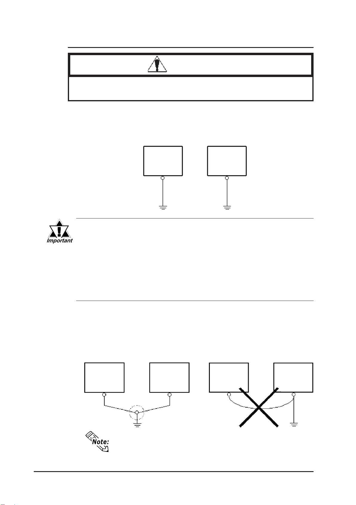
Chapter 3 – Installation and Wiring
3.2.2 Grounding
CAUTION
Do not use common grounding, since it can lead to an accident or machine breakdown.
Connect the FG terminal found on the back of the LT to an exclusive ground
(diagram A).
(A) Exclusive Grounding (BEST)
LT
• Make sure that the grounding resistance is less than 100
• FG and SG terminals are internally connected in the LT. When connecting to another device, be sure to not create an SG shorting loop in your
system.
• The grounding wire should have a cross-sectional area of at least 2mm
Create the grounding point as close to the L T unit as possible, and keep
the wires as short as possible. Replace all thin wires with thicker wires,
and place them in a duct.
Other
Equipment
ΩΩ
Ω.
ΩΩ
If exclusive grounding is not possible, use a common connection point (dia. B).
2
.
(B) Common Grounding (OK)
LT
Equipment
If the equipment does not function properly when grounded,
disconnect the ground wire from the FG terminal.
Other
(C) Common Grounding (Not OK)
LT
Other
Equipment
3–8 LT Series User Manual
Page 64
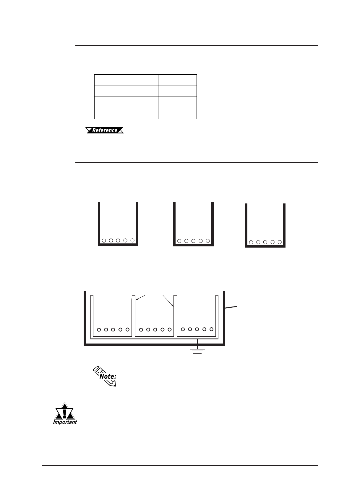
Chapter 3 – Installation and Wiring
3.2.3 Flex Network Communication Cable
The following Flex Network Communication Cables are used to connect the LT
unit to the Flex Network Unit (T-junctions cannot be used).
Model Length
FN-CABLE2010-31-MS 10m
FN-CABLE2050-31-MS 50m
FN-CABLE2200-31-MS 200m
For detailed information about Flex Network cables or Flex Network units, refer to the Flex Network User Manual.
3.2.4 I/O Signal Line Cautions
To help prevent noise and interference problems, separate all control, communication and power lines by placing them in a separate ducts.
Duct for I/O Signal Lines
Duct for Control Lines
Duct for Power Lines
If different wires must be placed in the same duct, separate them with an earthed/
grounded divider.
Grounded
Separators
Duct
I/O Signal
Lines
Lines
Power LinesControl
Earth/Ground
(non-conducting
resin/plastic)
• Use noise-reducing external wiring methods to increase overall system
reliability.
• T o prevent power surges or noise interference, use ducts to separate all
DC I/O or current circuit wires from communication cables.
• To prevent malfunctions due to noise, communication cables must be
wired separately from high-frequency lines and power lines such as
high-voltage lines, high-current lines, and inverters.
LT Series User Manual
If the lines cannot be separated, use shielded lines and create a ground from the shield line.
3–9
Page 65

Chapter 3 – Installation and Wiring
3.2.5 Installation Cautions
A problem in the external power supply or an LT unit failure can lead to operation
failures.
Since these types of failures can affect the entire system, as a preventive measure,
be sure to set up a protection circuit (such as an Emergency Stop, Protection
Network, Interlock, or System Design Circuit) in areas where potential failures
may occur .
Examples of protection circuits that ensure the system’s reliability include the
following:
Failsafe Electrical Circuits
When designing failsafe circuits, be aware of possible malfunctions resulting from
differences in the startup times of the control device connected to LT output unit
(especially the DC power supply), the LT unit’s system, and the program. When
using a remote I/O, create a logic program to check the terminal status.
For example, connect an electrical voltage relay coil to the LT output unit power
supply circuit and to any connected control devices’ power circuit, then connect
their contacts to the LT input unit. Design the circuit so that it checks for an ON
signal from the electrical voltage relay using a logic program, then executes the
ladder program of the control device connected to the LT output unit.
Input Voltage
The power supply must be DC 24V (between DC 20.4V and DC 28.8V).
3–10 LT Series User Manual
Page 66
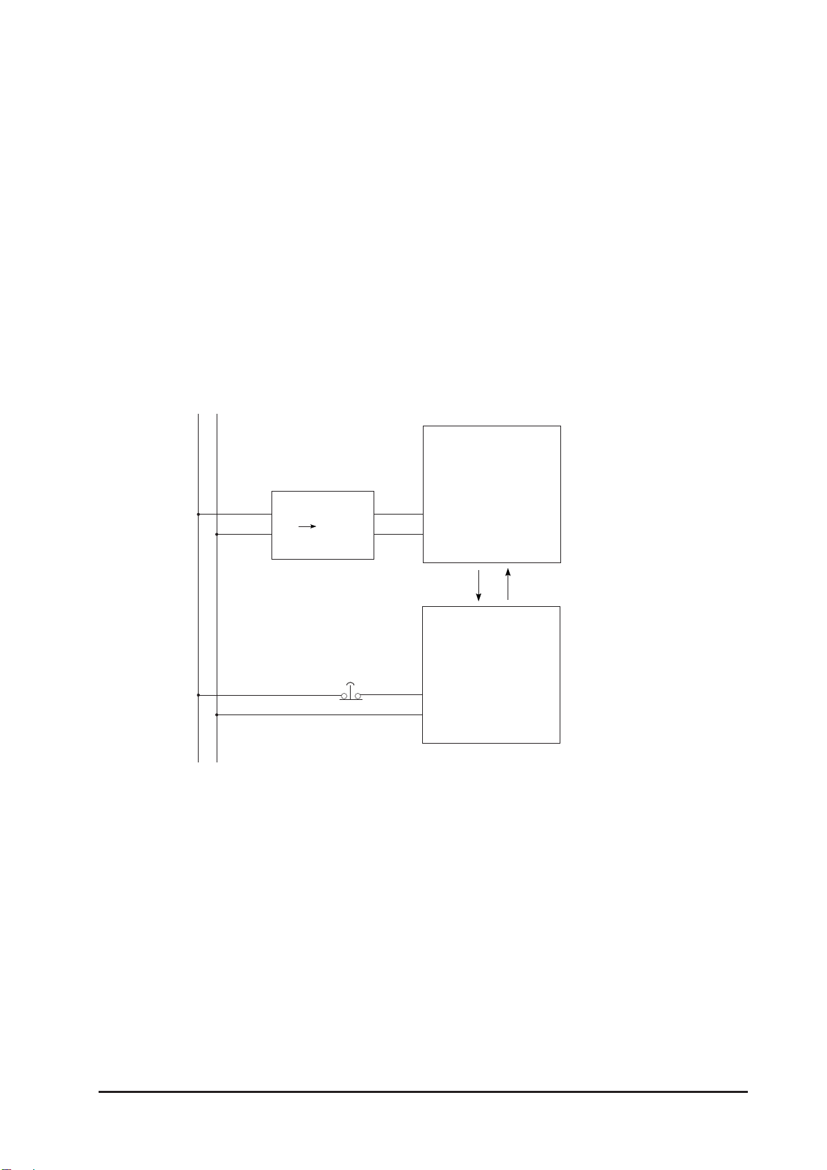
Chapter 3 – Installation and Wiring
Power Interruptions
When a power supply interruption is 10 ms or longer, the LT unit's power will also
stop. Also, when a power interruption occurs, operation will stop even while a
command is being issued.
For example, if the power is cut while an FMOV command is sending data in 100word units, command execution will stop.
When designing the program, allow for the possibility of a power interruption.
Emergency Stop Circuits
Do NOT send an Emergency Stop signal to the LT , and do NOT use the LT unit’s
internal software to process an Emergency Stop signal.
As shown below, be sure to create the Emergency Stop circuit outside the LT.
Power source
AC DC 24V
Emergency Stop Button
B contact
LT
Output
Input
Controlled
System
LT Series User Manual
3–11
Page 67
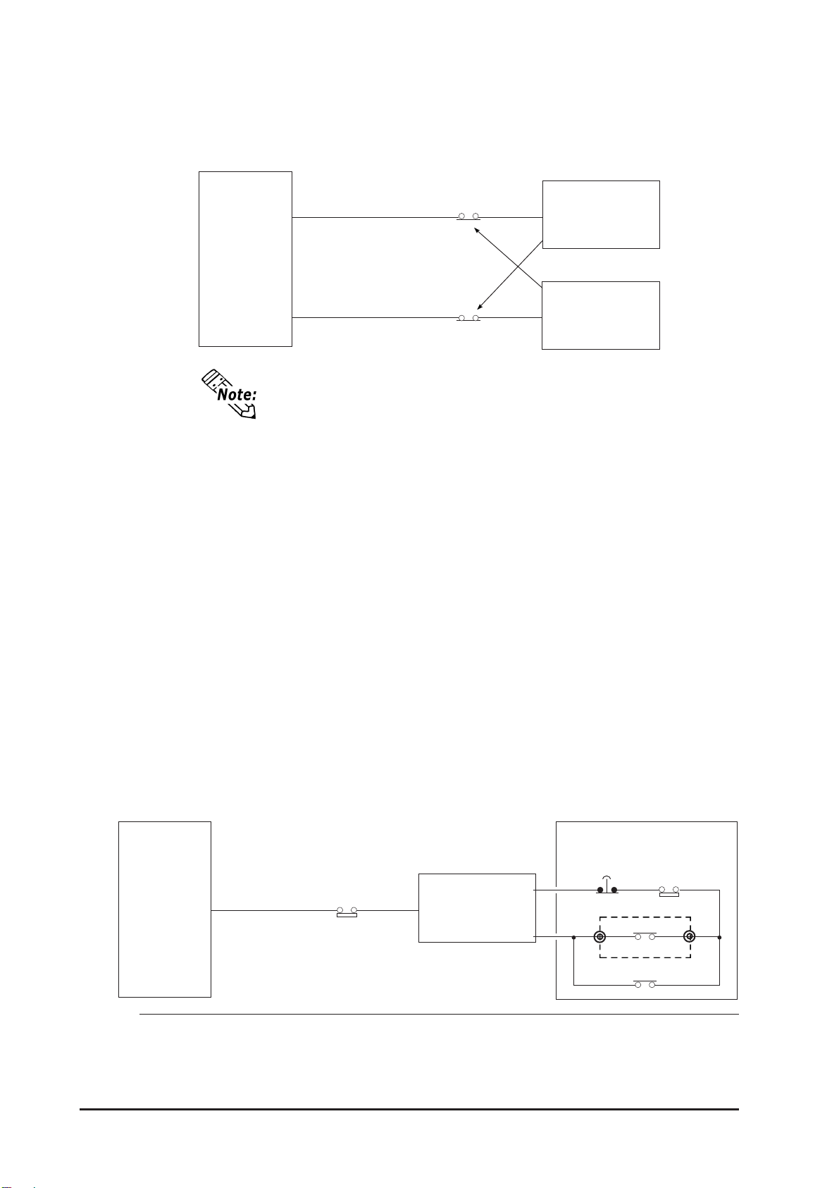
Chapter 3 – Installation and Wiring
Interlock Circuit 1
Create an interlock circuit outside the LT (below), to control a motor’s forward/
reverse rotation circuit using an LT or external device connection.
Auxiliary B contact of electromagnetic
switch for motor reverse rotation
Motor rotation signal
LT
For example, an electromagnetic switch for forward and reverse motor rotation could be turned ON and OFF at the same time. Therefore, when the
main contact for the power circuits of both the forward and the reverse motor
rotation are turned ON and OFF at the same time, there is a possibility that
an R Phase and a T Phase short circuit will occur. Please use the above
interlock, or a mechanical interlock equipped with an electromagnetic switch,
when designing a forward/reverse rotation circuit.
(forward)
Motor rotation signal
(reverse)
Auxiliary B contact of electromagnetic switch for motor forward
rotation
After the LT or external device runs the program, the timing of
the ON/OFF signals to the output device is carried out simultaneously.
Electromagnetic
switch for motor
forward rotation
Electromagnetic
switch for motor
reverse rotation
Interlock Circuit 2
If there is a possibility that an LT failure could cause an accident, use an external
hardware device to include a failsafe element in the design of the interlock circuit.
For example, if the system first needs to stop the Travel Motor whenever the Unit
Travel Limit Switch is activated, include the Unit Travel Limit Switch in the LT
input. The following circuit uses a hardware method to ensure that the Travel
Motor is stopped.
This applies to hardware; do NOT rely on software to process the interlock design.
Error monitoring circuit
LT
Unit Travel
Limit Switch
Travel Motor Control Signal
Travel Motor
Control Circuit
Emergency
Stop Switch
LT Unit alarm connection
LT Alarm Interpolation Circuit
Unit Travel
Limit Switch
*1
*2
1 When the LT discovers major errors such as Watchdog Timer Error, set up the LT unit's
alarm so that it turns all relay output OFF.
2 The relay output remains OFF until the LT system starts. In this case, the external
supervisory monitoring circuit has to recognize that the LT is not yet operating.
3–12 LT Series User Manual
Page 68
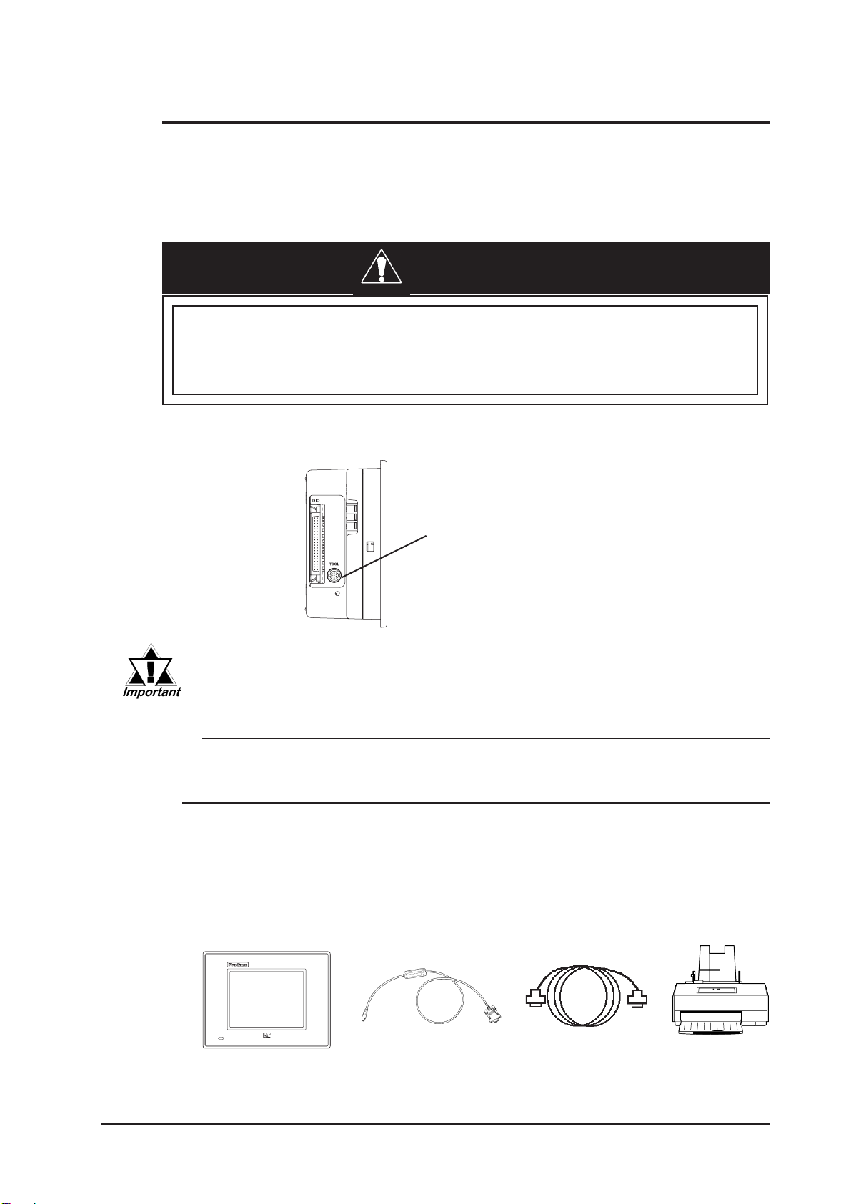
Chapter 3 – Installation and Wiring
3.3 Tool Connector
A data transfer cable or a bar-code reader can be attached to the LT unit’s tool
connector. A serial printer can be connected with a data transfer cable and a usercustomized conversion cable. The location of the LT unit’s tool connector is
shown in the following diagram.
WARNING
To prevent electrical shock, unplug the LT unit’s power
cord from the main power supply prior to attaching or
detaching any LT connectors.
Side View
Tool Connector
When the Bar Code Reader uses a separate power supply:
• Turn the Bar Code Reader ON before turning the LT ON.
• Turn the LT OFF before turning the Bar Code Reader OFF.
3.3.1 Serial Printer Connection
Overview
The LT unit outputs to a printer via the tool interface. Use the optional data transfer cable to connect to the user-customized conversion cable, and connect that
cable to the serial printer's connector.
LT Series User Manual
LT
Data Transfer Cable Conversion Cable
(user-created)
Serial Printer
3–13
Page 69
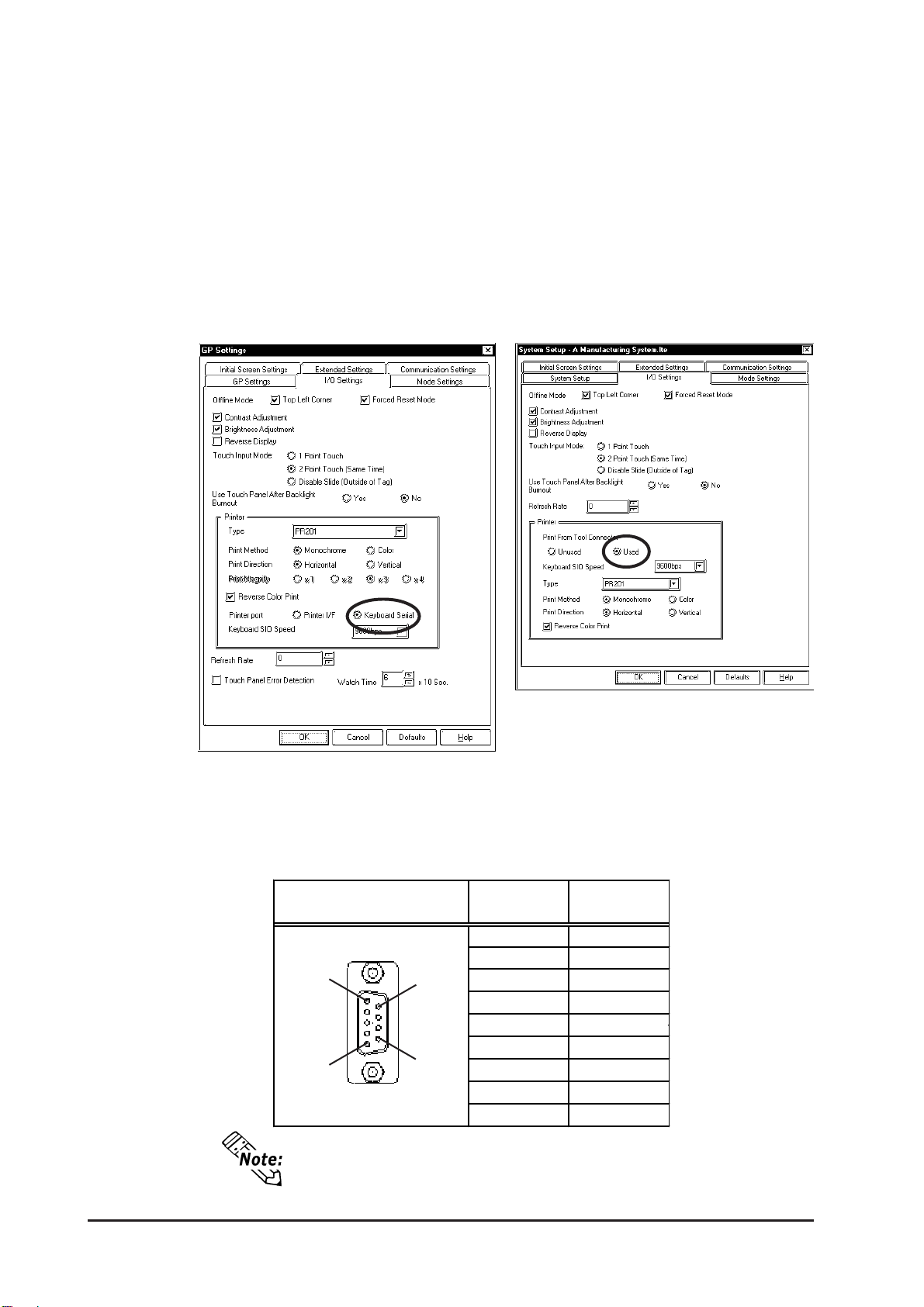
Chapter 3 – Installation and Wiring
Project Manager Setup
Select [Screen/Setup]-[System Setup] in the Project Manager. The printer output
can be executed via Tool Connector by configuring the settings on the I/O Settings
tab of the [System Setup] dialog box as shown below.
C-Package: Select the Keyboard Serial option for the Printer port setting.
LT Editor: Select the Used option for the Print from Tool Connector setting.
Depending on the connected serial printer, the Type setting and the Keyboard SIO
Baud Rate setting will differ.
C-Package LT Editor
Data Transfer Cable (Dub 9-Pin) Specification
The data transfer cable (Model: GPW-CB02) uses a socket-type connector. The
cable’s pins are assigned as follows:
Pin Assignments Pin No. Signal Name
1DTR
1
5
Use inch type set screws (#4-40 UNC).
6
9
2TXD
3RXD
4DSR
5GND
6RTS
7CTS
8RTS
9
3–14 LT Series User Manual
Page 70
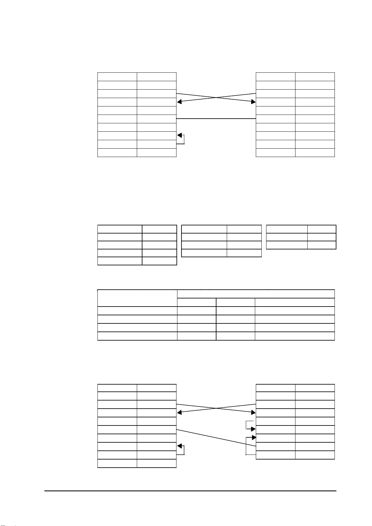
Chapter 3 – Installation and Wiring
HP Laser Jet 4PJ Printer
Conversion Cable Wiring Diagram
Printe rData Tra nsfer Cabl e (Dsub 9-Pin)
Pin No. Signal Name Pin No. Signal Name
1DTR 1
2TXD 2 TD
3RXD 3 RD
4DSR 4DSR
5GND 5GND
6RTS 6DTR
7CTS 7
8RTS 8DTR
99
Printer Type Settings Area – Type and Keyboard SIO Baud Rate
T ype: HP Laser Jet II
Keyboard SIO Baud Rate: 9600bps
Printer Settings
Se rial M enu PCL Menu Job Me nu
Serial
Protocol
Baud Rate
RobustXon
DTR P o larity
Available Printout Features
RS-232
Xo n/ Xof f
9600
OFF
HI
Font Source
Font No.
Size
Symbol
The printout features available with the LT unit are as follows:
Japanese I-ASCII Korean / Taiwanese / Chinese
Screen Hard Copy O O O
Print Alarm Message O O O
Real-time Log Data Print O O O
Print Log Data (Single Block) O O O
NADA Electronics TP-651G Printer (Ver. 1.3)
Conversion Cable Wiring Diagram
Pin No. Signal Name Pin No. Signal Name
1DTR 1 FG
2TXD 2 SD
3RXD 3 RD
4DSR 4RTS
5GND 5CTS
6RTS 6DSR
7CTS 7 SG
8RTS 20DTR
9
I (build-in)
1
12
WIN3.1
Ava ila bilityPrintout Fea ture s
Resolution
Serial
Timeout
Printe rData Tra nsfer Cable (Dsub 9-Pin)
600
PCL
15
LT Series User Manual
3–15
Page 71
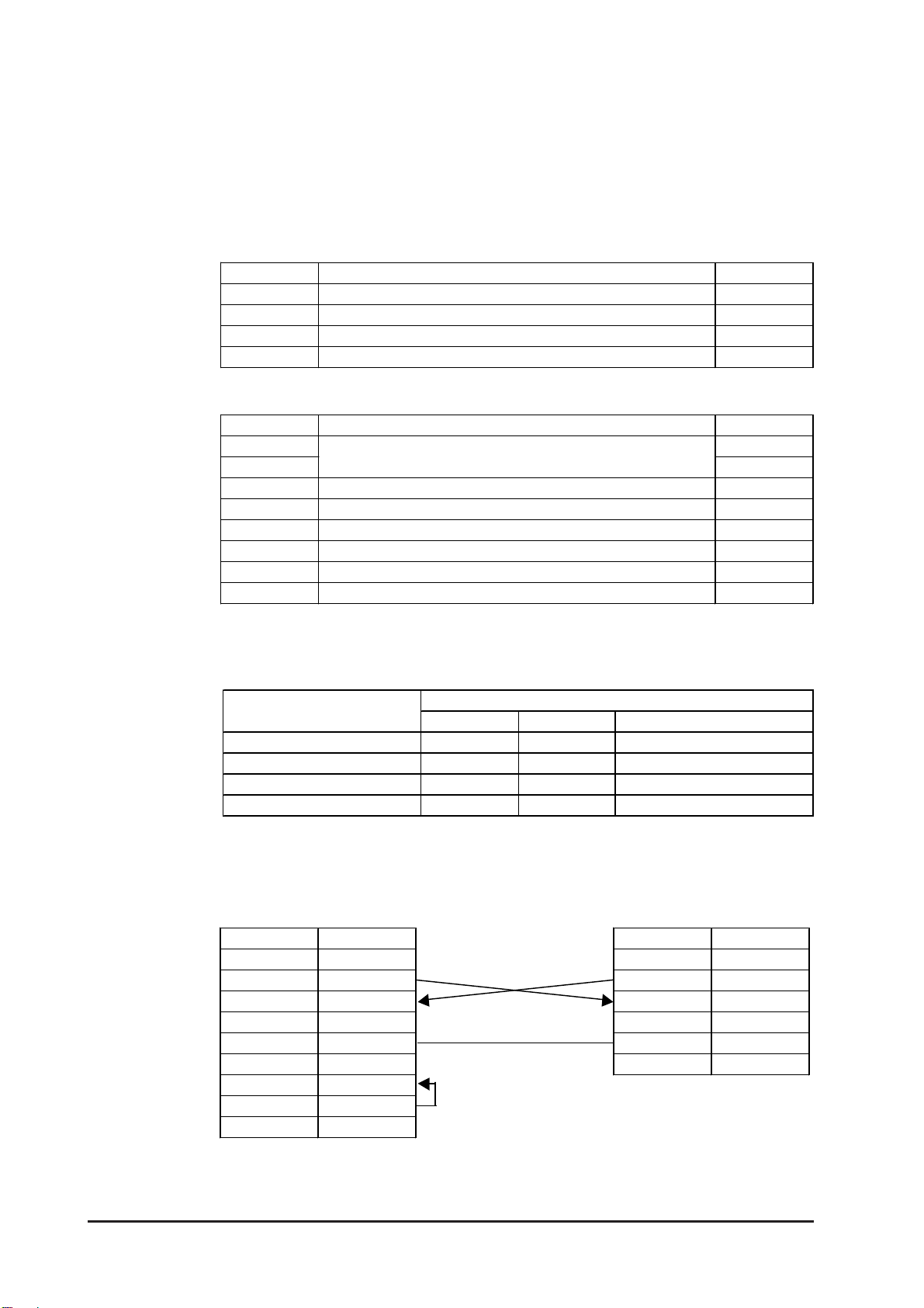
Chapter 3 – Installation and Wiring
Printer Type Settings Area – Type and Keyboard SIO Baud Rate
Type: Epson (High Quality)
Keyboard SIO Baud Rate: 19200bps
Printing Method: monochrome
Printer Settings
DIP S W1
Switch Feature ON/OFF
SW1- 1 LISTER P PR INT OFF
SW1-2 Buffer Full Print OFF
SW1-7 Graphic Double Height Printing ON
SW1-8 Exclusive Graphic 800 x 600 dot printing OFF
DIP S W2
Switch Feature ON/OFF
SW2-1 ON
SW2-2 ON
SW2-3 Dat a Bit Length: 8 bits OFF
SW2-4 Parity: Invalid OFF
SW2- 5 Parity: EVEN OFF
SW2-6 Stop Bit: 1 bit OFF
SW2-7 XON /XOFF TYPE ON
SW2-8 Print Interval: 1 second OFF
Baud Rate: 19200bps
Available Printout Features
The printout features available with the LT unit are listed as follows:
Ava ila bilityPrintout Fea ture s
Japanese I-ASCII Korean / Taiwanese / Chinese
Screen Hard Copy O O O
Print Alarm Message O O O
Real-time Log Data Print O O O
Print Log Data (Single Block) O O O
EPSON TM-U210PD Printer
Conversion Cable Wiring Diagram
Pin No. Signal Name Pin No. Signal Name
1DTR
2TXD 2TXD
3 R XD 3 R XD
4DSR 4 RTS
5GND 7GND
6RTS 20DTR
7CTS
8RTS
9
PrinterData Tra nsfer Cable (Dsub 9-Pin)
3–16 LT Series User Manual
Page 72
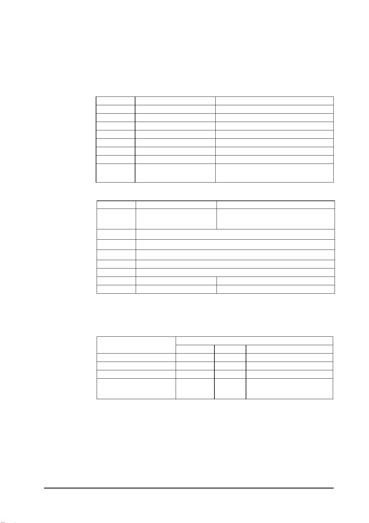
Chapter 3 – Installation and Wiring
Printer Type Settings Area – Type and Keyboard SIO Baud Rate
Type: EPSON (High Quality / High Speed)
Keyboard SIO Baud Rate: 9600bps
Printer Settings
DIP Switch Set 1
Switch Function ON/OFF
SW1-1 Data recepti on error Prints"?" marks
SW1-2 Receive buffer capacity Approx. 1K bytes
SW1-3 Handshaking XON/XOFF
SW1-4 Word length 8bits
SW1-5 Parity check No
SW1-6 Parity sel ection Odd
SW1-7 Baud rate 9600bps
SW1-8 Busy condition Sets the print er to BUSY when it i s off l i ne or
when the receive buffer is full
DIP Switch Set 2
Switch Function ON/OFF
SW2-1
SW2-2
SW2-3
SW2-4
SW2-5
SW2-6
SW 2-7 I/ F pin 6 reset signal Disabled
SW 2-8 I/ F pin 25 reset s ignal Enabled
Pr int column sele ctio n 7x 9
40/33
font / 9x9 f ont
Int ernal use. S et t ing must not be changed (fixed to OFF).
Int ernal use. S et t ing must not be changed (fixed to OFF).
Undefined.
Int ernal use. S et t ing must not be changed (fixed to OFF).
Int ernal use. S et t ing must not be changed (fixed to OFF).
Available Printout Features
Printout features available with the LT unit are as follows:
Japanese I-A S CII Korean / Taiwanese / Chinese
Screen Hard Copy X X X
P r i nt Alar m Me ssa g e X O X
Real-time Log Data Print X O X
Print Log Da t a
(Single B lock)
XO X
Ava ila bilityPrintout Fea ture s
LT Series User Manual
3–17
Page 73
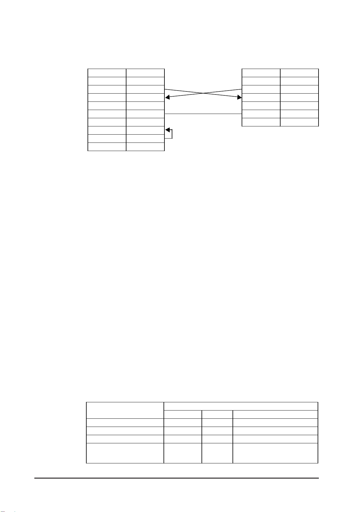
Chapter 3 – Installation and Wiring
CUSTOM FT190SP Printer
Conversion Cable Wiring Diagram
Pin No. Signal Name Pin No. Signal Name
1DTR
2TXD 2TXD
3RXD 3RXD
4DSR 4RTS
5GND 7GND
6RTS 20DTR
7CTS
8RTS
9
Printer Type Settings Area – Type and Keyboard SIO Baud Rate
Type: Epson (High Quality/High Speed)
Keyboard SIO Baud Rate: 19200bps
PrinterData Tra nsfer Cable (Dsub 9-Pin)
Printer Settings
SET UP DEFAULT:
40 COLUMNS (font 9x24)
PRINT = REVERSE
MODE = LITTLE
FONT 2
CR-LT IGNORE CR
SPEED/CURRENT = LOW
BUFFER 1K BYTE
SERIAL POR T SELECTED
BAUD RATE = 9600
PROTOCOL = 8, N, 1
FLOW CONTROL = XON-XOFF
PRINT KEY TRANSMIT $0D
Available Printout Features
The following table lists printout features available with the I-ASCII font.
Japanese, Korean, Taiwanese, and Chinese fonts are not available.
Ava ila bilityPrintout Fea tures
Japanes e I-ASCII K or ean / Taiwanese / Chines e
Screen Hard Copy X X X
P rint Ala rm Messa g e X O X
Real-t ime Log Data P r int X O X
Print Log Dat a
(Single Block)
XO X
3–18 LT Series User Manual
Page 74
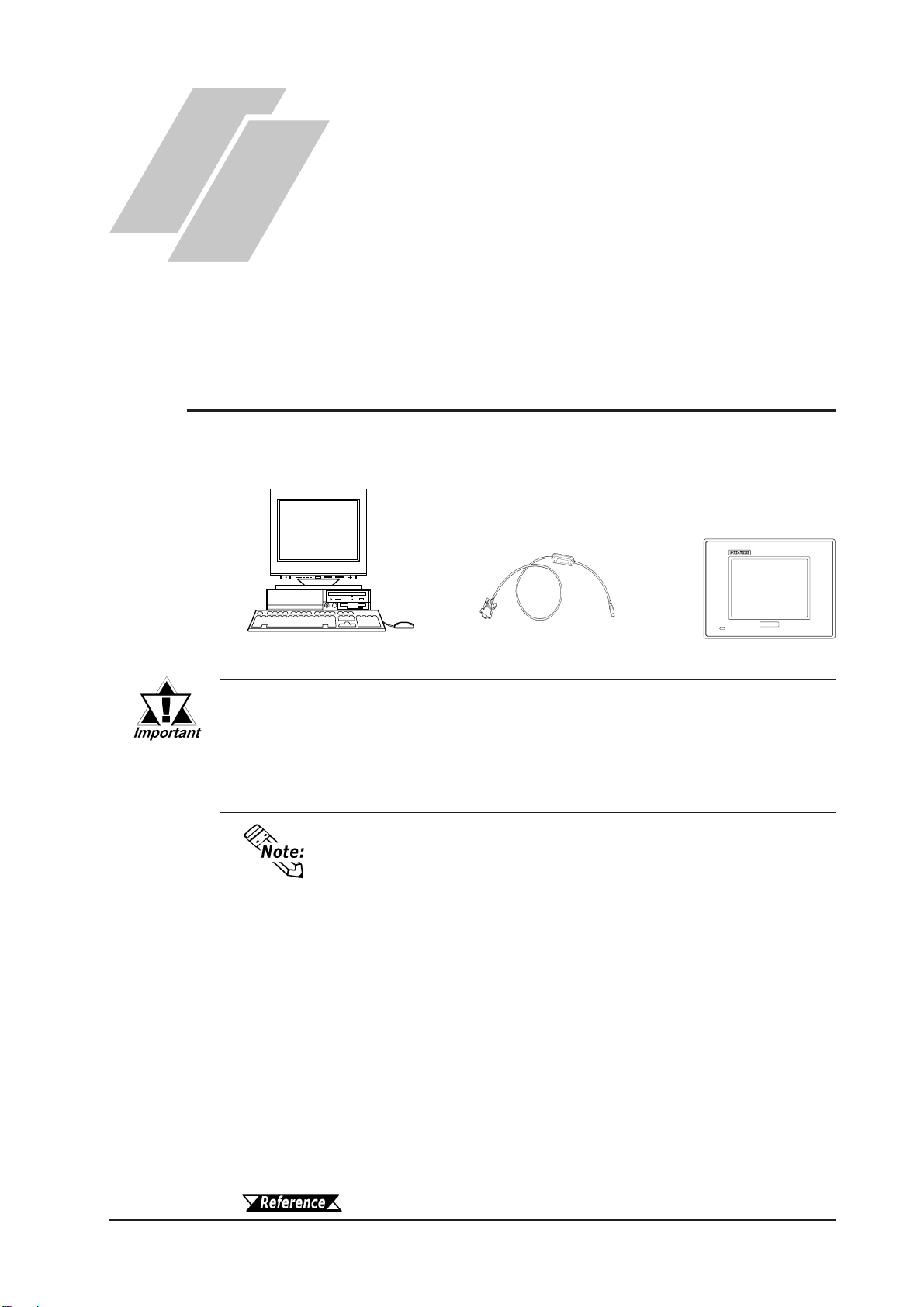
Chapter
4 Data Transfer
This chapter explains how to transfer data created with the LT Editor/C-Package
to or from the LT unit. Transfer data via the data transfer cable between the LT and
the PC.
4.1 Data Transfer Cable
The following diagram illustrates the connection between your PC and the LT
with the data transfer cable.
1. SERIAL DATA TRANSFER
2. OFFLINE Mode Main Menu
3. INITIALIZATION
PC
T o PC’s serial port/
USB port
Sending the project file to the L T requires the Data Transfer cable (GPWCB02), which is sold separately.
Also, the I/F conversion adapter is not included with the LT. However, if
necessary, you can purchase this adapter at a computer supply store.
• Pro-face’s serial data transfer cable (GPW-CB02) and USB
data transfer cable (GPW-CB03) are sold separately. However, the data transfer cable package does NOT include
the PC’s interface conversion adapter.
• When using the PC with the Dsub 25-pin socket (female)
interface, a connector conversion adapter is required. Use
the straight-line type of conversion adapter.
Recommended adapters:
Abel Co. AA833
Sanwa Supply Co. D09-9F25F
• When using a PC equipped with a half-pitch, 14-pin socket
interface, a conversion adapter is required.
Recommended adapter:
Loas Co. ZR01-024
Data Transfer Cable/
USB Data Transfer Cable*
T o LT unit’s tool connector
1
LT
1 Software version limitations apply.
For details, USB Data Transfer Cable Installation Guide.
4–1LT Series User Manual
Page 75
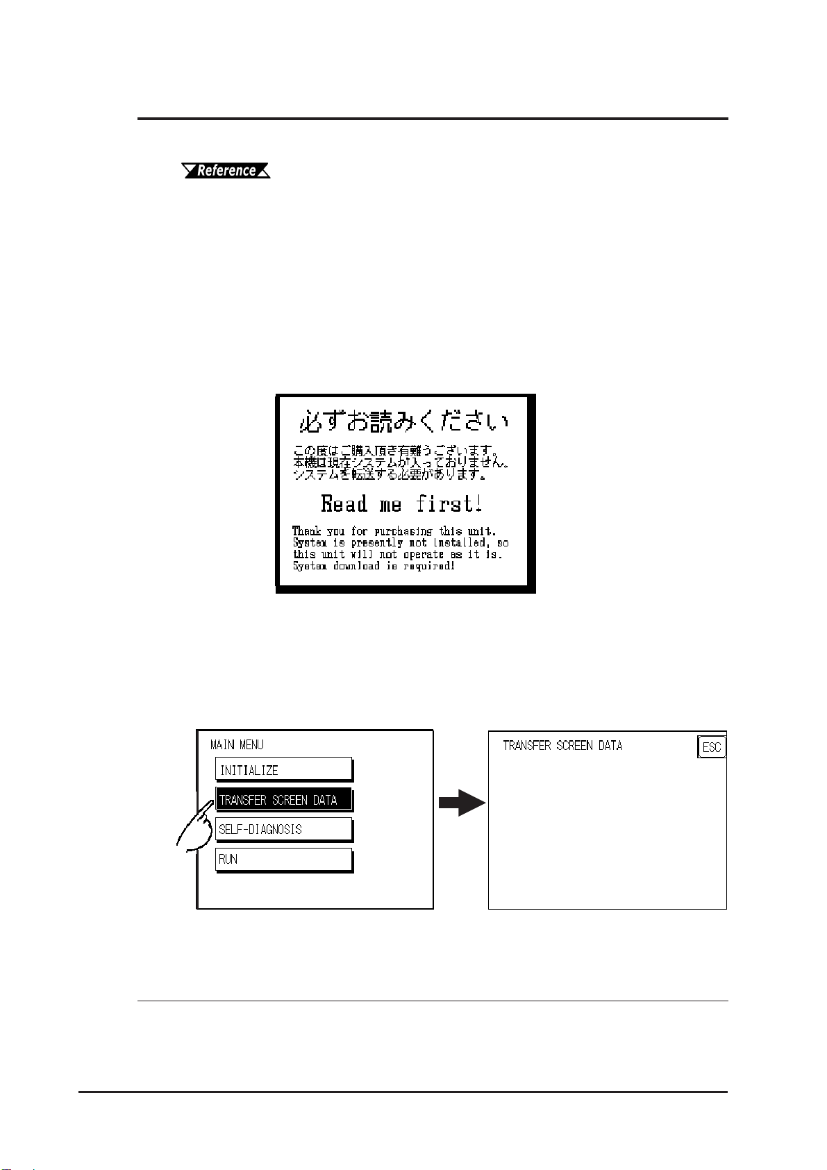
Chapter 4 – OFFLINE Mode
4.2 Transferring Screen Data
Transfer screen data from your PC via the LT Editor/C-Package.
For details about the operation of the LT Editor/C-Package, r efer to
the LT Editor Operation Manual – Screen Creation Guide (included
with the LT Editor software) and the GP-PRO/PBIII Operation
Manual (included with the C-Package software).
Transferring Data to a New LT
Connect the LT to your PC with the data transfer cable, and then turn the L T ON.
The “Read me first” screen appears on the LT unit, and then automatically
changes to the TRANSFER SCREEN DATA screen. After this screen appears,
you can transfer screen data from the LT Editor/C-Package to the L T.
Completing Data Transfer
When transferring screen data from the LT Editor/C-Package, the screen automatically switches to TRANSFER SCREEN DATA. If the screen does not switch to
TRANSFER SCREEN DATA, select TRANSFER SCREEN DATA mode.
1 The LT must be prepared for the data transfer process before the data can be
transferred. To do this, be sure to download the system program and the protocol
program from the LT Editor/C-Package to the LT.
*1
4–2 LT Series User Manual
Page 76
Chapter 4 – OFFLINE Mode
During data transfer, the SETUP TRANSFER, NOW TRANSFERRING – PLEASE
WAIT,
sages disappear, the screen data transfer is completed.
When the screen data transfer is completed, if you do not need to set up the LT, the
screen designated in INITIALIZE | SCREEN SET UP | INITIAL SCREEN NO. ap-
pears, and the screen changes to operation (RUN) mode.
You can cancel data transfer at any time using your LT Editor/C-Package
software’ s Transfer screen.
and NOW WRITING – PLEASE WAIT messages appear. When these mes-
Interrupting the screen data transfer can lead to an LT startup error.
During screen data transfer, do NOT:
• disconnect the LT unit’s power supply
• turn off the PC
• disconnect the LT unit’s transfer cable
If the LT Editor/C-Package’s SYSTEM SETUP data is transferred to the LT, the OFFLINE mode INITIALIZE data will be
overwritten.
4–3LT Series User Manual
Page 77

Chapter 4 – OFFLINE Mode
Memo
4–4 LT Series User Manual
Page 78
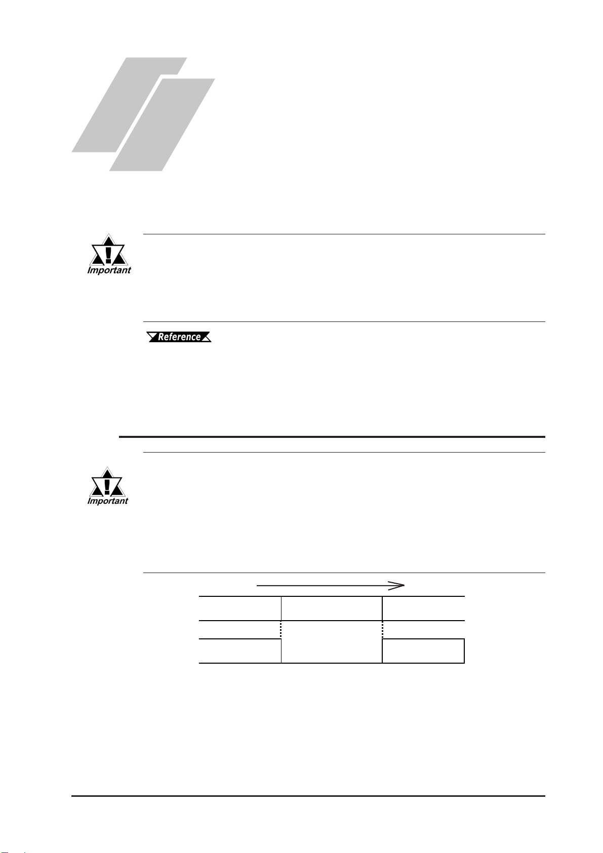
Chapter
5 OFFLINE Mode
OFFLINE Mode provides access to the LT unit’s Initialize menu, Self-Diagnosis
menu, and other LT features. You need to change the LT to OFFLINE mode before
you can use any of these features.
OFFLINE mode is unavailable in a new LT until the necessary System data
has been transferred from your LT Editor/C-Package. To transfer system
data, the LT must be ON. When the screen data files are transferred from
the LT Editor/C-Package to the LT, the System screen data is also automatically sent.
1. Entering OFFLINE Mode
2. OFFLINE Mode Main Menu
3. INITIALIZATION
4. SELF-DIAGNOSIS
For information about transferring data to the LT, refer to the LT Editor
Operation Manual – Screen Creation Guide (included with the LT
Editor software) and the GP-PRO/PBIII Operation Manual (included
with the C-Package software).
5.1 Entering OFFLINE Mode
• When the Logic Program is changed from RUN to OFFLINE mode, the
output hold setting is turned OFF. Be sure to consider this before
changing to OFFLINE mode, or resetting the unit. Also, when the unit
is reset, the I/O signal OFF timing is not fixed.
• Be aware that when changing a Logic Program from RUN to OFFLINE
mode, regardless of the current output hold setting, the LT unit’s and
the I/O signals’ processing is as follows:
LTCondition RUN OFFLINE RUN
ON
Out Signal
OFF
Output from Logic
Program
OFF
In order to initialize the LT or perform any self-diagnostics, you must change the
LT to OFFLINE mode. The following explanation explains the two ways to enter
this mode.
Output from Logic
Program
5–1LT Series User Manual
Page 79
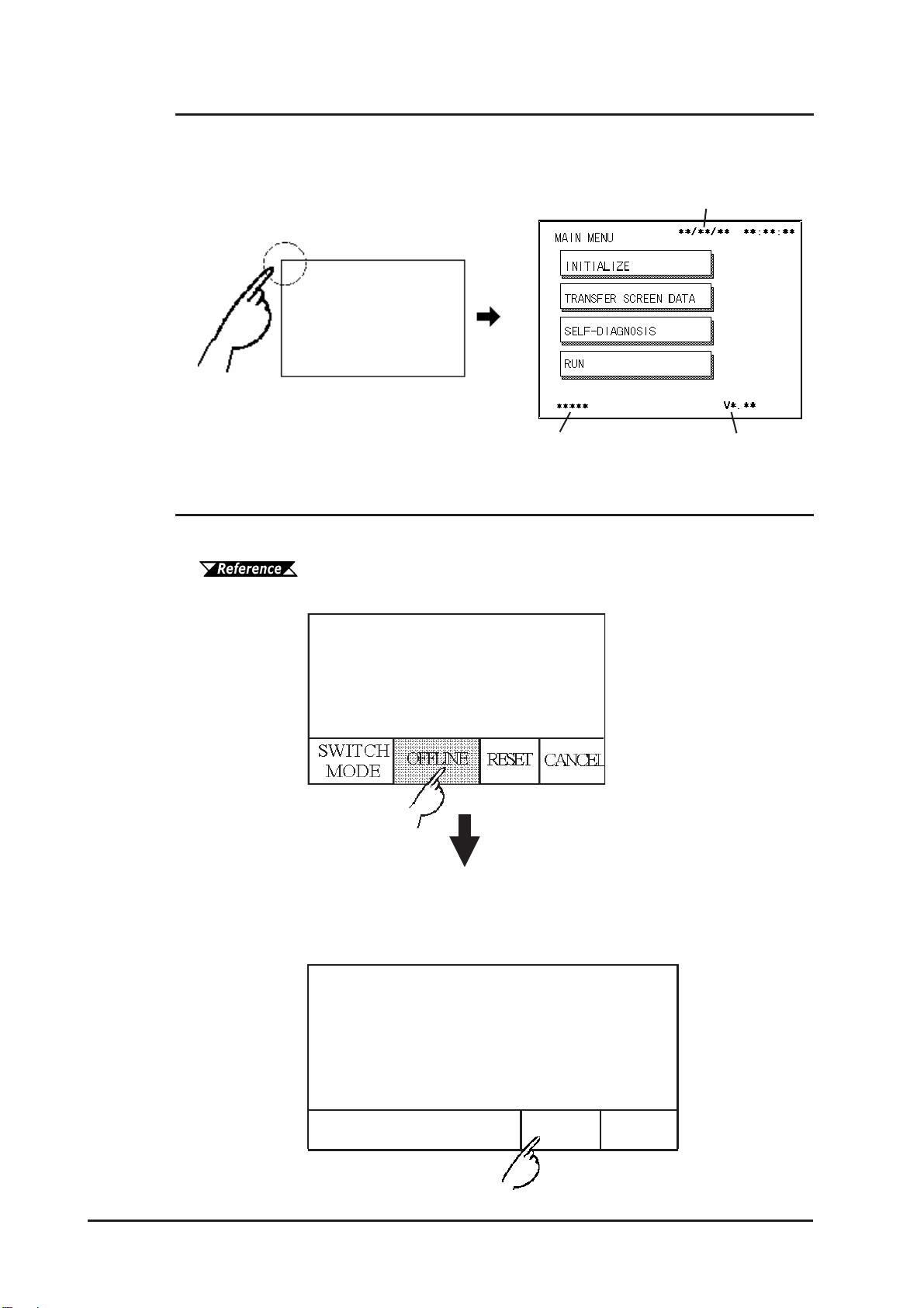
Chapter 5 – OFFLINE Mode
5.1.1 After Plugging in the Power Cord
To enter
OFFLINE mode, touch the top-left corner of the screen within 10 seconds
after connecting the LT unit’s power cord.
Current Date/Time
Protocol Name
Protocol Version
5.1.2 From the Menu Bar
From the LT unit’s menu bar, touch OFFLINE, and the Main Menu appears.
T o call up the Menu Bar, see Section 6.4.3 – SET UP TOUCH PANEL.”
Entering OFFLINE mode will reset the LT unit’s I/O. After confirming that this
will not cause any problems, touch YES.
Entering OFFLINE mode will
reset the LT unit’s I/O.
YES NO
5–2 LT Series User Manual
Page 80
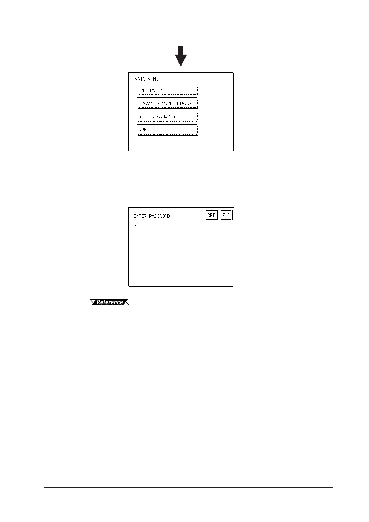
Chapter 5 – OFFLINE Mode
Enter the Password, then touch SET to enter OFFLINE mode.
If you try to enter a Password in the INITIALIZE | SET UP SYSTEM area before
entering OFFLINE mode, the following screen appears:
For more information about Passwords, see Section 6.3.1 – “SYS-
TEM SETUP.
For information about Entering Password Numbers, see
Section 5.3 – “INITIALIZATION.”
”
5–3LT Series User Manual
Page 81
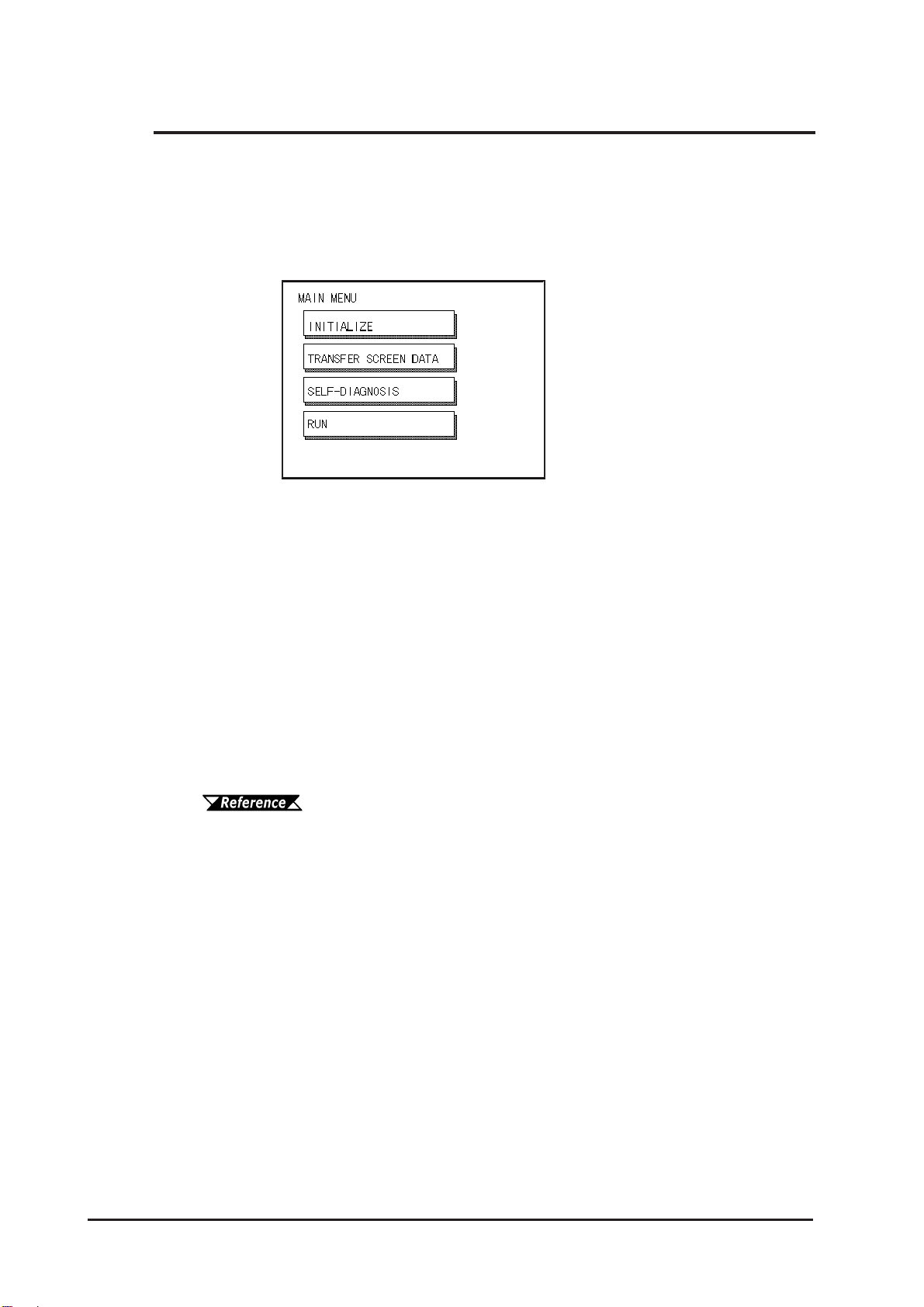
Chapter 5 – OFFLINE Mode
5.2 OFFLINE Mode - Main Menu
The Main Menu contains the following menu items: INITIALIZE, TRANSFER
SCREEN DATA,
The settings for each menu item, below, must match the corresponding external
device, for the LT to communicate properly.
Entering OFFLINE mode calls up the following screen.
SELF-DIAGNOSIS, and RUN.
Select the desired menu item by touching the corresponding option.
Each Main Menu item is used as follows:
INITIALIZE
Setup items control the LT unit.
SCREEN DATA TRANSFER
Transfers screen data between the LT Editor/C-Package and the LT.
SELF-DIAGNOSIS
Checks to see if there are any problems with the LT System or Interface (I/F).
RUN
Starts the LT operation.
For more information about INITIALIZE, see Chapter 6 –
“Initializing the LT”.
For more information about TRANSFER SCREEN DATA, refer to the
LT Editor Operation Manual – Screen Creation Guide (included
with the LT Editor software) and the GP-PRO/PBIII Operation
Manual (included with the C-Package software).
For more information about the SELF-DIAGNOSIS and RUN features,
see Chapter 7 – “LT Run Mode and Errors.”
5–4 LT Series User Manual
Page 82
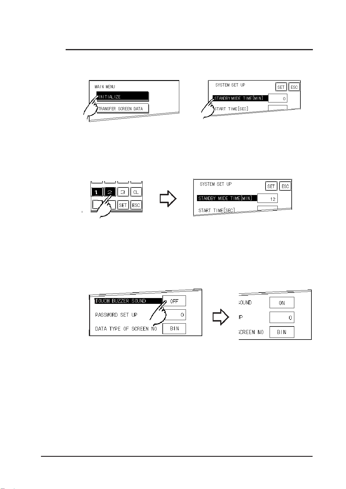
Chapter 5 – OFFLINE Mode
5.3 INITIALIZATION
Selecting Menu and Setting Items
Touch a menu item to select that menu; touch a setting item to select its input field.
Entering Numbers
After selecting an input field, touch the numeric touch keys located at the bottom
of the screen to enter the value of the selected item. After entering each input
field’s numeric value, touch the [SET] key to register the value.
Selecting Setup Conditions
After selecting a menu item, touch the setting option to highlight the item, and
touch the setting area to set the condition for that item.
In this example, touching the ON/OFF area toggles the TOUCH BUZZER SOUND
setting, which is set to OFF, and then switched to ON.
5–5LT Series User Manual
Page 83
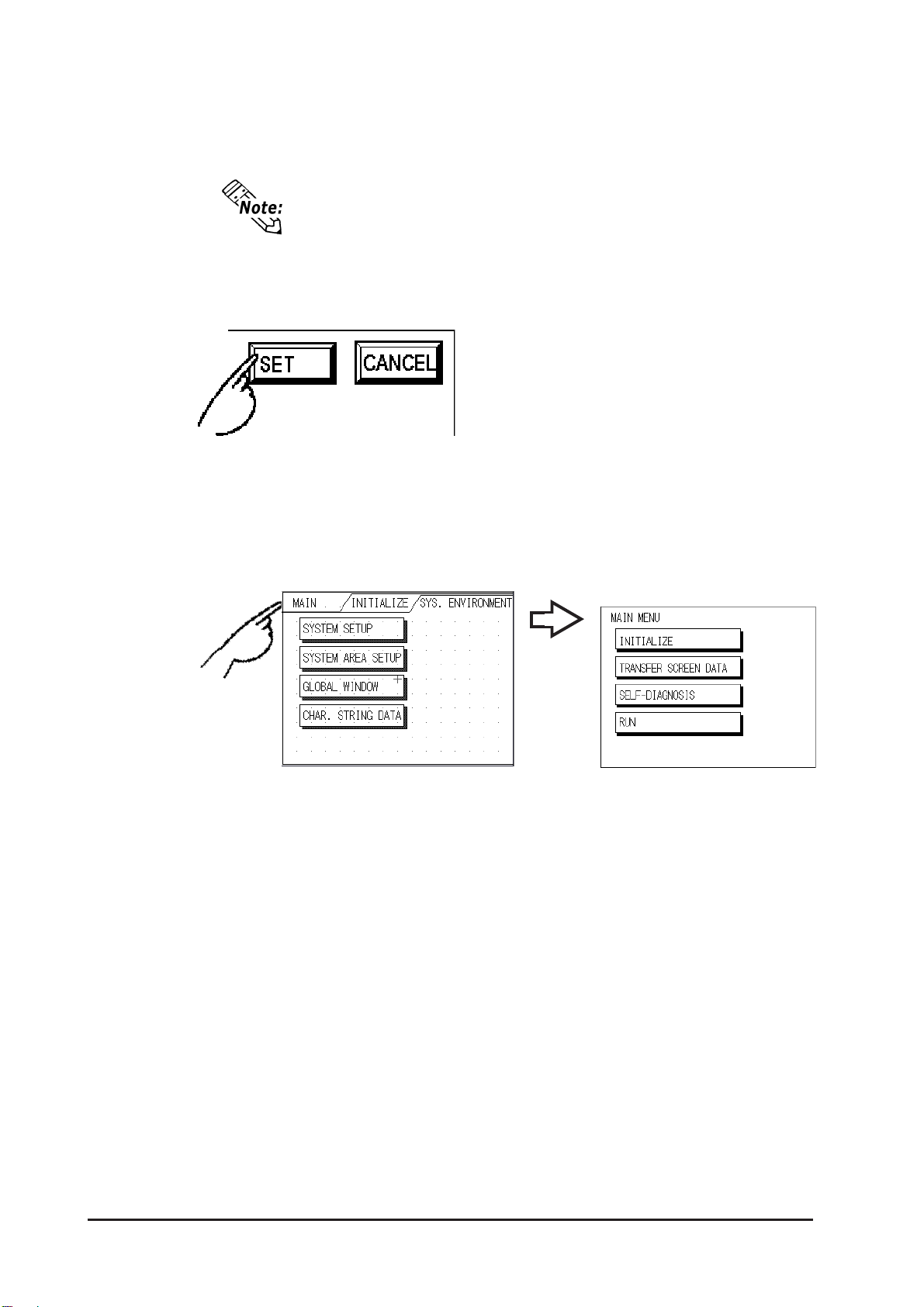
Chapter 5 – OFFLINE Mode
After Entering All Setting Data
Touch the top-left [SET] key to write the setup data to the Internal FEPROM.
After entering the Setup data, do NOT touch the screen until
the previous menu reappears. Writing the Setup conditions
to the Internal FEPROM is a process that requires a short
period of time to complete.
Touch [CANCEL] to cancel the setup, exit the screen without saving the changes,
and return to the previous menu.
Returning to a Previous Screen
Touch the tab to call up the desired menu.
For example, to return to the MAIN MENU from the SYS. ENVIRONMENT screen,
touch the MAIN MENU tab.
5–6 LT Series User Manual
Page 84
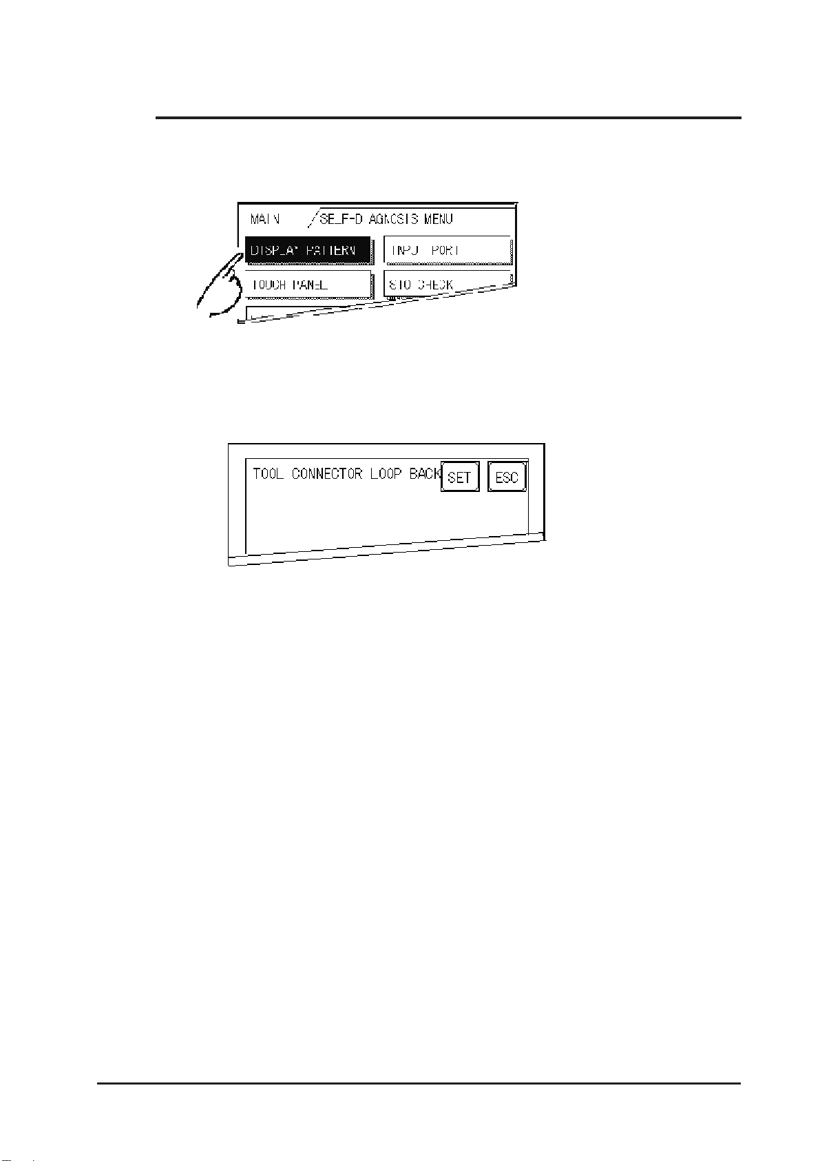
Chapter 5 – OFFLINE Mode
5.4 SELF-DIAGNOSIS
Selecting a Sub-Menu
Touch the desired menu item, and that sub-menu appears.
Using the [SET] and [ESC] Keys
After selecting the Self-Diagnosis item, the [SET] and [ESC] keys may appear at
different times at the top of the screen.
♦♦
♦ [SET] Key
♦♦
When the [SET] key is touched, the Self-Diagnosis test begins.
♦♦
♦ [ESC] Key
♦♦
When the [ESC] key is touched, the Self-Diagnosis test is cancelled, and the
SELF-DIAGNOSIS menu returns.
5–7LT Series User Manual
Page 85
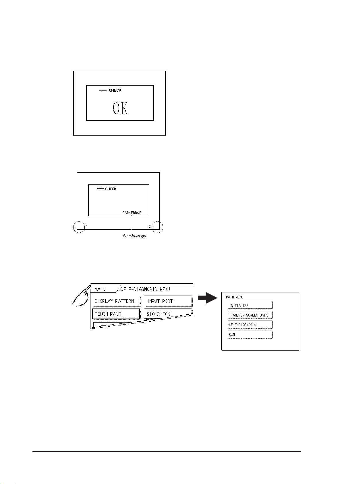
Chapter 5 – OFFLINE Mode
Returning to the SELF-DIAGNOSIS Menu
After performing the Self-Diagnosis check, OK is displayed. Touch once anywhere on the display screen to return to the SELF-DIAGNOSIS MENU.
If an Error Message displays, press the bottom-left corners of the panel [1], and
then touch the bottom-right corner of the panel [2] to return to the SELF-DIAGNO-
SIS MENU
.
Returning to the Main Menu
Touch the MAIN tab in the top-left corner of the SELF-DIAGNOSIS menu to return
to the MAIN MENU.
5–8 LT Series User Manual
Page 86

1. Initialization Screen
2. Initialization Items
3. SYSTEM ENVIRONMENT
SETUP
4. SET UP I/O
Chapter
6 Initializing the LT
6.1 Initialization Screen
To change your LT unit’s general operation settings, use the LT unit’s OFFLINE
mode to access the items in the MAIN MENU | INITIALIZE option.
When you transfer your LT Editor/C-Package’s system file*1,
the LT operates using that file’s data. If the LT System file is
correctly set up and transferred, then setting up the INITIALIZE settings is unnecessary.
For more information about LT System files, refer to the LT Editor
Operation Manual – Screen Creation Guide (included with the LT
Editor software) and the GP-PRO/PBIII Operation Manual (included
with the C-Package software).
5. OPERA TION ENVIRONMENT SETUP
6. INITIALIZE INTERNAL MEMORY
7. SET UP TIME
8. SET UP SCREEN
9. FONT SETTING
1 The information contained in the LT Editor/C-Package’s system file is set by the
software's "System Setup".
6–1LT Series User Manual
Page 87
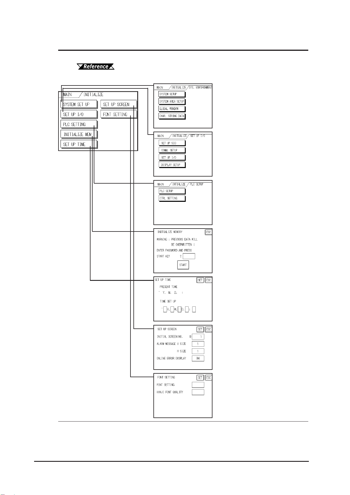
Chapter 6 – Initializing the LT
6.2 Initialization Items
The contents of the Initialize menu’s submenus (below) are explained in this Chapter.
To learn about screen operations and numeric input, see
Chapter 5 – “OFFLINE Mode.”
SYS. ENVIRONMENT
SYSTEM SETUP
SYSTEM AREA SETUP
GLOBAL WINDOW
*1
*1
CHAR. STRING DATA
SET UP I/O
SET UP SIO
COMM. SETUP
*2
*2
SET UP I/O
DISPLAY SETUP
PLC SETUP
PLC SETUP
STATION SETUP (n:1)
*3
*3
CUSTOMIZE SETUP (n:1)
CTRL SETTING
*3
INITIALIZE MEMORY
SET UP TIME
SET UP SCREEN
FONT SETTING
6–2
1 This feature is not available.
2 Setup item invalid with, and not supported by, Type A1, Type A2, Type B, or Type B+.
3 Setup item invalid with, and not supported by, Type A1, Type A2, Type B, or Type B+.
Also the setting screen will vary depending on the [Device/PLC Type (Serial I/F)]
selected via LT Editor/C-Package’s [Project/New] menu.
LT Series User Manual
Page 88
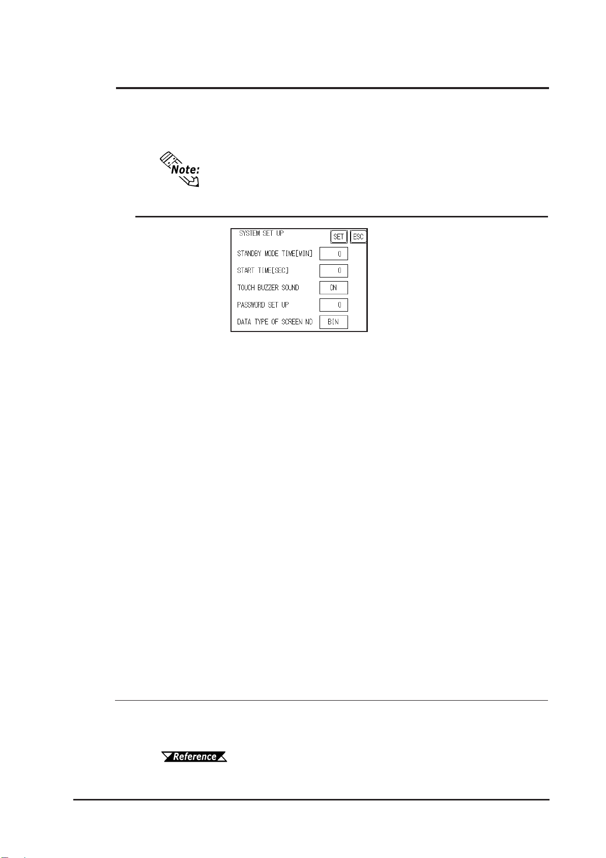
Chapter 6 – Initializing the LT
6.3 SYSTEM ENVIRONMENT SETUP
LT environment adjustments are made within the setup screens contained in the
SYSTEM ENVIRONMENT SETUP menu. Screens include the SYSTEM SETUP
and CHARACTER STRING DATA SETUP.
The SYSTEM AREA SETUP and GLOBAL WINDOW SETUP
features are not available.
6.3.1 SYSTEM SETUP
STAND-BY MODE TIME (0–255)
To protect the LT unit’s display screen, a screen saver function automatically turns
the unit’s backlight(s) OFF when no operations have occurred within a specified
period of time. No screen saver will be used when “0” is entered in this field.
When the SYSTEM DAT A AREA’s SCREEN DISPLAY OFF*1 data is set to 0000h,
the LT unit’s current display data will clear if the following operations are not
performed within the user’s specified period of time:
• Change Screen
• Touch Screen
• Alarm Display
START TIME (0–255)
Use this setting item to specify the LT unit’s startup time — or to adjust the
powering-up sequence — so that the LT starts up after the external devices start.
TOUCH BUZZER SOUND
Use this feature to indicate with a buzzing sound that the LT has been touched.
PASSWORD SETUP
The password setting item is used when the LT switches to the Initialize Memory
or Initialize (OFFLINE mode) screens. The password — a number between 0 and
9999 — is a security feature within the OFFLINE mode, to protect the LT settings.
If you do not wish to use this feature, enter the default value, “0.”
1 When using the Direct Access format, the object address becomes LS0009. When
using the Memory Link format, the object address becomes +12. (Only when all items
are set within the System Data Area.)
LT Series User Manual
LT Editor Device Connection Manual (included with the LT Editor software), GP-PRO/PBIII Device/PLC Connection Manual
(included with the C-Package software)
6–3
Page 89
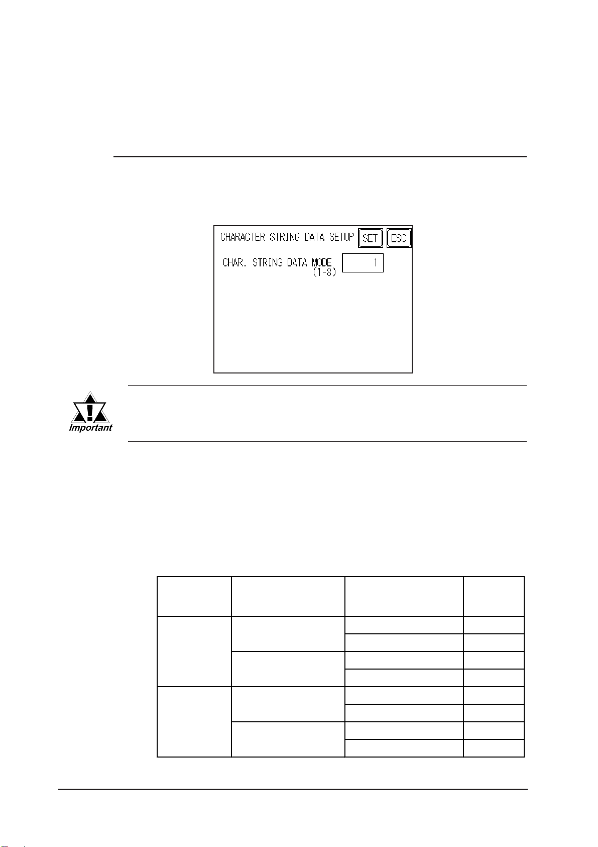
Chapter 6 – Initializing the LT
DATA TYPE OF SCREEN NO.
This setting specifies whether BIN or BCD format numbers are used when making
screen changes.
6.3.2 CHARACTER STRING DATA SETUP
Character String Data ordering varies, depending on the manufacturer of the
external device. Set up the Character String Data order to match that of the corresponding external device.
Set the CHARACTER STRING DATA MODE to match that of the corresponding external devices. Only the external devices — and not their
internal device addresses or Tag settings — are available for setup.
CHAR. STRING DATA MODE
Set up the CHARACTER STRING DATA MODE that corresponds to that of your
external device, as specified in the following table.
(I) Data Device Storage Order
(II) Byte Storage Order (LH/HL), using single words
(III) Word Storage Order (LH/HL), using double words
CHARACTER STRING DATA MODE (1–8) List
(I) Data Device
Storage
Order
Storage from
Start Data
Storage from
End Data
(II) Byte Storage
Order (LH/HL),
using single words
LH order
HL order
LH order
HL order
(III) Word Storage Order
(LH/HL), using
double words
LH order
HL order
LH order
HL order
LH order
HL order
LH order
HL order
Character
String Data
Mode
4
2
5
1
6
7
8
3
6–4
LT Series User Manual
Page 90
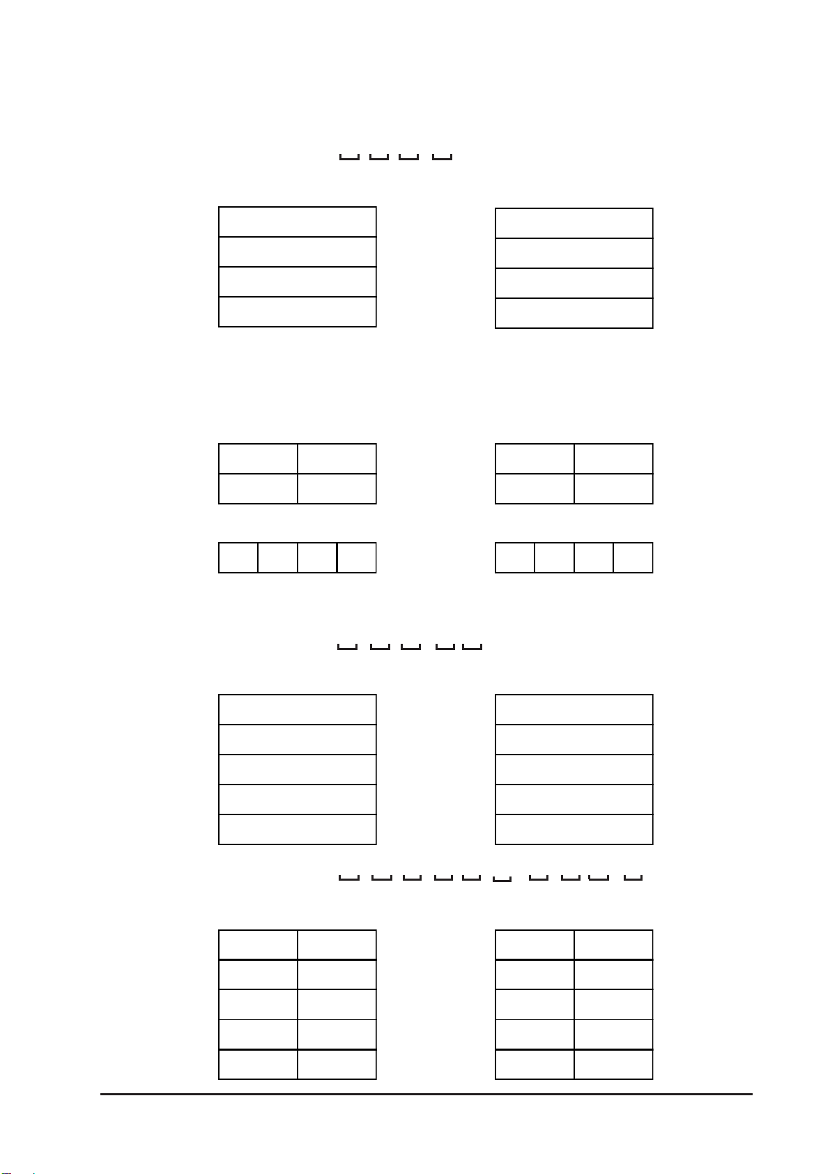
Chapter 6 – Initializing the LT
I. Data Device Storage Order
Example characters:A B C D E F G H
cde f
• Storage from Start Data • Storage from End Data
c
D100
f
D100
d
e
f
D101
D102
D103
e
d
c
II. Byte Storage Order (LH/HL), using Single Words
Example characters:A B C D
cdef
• 16-bit Device LH Order • 16-bit Device HL Order
d c
f e
• 32-bit Device LH Order • 32-bit Device HL Order
d c f e c d e f
D100
D101
D100 D100
c d
e f
III. Word Storage Order (LH/HL), using Double Words
Example characters:A B C D E F G H I J
D101
D102
D103
D100
D101
cde fg
• 16-bit Device LH Order • 16-bit Device HL Order
d
c
f
e
g
Example characters:A B C D E F G H I J K L M N O P Q R S T
cdefgh ijkl
• 32-bit Device LH Order • 32-bit Device HL Order
d c
f e
h g
j i
D100
D101
D102
D103
D104
D100
D101
D102
D103
c
d
e
f
g
c d
e f
g h
i j
D100
D101
D102
D103
D104
D100
D101
D102
D103
LT Series User Manual
l k
D104
k l
D104
6–5
Page 91

Chapter 6 – Initializing the LT
Relationship between the internal device address and external devices,
when using the Write Character Value operation.
16-bit Devices
The LT stores the character string in one internal Device, in groups of two, starting
with the first pair of characters.
When nine characters make up a string, they are arranged as follows:
1 2 3 4 5 6 7 8 9 Null
When the characters do not divide evenly by two, NULL is
added to the last character to make up the final pair and complete the string.
32-bit Devices
The LT stores the character string in one internal device address, in groups of four,
starting with the first group of characters.
When there are nine characters, they are arranged as follows:
1 2 3 4 5 6 7 8 9 Null
When the characters do not divide evenly by four, NULL is
added to the last character to make up the final group and
complete the string.
6–6
LT Series User Manual
Page 92
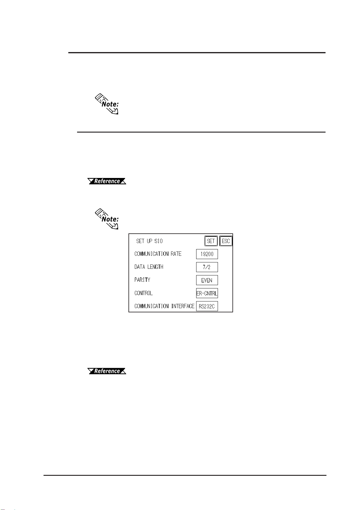
Chapter 6 – Initializing the LT
6.4 SET UP I/O
This section describes the communication setup and the configuration for any
peripheral equipment. The SET UP I/O menu includes the SET UP SIO, COMMU-
NICATION SETUP
6.4.1 SET UP SIO
This screen controls the settings related to communication with the external
devices. The settings will vary, depending on the external device.
Be sure to match the LT unit’s SIO settings (below) with the SIO settings of the
external device.
, SET UP TOUCH PANEL, and DISPLA Y SETUP screens.
The SET UP SIO and COMMUNICATION SETUP setting
items are invalid with and are not supported by Type A1, Type
A2, Type B, or Type B+ units.
LT Editor Device Connection Manual (included with the LT Editor
software), GP-PRO/PBIII Device/PLC Connection Manual (included with the C-Package software)
The following settings are not available with Type A1, Type
A2, Type B, or Type B+ units.
COMMUNICATION RATE
The COMMUNICATION RATE (baud rate) is the data communication speed,
measured in bits per second (bps), between the LT and the external devices.
Depending on the rate selected, you may not be able to use certain external devices.
LT Editor Device Connection Manual (included with the LT Editor
software), GP-PRO/PBIII Device/PLC Connection Manual (included with the C-Package software)
DATA LENGTH / STOP BIT
For data communication, use the following settings:
• DATA LENGTH: 7 or 8 bits
• STOP BIT: 1 or 2 bits
PARITY
Use this setting to specify whether an ODD or EVEN number parity check, or
NONE at all, will take place during communication.
LT Series User Manual
6–7
Page 93
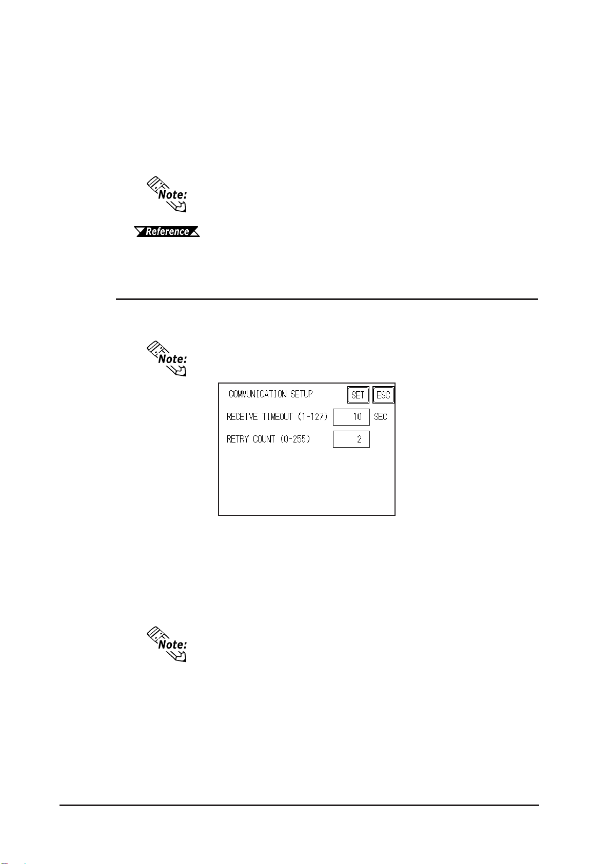
Chapter 6 – Initializing the LT
CONTROL
The Data Flow CONTROL setting prevents the overflow of data transmitted and
received. Select either X-CNTRL or ER-CONTRL.
COMMUNICATION FORMAT
Use the RS-232C, the RS-422 (4-line), or the RS-422 (2-line) for the Communication Format setting.
When using an RS-422 cable and the Memory Link format,
be sure to select the 4-line option.
LT Editor Device Connection Manual (included with the LT Editor
software), GP-PRO/PBIII Device/PLC Connection Manual (included with the C-Package software)
6.4.2 COMMUNICATION SETUP
This section explains how to use the Retry command to deal with errors, including
those that occur during communication between the LT and external devices.
This setting is disabled on the Type A1, Type A2, Type B and
Type B+ units
RECEIVE TIMEOUT
Use a numeric value to set a period of time in which the LT can receive data from
the external device. When the cable is not connected, data communication will
Timeout after one second, regardless of this setting’s value.
The default value for the RECEIVE TIMEOUT setting is 10 seconds.
When the RECEIVE TIMEOUT value is set to 30 seconds or
more and the occurrence of an external communication error
has not yet cleared, transferring screen data files may result
in an error message appearing on your PC.
6–8
RETRY COUNT
Use this setting item to designate the number of times the LT tries to send data to
the external device when an external communication error occurs. After the LT
unit’s specified number of attempts has failed to send data to the external device,
an error message will appear on the LT.
The default value for the Retry Count setting is “2.”
LT Series User Manual
Page 94
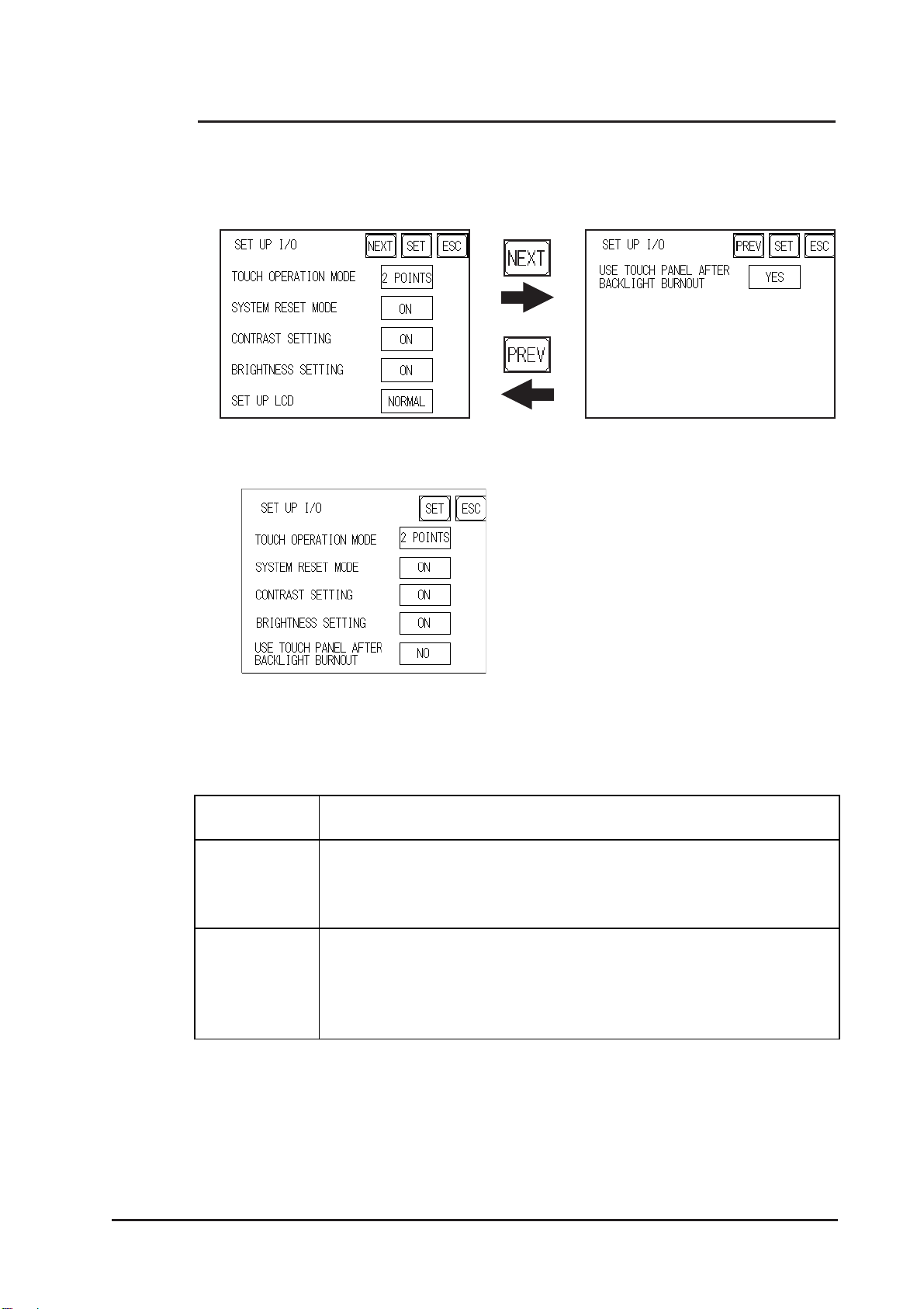
Chapter 6 – Initializing the LT
6.4.3 SET UP TOUCH PANEL
This screen is where you can set up the touch panel’s Touch Operation and System
Reset modes, and adjust the Display settings.
When using a monochrome model:
When using a color model:
TOUCH OPERATION MODE
Designates either One Point, Two Points, or No Slide.
1 Point Touch
2 Point Touch
No Slide
Designates that the touch panel accepts only 1 point touch input. As
soon as touch screen contact is released, touch input is cancelled.
Designates that the touch panel accepts up to 2 points of touch
input. If 3 or more points are touched simultaneously, input is not
accepted and touch input is not cancelled. In a single switch, up to 2
points can be touched.
Designates that the touch panel accepts only 1 point touch input. If
2 or more points are touched simultaneously, input is not accepted
and touch input is not cancelled.
Input is cancelled if the touch is moved (slides) outside the current
"active" area.
LT Series User Manual
6–9
Page 95
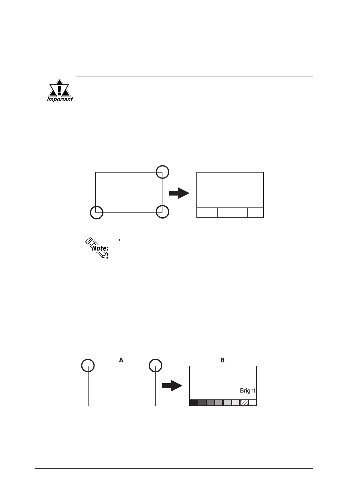
Chapter 6 – Initializing the LT
3
SYSTEM RESET MODE
This setting allows the user to enable or disable the System Reset menu bar. When
set to YES, the menu bar will display.
You can perform SYSTEM RESET regardless of whether the LT unit is
operating in RUN mode or in OFFLINE mode.
To Display the Menu Bar
To enter the SYSTEM RESET mode, press the bottom-right corner of the screen
(position 1, below), and then touch the top-right and bottom-left corners (positions 2 and 3).
To activate Reset, touch the RESET button; to change to OFFLINE Mode, touch
OFFLINE.
2
3
• The menu bar will not display while the LT is starting up.
• Entering SYSTEM RESET is possible even when the external device and the LT are communicating.
1
Switch Mode OFFLINE RESET CANCEL
CONTRAST SETTING
When CONTRAST SETTING is set to ON, you can adjust the contrast by touching
the LT unit’s screen. To adjust the Contrast mode, press the screen’s top-left
corner (screen A, position 1, below), and then touch the top-right corner (position
2). When the contrast adjustment screen (B) appears, touch to select the desired
level of brightness, and the screen’s contrast will adjust according to your changes.
AB
21
Dark
6–10
Bright
2
LT Series User Manual
Page 96
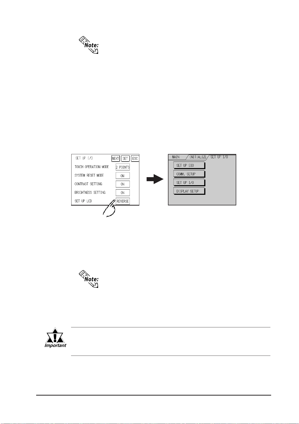
Chapter 6 – Initializing the LT
• To exit the CONTRAST SETTING mode, touch anywhere
above the Contrast Setting bar.
• You cannot enter the CONTRAST SETTING mode while
waiting for LT to start up.
• CONTRAST SETTING adjustments (LT and external de-
vices) can be made during RUN mode.
BRIGHTNESS SETTING
The brightness control function is unavailable and the setting is invalid in the LT
unit.
SET UP LCD
This setting reverses the colors of the LT unit’s display screen and characters.
To reverse the screen’s display, touch SET UP LCD on the SET UP I/O screen to
change the setting from NORMAL to REVERSE, and then touch the SET key .
The display color reverses and the SET UP I/O menu reappears.
USE TOUCH PANEL AFTER BACKLIGHT BURNOUT
Access this setup screen by touching [NEXT]. This setting allows the user to
enable [YES] or disable [NO] the touch operation when the backlight burns out.
Setting this item to [NO] prevents the LT from sending input signals to the external devices.
When the Backlight Burns Out:
• The Status LED’s orange light will turn ON.
1
• The System Data Area’s Status bit 10*
• If the SYSTEM RESET item is set to ON, only SYSTEM
RESET can still be performed by touch operation.
• If the LT is in OFFLINE mode, the touch-panel operation
will become enabled, regardless of the settings.
Normally, the unit detects backlight burnout by monitoring the current;
however, depending on the problem with the backlight, the unit may fail
to detect this condition.
will turn ON.
LT Series User Manual
6–11
Page 97
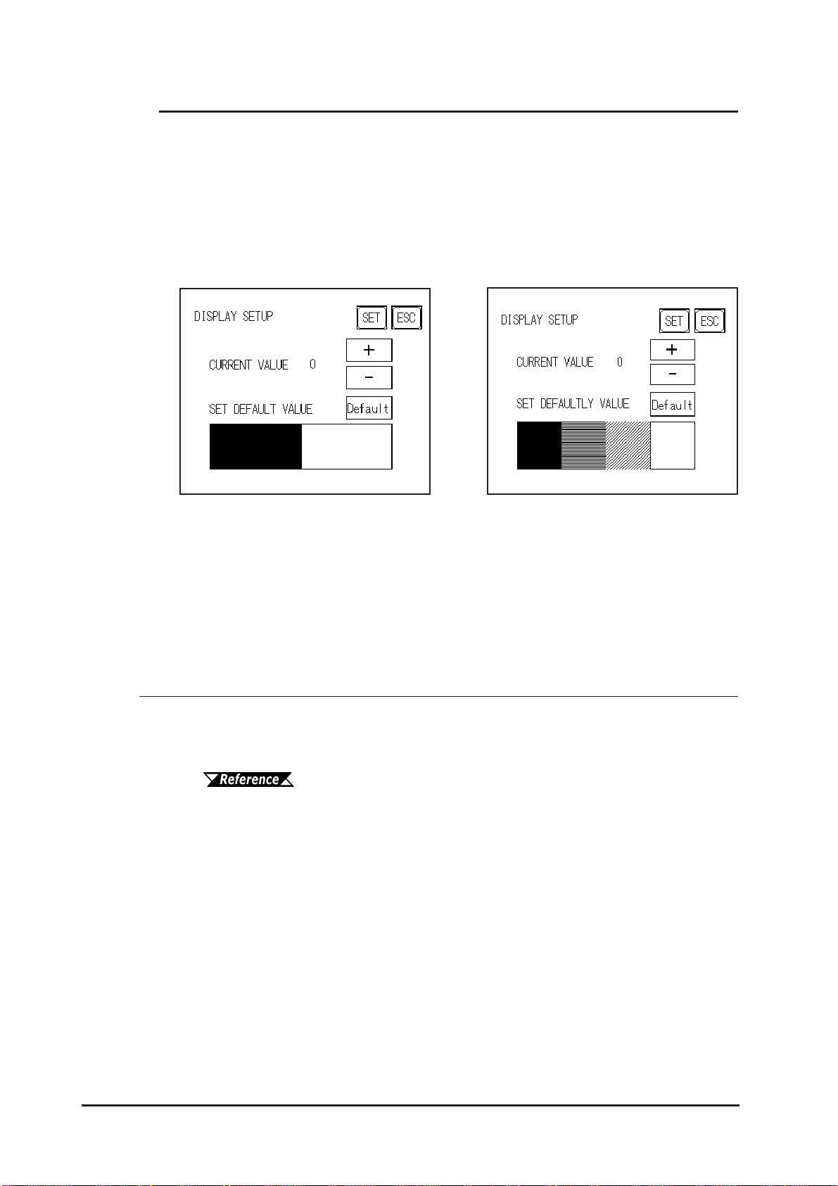
Chapter 6 – Initializing the LT
6.4.4 DISPLAY SETUP
The LT unit’s screen may flicker , or the LCD’s surface may appear to have shadows on extended display lines. This effect may be more pronounced when the LT
unit’s ambient temperature is high, and its current level of brightness is set to low.
This phenomenon, however, is a common attribute of LCDs and is not a defect.
T o solve this problem, use the Display Setup screen to adjust the LT unit’s brightness.
When using a monochrome model: When using a color model:
CURRENT VALUE
Touch [+] or [-] to adjust the levels of brightness (18 levels of [+] and two levels
of [-] brightness). You can check the brightness level in the preview field at the
bottom of the screen. The default value of brightness is “0.”
SET DEFAULT VALUE
If you touch Default, the setting returns to “0.”
1 When using the Direct Access format, the object address becomes Bit +6. When
using the Memory Link format, the object address becomes +11. (Only when all items
are set within the System Data Area.)
LT Editor Device Connection Manual (included with the LT Editor software), GP-PRO/PBIII Device/PLC Connection Manual
(included with the C-Package software)
6–12
LT Series User Manual
Page 98
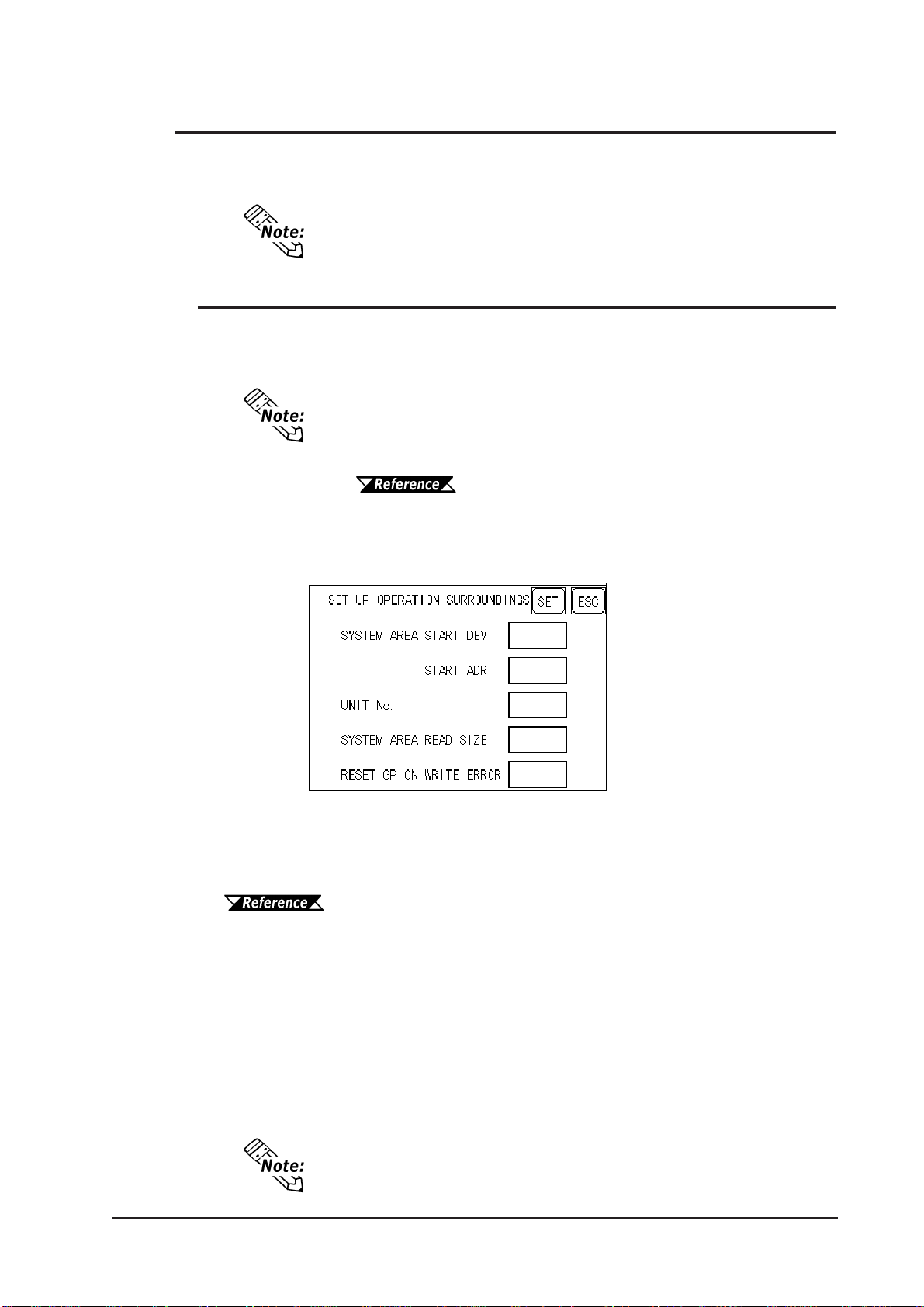
Chapter 6 – Initializing the LT
6.5 OPERATION ENVIRONMENT SETUP
Set up the external device’s System Area and the Unit Number in this screen. This
section pertains to external devices that use the Direct Access format.
When the LT Editor/C-Package’s Simulation feature is used,
the
OPERATION SURROUNDINGS menu cannot be used.
6.5.1 SET UP OPERATION ENVIRONMENT
Use this setup screen to enter the external device’s System Data Area and the Unit
Number settings.
• Type A1, Type A2, Type B and Type B+ do not have this
setting.
• The screens that appear depend on the external device
that you selected in the LT Editor/C-Package.
LT Editor Device Connection Manual (included
with the LT Editor software), GP-PRO/PBIII De-
vice/PLC Connection Manual (included with the
C-Package software)
SYSTEM AREA START (DEV / ADR)
Use this item to set up the System Data Area’s Start Address. User-specified
Device Addresses will differ , depending on the type of external device used.
UNIT NO.
Enter the UNIT number of the external device. Be sure that it matches the unit number
of the external device.
SYSTEM AREA READ SIZE
When using a Block Display Trend Graph, set up the Reading Area Size (in word
units) to match the Trend Graph’s data size.
LT Series User Manual
LT Editor Device Connection Manual (included with the LT Editor
software), GP-PRO/PBIII Device/PLC Connection Manual (in-
cluded with the C-Package software)
If you are not using the Reading Area, leave the default val-
ues that are set to “0” intact, to allow high-speed data com-
munication.
6–13
Page 99
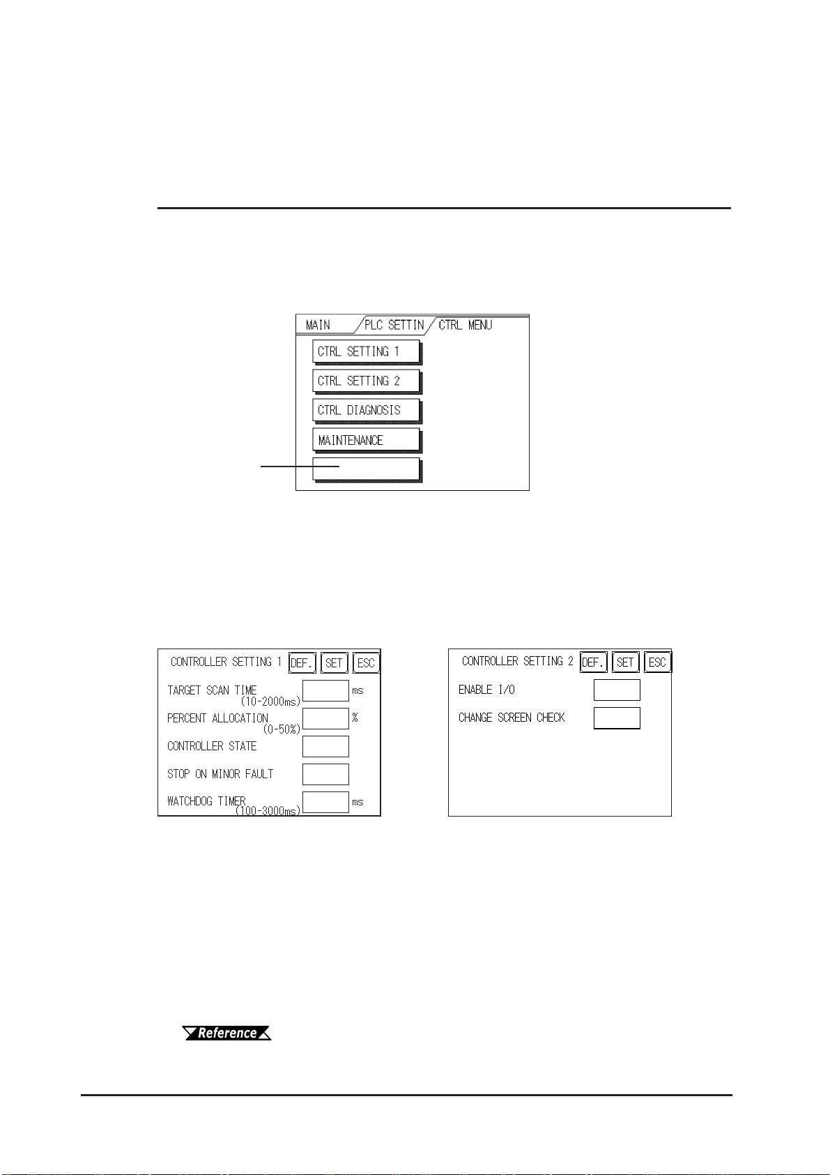
Chapter 6 – Initializing the LT
RESET LT ON DATA WRITE ERROR
This setting item allows you to reset the LT, from the error display, when the
Write error occurs.
6.5.2 CONTROLLER SETTINGS
This section describes the Controller setting items. The CTRL MENU includes
the CTRL SETTING, CTRL DIAGNOSIS, and I/O DRIVER setup screens.
For a description of the CTRL DIAGNOSIS and I/O DRIVER setting items, see
the references cited at the end of this section.
User-selected I/O
Driver’s name is
displayed here
CTRL SETTING
Information set via LT Logic Program Editor/C-Package or Controller Settings is
stored in the LT unit’s nonvolatile memory. Although each item in the Controller
Settings screen has a default setting, each should be set to match your application.
Controller Setting 1 Controller Setting 2
CONTROLLER SETTING 1
TARGET SCAN TIME
Use Target Scan Time to set the time periods for the Controller and the Display
operation time functions. The setting range for Target Scan Time is between 10
and 2000 ms.
6–14
The Controller Operation Time function sets the time it takes to execute the I/O
reading, Logic Program, and I/O writing. When Target Scan is set, the maximum
time allocated to the Controller Operation Time function is 50%.
LT Editor Operation Manual – Logic Programming Guide (included
with the LT Editor software), Pro-Control Editor User Manual (included with the C-Package software)
LT Series User Manual
Page 100
Chapter 6 – Initializing the LT
PERCENT ALLOCATION
Use Percent Allocation to set the ratio of Controller Operation Time Function in
Target Scan Time. The setting range for Percent Allocation is between 0 and 50%.
When Percent Allocation is set, Target Scan is disabled.
LT Editor Operation Manual – Logic Programming Guide (included
with the LT Editor software), Pro-Control Editor User Manual (included with the C-Package software)
CONTROLLER STATE
This item sets the Operation Mode — Default, Run, or Stop — when the power is
ON.
The Controller State setting is valid only when the RUN/STOP switch on the back
of LT is set to Run. When the switch is set to Stop, the Operation Mode will
always be Stop, regardless of this setting’s value.
STOP ON MINOR FAULT
This item either stops the Controller or executes a logic program when a minor
fault occurs. If you wish operation to continue after a fault occurs, set this switch
to Continue; if you wish to stop operation, set it to Stop.
LT Editor Online Help, Pro-Control Editor Online Help
WATCHDOG TIMER
Sets the Watch Dog Timer (WDT) for the Controller Operation Time and the LT
Operation Time functions to between 100 and 3000 ms. Input the value in units of
100 ms. Inputting “0” is invalid.
CONTROLLER SETTING 2
CHANGE SCREEN CHECK
After #Screen is used to perform the screen change, the #Screen setting value is
reset to “0”. Using the ON (initial) setting will clear the #Screen value to “0”.
LT Editor Operation Manual – Logic Programming Guide (included
with the LT Editor), Pro-Control Editor User Manual (included with
the C-Package software)
CTRL DIAGNOSIS
Section 7.3.3 – “List of Controller Self-Diagnostics Items”
I/O DRIVER
The supported driver type depends on the LT type. Types A1 and A2 support the
DIO driver, and types B, B+ and C support the Flex Network Driver. The logic
program that configures each I/O driver will be downloaded.
LT Series User Manual
LT Editor Operation Manual – Logic Programming Guide (included
with the LT Editor), Pro-Control Editor Operation Manual (included
with the C-Package software)
6–15
 Loading...