

Page 1

+\EULG7HUPLQDO%ORFN
+DUGZDUH0DQXDO
Page 2

Preface
Thank you for purchasing Pro-face’s the Hybrid Terminal Block.
The Hybrid T erminal Block (Hereafter referred to as the "HTB") network interface module with built-in Inputs/Ou tputs is
small in size. Its modularity , by adding I/O expansio ns, can be used to optimize an ap plication by providing the necessary
number of I/Os.
The HTB connects directly to a CANopen field bus.
The HTB accepts up to 7 EX modules.
Before operating your HTB, be sure to read this manual to familiarize yourself with the HTB's operation procedures and
features.
NOTICE
1. Copying this manual's contents, either in whole or in part, is prohibited without the express permission of Digital
Electronics Corporation, Japan.
2. The information contained in this manual is subject to change without notice.
3. If you should find any errors or omissions in this document, please contact Digital Electronics Corporation to
report your findings.
4. Regardless of Clause 3 above, Digital Electronics Corporation shall not be held responsible for any damages,
losses or third-party damages resulting from the use of this product.
© 2008 Copyright Digital Electronics Corporation. All rights reserved.
Product names used in this manual are the trademarks / registere d trademarks of their respective owners.
1
Page 3
Essential Safety Precautions
All safety-related procedures stated in this document must be followed to operate the HTB correctly and safely. Be sure to
read this and any related documents thoroughly to understand the correct operation and functions of the HTB.
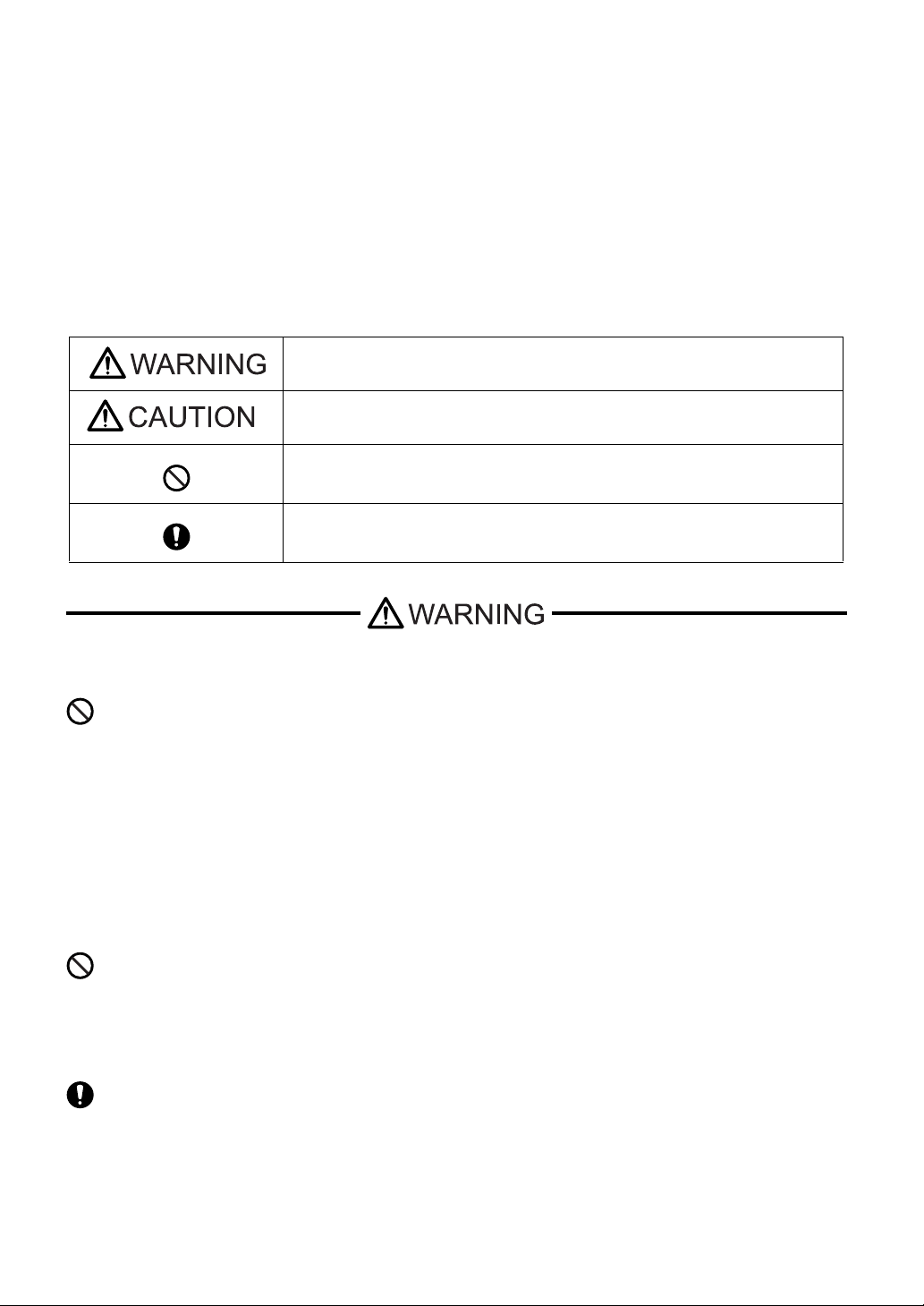
Safety Icons
Throughout this manual, these icons provide essential safety information for HTB operation procedures requiring special
attention. These icons indicate the following levels of danger:
Indicates situations where severe bodily injury, death or major equipment damage
can occur.
Indicates situations where slight bodily injury or minor equipment damage can
occur.
Indicates actions or procedures that should NOT be performed.
Indicates actions or procedures that MUST be performed to ensure correct unit
operation.
DANGER OF ELECTRIC SHOCK AND FIRE
A significant amount of current may be present on each relay output (up to 2A).
There is a risk of current overload resulting in possible shock and/or fire.
• Use appropriately sized cables for the load potential.
• Protect each output with an appropriately sized fuse.
RISK OF UNINTENDED EQUIPMENT OPERATION
Failure to follow this precaution can result in death, serious injury, or equipment damage.
Do not add or remove an expansion module to or from the system before first removing all power. Adding
or removing an expansion module while under power can cause damage to the module and the system
resulting in unexpected operation of inputs and outputs. Depending on the I/O configuration, unintended
equipment operation can occur.
Keep adequate spacing around the island for proper ventilation and to maintain an ambient temperature
between 0°C (32°F) and 55°C (131°F).
Overheating of HTB and/or the I/O expansion modules can result in unexpected operation of inputs and
outputs. Depending on the I/O configuration, unintended equiment operation can occur.
2
Page 4
Do not place heat generating devices such as transformers and supp ly blocks unde r the island.
Heat generating devices in proximity of HTB and I/O expansion modules could result in elevated
temperatures and overheating, and can result in unexpected operation of inputs and outputs. Depending
on the I/O configuration, unintended equipment operation can occur.
Do not exceed the 450mA current limit for HTB and its expansion modules. Exceeding these limits can
result in interruption of power to the I/O. Depending on I/O configuration, unintended equipment operation
may result.
If outputs should fail, outputs may remain on or off. Where personnel and or equipment hazards exist, use
an appropriate hard-wired safety system.
When the power supply voltage is outside of the specified voltage range, one or more outputs may not
operate as expected. Use an appropriate externally-wired safety system to control and monitor the system
voltage and ensure the specified voltage range is maintained.
Turn power off before installing, removing, wiring, or maintaining.
This product is not intended for use in safety critical machine functions. Where personnel and or
equipment hazards exist, use appropriate hard-wired safety interlocks.
Do not disassemble, repair, or modify the modules.
This controller is designed for use with in an enclosure.
Install the modules according to the installation instructions on page 3-2.
Use the sensor power supply only for supplying power to sensors connected to the module.
Use an IEC60127-approved fuse on the power line and output circuit to meet voltage and current
requirements.
®
Recommended fuse: Littlefuse
5x20 mm Slo-Blo® 218 Series.
Unit Disposal
When the product is disposed of , it should be done so according to your country's regulations for similar
types of industrial waste.
3
Page 5
Information Symbols
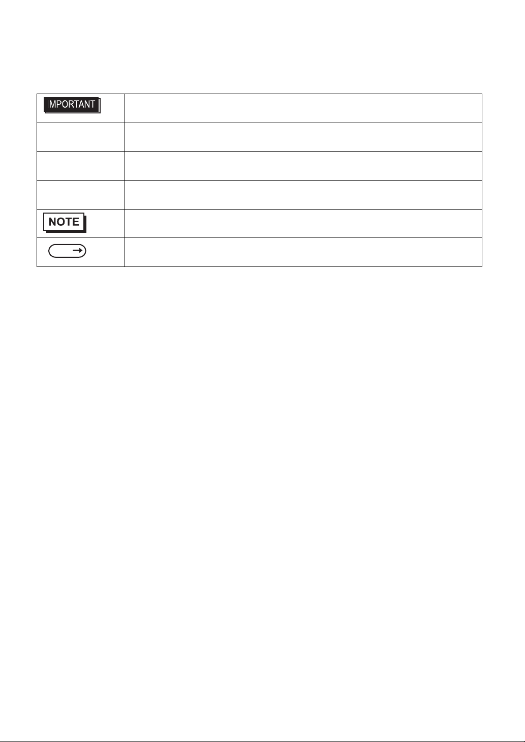
This manual uses the following icons:
Indicates a warning or a product limitation. Be sure to follow the instructions given with
this icon to ensure the safe operation of the HTB.
Screen Editor Indicates the GP-Pro EX software.
PLC Abbreviation for Programmable Logic Controller.
* Indicates useful or importan t supplemental information.
Contains additional or useful information.
SEE
Indicates pages containing related information.
About the Manuals
For the detailed information on HTB, refer to the following manuals.
• Hybrid Terminal Block Hardware Manual (this manual)
• GP-Pro EX Reference Manual "Controlling External I/O by Using HTB"
• Maintenance/Troubleshooting
• GP3000 Series Hardware Manual
• CANopen Master Unit Hardware Manual
• EX Module Hardware Manual
The manuals can be downloaded from Pro-face Home Page.
URL
http://www.pro-face.com/otasuke/
4
Page 6
Package Contents
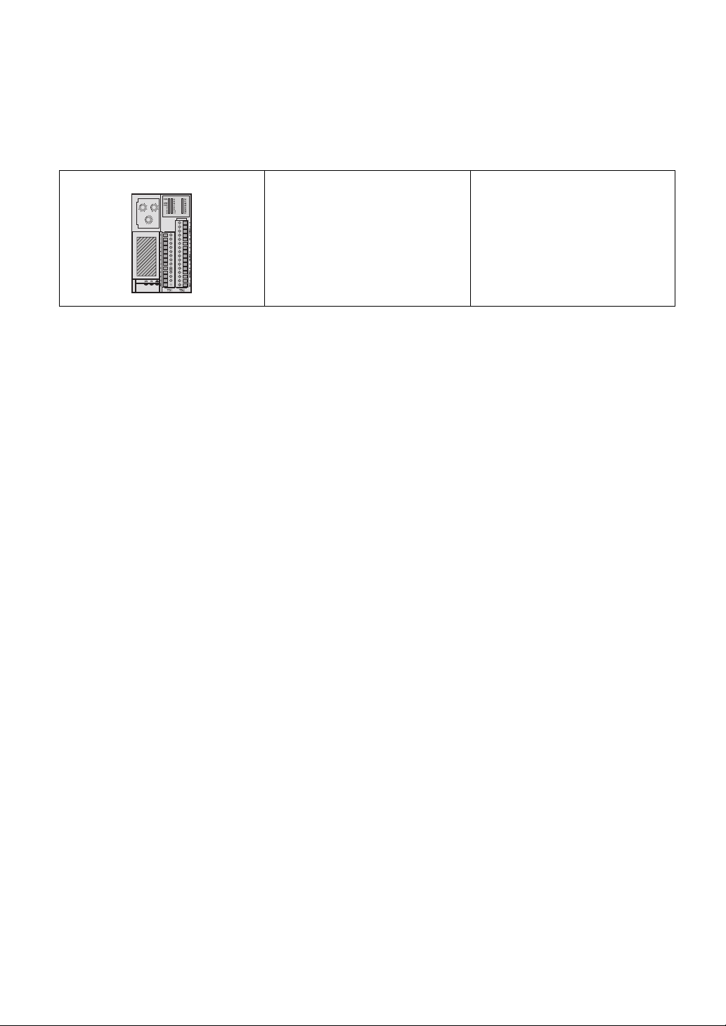
The following items are included in the HTB's package. Before using the HTB, please check that all items listed
here are present.
HTB: 1 • English and Japanese
ADDRESS
NOT
0
0
NOT
2
2
USED
USED
4
4
12
10
6
6
8
8
ONESTENS
0
1
2
3
NOT
4
USED
5
6
9
7
8
BAUD RATE
Installation Guide
• Connector for Input
(1, attached to HTB)
• Connector for Output
(1, attached to HTB)
This unit has been carefully packed, with special attention to quality. However, should you find anything damaged or missing, please contact your local HTB distributor immediately.
5
Page 7

UL/c-UL/CSA Approval
This unit is UL/c-UL/CSA listed product: (UL File No. E210412, CSA File No. 240854)
This product conforms to the following standards:
•UL508
Industrial Control Equipment
•UL1604
Electrical Equipment for Use in Class I and II, Division 2, and Class III Hazardous (classified) Locations
• CSA-C22.2 No.142-M1987
Standard for Process Control Equipment
• CSA-C22.2 No.213-M1987
Non-Incendive Electrical Equipment for Use in Class I, Division 2 Hazardous Locations
Warning - Explosion Hazard - This equipment is suitable for use in Class I, Division 2, Groups A, B, C, D or nonhazardous locations only.
Warning - Explosion Hazard - Substitution of components may impair suitability for Class I, Division 2 compliance.
W arning - Explosion Hazard - Do no t disconnect equipment unless power has been switched off or the area is known to be
nonhazardous.
CE Marking
This unit is CE marked product that conforms to EMC directives, EN55011 Class A and EN61131-2.
6
Page 8

Contents
Preface...................................................................................................................... 1
Essential Safety Precautions.....................................................................................2
Information Symbols..................................................................................................4
About the Manuals ....................................................................................................4
Package Contents..................................................................................................... 5
UL/c-UL/CSA Approval..............................................................................................6
CE Marking................................................................................................................ 6
Chapter 1 Introduction
1.1 About CANopen..............................................................................................1-2
1.1.1 I ntroduction..........................................................................................................1-2
1.1.2 The CANopen Protocol........................................................................................1-2
1.1.3 CANopen Profiles................................................................................................1-2
1.1.4 CANopen Features..............................................................................................1-3
1.1.5 CANopen Standards............................................................................................1-3
1.2 System Design................................................................................................1-4
1.3 Accessories ....................................................................................................1-5
1.3.1 Maintenance Item................................................................................................1-5
1.4 Part Names and Functions .............................................................................1-6
1.4.1 I ndicator LEDs Details.........................................................................................1-8
Chapter 2 Specifications
2.1 General Specifications....................................................................................2-2
2.1.1 Electrical Specifications.......... ... .... ... ...................................................................2-2
2.1.2 Environmental Specifications...............................................................................2-2
2.1.3 Structural Specifications ......................................................................................2-2
2.2 Performance Specifications............................................................................2-3
2.2.1 Input Specifications ................................... .... ... ... ... .... ... ... ... ................................2-3
2.2.2 Output Specifications...........................................................................................2-5
2.3 External Dimensions.......................................................................................2-7
Chapter 3 Installation and Wiring
3.1 Installation.......................................................................................................3-2
3.1.1 Installation Requirements....................................................................................3-3
3.1.2 35 mm [1.38 in.] DIN rail mounting......................................................................3-3
7
Page 9

3.2 Wiring.............................................................................................................. 3-5
3.2.1 Wiring Requirements....................... ... ... ... .......................................... ... .... ... .......3-6
3.2.2 CANopen wiring............................................................................ .......................3-7
3.2.3 Connecting the Power Cord and Input/Output cables .........................................3-8
3.2.4 Wiring Precautions....................... .... ... ... ... ... .... ... .................................................3 -9
3.2.5 Contact Protection Circuit for Relay and Transistor Outputs.............................3-10
8
Page 10

1 Introduction
1. About CANopen
2. Introduction
3. Accessories
4. Part Names and Functions
1-1
Page 11
Hybrid Terminal Block Hardware Manual
1.1 About CANopen
1.1.1 Introduction
CANopen is an open fieldbus protocol for industrial control systems. It is particularly well suited to real-time
control, as it provides an effective, low-cost solution for integrated industrial applications.
1.1.2 The CANopen Protocol
The CANopen protocol was created as a subset of CAL (CAN Application Layer). It is widely utilized to
connect industrial components.
The CANopen standards are managed by CiA (CAN in Automation), promoting the adoption of various
applications. In Europe, CANopen is now the recognized standard for embedded systems in networks.
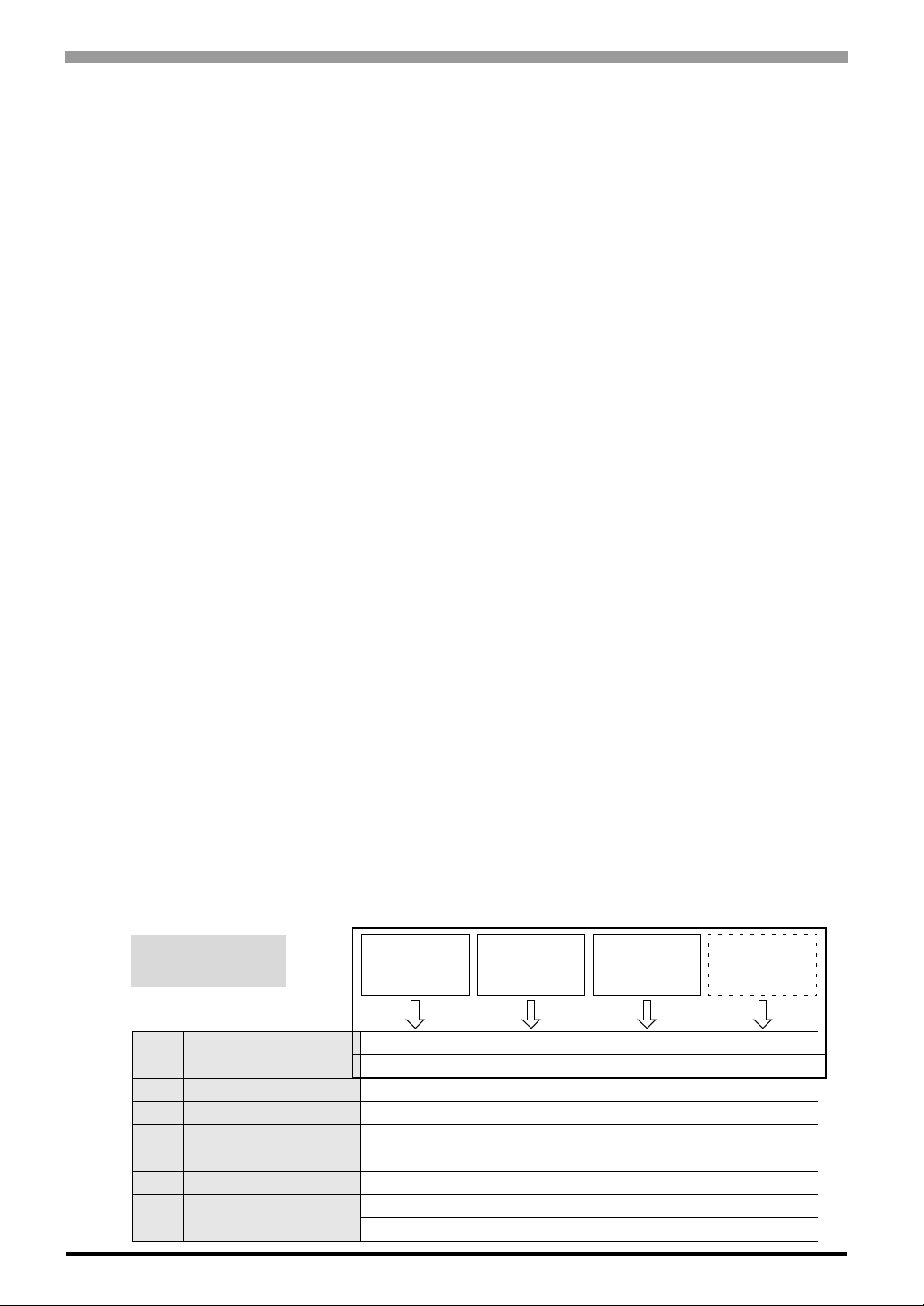
1.1.3 CANopen Profiles The communication profile
The CANopen communication profile is specified into four message types by the CiA DS-301.
• Real-time Data (PDO: Process Data Objects)
• Configuration Data (SDO: Service Data Objects)
• Special Function (Time Stamp, Sync Message, Emergency Message)
• Network Administration Messages (Boot-up Message, NMT Message, Error Control)
For the details, please see the GP- Pro EX Reference Manual “Controlling External I/O”
The device profile
The most important types of devices used in factory automation are described in the “Device profiles”. They
also define device functionalities.
Examples of the standard devices described are:
• digital and analog input/output modules (DSP-401),
• motors (DSP-402),
• measurement device (DSP-404),
• other devices (DSP-4xx).
CANopen
is based on CAL
7 APPLICATION
6 PRESENTATION EMPTY
5 SESSION EMPTY
4 TRANSPORT EMPTY
3 NETWORK EMPTY
2 LINK = LLC + MAC CAN 2.0 A and B + ISO11898
1 PHYSICAL
Device Profile
CiA DSP-401
I/O modules
CiA DS-301 = Communication profile
CAL = CAN Application Layer
CAN 2.0 A and B = ISO11898-1 and 2
ISO 1 1898 + DS-102
Device Profile
CiA DSP-402
Drives
Device Profile
CiA DSP-404
Measuring devices
Device Profile
CiA DSP-4xx
1-2
Page 12

1.1.4 CANopen Features
• open fieldb us (specifications have been released),
• maximum communication speed of 1Mbits/s,
• noise resistance improved by the resend process of the hardware,
• interoperability and interchangeability of devices,
• supported by a large number of international manufacturers (approximately 500 member companies),
• access to all device parameters,
• supports cyclic communication and acyclic communication (event-driven), thereby reducing bus data
volume and increasing response speed.
1.1.5 CANopen Standards
CANopen specifications are defined by the CiA group and can be accessed on the group site at
http://www.can-cia.org/. The sourcecodes for master and slave devices are available from the various
suppliers.
Chapter 1 Introduction
1-3
Page 13
Hybrid Terminal Block Hardware Manual
1.2 System Design
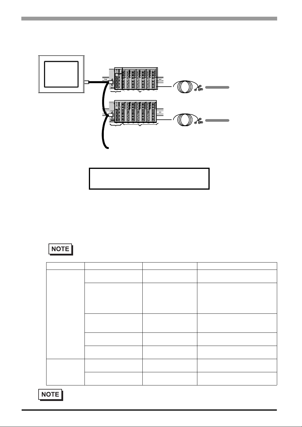
CANopen master,
GP unit etc.
(1)
*1
7 EX Modules (max.)
HTB
HTB
7 EX Modules (max.)
IO Cable
(Prepared by user)
IO Cable
(Prepared by user)
Various types of I/O
equipment
Indicators, LEDs,
sensors, switches,
and so on
Various types of I/O
equipment
Indicators, LEDs,
sensors, switches,
and so on
•
•
•
GP Interface
(1) CANopen Interface
*1 Up to 63 CANopen slaves, Hybrid Terminal Block, can be connected to the CANopen Master , (GP300 0
Series CANopen board type or L T3000 Series using CANopen Master Unit) with CANopen transfer cables
and connectors shown as follows;
Recommended Cable Connector:
CiA-recommended CANopen (CiA DR-303-1) compatible DSUB 9-pin connector (DIN41652).
CANopen Recommended Transfer Cable:
CiA-recommended CANopen (CiA DR-303-1) compatible twisted pair cables with shield.
1-4
Recommended
Cable
Connector
CANopen
Recommended
Transfer Cable
• CANopen communication cables and cable connectors are not supplied with the CANopen
Master Unit. Users must prepare cables.
• Please use your own cables or cable connectors with your guarantee.
Model No. Manufacturer Description
TSXCANKCDF180T <Schneider Electric>
TSXCANKCDF90T
TSXCANKCDF90TP
VS-09-BU-DSUB/CAN <PHOENIX CONTACT>
SUBCON-PLUS-CAN/AX <PHOENIX CONTACT>
SUBCON-PLUS-CAN/PG
SUBCON-PLUS-CAN
TSX CAN CA50/
TSX CAN CA100
TSX CAN CB50/
TSX CAN CB100
<Schneider Electric>
<PHOENIX CONTACT>
<Schneider Electric>
<Schneider Electric>
Straight connector with terminal
selector switch attached.
Right-angled connector with terminal
selector switch attached.
Only for use for GP-3300 Series
CANopen board type and LT3000
Series using CANopen Master Unit.
Connector with terminal block
attached with terminal selector
switch attached.
Straight connector with terminal
selector switch attached.
Right-angled connector with terminal
selector switch attached.
Cable for CANopen
(IEC60332-1) 50 m/100 m
UL-authenticated cable for CANopen
(IEC60332-2) 50 m/100 m
Page 14

1.3 Accessories
All accessories listed here are produced by Pro-face.
1.3.1 Maintenance Item
Product Name Model No. Description
Input/Output
Connector
CA7-HTBCNSET-01
Chapter 1 Introduction
Connector attached to the Input/Output terminals. 13-pin
connector for input and 16-pin connector for output, both
connectors are packed.
1-5
Page 15
Hybrid Terminal Block Hardware Manual
1.4 Part Names and Functions
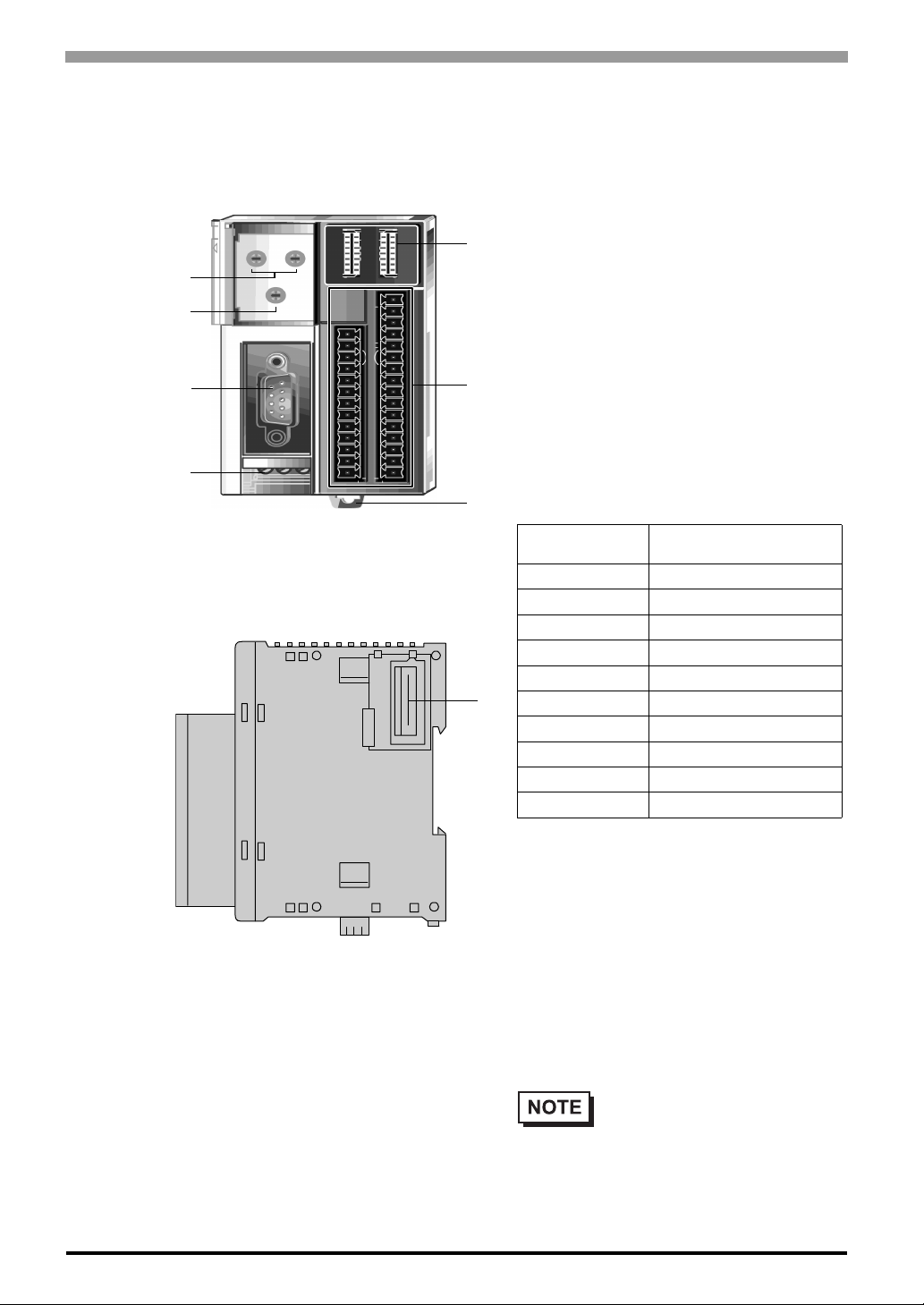
A
B
C
D
Front
Right side
* The Interface (1) on the Left side of HTB is
unable to use.
A: Upper Rotary DIP switch
Define the CANopen node ID (1 to 127). When
using GP3000 Series CANopen board type or
LT3000 Series using CANopen Master Unit as a
E
master, available range of node ID is 1 to 63. Do
not use the same node ID twice in the network.
• Left Rotary DIP switch : Sets tens place with 0
to12 (decimal number)
• Right Rotary DIP switch : Sets ones place with 0
F
G
to 9 (decimal number)
B: Lower Rotary DIP switch
Define the baud rate. Set the baud rate with 0 to 9
(decimal number). Set the baud rates identical to
those on the master unit (such as GP3000 Series
CANopen board type or LT3000 Series using
CANopen Master Unit)
Position (lower
encoder rate)
0 10 kbits/s
1 20 kbits/s
2 50 kbits/s
3 125 kbits/s
4 250 kbits/s
H
*1The value 8 is used to search automatically
*2 If the baud rates of HTB and all CANopen
5 500 kbits/s
6 800 kbits/s
7 1 Mbits/s
8 Automatic
9 Default rate (250 kbits/s)
for the bus transmission speed. The search
starts at a value of 1 Mbits/s then progressively lowers over successive searches until
communication is established on the bus.
The automatic search only works on an operational CANopen network.
Slaves on the network are set to “Automatic,” communication will not function correctly. Be sure to set a different baud rate on at
least one or more CANopen Slaves.
Baud Rate
*1 *2
1-6
• GP3000 Series CANopen board
type or LT3000 Series using
CANopen Master Unit is corresponding to the baud rate
between 50 kbits/s and 1 Mbits/s.
Page 16
Chapter 1 Introduction
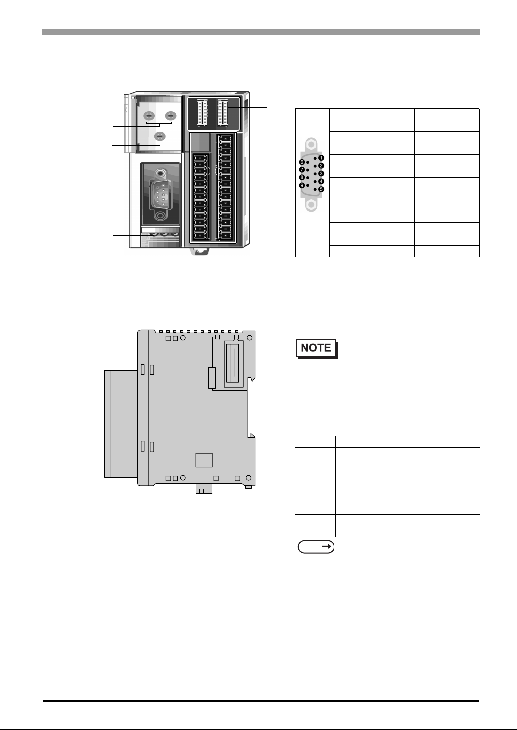
C: Field bus interface
A 9-pin plug DSUB connector is used to connect
the interface module to a CANopen field bus. This
bus is not insulated internally.
E
A
B
C
D
Front
F
G
Recommended cable connector:
CiA-recommended CANopen (CiA DR-303-1) compatible DSUB 9-pin connector (DIN41652).
Recommended network cable:
CiA-recommended CANopen (CiA DR-303-1) compatible twisted pair cables with shield.
H
Contacts Signal Description
1– –
2 CAN_L CAN-L bus line
CAN_GND
3
4– –
5– –
6GND
7 CAN_H CAN-H bus line
8– –
9– –
Shell FG Frame Ground
• Please use your own cables or
cable connectors with your
guarantee.
CAN Ground
Ground
(Common with
CAN_GND)
Right side
* The Interface (1) on the Left side of HTB is
unable to use.
D: Electrical supply Interface
Terminal f or an external 24 VDC supp ly of the HTB.
E: Indicator LED
LED
PWR
RUN
ERR
I0 - I11
Q0 - Q7
SEE
F: In/Output Terminals
Input/Output terminals.
G: Hook
A hook to fix HTB on the DIN rail.
H: Extension Connector
Connects only EX module, up to 7.
Indicates the presence of a 24 VDC
power supply to HTB.
2 (RUN) and 3 (ERR) show the
data exchange status between the
communication units that can
transmit data.
Reflect the I/O status of HTB’s
integrated I/O.
1.4.1 Indicator LEDs Details (p.1-8)
Status
1-7
Page 17
Hybrid Terminal Block Hardware Manual
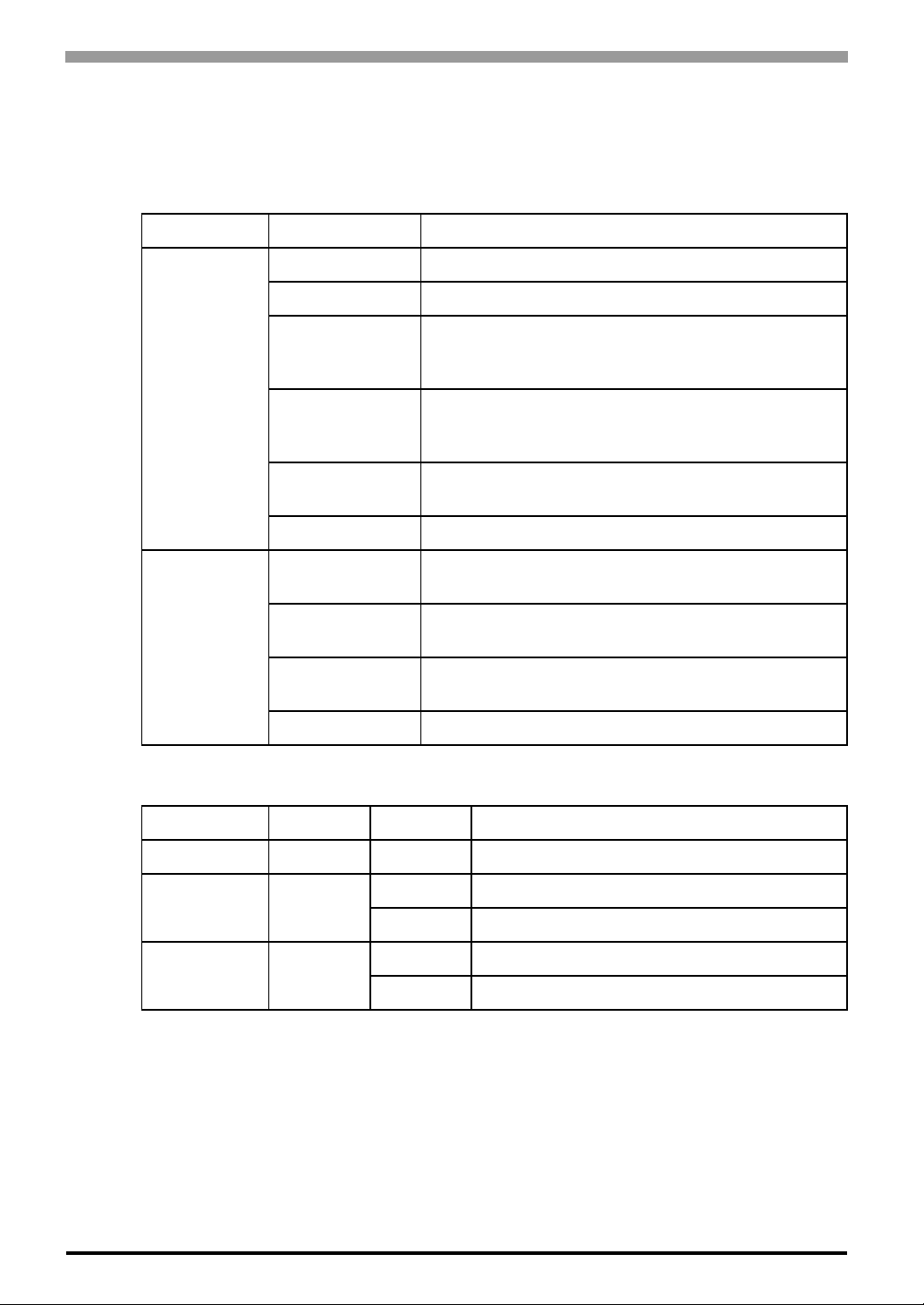
1.4.1 Indicator LEDs Details CANopen Communication LEDs
Standard DRP303-3 defines the RUN and ERR LEDs and their different statuses.
LED Type of fla sh i ng Description
off No error .
random flashing Automatic search for the bus communication speed.
ERR (red)
RUN (green)
I/O status LEDs
Name LED color Status Function
flashing: 1
flash
flashing: 2
flashes
flashing: 3
flashes
on Bus OFF. Status of the HTB: Bus OFF.
random
flashing
continuous
flashing
flashing: 1
flash
on Module status: Operational.
Warning limit reached. An internal error counter in the
CAN controller has reached or exceeded the error frame
limit threshold number (error frame).
Error control event. Detection of a guard event (NMTSlave or NMT-master) or a heartbeat event (Heartbeat
consumer)
Synchronization error: message not received within the
defined period.
Automatic search for the bus communication speed.
Module status: Pre-operational.
Module status: Stopped.
1-8
PWR (power) green on Presence of 24 VDC for the HTB
on Input set to 1
I0 to I11 green
off Input set to 0
on Active output
Q0 to Q7 green
off Inactive output
Page 18

2 Specifications
1. General Specifications
2. Performance Specifications
3. External Dimensions
This chapter describes the general, functional and interface spe ci fications of the HTB as well as its
dimensions.
2-1
Page 19
Hybrid Terminal Block Hardware Manual
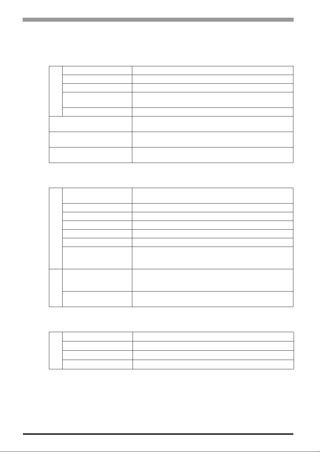
2.1 General Specifications
2.1.1 Electrical Specifications
Input Voltage DC24V
Rated Voltage DC20.4 to 26.4V (including ripple)
Allowable Voltage Drop 10ms (max.) (DC24V)
Power Consumption
Power Supply
In-Rush Current 50A (max.) (DC24V)
Voltage Endurance
Insulation Resistance
Noise resistance
IEC 1131-2
2.1.2 Environmental Specifications
19W (DC26.4V)
(Communication module with (max.) 7 EX modules.)
AC500V, 1 minute (between power and ground terminals)
AC500V, 1 minute (between I/O and ground terminals)
10 MΩ (min.) (DC500V) (between power and ground terminals)
10 MΩ (min.) (DC500V) (between I/O and ground terminals)
DC power terminals: 1kV, 50 ns to 1µs
I/O terminals (coupling clamp): 1.5 kV, 50 ns to 1 µs
Surrounding Air
Temperature
Storage Temperature -25 to +70°C
Ambient Humidity 30 to 95% RH (Not condensing)
Storage Humidity 30 to 95% RH (Not condensing)
Pollution Degree For use in Pollution Degree 2 environment
Physical
Atmosphere Free of corrosive gases
Air Pressure Vibration
Resistance (availment
altitude)
Vibration Resistance
Concussion Resistance
Mechanical
2.1.3 Structural Specifications
Installation Configuration Attachment via 35mm DIN rail
Protective structure IP20
Cooling Method Natural air circulation
Installation
Weight Approx. 185g [0.4lb] max. (unit only)
0 to 55°C
Operation: from 0 to 2000 m
Transport: from 0 to 3000 m
from 10 to 57 Hz amplitude 0.075 mm [0.003 in.],
from 57 to 150 Hz acceleration 9.8 m/s2, 2 hours per axis on
each of three mutually perpendicular axes.
2
147 m/s
, 1 1 ms duration, 3 shocks per axis, on three mutually
perpendicular axes (IEC 61131).
2-2
Page 20

2.2 Performance Specifications
2.2.1 Input Specifications
Input points 12 inputs with common line (source/sink input signal)
Rated input voltage DC24V
Input voltage range from DC20.4 to 26.4V
Rated input current I0, I1, I6, I7:5mA/input (DC24V)
Input impedance I0, I1, I6, I7: 5.0 kΩ
Switching time at high status
(ON Time)
Switching time at low status
(OFF Time)
Isolation Between input terminals: not isolated
Filtering: 3 possibilities
• none
•3 ms
• 12 ms
Input type Type 1 (IEC 61131)
External load for I/O
interconnection
Signal determination method Static
Input cable length 3 m [118.11 in.] for compliance with electromagnetic immunity
Connector insertion/removal
durability
Chapter 2 Specifications
I2 to I5, I8 to I11: 7mA/input (DC24V)
I2 to I5, I8 to I11: 3.4 kΩ
I0, I1, I6, I7: 35 µs + filter value
I2 to I5, I8 to I11: 40 µs + filter value
I0, I1, I6, I7: 45 µs + filter value
I2 to I5, I8 to I11: 150 µs + filter value
Internal circuit: photocoupler isolated (isolation protection put to
AC500V rms)
I0 to I11
Not needed
100 times (min.)
2-3
Page 21
Hybrid Terminal Block Hardware Manual
Input Operating Range
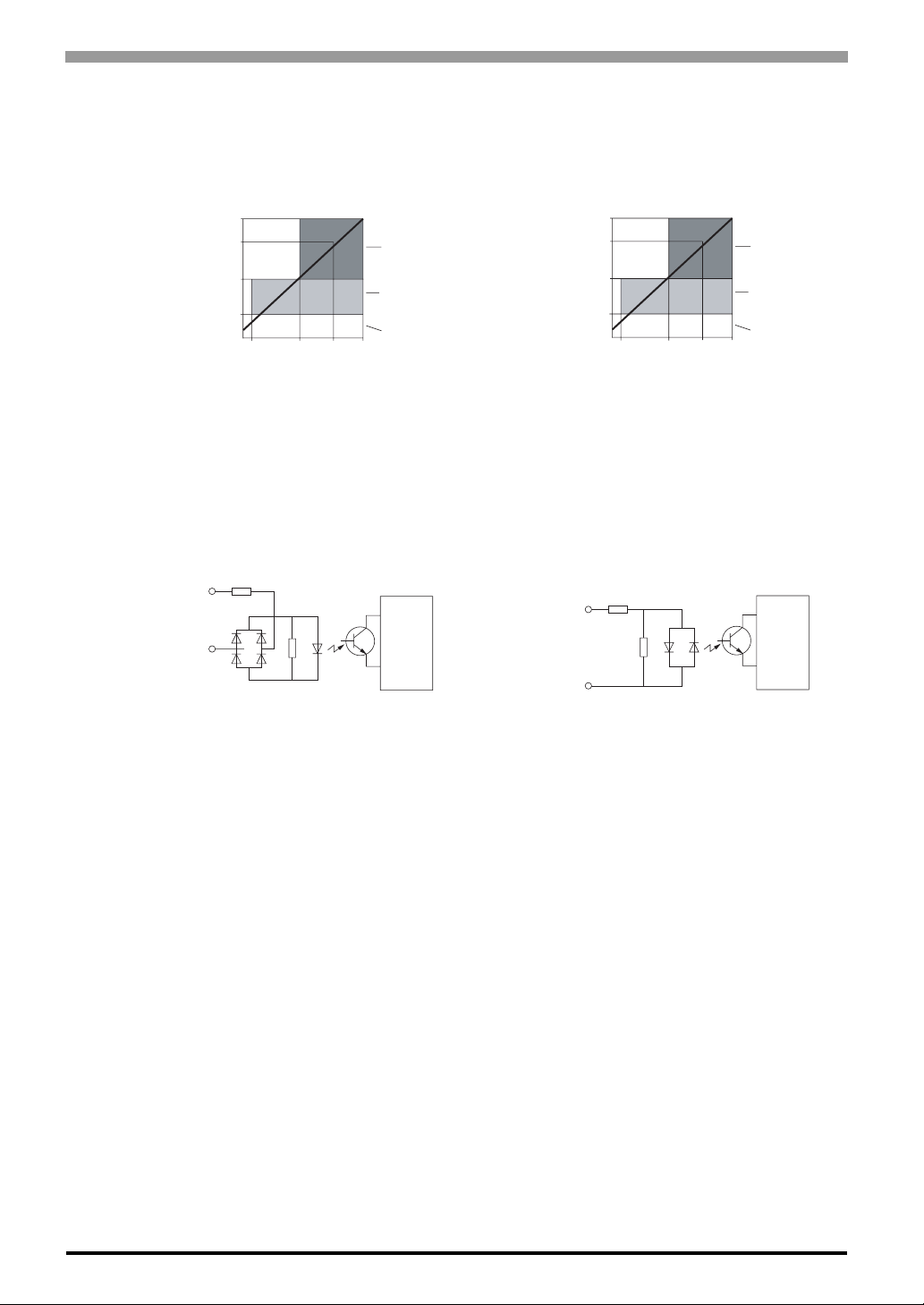
The input operating range of the Type 1 (IEC 61131-2) input module is shown below.
Inputs I0, I1, I6, and I7
26.4
24
15
5
0
1.2 3.1 5 5.6
Input Voltage (V DC)
Input Current (mA)
Input Internal Circuit
The internal input circuit is described below.
Sink Or Source Input
(high speed)
Inputs I0, I1, I6, and I7
Input
COM
ON Area
Transition
Area
OFF Area
Circuit
Internal
Inputs I2 to I5, I8 to I11
26.4
24
15
5
0
1.2 4.2 7 7.7
Input Voltage (V DC)
Input Current (mA)
Sink Or Source Input
(standard)
Inputs I2 to I5, I8 to I11
Input
COM
ON Area
Transition
Area
OFF Area
Circuit
Internal
2-4
Page 22

2.2.2 Output Specifications
RISK OF UNINTENDED EQUIPMENT OPERATION
Do not exceed the recommended temperature / simultaneous I/O usage guidelines.
Exceeding the temperature and / or simultaneous I/O in the “on” state can cause
overheating of HTB and / or the I/O expansion modules, resulting in unexpected ope ration
of the inputs and outputs. Depending on the I/O configuration, unintended equipment
operation can occur.
Failure to follow this instruction can result in death, serious injury or equipment damage.
Source Transistor Output Characteristics Q0,Q1
Chapter 2 Specifications
Output type Source output
Output points per comm on Li ne 2
Rated load voltage DC24 V
Maximum load current 1 A per common line
Operating load voltage range from DC20.4 to 28.8 V
Voltage drop (on voltage)
Rated load current 0.3 A per output
Inrush current 1 A (max.)
Leakage current 0.1 mA (max.)
Clamping voltage DC39 V ±1 V
Maximum lamp load 8 W
Inductive load L/R = 10 ms (DC28.8 V, 1 Hz)
External current draw
Isolation
Average number of connector insertions/
removals
Output delay - turn on time 5 µs (max.)
Output delay - turn off time 5 µs (max.)
DC1 V (max.) (voltage between COM and
output terminals when output is on)
100 mA (max.), DC24 V
(power voltage at the -V terminal)
Between output terminal and internal circuit:
photocoupler isolated (isolation protection up
to AC500 V rms)
Between output terminals: not isolated
100 times (min.)
2-5
Page 23
Hybrid Terminal Block Hardware Manual
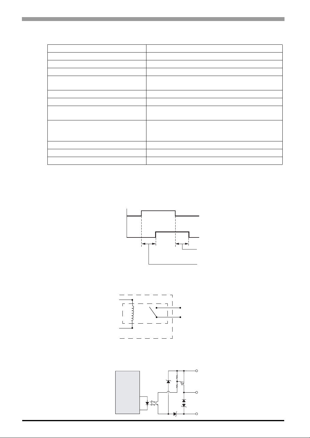
Relay Output Specifications Q2 to Q7
Number of outputs 6 relay outputs
Output points per common line - COM1 3 NO contacts
Output points per common line - COM2 2 NO contacts
Output points per common line - COM3 1 NO contact
Maximum load current
Minimum switching load 0.1 mA/DC0.1 V (reference value)
Initial contact resistance 50 mΩ (max.)
Mechanical life
Dielectric strength
Connector insertion/removal durability 100 times (min.)
Output delay - turn on time 10 ms (max.) (Bounce time not included)
Output delay - turn off time 5 ms (max.) (Bounce time not included)
Output delay and contact
2 A per output
8 A per common line
20,000,000 operations (min.) (rated load 18,000
operations/h)
Between output to internal circuit: AC1500 V rms, 1 min
Between output to terminals (COMs): AC750 V rms, 1
min
Relay Output Delay
The output delay is illustrated below.
Command
Output Relay Status
ON
OFF
ON
OFF
Relay Output Contact
The relay output contact is shown below.
Internal Circuit
Transistor Source Output Contact
The transistor source output contact is shown below.
Internal
Circuit
N.O
OFF delay: 5 ms (max.)
ON delay: 10 ms (max.)
Terminal block
Qx (Load)
COM
COM (+)
Output
2-6
-V
Page 24
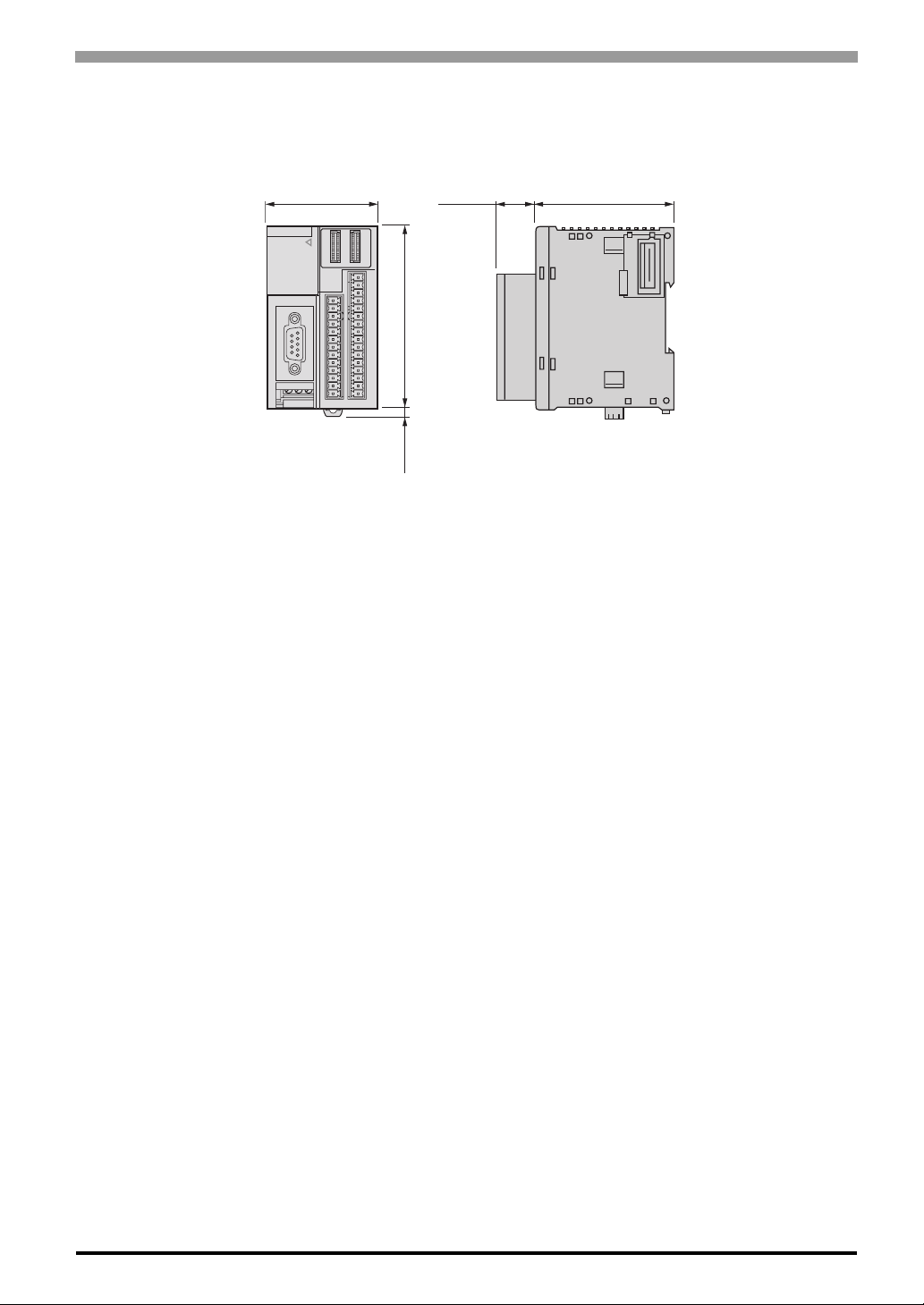
2.3 External Dimensions
Unit: mm[in.]
Chapter 2 Specifications
55 [2.17]
Front
*1 8.5 mm [0.33 in] when the clamp is pulled out.
14.6
[0.57]
90 [3.54]
*1
4.5
[0.18]
70 [2.76]
Right side
2-7
Page 25

Hybrid Terminal Block Hardware Manual
2-8
Page 26

3 Installation and
Wiring
1. Installation
2. Wiring
3-1
Page 27
Hybrid Terminal Block Hardware Manual
3.1 Installation
RISK OF UNINTENDED EQUIPMENT OPERATION
Do not add or remove an expansion module to or from the system before first removing all
power. Adding or removing an expansion module while under power can cause damage to
the module and the system resulting in unexpected operation of inputs and outputs.
Depending on the I/O configuration, unintended equipment operation can occur.
Failure to follow this instruction can result in death, serious injury or equipment damage.
• All expansion modules such as EX modules should be installed in the HTB before installing an
island on a DIN rail. The island should be removed from a DIN rail before disassembling the different modules.
RISK OF UNINTENDED EQUIPMENT OPERATION
Keep adequate spacing around the island for proper ventilation and to maintain an ambient
temperature between 0°C and 55°C.
Overheating of the HTB and/or the I/O expansion modules can result in unexpected
operation of inputs and outputs. Depending on the I/O config uration, unintended equiment
operation can occur.
Failure to follow this instruction can result in death, serious injury or equipment damage.
RISK OF UNINTENDED EQUIPMENT OPERATION
Do not place heat generating devices such as transformers and supply blocks under the
island.
Heat generating devices in proximity of the HTB and I/O expansion modules could result in
elevated temperatures and overheating, and can result in unexpected operation of inputs
and outputs. Depending on the I/O configuration, unintended equipment operation can
occur.
Failure to follow this instruction can result in death, serious injury or equipment damage.
3-2
Page 28
3.1.1 Installation Requirements
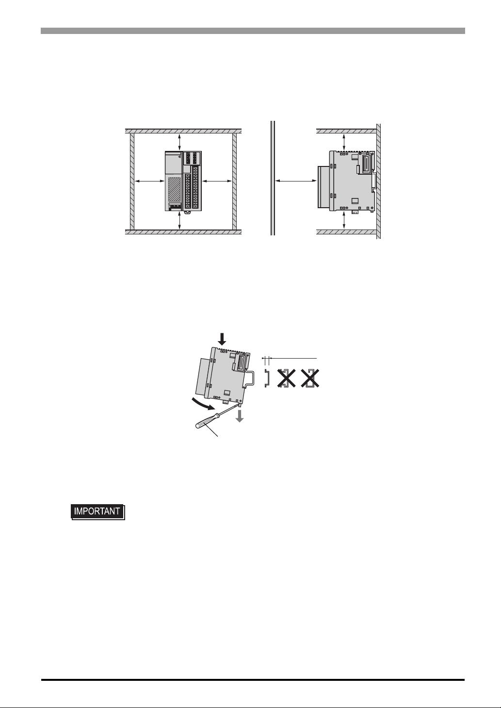
• In order to ensure proper serviceability, operability and airflow, provide space between the HTB and
structural objects or other parts as the figure shows.
Chapter 3 Installation and Wiring
Unit : mm [in.]
20 [0.79]
40
[1.57]
20 [0.79]
40
[1.57]
3.1.2 35 mm [1.38 in.] DIN rail mounting
(1) Put the upper groove of the unit on the upper edge of the DIN rail. Push the lower side of the unit to the
lower edge of the DIN rail unit it clicks.
1
2
20 [0.79]
80
[3.15]
20 [0.79]
15 mm [0.59 in.]
Push down to remove.
With a flat-blade driver
(2) While pushing down the hook in the direction of the arrow with a flat-blade driver, pull the lower side of
the unit and remove the unit from the DIN rail.
• Check the vertical direction of the unit. Attach the unit on to the vertical plane
properly. Improper mounting of the unit may prevent heat release and proper
operation of the unit.
• The unit release hooks are kept open when not used. Make sure that the unit
release hooks close properly and the unit is firmly fixed on the DIN rail.
3-3
Page 29
Hybrid Terminal Block Hardware Manual
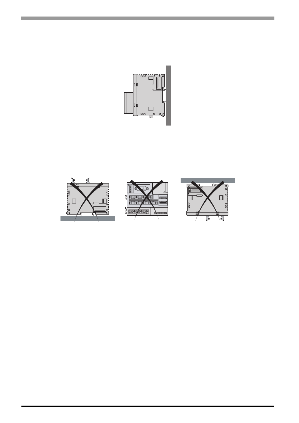
Correct Mounting Position
HTB and expansion I/O modules must be mounted horizontally on a vertical plane as shown in the figures
below.
Incorrect Mounting Position
The following diagrams show the incorrect mounting positions for the HTB and expansion modules.
3-4
Page 30
Chapter 3 Installation and Wiring
3.2 Wiring
DANGER OF ELECTRIC SHOCK
Be sure to remove ALL power from ALL devices before connecting or disconnecting inputs
or outputs to any terminal or installing or removing any hardware.
Make sure you have COMPLETELY powered down ALL devices before connecting or
disconnecting the bus or network.
Failure to follow this instruction will result in death, serious injury or equipment damage.
RISK OF UNINTENDED EQUIPMENT OPERATION
If outputs should fail, outputs may remain on or off. Where personnel and or equipment
hazards exist, use an appropriate hard-wired safety system.
Failure to follow this instruction can result in death, serious injury or equipment damage.
To avoid an electric shock, prior to connecting the HTB’s power cord terminals to the power
terminal block, confirm that the HTB’s power supply is completely turned OFF, via a
breaker, or similar unit.
Any other power level can damage both the HTB and the power supply.
When the FG terminal is connected, be sure the wire is grounded.
When turning on the master and slave separately on the CANopen network, the CANopen
Slaves (HTB or otherwise) must be turned on first, and then the CANopen master (GP3000
Series CANopen board type or LT3000 Series using CANopen Master Unit) must be turned
on last. Not doing so may cause the CANopen network to not operate properly.
3-5
Page 31
Hybrid Terminal Block Hardware Manual
3.2.1 Wiring Requirements
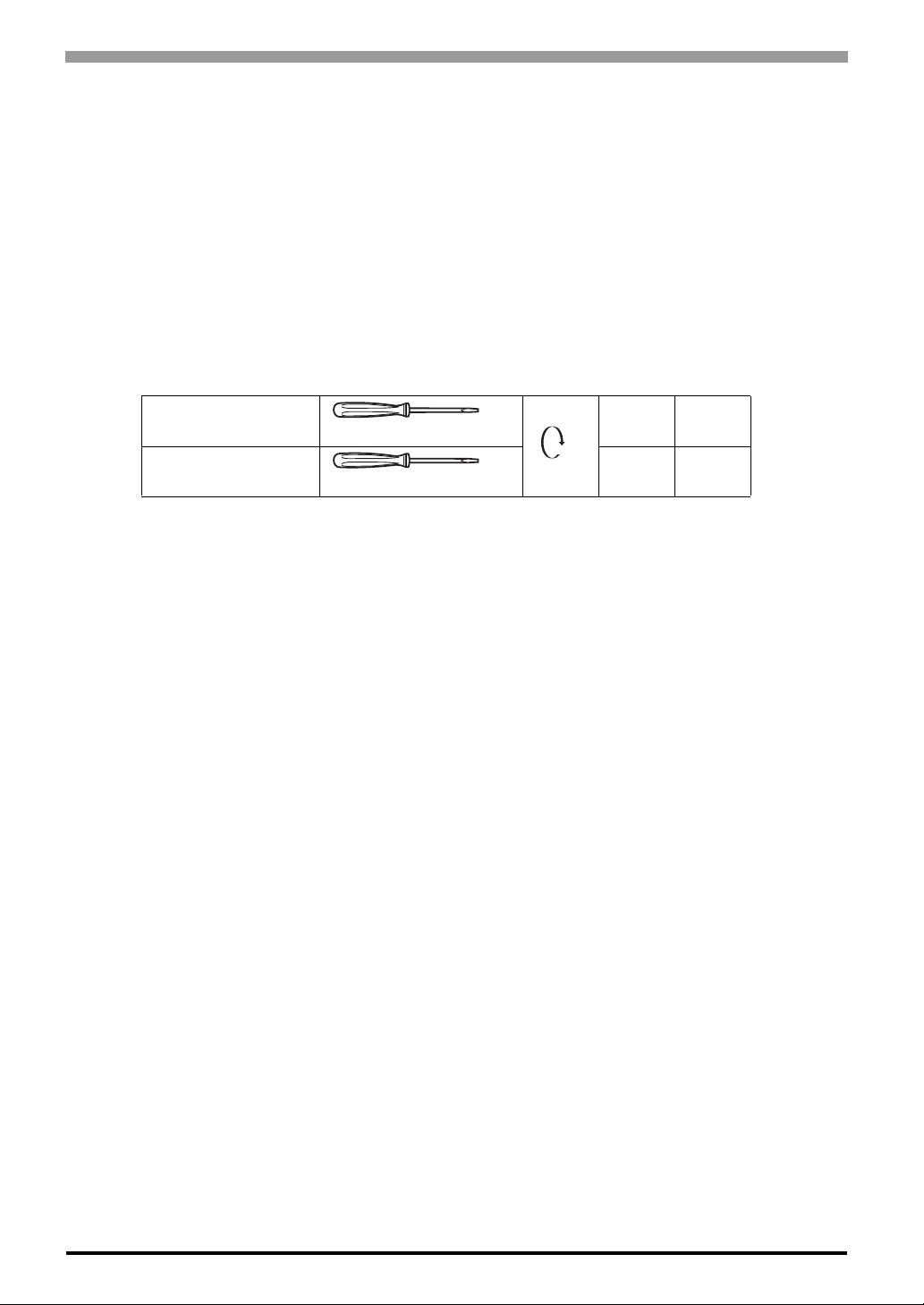
Power Cord and Input/Output cables Specifications
Power Cord
2
to 1.5mm2 (A WG 18 and AWG 16). Use the shortest wire length possible. The grounding wire should
1 mm
be 1.50 mm2 (AWG 16).
I/O cables
2
0.20 mm
(accepts up to two wires fitted with cable ends or tags)
to 1.31 mm2, (AWG 24 to AWG 16).
Power supply
section
In/Output terminal
connector
Ø 3.5 mm [0.14 in.]
Ø 2.5 mm [0.10 in.]
N·m 0.6
C
N·m 0.4
3-6
Page 32
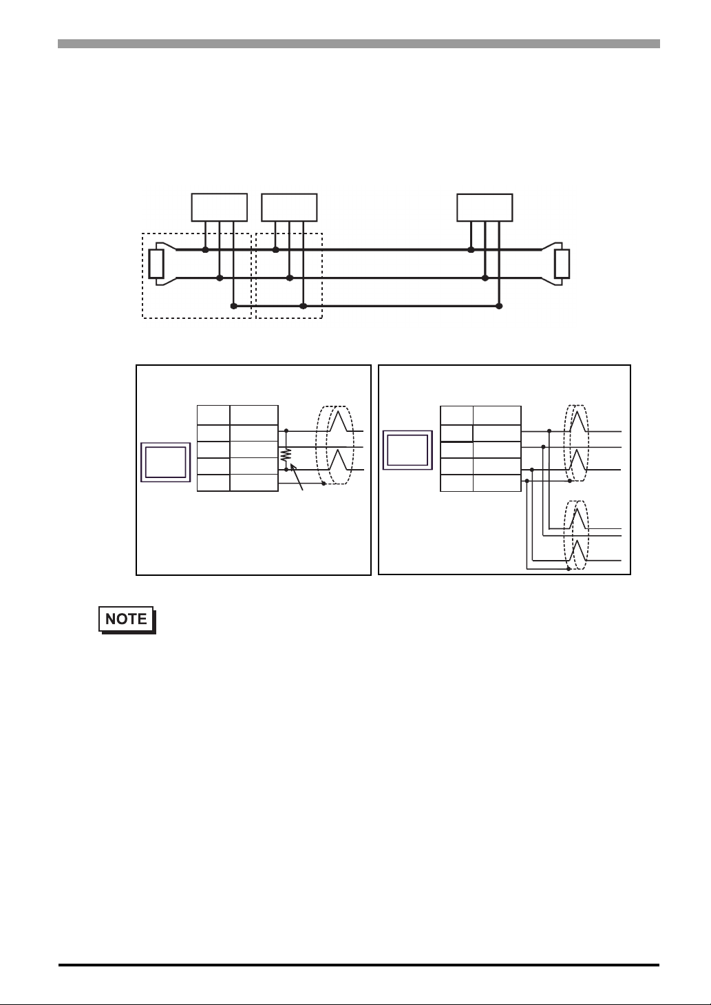
3.2.2 CANopen wiring
The CANopen interface uses DSUB 9-pin plug connector. The plug is assigned with the CAN_H, CAN_L and
CAN_GND connections. CAN_H and CAN_L are two physically different bus levels. CAN_GND is the
common reference potential.
Chapter 3 Installation and Wiring
Node 1
Diagram 1
Node 2
Diagram 2
CAN_H
LT
CAN_L
Twisted Pair Cable
CAN_GND
LT = Line Termination
Diagram 1 Diagram 2
ShieldD-sub 9 pin (socket)
Termination
Resistance
GP
GP
Pin
2
3
7
Signal
name
CAN-L
CAN-GND
CAN-H
FGShell
Node n
D-sub 9 pin (socket)
Pin
2
3
7
Signal
name
CAN-L
CAN-GND
CAN-H
FGShell
LT
Shield
Shield
• The cable’s resistance value should be 70mΩ/m or less.
• The above diagrams shows the case used the cable connector “XM2D-0901” by OMRON Co.
Line termination
To min imi ze the re flecti ons from the end of the cable, a line termin ation shall be placed close to the 2 ends of
the bus. Connect both ends of the twisted pair cable(CAN_H and CAN_L) to each LT. Use line termination
whose resistance value is 120 Ω. (5%, 1/4 W maximum)
3-7
Page 33
Hybrid Terminal Block Hardware Manual
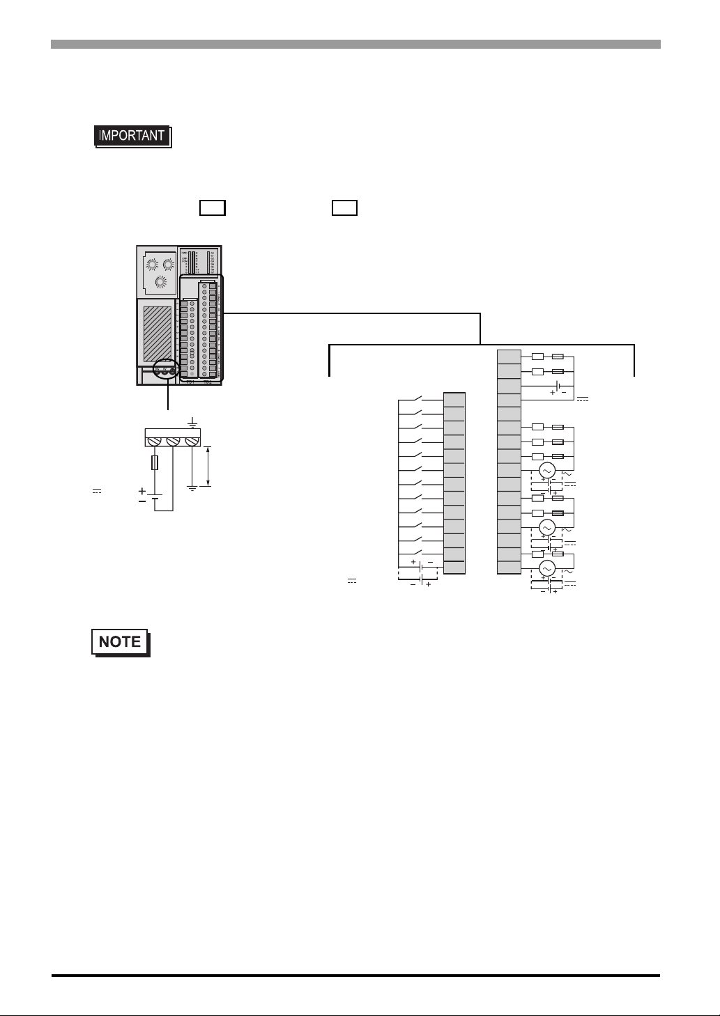
3.2.3 Connecting the Power Cord and Input/Output cables
• Make sure to remove the connectors from the HTB first, then connect cables to
the terminal. Failure to do so may cause an electric shock.
• Be careful when you remove the connectors that are firmly fit.
24 V
– 15 %
+ 9 %
ADDRESS
NOT
0
0
NOT
2
USED
USED
4
12
10
6
8
8
ONESTENS
0
1
2
3
NOT
4
USED
5
6
9
7
8
BAUD RATE
24 V 0 V
indicates a fuse. indicates load.
2
4
6
l ≤ 80 mm [3.15 in.]
Ø1...1.5mm
AWG 18...16
2
L
(1) Sink Input
(2) Source Input
24 V
-15%
+10%
L
0
Q0
1
COM0
(+)
– V
NC
2
3
4
COM1
NC
5
6
COM2
NC
7
COM3
L
Source Output
-15%
24 V
+20%
L
L
L
Relay Output
(1)
(2)
(1)
(2)
(1)
(2)
48…240 V
30 V
L
L
Relay Output
48…240 V
30 V
L
Relay Output
48…240 V
30 V
Q1
0I0
I1
1
I2
Q2
2
I3
Q3
3
I4
Q4
4
I5
5
I6
6
I7
Q5
7
8
I8
Q6
9
I9
10
I10
11
I11
(1)
(2)
Q7
COM
3-8
• Please install an applicable fuse to prevent an overload in the circuit, if necessary.
• The terminals, such as COM0, and COM1 to 3, are not connected together internally.
• The input/output connector is CA7-HTBCNSET-01 made by Pro-face. 13-pin connector for
input and 16-pin connector for output, both connectors are packed.
Page 34
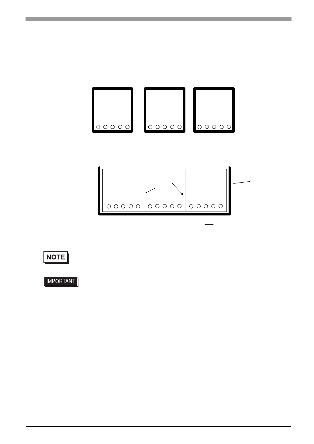
3.2.4 Wiring Precautions
• Power supply wires routed inside the panel must be kept separate from I/O and communication wiring.
Route wiring in separate cable ducting.
Chapter 3 Installation and Wiring
Duct for I/O Signal
Lines
If different wires must be placed in the same duct, separate them with an earthed/grounded divider .
I/O Signal Lines Control Lines Power Lines
Duct for Control
Lines
Grounded
Separators
Duct for Power
Lines
Duct
(non-conducting
resin/plastic)
Earth/Ground
• If the lines cannot be separated, use shielded lines and create a ground from the shield line.
• Use noise-reducing external wiring methods to increase overall system reliability.
• To prevent power surges or noise interference, use ducts to separate all DC I/O
or current circuit wires from communication cables.
• To prevent malfunctions due to noise, communication cables must be wired
separately from high-frequency lines and power lines such as high-voltage lines,
high-current lines, and inverters.
• Take care when wiring output modules that are designed to work as either source or sink. Incorrect wiring
can cause equipment damage.
• Make sure that the operating conditions and environments are within the specification values.
• Use proper wire size to meet voltage and current requirements.
• Fit cable ends to the cables.
3-9
Page 35
Hybrid Terminal Block Hardware Manual
3.2.5 Contact Protection Circuit for Relay and Transistor Outputs
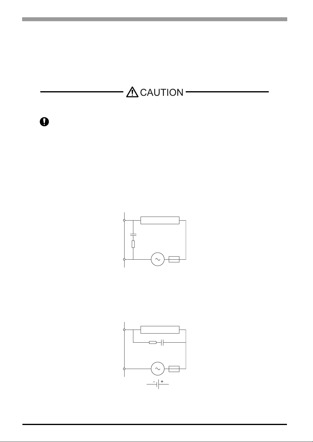
Depending on the load, a protection circuit may be needed for relay outputs. Choose a protection circuit, from
the following diagrams, according to the power supply.
Connect the protection circuit to the outside of the module for the relay outputs.
RISK OF EQUIPMENT DAMAGE
Apply circuit protection to all outputs.
Failure to add a protection circuit can result in the malfunction of the output(s) in the case of
short circuit or overload condition.
Failure to follow this instruction can result in equipment damage.
Protection Circuit A: this protection circuit can be used when the load impedance is smaller than the RC
impedance in an AC load power circuit.
Output Q
Inductive load
C
R
COM
• C represents a value from 0.1 to 1 µF.
• R represents a resistor of approximately the same resistanc e val ue as the load.
Protection Circuit B: this protection circuit can be used for both AC and DC load power circuits.
Output Q
Inductive load
R
C
3-10
COM
or
• C represents a value from 0.1 to 1 µF.
• R represents a resistor of approximately the same resistanc e val ue as the load.
Page 36
Chapter 3 Installation and Wiring
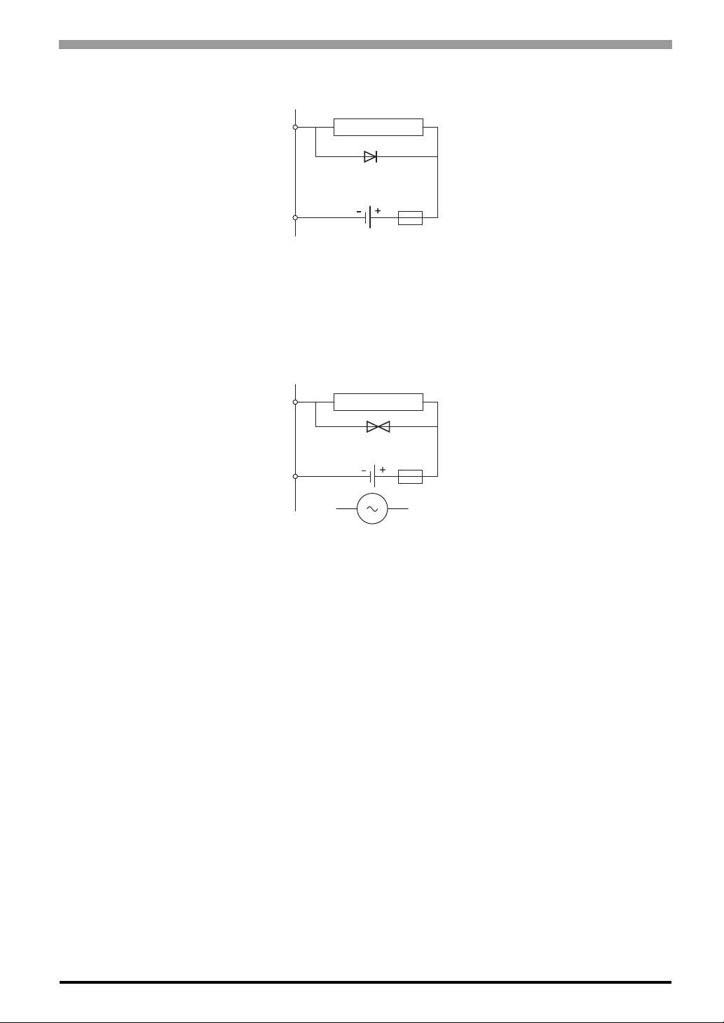
Protection Circuit C: this protection circuit can be used for DC load power circuits.
Output Q
COM
Use a diode with the following ratings:
• Reverse withstand voltage: power voltage of the load circuit x 10.
• Forward current: more than the load current.
Protection Circuit D: this protection circuit can be used for both AC and DC load power circuits.
Output Q
COM
Inductive load
Inductive load
or
3-11
Page 37
Hybrid Terminal Block Hardware Manual
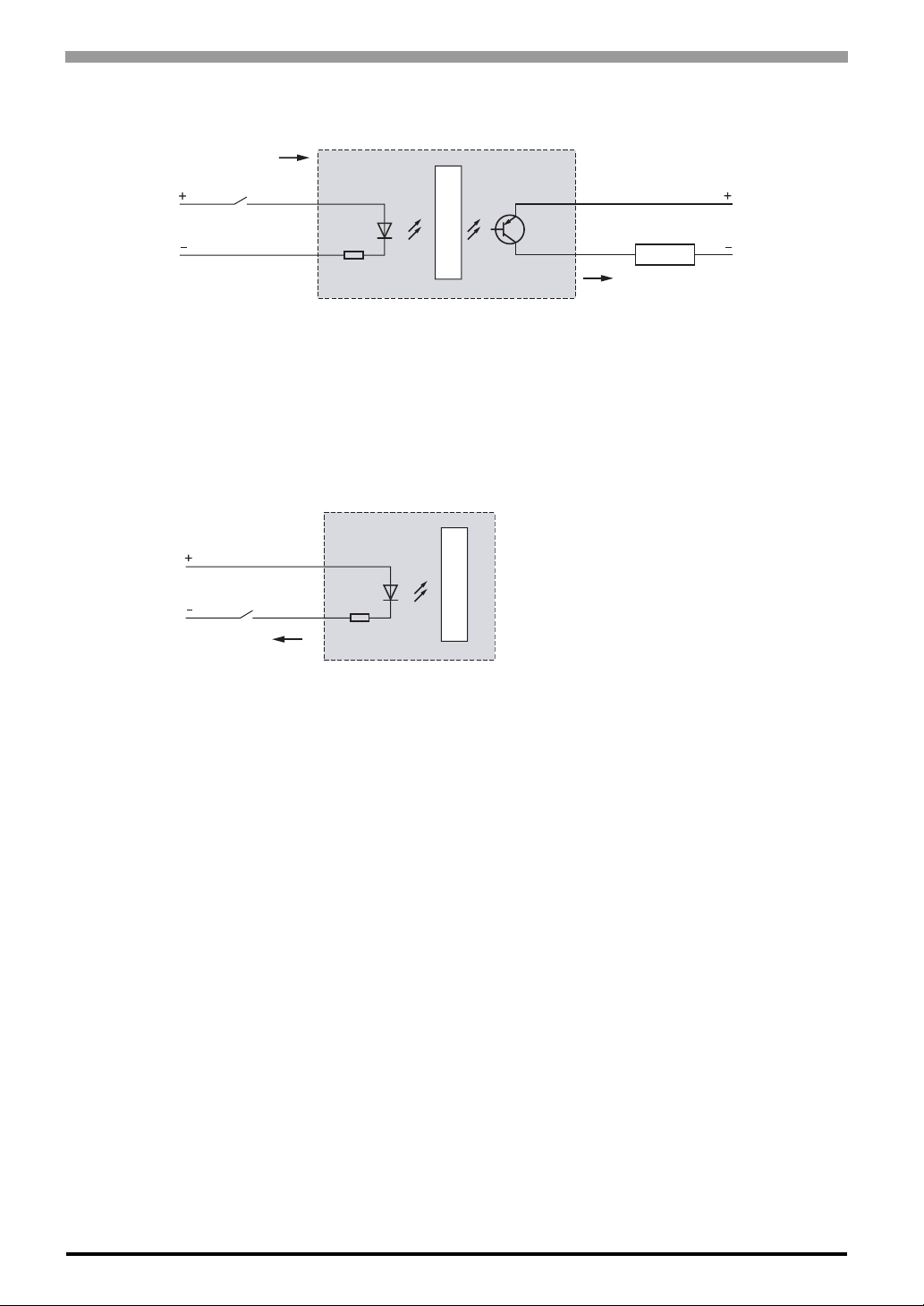
Operation of Sink Inputs / Source Outputs
Electrical
supply
Power supply
common
Input side COM field terminal connects to the "-" terminal or common of the field power supply. Output side
COM field terminal connects to +24V field power supply.
Current
Sensor common
Input
Current Sink Inputs/Current Source Outputs
L
O
G
I
C
Current
Electrical
supply
Output
Load
Operation of Source Inputs
Electrical
supply
Input
common
Current
Current Source Inputs
L
O
G
I
C
The input side COM field terminal connects to the +24V of the field power supply.
3-12
 Loading...