

Page 1

GP2000 Series
VM Unit
User Manual
Page 2

PREFACE
Thank you for purchasing the Pro-face GP2000 VM Unit (GP2000-VM41). The VM
Unit is installed in the rear of the Pro-face GP2000 Series Operator Interface (hereafter referred to as the "GP") and allows the GP to display images taken with a video
camera or sent from a PC.
Please note that you will need GP-PRO/PB III for Windows Ver. 5.05 or higher to
use the entire range of VM Unit features.
This manual provides important information for using the VM Unit with the GP. Be
sure to read the relevant sections prior to using this unit, and store it in an easy-tofind, safe place.
NOTE:
1) It is forbidden to copy the contents of this manual, in whole or in part, without
the express permission of Digital Electronics Corporation of Japan.
2) The information provided in this manual is subject to change without notice.
3) This manual has been written with care and attention to detail; however,
should you find any errors or omissions, please contact Digital Electronics
Corporation and inform them of your findings.
4) Please be aware that Digital Electronics Corporation shall not be held liable by
the user for any damages, losses or third party claims arising from any uses of
this product.
5) This unit is UL/c-UL (CSA) approved and CE marked. However, when this
unit is installed in a GP2000 series unit that does
(CSA) and CE standards, the combination will cause the VM Unit to fail to
comply with CE and UL/c-UL (CSA) standards.
© 2001, Digital Electronics Corporation.
not comply with UL/c-UL
The company names and product names in this manual are the registered trademarks
of their respective companies.
GP2000 Series VM Unit User Manual
E1
Page 3
TABLE OF CONTENTS
PREFACE ............................................................................................................................. E1
TABLE OF CONTENTS ........................................................................................................ E2
Essential Safety Precautions ................................................................................................ E3
Package Contents................................................................................................................. E5
Applicable products............................................................................................................... E5
Optional ITEMS..................................................................................................................... E5
Related manuals .................................................................................................................. E6
UL/c-UL (CSA) APPLICATION.............................................................................................. E7
CE Marking .......................................................................................................................... E7
Documentation Conventions.................................................................................................E8
Chapter 1 : Overview
1.1 VM Unit Features.......................................................................................................E1-1
1.2 System Design .......................................................................................................... E1-1
1.3 Using the Screen Editor Software ............................................................................. E1-2
Chapter 2 : SPECIFICATIONS
2.1 General Specifications...............................................................................................E2-1
2.1.1 Electrical .......................................................................................................E2-1
2.1.2 Environmental...............................................................................................E2-1
2.1.3 Structural ...................................................................................................... E2-2
2.2 Functional Specifications........................................................................................... E2-2
2.2.1 Video Display................................................................................................E2-2
2.2.2 VGA/SVGA Display ......................................................................................E2-3
2.2.3 External Interface..........................................................................................E2-4
2.3 Interface Specifications .............................................................................................E2-4
2.3.1 Video Input Interface.....................................................................................E2-4
2.3.2 RGB Input and Output Interfaces ................................................................. E2-5
2.4 Part Names and Functions ........................................................................................E2-6
Chapter 3 : Installation and Wiring
3.1 Installing the VM Unit.................................................................................................E3-1
3.2 Cable Connection ..................................................................................................... E3-2
Chapter 4 : Setup
4.1 Video Window Adjustment ........................................................................................ E4-1
4.1.1 SET UP VIDEO OPERATION.......................................................................E4-1
4.1.2 VIDEO DISPLAY ADJUSTMENT..................................................................E4-2
4.1.3 SET UP CAPTURE OPERATION.................................................................E4-5
4.2 VGA/SVGA Display Adjustment ................................................................................ E4-6
Chapter 5 : Error Handling
5.1 Troubleshooting......................................................................................................... E5-1
5.1.1 Possible GP or VM Unit Problems...............................................................E5-1
5.1.2 When Nothing Appears on the GP Screen ..................................................E5-2
5.1.3 Video Input Signal Error Messages ............................................................. E5-2
5.2 Checking the VM Unit................................................................................................ E5-3
E2
GP2000 Series VM Unit User Manual
Page 4
ESSENTIAL SAFETY PRECAUTIONS
This manual includes procedures that must be followed to operate the VM Unit
correctly and safely. Be sure to read this manual and any related manuals thoroughly
to understand the correct operation and functions of this unit.
Safety Icons
Throughout this manual the following icons are provided next to certain precautions
to ensure safe operation of the VM Unit. Such precautions provide essential safety
information that must be followed.
These icons indicate the following levels of danger.
Indicates situations where severe bodily
WARNING
!!
!
!!
Warning
injury, death or major equipment damage can
occur.
Indicates situations where slight bodily
!!
!
!!
Caution
CAUTION
injury or machine damage can occur.
WARNINGS
• To prevent an electric shock, prior to VM Unit installation be sure to
check that the GP and VM Units are not connected to a power supply.
• Do not touch the circuit board attached to the inner face of the VM
Unit.
• Do not modify the design of the VM Unit. Doing so may cause a fire
or electric shock.
• Design your system so that the equipment will not malfunction due to
a communication fault between the GP and a PLC. This is to prevent
any possibility of bodily injury or equipment damage.
To prevent VM damage
• Do not allow water, liquids, or metal objects to enter the VM Unit. Otherwise, a
malfunction or electric shock may occur.
• Do not use the VM Unit in areas where large, sudden temperature changes can
occur. These changes can cause condensation to form inside the unit, possibly
causing the unit to malfunction.
• Do not use or store the VM Unit in direct sunlight or in excessively dusty
environments.
• Since the VM Unit is a precision instrument, do not use or store it where large
shocks or excessive vibration can occur.
• Do not use or store the VM Unit where chemicals can evaporate, where chemicals
are present in the air, or where chemicals can adhere to the unit.
GP2000 Series VM Unit User Manual
E3
Page 5

• Do not use paint thinner or organic solvents to clean the VM Unit. To remove dirt,
use a tightly squeezed, soft cloth moistened with a dilute solution of a neutral
detergent.
Usage Precautions
Even though a video camera or computer monitor attached to the GP conforms to the
VM Unit's specified standards, the resulting image may not be acceptable. Therefore,
prior to setting up your GP system, be sure to test the operation of the GP using an
actual camera or monitor.
Video Input
• Use a standard signal (equivalent to ITU-R BT.624) as your video input signal.
Using other types of signals can cause an incorrect display. Also, even if the input
signal used conforms to the specified standard, the display can be incorrect, depending on signal quality. (This may occur when the signal contains a special
signal, such as a copy-guard signal.)
• When inputting video signals such as search-and-playback or still-frame playback
from your VCR, you may encounter problems such as the image not being updated.
• The image quality can vary depending on the display size selected.
• When using PAL format (768 x 576 dots) with the GP-2500 (640 x 480 dots), the
standard (no-magnification) display cannot show all of the images in one screen.
As a result, The images at the far right and bottom of the GP may be hidden. In
this case, scroll the screen to view these images.
• When connecting the certain video input signal to the maltiple units by using "T
junction connection" or "Daisy chain connection", the image cannot be displayed
on the GP correctly.
RGB Input
• When using RGB signal input, a blue-background screen may appear momentarily
while the screen is adjusted or when a PC screen is switched. This phenomenon is
normal and the VM Unit is not malfunctioning.
• With some types of RGB signals, the displayed images or RGB output images may
contain noise or may be blurred during the screen adjustment. It is possible that
these problems may not be able to be fixed, given the VM Unit's available range of
adjustment.
• Image quality may vary depending on the display size selected.
RGB Output
• Without the correct set up, a factory-set GP unit may not provide the desired display images.
• Depending on the device connected to the VM Unit, it is possible that images may
not be properly displayed or may not be fully corrected. Limitations in the range of
the GP unit's TFT LCD screen adjustments may cause images to extend offscreen.
E4
GP2000 Series VM Unit User Manual
Page 6
PACKAGE CONTENTS
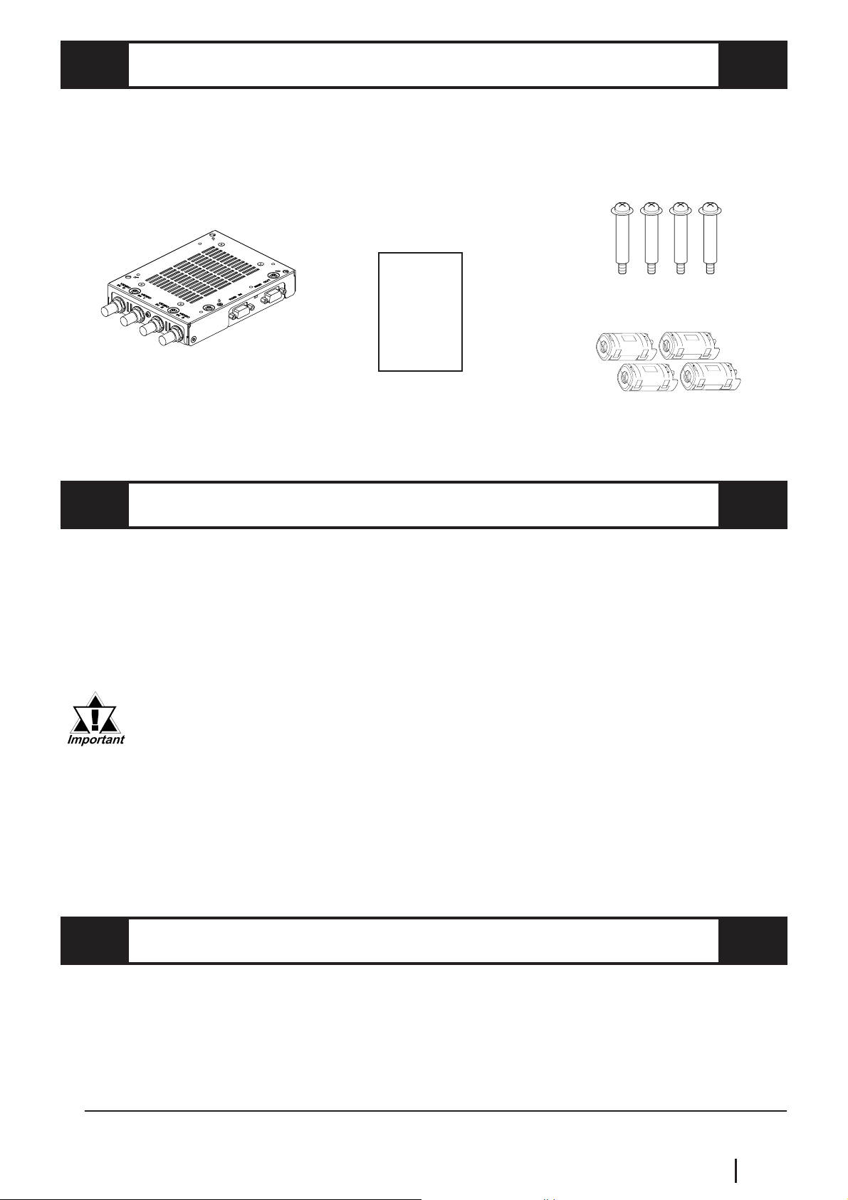
The VM Unit's packing box contains the items listed below. Please check to confirm
that all items shown below have been included.
VM Unit
(GP2000-VM41)
Unit User Manual
Attachment Screws (4) GP2000 Series VM
(this manual)
GP2000 Series
VM Unit
User Manual
Ferrite Cores (4)
This unit has been carefully packed with special attention to quality. However, should you
find anything damaged or missing, please contact your local distributor immediately.
APPLICABLE PRODUCTS
The following GP units and screen software are used with the VM Unit.
GP Units
GP-2500 Series, GP-2600 Series and GLC2600 Series
Screen Editor Software
GP-PRO/PB III for Windows Ver. 5.05 or higher
*1
GP-PRO/PBIII for Windows Ver. 5.05 or higher is required to utilize the
VM unit's full range of features. If you are currently using a version of
GP/PRO that is earlier than 5.05, you will need to upgrade your software
to version 5.05. For purchasing information, please contact your local
Pro-face distributor.
Version 5.0 users can display their standard GP screen and a single
video window. However, the display of multiple video screens and saving
of JPEG screen capture images is not possible.
OPTIONAL ITEMS
The following cables are sold separately for the VM Unit.
RGB Cables
FP-CV00 (2.5 m)
FP-CV01 (5.0 m)
*1 GP-PRO/PBIII version information can be found in the Project Manager screen's Help pull-
down menu's Version Information selection.
GP2000 Series VM Unit User Manual
E5
Page 7
RELATED MANUALS
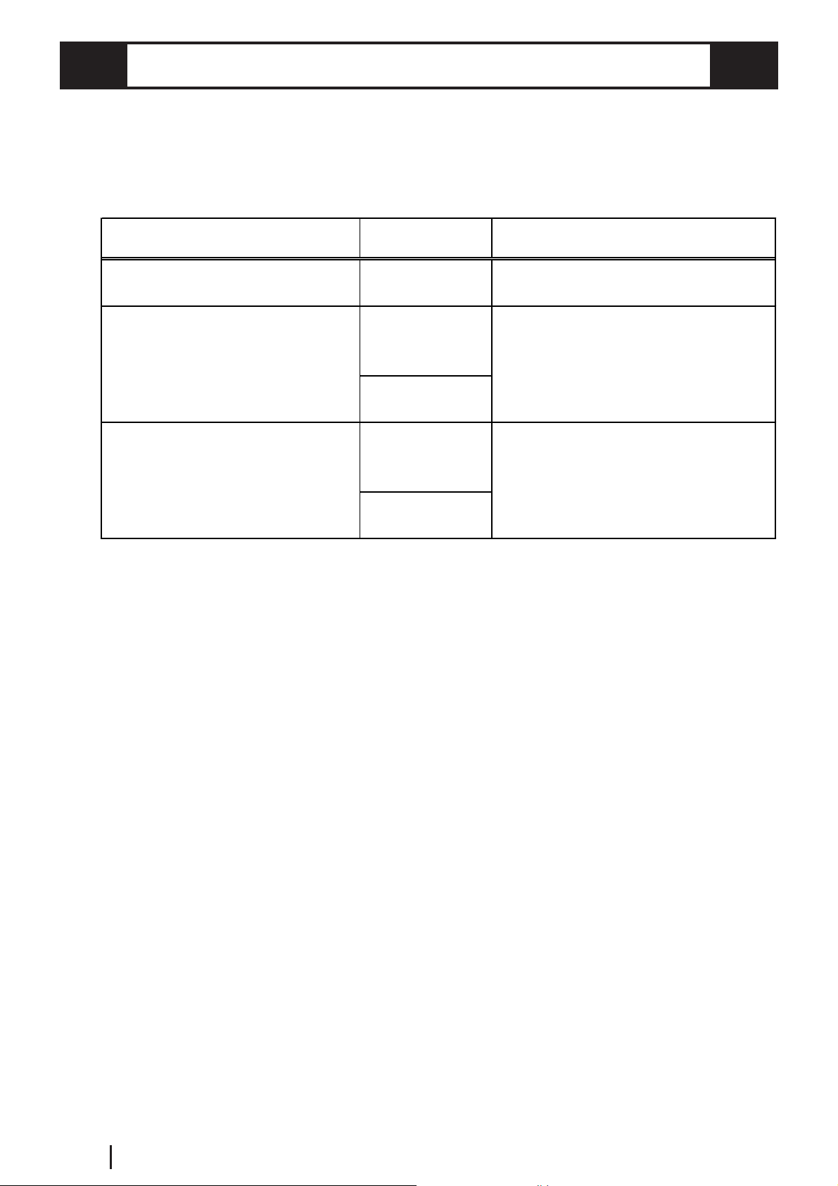
The following table explains additional reference information resources (available as
PDF and printed manuals) that are useful when operating the VM Unit. Depending on
your VM Unit application, a number of different manuals may be required. Be sure to
refer to the appropriate reference information prior to operating the VM Unit.
Type of VM Unit Information Forma t Manual Name
Covers GP2000 unit se t up and ope ration
Contains v-tag and video window set up
information.
Contains s creen creation so f tware
operat ion and P a rt usage information.
Paper Manual
(sold sep arat e ly)
PDF file
(included with
GP-PRO/PBIII)
Paper Manual
(sold sep arat e ly)
PDF file
(included with
GP-PRO/PBIII)
Paper Manual
(sold sep arat e ly)
GP2000 Ser ies Us er Manual
GP-P RO/ P B I II for Windows Tag Reference
Manual
GP-P RO/ P B I II for Windows Oper at ion Manual
E6
GP2000 Series VM Unit User Manual
Page 8

UL/c-UL (CSA) APPLICATION
The GP2000-VM41 is a UL/c-UL (CSA) listed product. (UL file No.E182139)
This unit conforms as a product to the following standards:
UL508 Industrial Control Equipment
UL1604 Electrical Equipment for use in Class 1 & 2 - Division 2,
or Class 3 Hazardous Locations.
CAN/CSA-C22.2, Nos 142, and 213-M1987
Standard for Safety of Information Technology Equipment, including Electrical Business Equipment
GP2000-VM41 (UL Registration Model: 2980020-01)
<Cautions>
• The VM must be used as a built-in component of a GP unit.
• If this unit is installed so as to cool itself naturally, be sure to attach the VM to a
GP unit that is installed in a vertical panel. Also, be sure that the GP unit is
mounted at least 100 mm away from any adjacent structures or equipment. If these
requirements are not met, the heat generated by the GP unit’s internal components
or the VM Unit may cause the combination to fail to meet UL/c-UL standard requirements.
UL1604 Conditions of Acceptability and Handling Cautions:
1. Power, input and output (I/O) wiring must be in accordance with Class I, Division
2 wiring methods - Article 501- 4(b) of the National Electrical Code, NFPA 70
within the United States, and in accordance with Section 18-152 of the Canadian
Electrical Code for units installed within Canada.
2. Suitable for use in Class I, Division 2, Groups A, B, C and D, Hazardous Locations.
3. WARNING: Explosion hazard - substitution of components may impair suitability
for Class I, Division 2.
4. WARNING: Explosion hazard - when in hazardous locations, turn power OFF
before replacing or wiring modules.
5. WARNING: Explosion hazard - do not disconnect equipment unless power has
been switched OFF, or the area is known to be non-hazardous.
CE MARKING
The GP2000-VM41 is a CE marked product that conforms to EMC directives
EN55011 class A and EN61000-6-2.
This marking requires the attachment of a Ferrite Core (included) to each video
cable used.
* For detailed CE marking information, please contact your local GP distributor.
GP2000 Series VM Unit User Manual
E7
Page 9
DOCUMENTATION CONVENTIONS
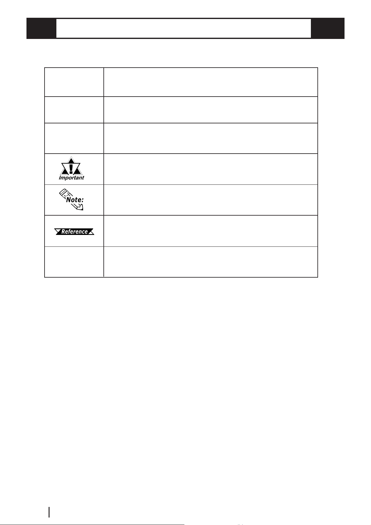
The list below describes the documentation conventions used in this manual.
GP
Screen editor
software
*1
1., 2., ...
Indicates the GP2000 Series Graphical Operator Interfaces
Indicates the GP-PRO/PB III for Windows screen editor software
Indicates words and phrases explained in footnotes.
Indicates important information or procedures that must be
followed to prevent VM Unit operation or data-related
problems
Provides useful or important supplemental information.
Indicates a page or material containing reference information.
Indicates steps in a procedure. Be sure to perform these
steps in the order given.
E8
GP2000 Series VM Unit User Manual
Page 10
Chapter 1 : OVERVIEW
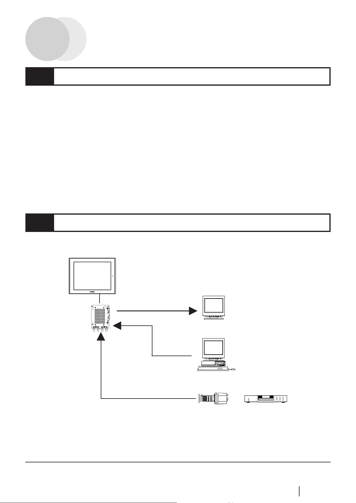
1.1 VM Unit Features
The VM Unit allows you to display images from external video cameras or from a PC
on the GP screen. You can also use the VM Unit to output GP screen images to other
devices.
• External Video Camera (VIDEO) input is supplied via four (4) connectors, and PC
monitor (RGB) input is via a single D-sub connector, for a total of five inputs.
These inputs can be used to create up to four (4) video displays on your GP screen.
• The VM Unit provides the GP with a single video (RGB) output, which allows the
display of GP screen images on a PC monitor.
• GP screen data can also be captured, converted to a JPEG file and saved to a CF
Card. JPEG images on a CF Card can also be read in by the GP and displayed.
1.2 System Design
The following diagram represents the connection example.
GP
(1)
(2)
VM Unit
*1
(3)
Monitor, Projector, etc.
(4)
Personal Computer
Video Camera, VCR, Tuner, etc.
(1) VM BUS: Connects to the GP rear face Expansion Unit's EXT2 I/F.
(2) RGB OUT: Uses an RGB cable.
(3) RGB IN: Uses an RGB cable.
(4) VIDEO IN (0 to 3): Uses a video cable.
*1 When the VM Unit is installed in the GP, the Bus Conversion Unit (PSL-
CONV00) cannot be used.
GP2000 Series VM Unit User Manual
E1-1
Page 11
1.3 Using the Screen Editor Software
When specifying the GP type in the screen editor software, select "GP2500",
"GP2500S", "GP2600" or "GLC2600" on your GP/GLC. For selection details,
GP-PRO/PB III for Windows Operation Manual (Included with the
screen editor software)
• To use all the VM Unit's features, GP-PRO/PB III for Windows Ver.
*1
5.05
of this software, you will need to upgrade to 5.05. For information,
contact your local Pro-face distributor.
• Version 5.0 users can display their standard GP screen and a single
video window. However, the display of multiple video screens and
saving of JPEG screen capture images is not possible.
or higher is required. If you are currently using an earlier version
*1 GP-PRO/PBIII version information can be found in the Project Manager screen's Help pull-
down menu's Version Information selection.
E1-2
GP2000 Series VM Unit User Manual
Page 12
Chapter 2 : SPECIFICATIONS
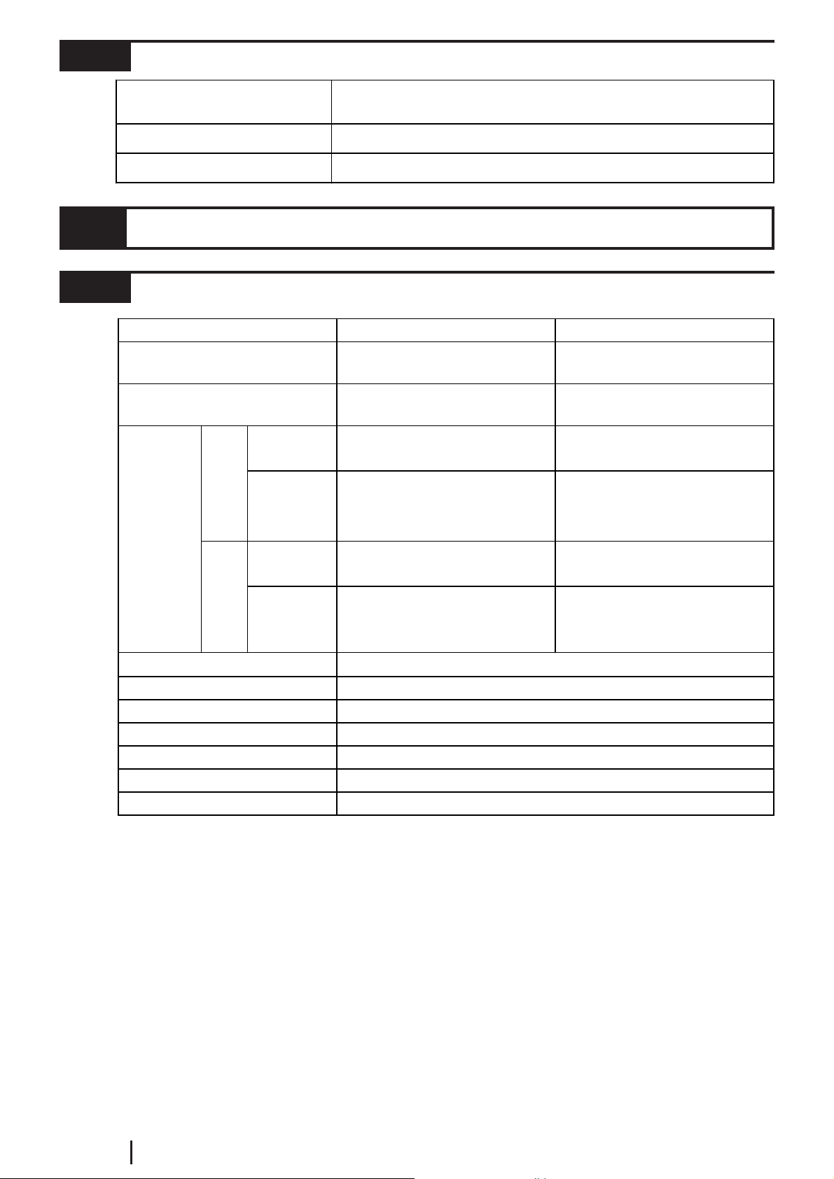
(
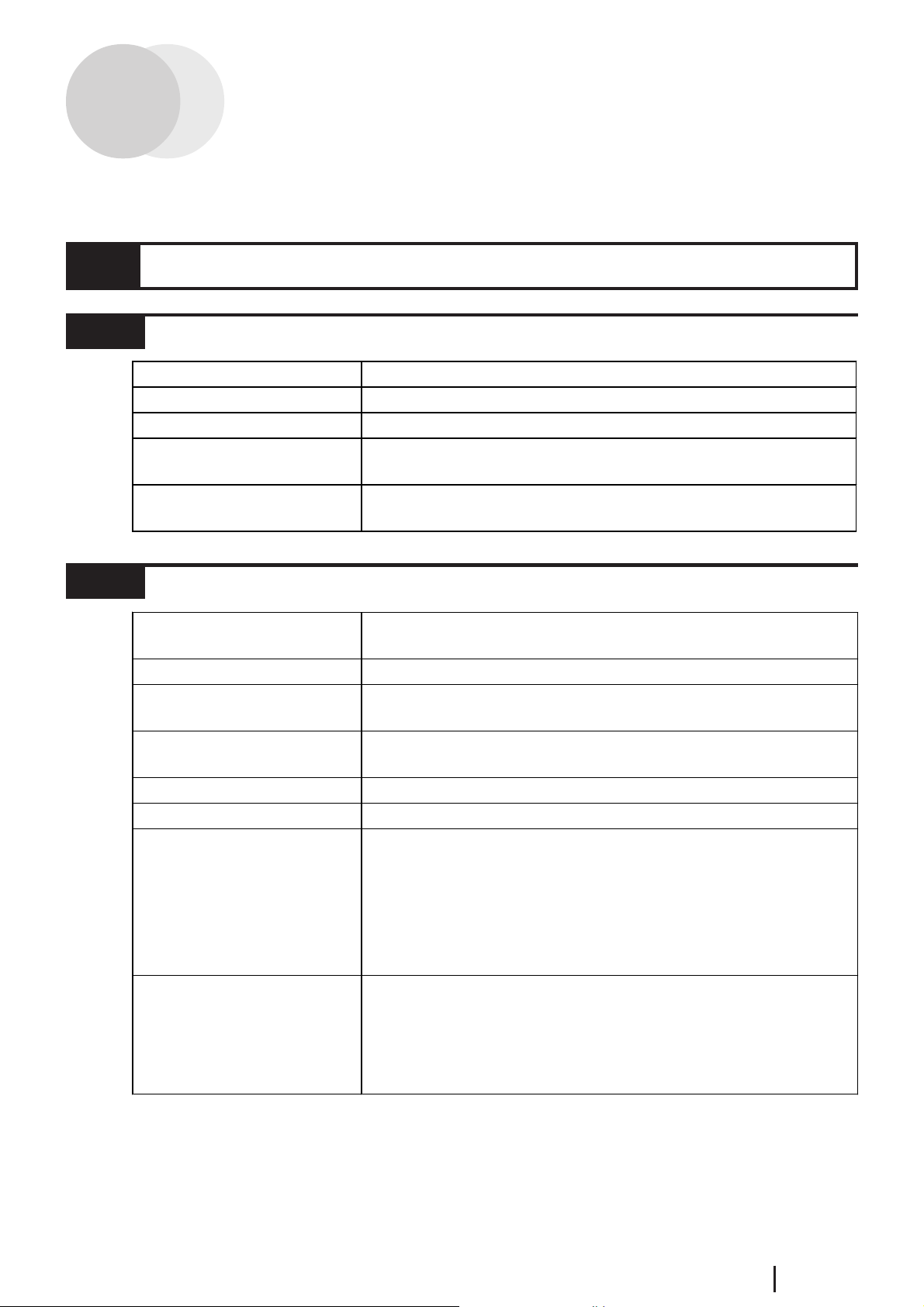
2.1 General Specifications
2.1.1 Electrical
Rat ed Vo lt ag e
Al l owable Voltage Range
Current Consumpt i on
Insul a tion Endurance
Insulat i on Resistance
2.1.2 Environmental
Am bient O perat i ng
Temperature
Storage Temperature
Ambient Humidity
Storage Humidit y
Dust
Atmosphere
Vibrati on Resistance
Noise Imm unit y
(via noise simulator)
DC5V (Supplied from the GP Unit)
DC4. 7 5 V to DC5.25 V
approx. 1.1 A
AC1500V, 20 mA for up to 1 minute
(betwe en GP unit c harging and F G te rm i nals)
10 MΩ or more at DC500V
(betwe en GP unit c harging and F G te rm i nals)
0°C to +50°C
-20°C to +60°C
10% RH to 90% RH
non-condensing, we t bulb te mperature: 39°C or less)
10% RH to 90% RH
(non-condensing, wet bulb temperature: 39°C or less)
0.1 mg/m3 or less (Non-conductive levels)
Free of corrosive gasses
IEC61131-2 compatible
When vibration i s NOT co ntinuous :
When vibration i s c ontinuous :
X, Y, Z d i rectio ns fo r 10 times (80 mi n.)
Noise Voltage:
Pulse Duration:
Rise Ti m e:
(via nois e s imulator)
*1
*1
10 Hz to 57 Hz : 0. 075 mm ,
57 Hz to 150 Hz : 9.8 m /s
10 Hz to 57 Hz : 0. 035 mm ,
57 Hz to 150 Hz : 4.9 m /s
1500 Vp-p (100 V AC p ower s uppl y
1000 Vp-p (24 V DC powe r sup ply )
1 µs
1 ns
2
2
*1 Must be within the GP unit's ambient temperature/humidity range.
GP2000 Series VM Unit User Manual
E2-1
Page 13
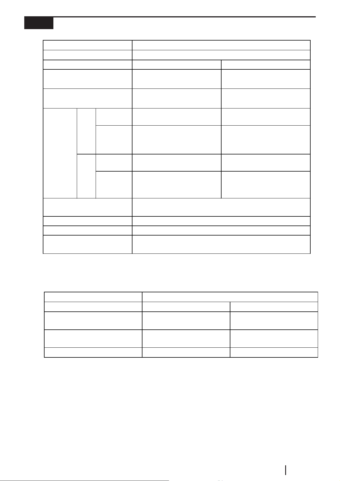
2.1.3 Structural
y
y
External Dimensions
Weight
Cooling Method
W110mm [ 4.33in] x H146mm [5. 75in] x D27mm [1. 06i n]
(Excluding projections)
Approx . 560g [1. 23l b] (m ai n uni t o nl y)
Natural ai r circul a tion
2.2 Functional Specifications
2.2.1 Video Display
Signal System
Hori zont al Sync hr onou s
Frequenc
Verti c al Synchronous
Frequenc
GP-
2500
Max.
Display
Size
No. of Input Channels
No. of Vi deo Scr eens
Bright ness Cont ro l
Cont rast Con tr ol
Special Funct i ons
GP-
2600
/
GLC
2600
Colors
Col or Contr ol
*1
Compatible
Mode
Extend
Mode
Compatible
Mode
Extend
Mode
15.734kHz 15.625kHz
320 x 240 dots (Normal)
640 x 480 dots (Zoom )
640 x 480 dots (Normal)
320 x 240 dots (1/4 mode)
160 x 120 dots (1/16 mode)
320 x 240 dots (Normal)
640 x 480 dots (Zoom )
640 x 480 dots (Normal)
320 x 240 dots (1/4 mode)
160 x 120 dots (1/16 mode)
32,768 / 64 l evels of mono chrome (grayscale)
16 le vel s of adjustment available fo r each c hannel
16 le vel s of adjustment available fo r each c hannel
16 le vel s of adjustment available fo r each c hannel
Still (Still-frame video image), Transparent color setting, Zoom
*2
NTSC
59.9Hz 50Hz
up to 4 (Extended Mode)
PAL
320 x 240 dots (Normal)
640 x 480 dots (Zoom)
640 x 480 dots (Normal)
320 x 240 dots (1/4 mode)
160 x 120 dots (1/16 mode)
384 x 288 dots (Normal)
768 x 576 dots (Zoom )
768 x 576 dots (Normal)
384 x 288 dots (1/4 mode)
192 x 144 dots (1/16 mode)
4
*3
*3
E2-2
*1 A single VM Unit can use only one signal system.
*2 NTSC 4.43 is not supported.
*3 A portion of the 768 x 576 dot (pixel) screen will not be displayed.
GP2000 Series VM Unit User Manual
Page 14
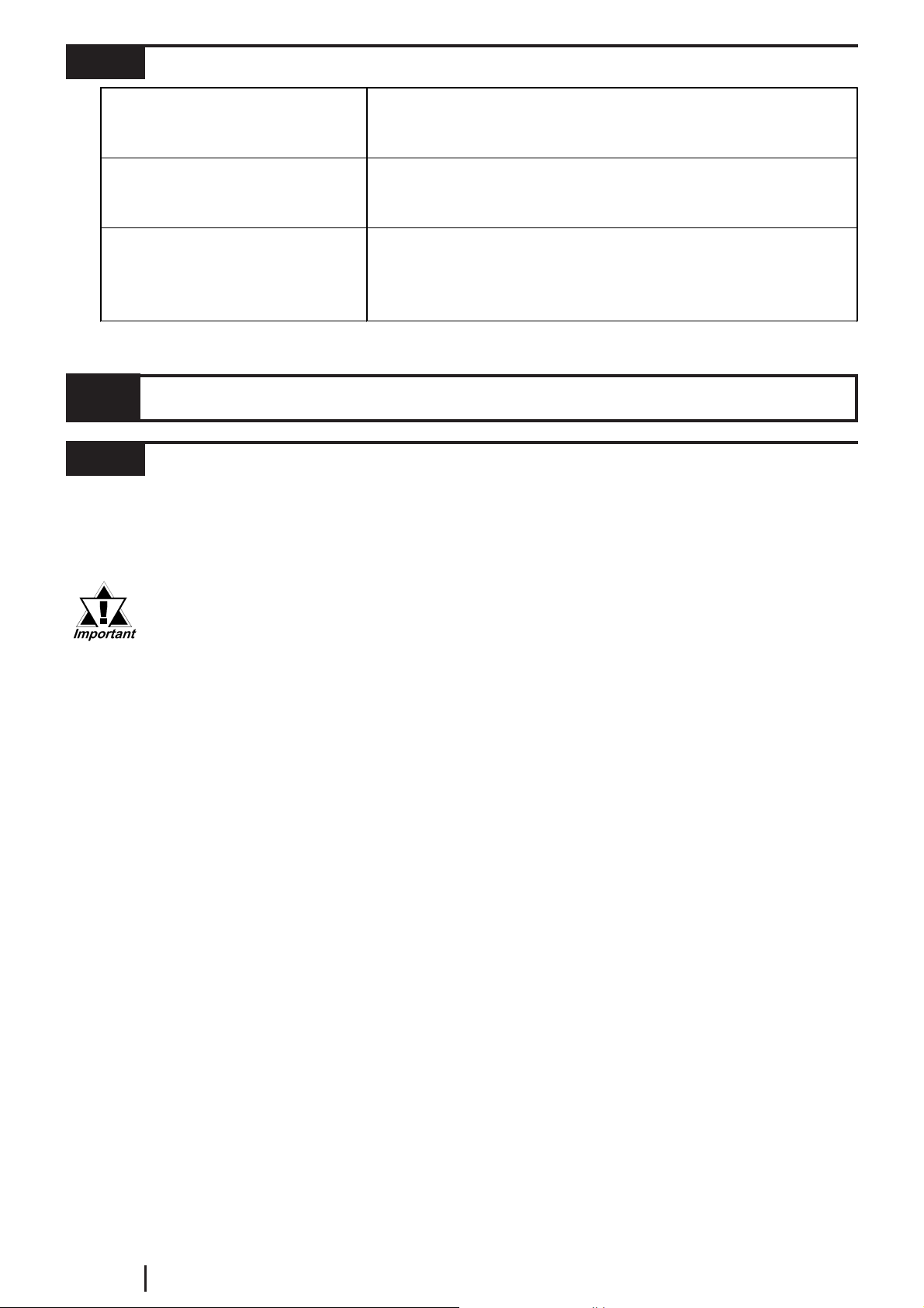
2.2.2 VGA/SVGA Display
RGB Input
Colors
In put Signal System
Display Mode
32,768
Analog RGB
VGA SVGA
Hori zont al Sync hr onou s
Frequency
Verti c al Synchronous
Frequency
Compatible
GP-
2500
Max.
Display
Size
Posit i on Adjustment
Clock Adjust ment
Phase Adjustment
Color Adjustment
GP-
2600
/
GLC
2600
Mode
Extend
Mode
Compatible
Mode
Extend
Mode
31.4 kHz to 43.3 kHz 35.1 kHz to 46.9 kHz
59.0 Hz to 85.1 Hz 56.0 Hz to 75.0 Hz
640 x 480 dots
640 x 480 dots (Normal)
320 x 240 dots (1/4 mode)
160 x 120 dots (1/16 mode)
800 x 600 dots
640 x 480 dots (Normal)
320 x 240 dots (1/4 mode)
160 x 120 dots (1/16 mode)
4 le vel s of adj ustment and 256 l evels of fine adj us tment av ai l able for
*3
Horizontal:
Vertical:
red, green and blue
-128 to 128 d ots
-16 to 16 dots
-128 to 1 28
64 lev els
640 x 480 dots
640 x 480 dots (Normal)
320 x 240 dots (1/4 mode)
160 x 120 dots (1/16 mode)
800 x 600 dots
800 x 600 dots (Normal)
400 x 300 dots (1/4 mode)
200 x 150 dots (1/16 mode)
*1
*2
*1 Selecting SVGA compresses an 800 x 600 dot screen to 640 x 480 dots.
*2 A portion of the screen will not be displayed.
*3 Selecting VGA expands a 640 x 480 dot screen to 800 x 600 dots.
RGB Output
Output Si gnal syst em
GP Type
Horizontal Synchr oni zati on
Frequency
Vertical Sy nc hr onizati o n
Frequency
Output Size
GP-2500
30.20 k Hz 35. 75 kHz
58.19 Hz 56.93 Hz
640 x 480 dots 800 x 600 dots
Analog RGB
GP-2600 / GLC2600
GP2000 Series VM Unit User Manual
E2-3
Page 15
2.2.3 External Interface
)
)
)
Video I nput
RG B Input
RG B Out p ut
Input specifications:
No. of interfaces:
Connector:
Input specifications:
No. of interfaces:
Connector:
Output speci fic ations:
No. of interfaces:
Connector:
NTSC/PAL system
4
75 Ω BNC (Receptacle
VGA/SVGA
1
D-sub 15 pin (Socket
640 x 480 dots (GP-2500)
800 x 600 dots (GP-2600/GLC2600)
1
D-sub 15 pin (Socket
2.3 Interface Specifications
2.3.1 Video Input Interface
Video cameras, VCRs, or tuners can be connected to this NTSC/PAL system interface.
Input Amplitude: 1 Vp-p: 75 Ω (Composite video signal)
Recommended Connector: BNC-P-3DV-SA <made by HIROSE DENKI>
Recommended Cable: 3C-2V Coaxial cable
• You cannot connect NTSC and PAL systems simultaneously.
• NTSC 4.43 is not supported.
E2-4
GP2000 Series VM Unit User Manual
Page 16
2.3.2 RGB Input and Output Interfaces
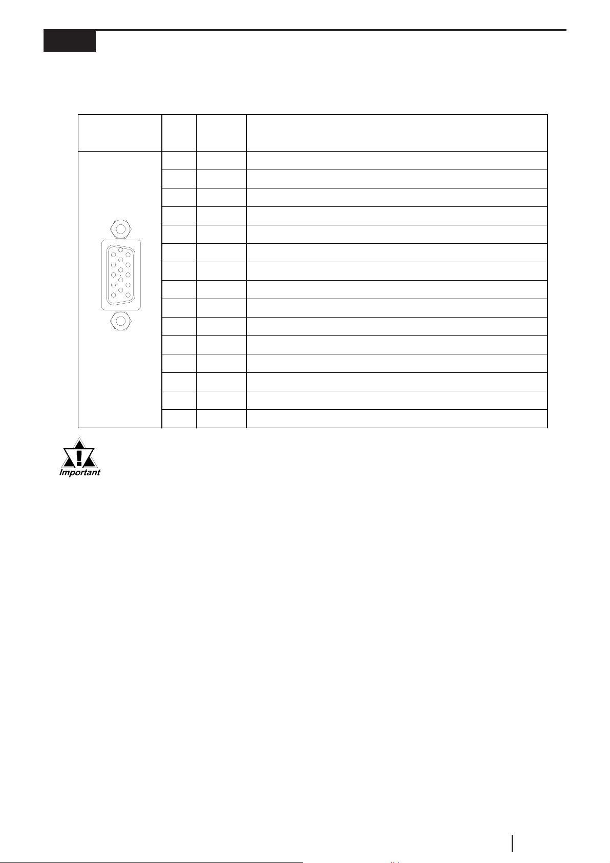
The VM Unit features one interface for RGB input and one for RGB output.
®
You can connect a Windows
You can connect a monitor or a projector to the RGB output interface.
PC or other devices to the RGB Input Interface.
Pin
Assignments
Dsub 15-pin
Male
1
5
11
15
Pin #
Signal
Name
1 RED Red signal input (output), Analog, Positive (0.7Vp-p: 75Ω)
2 GREEN Green signal input (output), Analog, Positive (0.7Vp-p: 75Ω)
3 BLUE Blue signal input (output), Analog, Positive (0.7Vp-p: 75Ω)
4 NC No connec tion
5 NC No connec tion
6 RRED Return ground for red signal
7 RGREEN Return ground for green signal
8 RBLUE Return ground for blue signal
9 NC No connec tion
10 GND Ground
11 NC No connec tion
12 NC No connec tion
13 HD Hori zontal s y nchronization s i gnal (TTL Pos i tive/ negative)
14 VD Vertical synchronization signal (TTL Positive/negative)
15 NC No connec tion
Condition
• Be sure to use a straight cable that complies with VGA Impedance
Standards.
Recommended connector (plug): XM4K-1543 <made by OMRON>
Recommended cover: XM2S-0913 <made by OMRON>
Recommended RGB cables (with connectors at both ends)
: FP-CV00 (2.5m) <made by Digital Electronics Corporation>
FP-CV01 (5.0m) <made by Digital Electronics Corporation>
• Connect the cables before starting up the PC/monitor and the GP. To
prevent a possible equipment malfunction, do not disconnect the cable
while the equipment is turned ON.
• The RGB input and output connectors have similar shapes. Confirm
that the connector is correct before attaching it.
• Be sure to design your system so that length of the RGB Output cable
does not exceed 5 meters.
GP2000 Series VM Unit User Manual
E2-5
Page 17
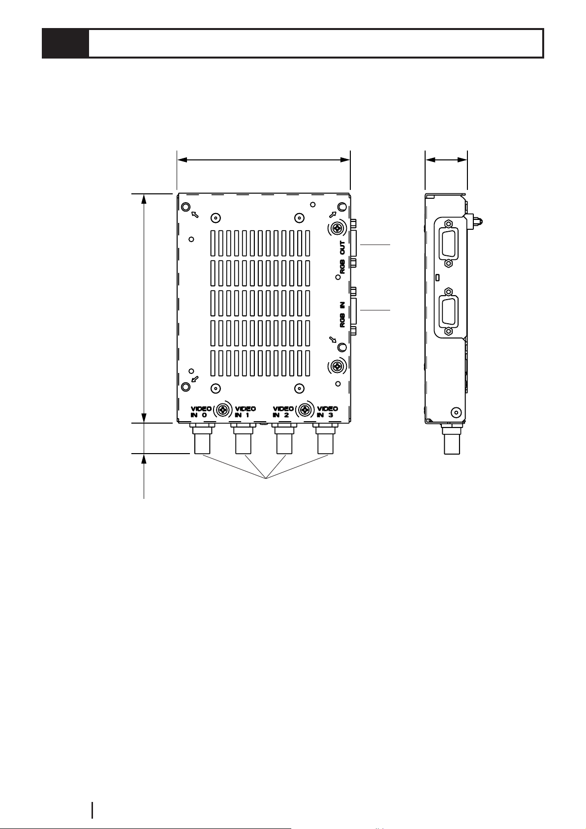
2.4 Part Names and Functions
Units : mm [in.]
146 [5.75]
110 [4.33]
27 [1.06]
A
B
(19 [0.75])
A: RGB OUT
RGB Output Connector
B: RGB IN
RGB Input Connector
C: VIDEO IN 0 to 3
Video Input Connectors
C
E2-6
GP2000 Series VM Unit User Manual
Page 18
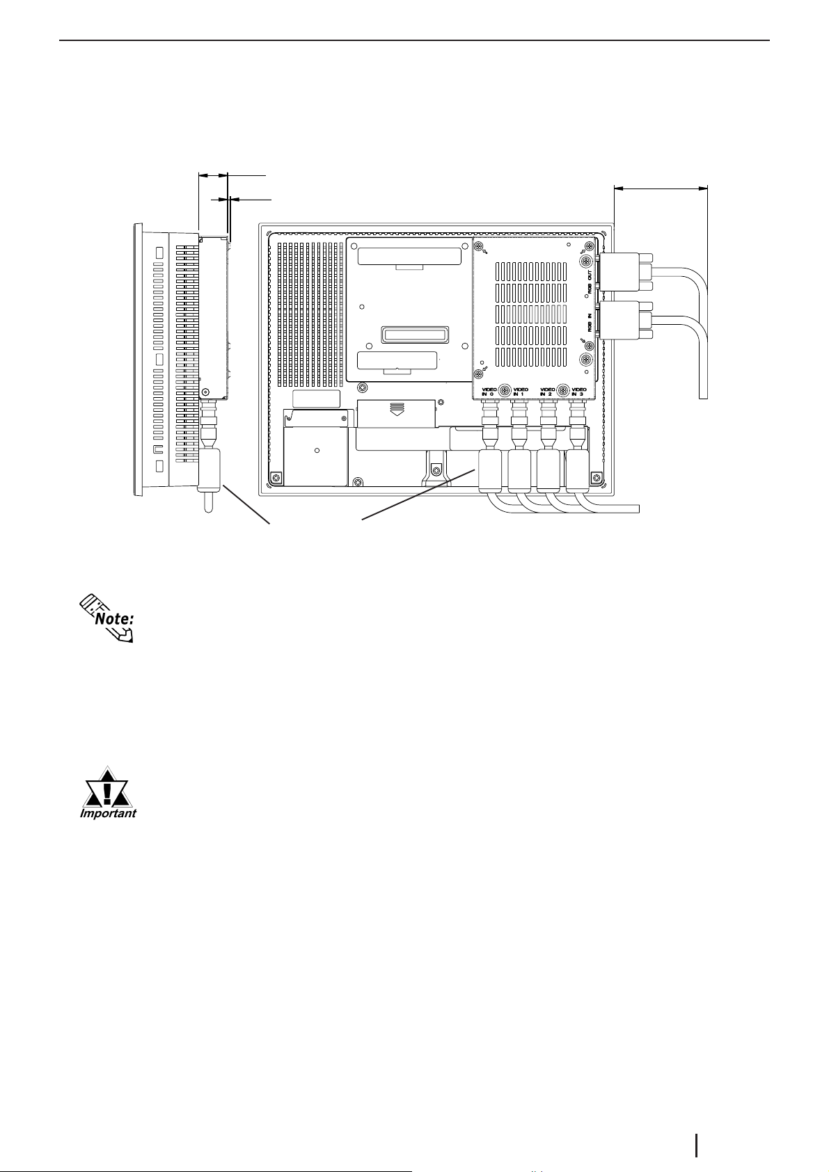
The following external dimensions are for a VM Unit that is attached to a GP2000
series unit.
Unit : mm [in.]
26 [1.02]
3 [0.12]
100 [3.94]
Ferrite Cores
• The length given here for the RGB cable's protrusion from the VM Unit is
when the recommended cables (FP-CV00 or FP-CV01 <made by Digital Electronics Corporation>) are used.
• The maximum bendable radius of the video cable varies depending on the type
of cable used. Check the cable specifications prior to installation.
• CE Marking regulations require the attachment of a Ferrite Core (included) to
each video cable used.
• Be sure to design your system so that after the GP unit is installed
there is sufficient space for the VM Unit's connectors and cable routing.
• When installing the cable, be sure to consider the cable material and
the amount of force to be put on the cable.
• When installing or removing the GP unit while its connectors attached,
be sure not to damage any of the connectors.
GP2000 Series VM Unit User Manual
E2-7
Page 19

Memo
E2-8
GP2000 Series VM Unit User Manual
Page 20
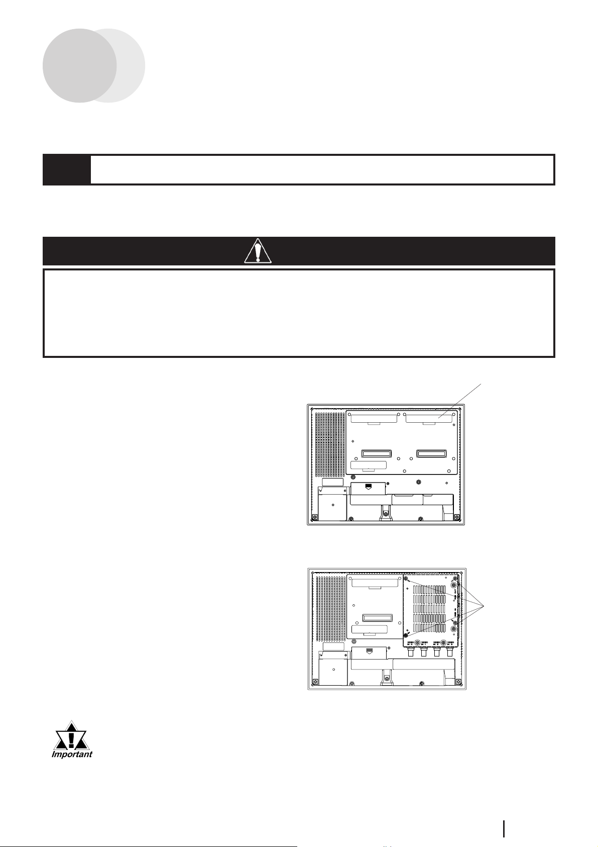
Chapter 3 : INSTALLATION AND WIRING
3.1 Installing the VM Unit
Install the VM Unit in the GP using the following steps.
WARNINGS
• To prevent an electric shock, prior to the installation be sure to check
that the GP and VM Units are not connected to a power supply.
• Do not touch the circuit board mounted on the inner face of the VM
Unit.
1. Unplug GP unit's power cord .
2. Remove the rear face connector
cover attached to Expansion Unit
I/F 2 (EXT2).
3. Carefully insert the VM Unit into
the GP until the GP and VM Unit
connectors are securely attached.
4. Use a screwdriver to attach each of
the VM Unit's attachment screws.
(Screws are provided with VM
Unit)
Connector Cover
Rear Face of GP
Attachment
Screws
Tightening torque: 0.5 to 0.6 N•m
When installing/removing the VM Unit, be careful not to lose the attachment screws.
GP2000 Series VM Unit User Manual
E3-1
Page 21
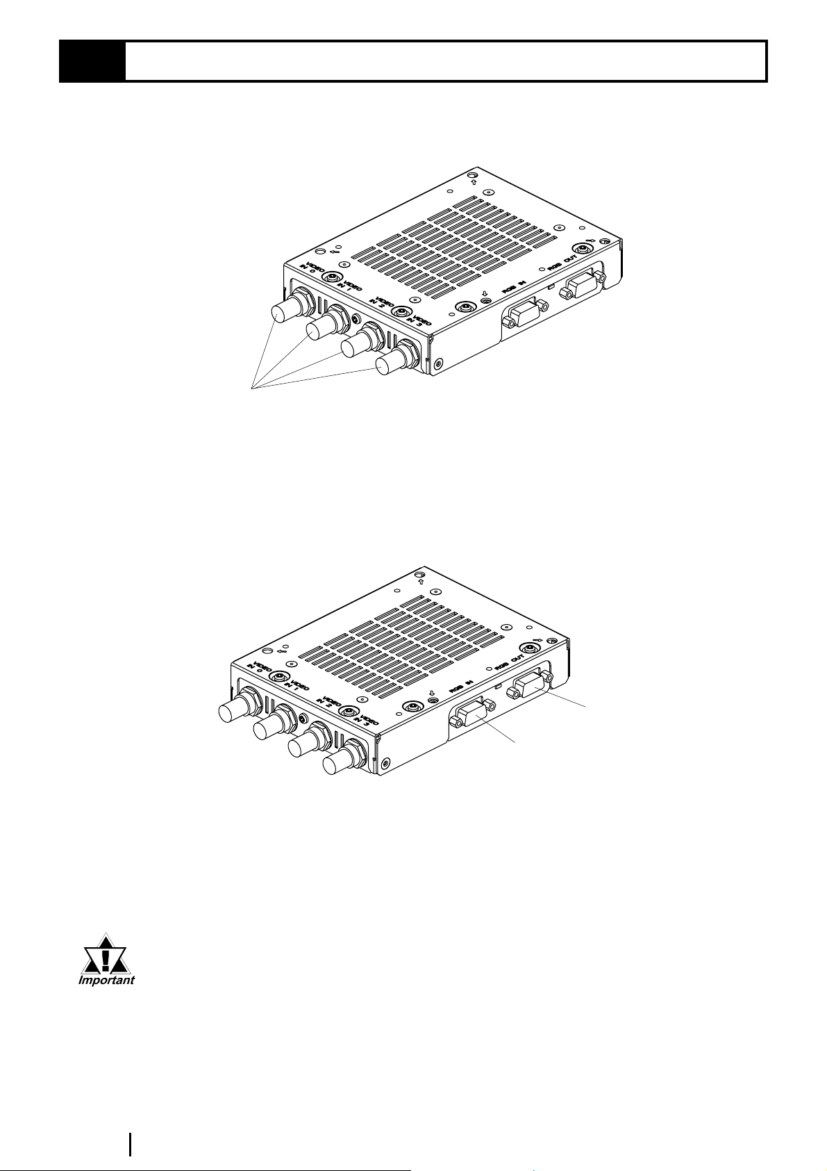
3.2 Cable Connection
Connecting a Video Cable
Connect a BNC connector to one of the VIDEO IN 0 to 3 connectors. Turn the BNC
connector one-quarter turn to lock it in place.
VIDEO IN 0 to 3
Recommended Connector: BNC-P-3DV-SA <made by HIROSE DENKI>
Recommended Cable : 3C-2V Coaxial cable
Connecting an RGB Cable
Connect a D-sub 15 pin connector to either of RGB OUT or RGB IN. Secure the
connector in place with its attachment screws. (left and right side)
RGB OUT
RGB IN
Recommended connector : XM4K-1543 <made by OMRON>
Recommended cover : XM2S-0913 <made by OMRON>
Recommended RGB cable (with connectors at both ends)
:FP-CV00 (2.5m) <made by Digital Electronics Corporation>
E3-2
FP-CV01 (5.0m) <made by Digital Electronics Corporation>
• Connect the cables before starting up the PC/monitor and the GP. To
prevent a possible equipment malfunction, do not disconnect the cable
while the equipment is turned ON.
• The RGB input and output connectors have similar shapes. Confirm
that the connector is correct before attaching it.
• Be sure to design your system so that length of the RGB Output cable
does not exceed 5 meters.
GP2000 Series VM Unit User Manual
Page 22
Chapter 4 : SETUP
This chapter describes how to set up the VM Unit.
4.1 Video Window Adjustment
This section describes how to adjust the images received from the VIDEO IN cable.
First, switch your GP unit to OFFLINE mode. For OFFLINE mode details , refer to
"GP2000 Series User Manual" (sold separately).
You can also adjust your VM Unit via the GP System Setup area in the screen editor
software.
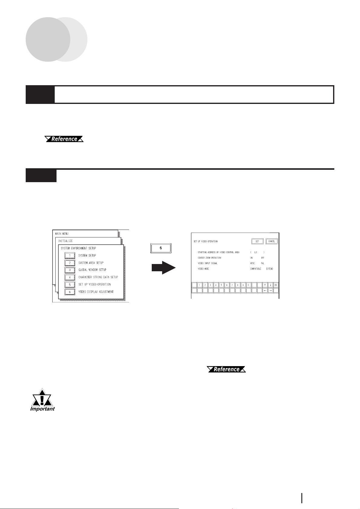
4.1.1 SET UP VIDEO OPERATION
Here, you can enter the parameters that control the display of your video signal.
To display the setup screen, select the "INITIALIZE", "SYSTEM ENVIRONMENT
SETUP" and "VIDEO DISPLAY ADJUSTMENT" screens. (The SETUP VIDEO
OPERATION screen will appear only when the VM Unit is installed.)
STARTING ADDRESS OF VIDEO CONTROL AREA
In the GP's LS area, you can designate "LS0020" through "LS2010" as the starting
address of the video control area. After the starting address is specified, in "COMPAT-
IBLE" mode 22 continuous words (in "EXTEND" mode 43 continuous words), beginning from the starting address are assigned as the video control area. Designating
"LS0000" as the starting address disables the VM Unit feature.
For the details of the video control area, refer to "GP-PRO/PB III for
Windows Tag Reference Manual" (included with the screen editor software).
When converting GP-530VM unit screens to GP2000 unit data, be aware
that the starting address of the video control area will be different.
CENTER ZOOM OPERATION (only when Video Mode is set to COMPATIBLE")
This setting designates whether to enable or disable the center zoom feature.
When the center zoom feature is enabled, the center of the video image is magnified
when normal mode is switched to zoom mode. When the feature is disabled, the image is magnified by setting the video display origin point (specified in the video
control area) at the center of the GP unit's screen.
GP2000 Series VM Unit User Manual
E4-1
Page 23
VIDEO INPUT SIGNAL
Select from "NTSC" or "PAL".
VIDEO MODE
Select from "COMPATIBLE" (with GP-570VM), and "EXTEND".
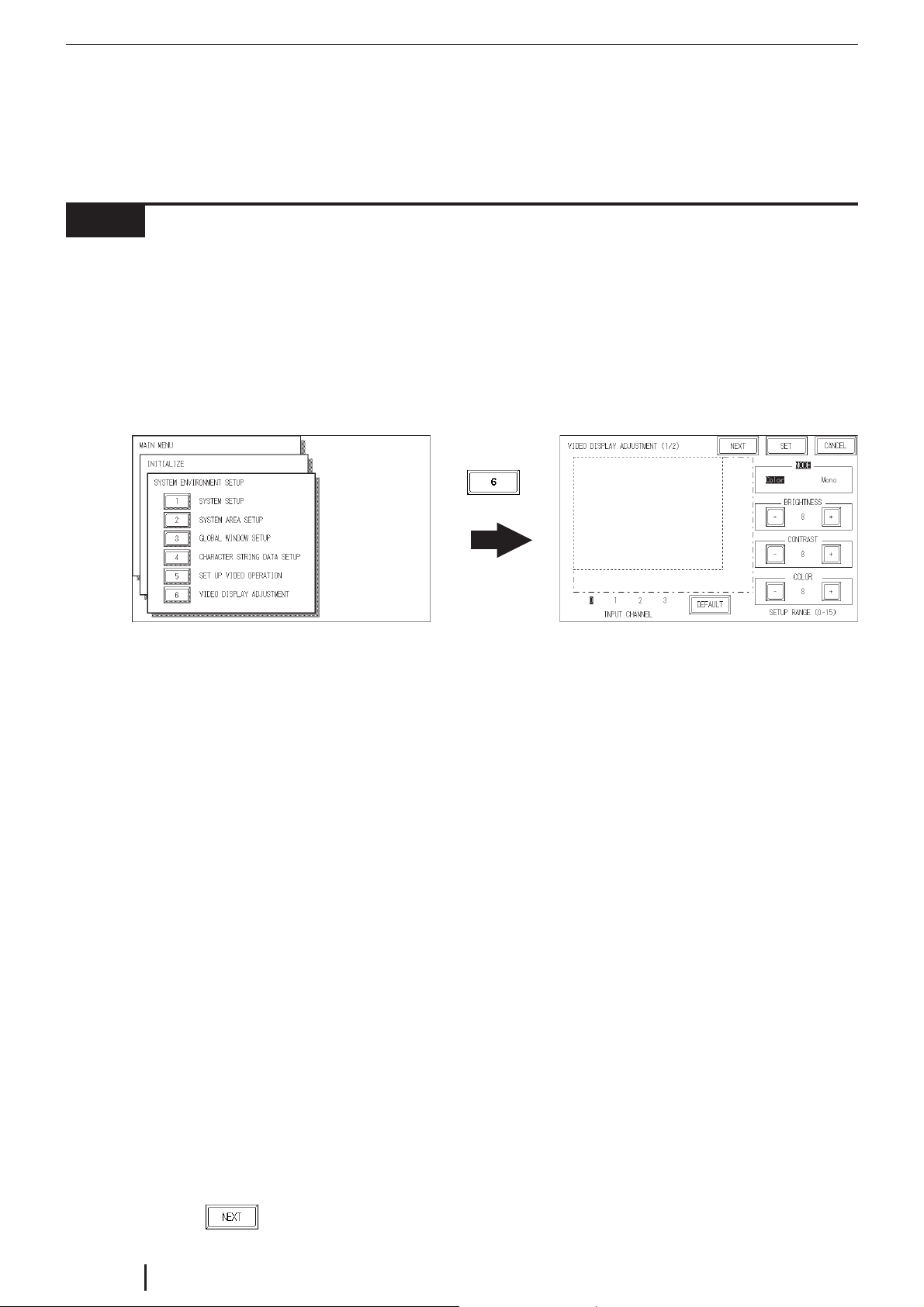
4.1.2 VIDEO DISPLAY ADJUSTMENT
This setting allows you to adjust the video image display quality.
To display the setting screen, select the "INITIALIZE", "SYSTEM ENVIRONMENT
SETUP" and "VIDEO DISPLAY ADJUSTMENT" screens. (This menu is displayed
only when the VM Unit is installed.)
The current video image appears on the left of the screen. You can adjust the screen
while viewing the actual display.
VIDEO DISPLAY ADJUSTMENT (1/4)
INPUT CHANNEL
Select video device's input channel (VIDEO IN 0 through 3).
MODE
Select whether the input from the video device is color or monochrome. Designate
this setting for each input channel used.
BRIGHTNESS
Adjust the brightness of the video window. Designate this setting for each input
channel used.
CONTRAST
Adjust the contrast of the video window. Designate this setting for each input channel
used.
COLOR
Adjust the color of the video window. Designate this setting for each input channel
used. This setting is disabled when "MODE" is set to "Mono".
DEFAULT
Resets "BRIGHTNESS", "CONTRAST" and "COLOR" to the middle value "8".
Touch the
E4-2
key to display the next screen.
GP2000 Series VM Unit User Manual
Page 24
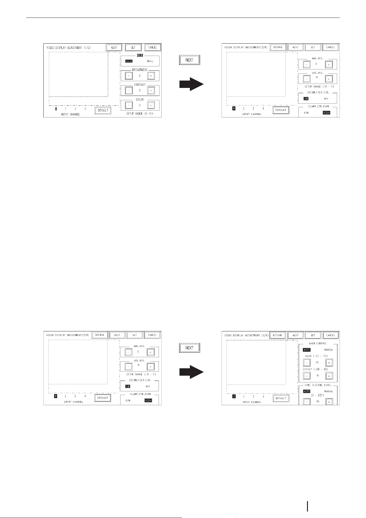
VIDEO DISPLAY ADJUSTMENT (2/4)
HOR. POS.
Allows horizontal adjustment of the video input signal. However, since this setting is
applied to all VM channels, channels cannot be set individually.
VER. POS.
Occasionally, the video signal's standard vertical positioning can differ slightly from
the image's actual vertical positioning. When all image screens are used, this can
result in cropping of the top or bottom of the screen, or display of screens other than
the valid display area. This feature is designed to correct this problem.
DECIM. FILT. CIR.
Turns ON and OFF the decimeter circuit built into the decoder. When mono chrome
signals are being received, disabling the signal processing filter (decimeter) circuit
may result in finer image quality. In normal operations, leave the setting at ON.
CLAMP. CIR. CURR
Turns ON and OFF the decimeter circuit built into the decoder. When mono chrome
signals are being received, disabling the signal processing filter (decimeter) circuit
may result in finer image quality. In normal operations, leave the setting at ON.
VIDEO DISPLAY ADJUSTMENT (3/4)
GAIN CONTROL
Perform gain control for the digital amplifier circuit.
Automatic: Automatically adjusts the gain (amplification factor) and offset (black
level) according to the input signal level.
Manual: Permits adjustment of the gain (amplification factor) and offset (black level)
to desired values.
GP2000 Series VM Unit User Manual
E4-3
Page 25
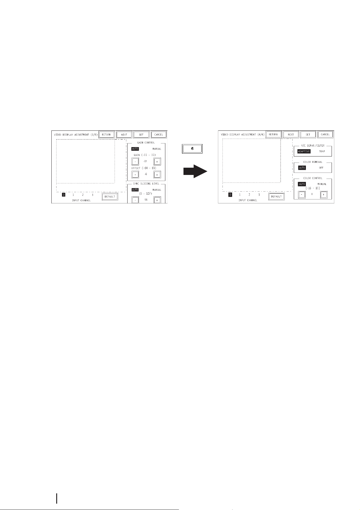
SYNC SLICING LEVEL
Set the depth of the level for detecting the synchronization signal. If the synchronization signal depth of the video signal is shallower than the standard, or if the depth
varies, the synchronization signal will not be detected. This condition will result in
horizontal or vertical blurring of the screen. When this symptom occurs, adjusting
the detection level may stabilize the blurred screens. In normal operation, leave the
setting at Automatic mode. If screen blurring occurs, changing the setting to a lower
level may solve the problem.
VIDEO DISPLAY ADJUSTMENT (4/4)
Y/C SEPAR. FILTER
Selects the input Y/C separation filter. If a significant level of noise related to the
color signal is observed when displaying images with higher color saturation, select
"Trap". This setting is sometimes effective at reducing the noise level.
COLOR REMOVAL
Select either "Auto" mode, which turns ON/OFF the color removal function automatically, or "OFF" mode, which turns OFF the function. When the amplitude of the
color-burst signal is small, the screen may automatically change to monochrome
display. Selecting "OFF" mode will force color reproduction of the image.
COLOR CONTROL
Changes the amplification of the Chroma signal. When the amplification value of the
Chroma signal (including the colorburst signals) is out of standard range, the standard adjustment features may not render optimal images. Changing this setting may
result in optimal images.
E4-4
GP2000 Series VM Unit User Manual
Page 26
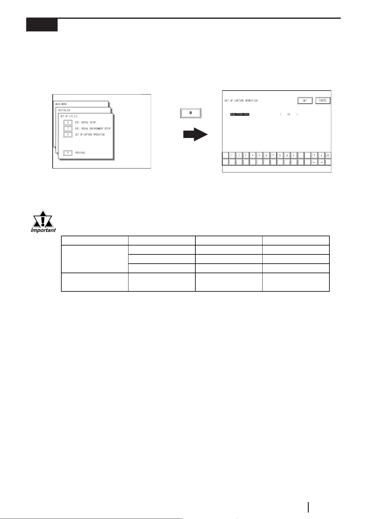
4.1.3 SET UP CAPTURE OPERATION
p
This setting screen allows you to set the quality of a captured video image that will be
saved to the GP's CF card as a JPEG file.
To display the setting screen, select the "INITIALIZE", "SETUP I/O 1/2", "SETUP
I/O 2/2", and "SET UP CAPTURE OPERATION" screens. (This menu is displayed
only when the VM Unit is installed.)
QUALITY (1 - 100)
Enter the desired quality of the captured JPEG file. Reducing this setting's value will
reduce the size of the file, however, it will also reduce the image quality.
When saving a PAL input screen, only "Normal" size or full-screen capture is possible.
Capure Feature Display Size NTSC PAL
Video Screen
Caputure
Full-Screen
Ca
uture
Normal OK OK
1/14 mode OK NG
1/16 mode OK NG
-OKOK
GP2000 Series VM Unit User Manual
E4-5
Page 27
4.2 VGA/SVGA Display Adjustment
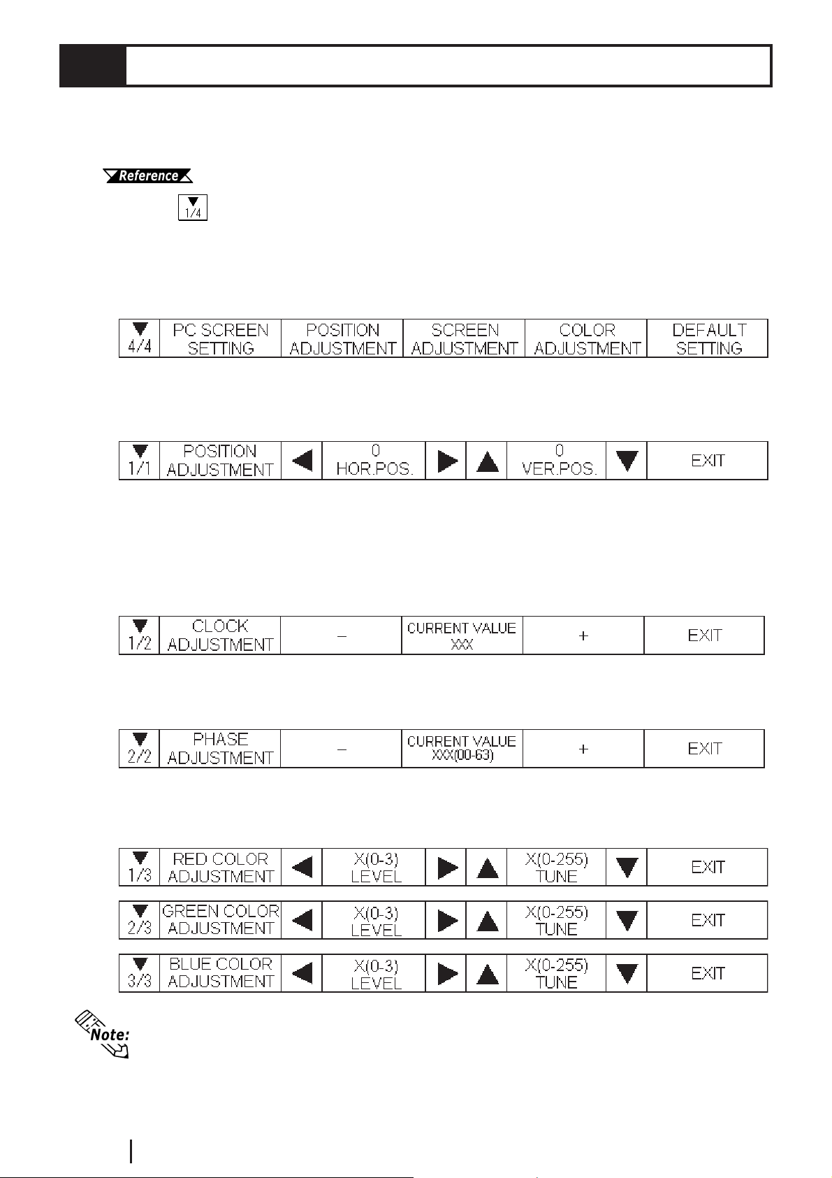
Use the GP2000 unit's "Menu Bar" to adjust this setting.
To display the Menu bar, refer to
"GP2000 Series User Manual" (sold separately).
Touching at the left side of the Menu bar three times calls up the "PC SCREEN
SETTING" screen.
Then, touch any of the detail settings shown below to call up that setting screen.
Touch "DEFAULT SETTING" to return all items to their initial settings.
POSITION ADJUSTMENT
Adjust the horizontal and vertical positions of the RGB IN image.
SCREEN ADJUSTMENT
Touch "CLOCK ADJUSTMENT" and/or "PHASE ADJUSTMENT".
"CLOCK ADJUSTMENT" is an option for adjusting the horizontal length of the
screen to align with the display width of the TFT panel.
The "PHASE ADJUSTMENT" is used to adjust the image when the image is not
properly displayed after the CLOCK ADJUSTMENT setting is used.
COLOR ADJUSTMENT
Use this setting to adjust the red, green and blue colors.
E4-6
The settings above are stored in GP unit's backup SRAM. At the same time, the
screen settings brought in via the RGB IN line will be saved based on the signal
type as a VGA, SVGA or VGAS70<640 x 400 dots> image file. When you change
the GP unit or the VM unit, these settings will need to be set (entered) again.
GP2000 Series VM Unit User Manual
Page 28
Chapter 5 : ERROR HANDLING
5.1 Troubleshooting
This section describes how to find the cause of a problem and solve it.
5.1.1 Possible GP or VM Unit Problems
If problems occur that are related to the VM Unit, sas there is no display on the GP,
refer to the table on the next page to find the cause of the problem. Once you identify
the problem, use the suggested countermeasures to correct it.
WARNING
To prevent an electric shock, be sure to check that no electricity is sup-
plied to the GP and VM units before performing any wiring.
The problems described in this chapter are tproblems caused only either the PC
or by the GP or the VM Unit. For the problems caused by a connected computer
or by an image I/O device, refer to that unit's manual.
GP2000 Series VM Unit User Manual
E5-1
Page 29
5.1.2 When Nothing Appears on the GP Screen
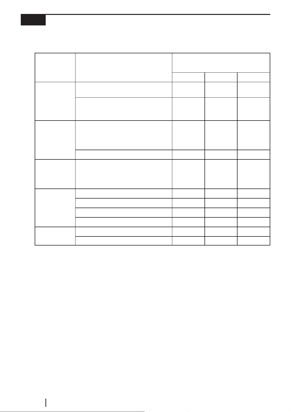
The following table shows the causes when the GP does not show images input from
the input device or when the GP's screen image is not displayed on the output device.
Tag Set tings
Video
Cont rol A rea
System Data
Area
Connection
Cause
V-tag (common mode) or v-tag (extended
mode) settings are incorrect.
v-tag (extended mode) indirect setting
designates a video screen number that
does not exist.
Video control area is incorrectly specified
when i t is s et v i a the touc h panel switc h or
PLC.
Invalid video ID number is specified.
System data area is incorrectly specified
when i t is s et v i a the touc h panel switc h or
PLC.
VM Unit is not properly connected.
Cable is not properly connected.
Cable is connected to improper channel.
Problem Area
VIDEO IN RGB IN RGB OUT
X
XX
X
XX
XX
XX
X
RGB IN and RGB OUT are reversed.
Unsupported device is connected.
I/O Device
I/O devic e s etting is incorrect.
X
When a VM Unit or GP malfunction is causing the problem, contact your local VM
Unit distributor.
E5-2
GP2000 Series VM Unit User Manual
Page 30
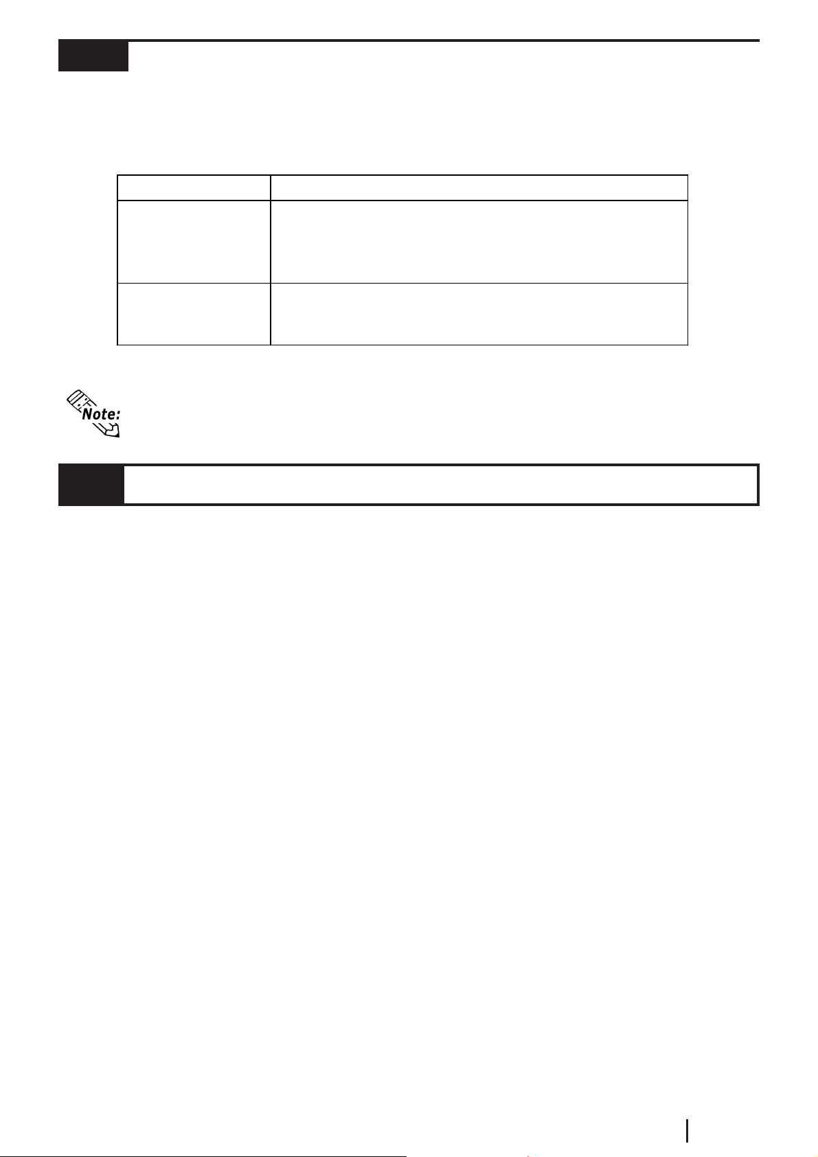
5.1.3 Video Input Signal Error Messages
When an error occurs due to input from external equipment (i.e. a signal output from
that equipment), the video screen will not be refreshed and one of the following error
messages will appear.
Error Message Cause
The video cable may be in cor rect l y connected, cu t , or a
Video Input Signal
Error (CH*)
RG B Input Signal
Error
*1
*1 "CH*" indicates VM Unit channel numbers 0 to 3.
When multiple video or RGB input lines are used, if one of these lines' signals
causes an error, video screen refreshing of other input lines may stop.
con nected device may be damaged. To f ix t hese
problems, try sending the input signal again to that
channel.
The video cable may be in cor rect l y connected, cu t , or a
con nected device may be damaged. To f ix t hese
problem s, try sending t he inpu t sign al again .
5.2 Checking the VM Unit
Self-Diagnosis Feature
The GP features a self-diagnosis program that check if the system and interfaces are
all operating correctly.
Use the "DISPLAY PATTERN" feature to check the condition the VM Unit's
VIDEO IN I/F.
Be sure to check the interface while the VM Unit is installed in the GP.
While in the GP unit's OFFLINE mode, touch "MAIN MENU", "SELF-DIAGNO-
SIS", and "DISPLAY PATTERN" to enter this area.
Look at each of the screen patterns (Total: 8 screens) and at the "DISPLAY ON/OFF
CHECK".
Check that the display patterns are displayed properly.
GP2000 Series VM Unit User Manual
E5-3
Page 31

Memo
E5-4
GP2000 Series VM Unit User Manual
 Loading...