

Page 1
Evacuation system
EN60849 CEI100-55
SYSTEM MANUAL
Page 2

Page 3

3
INDEX
PRELIMINARY Pag. 4
PROEVAC SYSTEM STRUCTURE Pag. 5
PRINCIPAL SYSTEM FUNCTIONS
− Line Diagnostic
Pag. 6
− Back up Amplifier
Pag. 6
− Feedback loop
Pag. 7
EV UNCE
− Generalities
Pag. 8
− Power supply
Pag. 8
− Input/output signal connections
Pag. 9
− Remote control
Pag. 10
− Technical Characteristics
Pag. 10
− Functions and control
Pag. 11
EV COMX
− Generalities
Pag. 12
− Power Supply
Pag. 12
− Input/output signal connections
Pag. 12
− Option
Pag. 13
− Technical characteristics
Pag. 13
− Functions and control
Pag. 14
EV SCDIA
− Generalities
Pag. 15
− Input/output signal connections e
Pag. 15
− Options
Pag. 15
− Technical Characteristics
Pag. 16
− Functions and Control
Pag. 16
EV BMH
− Generalities
Pag. 17
− Power Supply
Pag. 17
− Input/output signal connections
Pag. 17
− Technical Characteristics
Pag. 18
− Functions and Control
Pag. 18
EV MFIRE
− Generalities
Pag. 19
− Power supply
Pag. 19
− Input/output signal connections
Pag. 19
− Technical Characteristics
Pag. 20
− Functions and control
Pag. 20
OPERATING MODE
− System conncections
Pag. 21
− System switching
Pag. 21
− Configuration
Pag. 22
− System start up
Pag. 23
− Microphone stand
Pag. 24
− Remote inputs
Pag. 25
− Fault indication
Pag. 26
− Factory setting
Pag. 26
− General Reset
Pag. 26
− Microphone consoles wiring
Pag. 27
Page 4

4
PRELIMINARY
The European Standards EN 60849 title or “SOUND SYSTEMS TO SAFETY PURPOSES”
indicate clearly the technical principle to apply to in the systems and apparatus involved in a
correct and safety habitats and zones evacuation in case of emergencies status
There are some standards law regulations for sound alarm system . Such sound alarm systems
apply to the alarm messages diffusion is some buildings categories through loudspeakers.
Such systems are obligatory in the following cases:
In schools buildings : schools category 3-4-5- M. L 26/08/1992 (G.U. 16/09/1992 n° 218).
In hospitals, clinics ( M.L 18/09/2002 (G.U. 27/09/2002 n° 27).
The law 626 of 19/09/1994 and M. L 10/03/1998, Official edition G.U. n° 81 of 07/04/1998,
suggest to adopt such sound system for safety evacuation throughout loudspeaker alarm
message diffusion in public habitat accordingly to emergencies risk levels
To apply to such standards, the PA systems for sound/paging and music diffusion must have the
following features :
− Mixer amplifiers control .
− Loudspeakers line efficiency distribution in the various zones involved by the main system.
− Manual and automatic alarm message diffusion.
− Emergency microphone stand (VV.FF.) control.
− Spare amplifier activation in case of amplifier default
− Alarm message intelligibility independently to background noise level.
− Chime tone signal of a duration of 4 to 10 seconds prior alarm message diffusion
− Message pre- recorded and stored in a non volatile memory to ensure the message availability
when necessary.
− The announcement system activation within 3 seconds of the emergency status
− The installation must be subdivided in various zones and can foresee different messages per
different zones
The loudspeakers involved in the system must be fire resistant for at least 30 minutes ( metallic
structure , anti flame cover , ceramic terminal screws etc..).
Availability of an emergency power supply unit ( UPS).
Page 5

5
PRO EVAC STRUCTURE
EV UNCE Main central unit for system control
EV COMX Modular unit for commutation and zones module housing
EV SCDIA Diagnostic module for amplifiers chain
EV RRA Unit for level noise measurement and for automatic volume control
EV BMH Standard microphone stand for general call and for zones call
EV MFIRE Emergency microphone stand ( fireman call station)
AUP120R
AUP240R
AUP480R
A
UP4150/4250
Power units for diffusion at constant voltage 100V
CS6TALEN
PR10TALEN
TR15TALEN
UPSPRO1000
UPSPRO2000
UPSPRO3000
Loudspeaker at 100 V constant voltage
UPS Unit
Page 6

6
SYSTEM FUNCTION PRINCIPALS
LINE DIAGNOSTIC
PRO EVAC system is a modular system, for each line there is a zone card to be inserted in the
commutation unit
Diagnostic system inserts in the amplifying chain at regular interval of 1” an unheard pilot tone of
22 KHz. At the amplifier output and at end line loudspeaker, the tone pilot survey is done in a
constant way. In case of this pilot tone absence, the system acts as follows:
1) Tone pilot absence from the amplifier output ( amplifier default) .
− The default indicator on the commutation unit display is switched on
− Main unit default sound signal activation( buzzer).
− Main unit and microphone stands display amplifier default.
− The event is memorised in event log memory and in eventual print purposes when
available.
− Loudspeakers line commutation to back up amplifier – if back up amplifier available-
2) Tone pilot absence at end loudspeakers line (Line default).
− The default indicator of the commutation unit front panel is switched on.
− Main unit default sound signal activation (buzzer).
− Main unit and microphone stands display line default .
− The event is memorized in event log memory and in eventual (when available) print
purposes .
BACK UP AMPLIFIER
PRO EVAC system is designed to connect one or two back up amplifiers to each commutation unit
When only one spare amplifier is connected (SPLIT OFF) all zones modules inserted in the
commutation unit – in case of default- commute audio input and loudspeakers line to the same
amplifier. Statistically it is improbable that two amplifiers are in default contemporaneously. But to
remedy it is necessary to define the back up amplifier to ensure the zones/line necessary power
connect 100V output to terminal BCK 1 OUT and bridge BCK 1 OUT with BCK 2 OUT.
To ensure a good power repartition – in case of amplifier default- it is possible to connect 2 back
up amplifiers (SPLIT ON). In this case the commutation unit is subdivided in 2 groups s of modules
In case of zone 1 to.. 4 amplifier default the loudspeakers lines will be commuted to the first spare
amplifier . In case of zone 5 to ..8 amplifier default , the loudspeakers line will be connected to the
second spare amplifier.
It is necessary to foresee at least one back up amplifier for each commutation unit installed.
It is necessary to reset the system – accordingly to EN 60849 rules- and because the default signal
persists- even if the operating continuity is ensured because the loudspeakers line are connected
to back up amplifier .
The zones modules survey the amplifier default and commute to the back up amplifier, but are not
considered by programming purposes. Zones modules are involved only by general or non
selective call.
Page 7

7
LOOP FEEDBACK
The feedback loop line is necessary to check the loudspeakers line continuity. To ensure an
effectual control, the loudspeakers installation must be configured to have one sole line and is
connected to all loudspeakers without derivation ( daisy chain connection) . To the first diagnostic
module must be connected the first loudspeaker and to the second loudspeakers so on …to the
last loudspeaker. To this last loudspeaker must be connected the couple of loop wire .
In this way it is possible to check eventual interruptions due line short circuit as stated in point “j”
paragraph 5.3 of EN 60849 standards.
The line circuit default survey is effected by the diagnostic system but there is no commutation in
case of line interruption (short circuit) . The loudspeakers connected to the line section
continuously connected to the zone module are powered normally ( for example line interruption at
a certain point).
Obviously the system can not check the single loudspeaker status ( not required by EN 60849
standards) at the exception to a great line impedance decrease due to the consequent signal
attenuation and then tone pilot absence.
Page 8

8
EV UNCE
EV UNCE
GENERALITIES
The main central unit features different system components configuration control and
setting/operating data entry purposes. This unit communicates with microphone stands and
provide to the audio signal conversion The central unit is as follows equipped:
− LCD display for data illustration.
− Keys for standard system setting.
− Chip key card for system data modification.
− Led indicator for immediate and main functions visualisation status.
− Double Bus input for standard microphone line.
− Input with priority for emergency call station (VV.FF.).
− 2 audio inputs (Tuner, CD, Tape, etc.).
− One audio input for advertisements message sources .
− One audio input for central telephone call.
− One slot for pre-recorded messages card insertion.
− 4 programmable audio outputs for music and messages diffusion.
− One RS232 serial for PC connection purposes.
− 6 inputs for remote contact of alarm fire central or similar units.
POWER SUPPLY
The apparatus is designed to be power supplied 230Vac - 50÷60Hz.
If you switch on and there is no signal, check the fuse and replace it eventually with a fuse with the
same characteristics .
Unplug before connecting to the main power supply, open the apparatus cover to replace fuse.
Page 9

9
INPUTS/OUTPUTS SIGNAL CONNECTIONS
- AUDIO BUS
The plug RJ45 8/8 is used for AUDIO BUS connection between the central unit and commutation
unit (To plug AUDIO IN). this Bus vehicles 4 audio signals : Music 1-Music 2- Messages- calls.
- DATA BUS
Plug RJ45 8/8 is used for Bus data connection between the main central unit and the
commutation unit (Plug DATA IN). this Data Bus vehicles the information necessary for
Diagnostic control purposes and the information involving the configurations sent to zones modules
- MIC BUS
Two plugs RJ12 6/6 are used for microphones chain for a maximum of 32 stands ( including the
emergency one VV.FF.). The two plugs are linked and allow to effect the microphone chain
ramification. Cascade connection through UTP CAT5. Each stand has a double plug for line and
next stand receipt.
- EMG
Plug RJ45 8/8 is used for priority line dedicated to emergency stand VV.FF. Throughout this
controlled line, the stand can send emergency general call, Such stand signal has an absolute
priority on digital system signals on audio and on any other audio source in function . The
connections are through UTP CAT5.
- AUX 1
Plug RCA stereo mixed is used for audio source for music diffusion . Throughout a PC it is
possible to set in which zone connect to this input the signal audio must be sent.
- AUX 2
Plug RCA stereo mixed is used for audio source connection for music diffusion. Throughout a PC
it is possible to set to which zones the audio signal must be sent.
- MSG
Plug RCA stereo mixed is used to connect audio source for general communication or
advertisement message diffusion. Such audio channel is activated throughout a PC key and allows
to send the source audio signal : general communication or to one zone or to one area from the
same key till the channel close status is not sent to the central . Such input has the priority on
AUX1 and AUX2 inputs.
- TEL
Plug RCA mono unbalanced is used for audio signal connection for voice call- general
communication or throughout a telephone central, the signal to apply must be a “pure” audio signal
LF . It is not possible to connect directly a telephone list from an internal telephone central .
The signal breadth activated a VOX PAGING circuit and allow to diffuse the announcement in all
zones with priority on all music sources.
Page 10

10
REMOTE CONTROL
- RS232
Plug RS232 serial Sub-D 9 pins is used to connect the central unit to a PC. Thanks to the specific
software PROEVAC it is possible to set the data even per single zone and in a different way.
Alternatively it is possible to connect a serial print machine for the continuous alarm message print.
- REMOTE INPUTS
Terminal screw EUROBLOCK to be extracted 6 inputs are used for connections between the
main central unit and the apparatus with external keys. The inputs can be PC programmable for
different functions execution ( alarm general message start up, zone selection, area selection,
alarm message cancellation).
The balanced inputs not used must be maintained closed through a
THECHNICAL CHARACTERISTICS
Bd9+ YTILIBISNES TUPNI XUA
mhoK02 ECNADEPMI TUPNI XUA
Bd0 TUPNI YTILIBISNES 2GSM
mhoK02 TUPNI ECNADEPMI 2GSMI
Bd0 YTILIBISNES TUPNI LET
mhoK02 ECNADEPMI TUPNI LET
mhoK2,2 decnalab 4 STUPNI ETOMER
2 unbalanced N.C.
232SR CP LORTNOC ETOMER
23 ).FF.VV GNIDULCNI( SDNATS FO XAM .ON
zH06÷05 caV032 : YLPPUS REWOP
Consumption 15VA
mm042 x 88 x 344 )D x H x L( noisnemiD
WIEGHT 3,8Kg
resistance of 2,2Kohm whilst the unbalanced inputs (5 and 6) must be closed by a jumper( Bridge).
Page 11
11
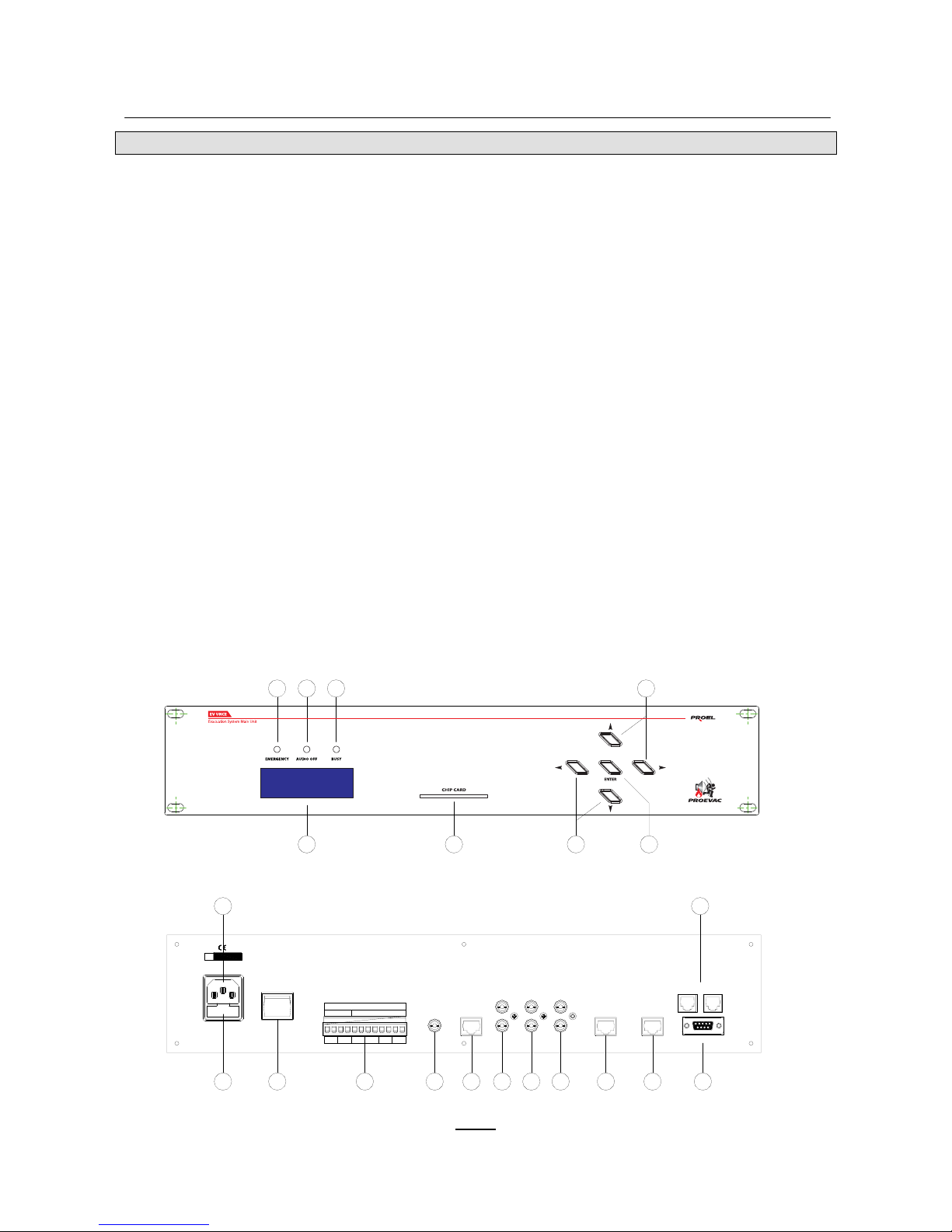
KEYS AND FUNCTIONS (Fig. 1)
1) POWER – SWITCH ON .
2) DISPLAY –LCD rear illuminated 20x4, to visualise the system functions
3) ENT – key enter the various menu steps and to confirm the setting input.
4) ARROW – manager keys for functions executions and setting data .
5) CHIP CARD – chip card reader and key for access and data modification (AVAILABLE IN FUTURE SYSTEM
UPGRADE)
6) EMG – led for active status indication for emergency call
7) MUSIC OFF – led indicator for music of general status
8) BUSY – led indicator for current call
9) MAINS – main power supply plug 230Vac.
10) FUSE – AC protection fuse 250mAT (delay).
11) REMOTE INPUTS – inputs for alarm central or similar purposes connection.
12) TEL – audio input for telephone central
13) AUDIO BUS –audio Bus output for unit commutation.
14) AUX 1 – audio input for audio source .
15) AUX 2 – audio input for audio source .
16) MSG – audio input controlled for advertisement or similar messages .
17) EMG –input with priority for emergency microphone stand .
18) DATA BUS – in/out BUS data between central unit and commutation unit
19) RS232 – serial for PC or print machine connection.
20) MIC BUS – digital input for microphone stand chain
Fig. 1
S.N.
230Vac 50÷60Hz
MAINS
FUSE T250mA
BALANCED 2,2K
N.C.
REMOTE INPUTS
6 543
2 1
TEL AUDIO BUS
AUX 1 AUX 2
MSG 2
EMG DATA BUS
MIC BUS
RS232
FUSE
1918
17
1615
14
13
1211
10
209
6 7 8 4
5
4
3
2
POWER
ON
OFF
1
Page 12

12
EV COMX
GENERALITIES
Commutation unit -controlled by the central unit - is designed to house the diagnostic zones
modules and 8 audio zones signal selection: each unit can select 8 audio zones signal . It is
possible to connect up to 10 commutation units in cascade and realize a system of 80 zones. The
data exchange and communication are done through 2 Bus( Audio and Data).and thanks to the
appropriate software. The commutation unit composition is as follows:
− 8 slot for diagnostic module insertion.
− Led for immediate visualisation of the zone module status.
− Connection module with the central and the next units.
− Connection module for back up amplifiers (1 o 2).
− Power supply 230Vac.
POWER SUPPLY
This apparatus main power supply 230Vac - 50÷60Hz.
In case when switched, there is no signal , check protection fuse and replace eventually with a fuse
with the same characteristics .
Unplug before connecting the apparatus to the main power supply 230Vac, remove metallic cover
before fuse replacement.
Page 13
13
OUTPUT/INPUTS SIGNAL CONNECTIONS
- AUDIO IN
PLUG RJ45 8/8 for Bus audio connection between commutation unit and the main central (to
AUDIO BUS PLUG). The Bus vehicles 4 signals : Music1 Music2, Messages and calls.
- AUDIO LINK
Plug RJ45 8/8 for Audio Bus connection between the commutation unit and the central unit in
cascade ( to plug AUDIO IN to next unit ).
- BUS IN
Plug RJ45 8/8 for data Bus connection between the commutation unit and central unit (plug
DATA BUS). The bus vehicles information involving system diagnostic control and zones modules
configuration.
- BUS LINK
Plug RJ45 8/8 for Bus data connection between the commutation units in cascade ( to BUS IN
plug of next unit)
- BCK 1 IN
Terminal screws Euroblock to extract 3 ways for balanced audio Low frequency signal connection
between commutation unit and back up amplifier
- BCK 2 IN
Terminal Euroblock to extract 3 ways for Low frequency balanced signal connection between
commutation unit and next back up amplifier.
- BCK 1 OUT
Terminal Euroblock to extract 2 ways for 100V audio feedback signal between the first back up
and the commutation unit.
- BCK 2 OUT
Terminal Euroblock to extract 2 ways for 100v audio feedback signal between the second back up
amplifier and the commutation unit.
OPTIONS
- SPLIT
2 positions switch for back up operating mode selection. It is possible to set the system to have
only one back up amplifier for 8 zones or 2 back up amplifiers one per 4 zones .
TECHNICAL CHARACTERISTICS
SLOT No. 8
No. max of units in cascade 10
Connections 2 x UTP CAT5 50cm
Power supply: 230Vac 50÷60Hz
Consumption (with 8 modules) 50VA
Dimensions (L x H x D) 443 x 132 x 215mm
WEIGHT (WITH 8 MODULES) 8Kg
Page 14
14
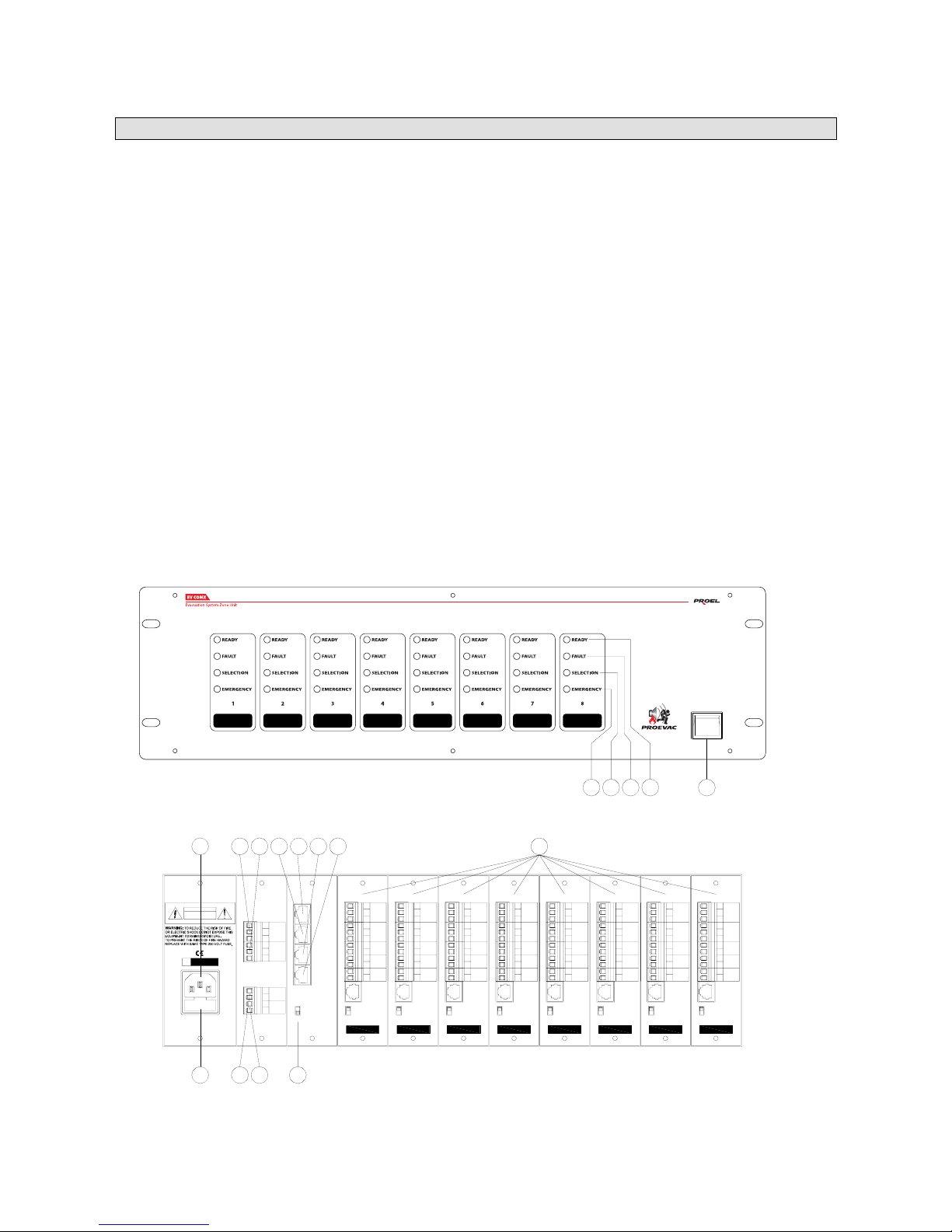
KEYS AND FUNCTIONS (Fig. 2)
1) POWER – to power on the unit.
2) RDY – zone module Led indicator.
3) FAULT – audio and card default led indicator.
4) SEL – communication status with main central unit led indicator.
5) EMG – emergency call active led indicator.
6) MAINS – plug for 230 Vac main power supply .
7) FUSE – AC protection fuse 250mAT (delayed).
8) BCK 1 IN – audio Low frequency output to be connected to back up n°1 amplifier input.
9) BCK 2 IN –audio low frequency output to be connected to back up n°2 amplifier input.
10) BCK 1 OUT – 100V audio input to connect to back up n°1 amplifier input.
11) BCK 2 OUT – 100V audio input to connect to backup n°2 amplifier input
12) SPLIT – Switch to select the no. of back up amplifiers.
13) DATA IN – Data Bus input in receipt of main unit DATA Bus .
14) DATA LINK – data Bus output towards DATA IN commutation unit and the next commutation input
15) AUDIO IN – audio Bus input in receipt from main unit AUDIO BUS .
16) AUDIO LINK – audio Bus output towards AUDIO IN commutation unit and next commutation unit input.
17) EV SCDIA – diagnostics zone module.
Fig. 2
ON
BCK
OFF
RELAY
AMP
IN
C
NC
NO
GND
+
-
+
-
+
-
+
-
LOOP
SPKR
AMP
OUT
REMOTE
CONTROL
ON
BCK
OFF
RELAY
AMP
IN
C
NC
NO
GND
+
-
+
-
+
-
+
-
LOOP
SPKR
AMP
OUT
REMOTE
CONTROL
ON
BCK
OFF
RELAY
AMP
IN
C
NC
NO
GND
+
-
+
-
+
-
+
-
LOOP
SPKR
AMP
OUT
REMOTE
CONTROL
ON
BCK
OFF
RELAY
AMP
IN
C
NC
NO
GND
+
-
+
-
+
-
+
-
LOOP
SPKR
AMP
OUT
REMOTE
CONTROL
ON
BCK
OFF
RELAY
AMP
IN
C
NC
NO
GND
+
-
+
-
+
-
+
-
LOOP
SPKR
AMP
OUT
REMOTE
CONTROL
ON
BCK
OFF
RELAY
AMP
IN
C
NC
NO
GND
+
-
+
-
+
-
+
-
LOOP
SPKR
AMP
OUT
REMOTE
CONTROL
ON
BCK
OFF
RELAY
AMP
IN
C
NC
NO
GND
+
-
+
-
+
-
+
-
LOOP
SPKR
AMP
OUT
REMOTE
CONTROL
ON
BCK
OFF
RELAY
AMP
IN
C
NC
NO
GND
+
-
+
-
+
-
+
-
LOOP
SPKR
AMP
OUT
REMOTE
CONTROL
OFF
SPLIT
ON
DATA LINK
DATA IN
AUDIO IN
AUDIO LINK
BCK 1
IN
GND
+
-
BCK 2
IN
GND
+
-
+
-
BCK 2
OUT
+
-
BCK 1
OUT
S.N.
230Vac 50÷60Hz
MAINS
FUSE T250mA
FUSE
CAUTION
RISK OF ELETTRIC SHOCK
DO NOT OPEN
7
6
10
8 139
111412
15 16
17
POWER
ON
OFF
1
2
3
4
5
Page 15

15
EV SCDIA
GENERALITIES
Zone diagnostic module, complying with EN 60849, features a specific electronic diagnostic
system to ensure an autonomous control of the amplifying chain and eventual commutation to
back up amplifier . This control is done for each amplifier and for each loudspeakers line; eventual
anomalies are transmitted to the main central unit to provide for default indication .
The module is as follows equipped:
− Switch system for zone configuration .
− Output/input connections for low frequency and 100V signal towards the zone amplifier.
− Output/input connections for 100 V loudspeakers line and feedback loop.
− NA and NC remote contact output connections.
− Automatic remote volume connection module.
− Switch to allow back up operating mode.
OUTPUT/INPUT SIGNAL CONNECTIONS
- AMP IN
Terminal EUROBLOCK to extract -3 ways to use for audio balanced Low frequency signal– to
connect between the zone module and the amplifier zone.
- AMP OUT
Terminal EUROBLOCK extract -3 ways to use for 100V feedback audio signal- to connect
between the zone amplifier and zone module.
- SPKR / LOOP
Terminal EUROBLOACK to extract -4 ways to use for 100V audio loudspeakers line. Loop cable
from the last loudspeaker line to connect to the appropriate terminal.
OPTIONS
- RELAY
Terminal EUROBLOCK to extract – 3 ways – to use for NA and NC contact connections towards
external apparatus to be controlled for particular call, general call o for emergency call and to
diffuse pre-recorded messages.
- REMOTE CONTROL
Plug 6/6 is used to vehicle data Bus between the zone module and its remote module to survey
the background noise and adjust automatically the volume.
- BCK
2 positions switch is used to allow each zone module to effect the commutation to back up
amplifier in case of default amplifier.
ON = Able OFF = Disable
Page 16
16
TECHNICAL CHARACTERISTICS
Low frequency signal at AMP IN output 0dB
Amplifier power to apply to AMP OUT input max 500W
Voltage to apply to Relay contact max 24Vdc 1A
Pilot tone frequency >20KHz
Internal connections Slot Bus 64 pin
Power supply 12Vdc
Absorption 300mA
Dimensions (L x H x D) 38 x 135 x 190mm
Weight 160g
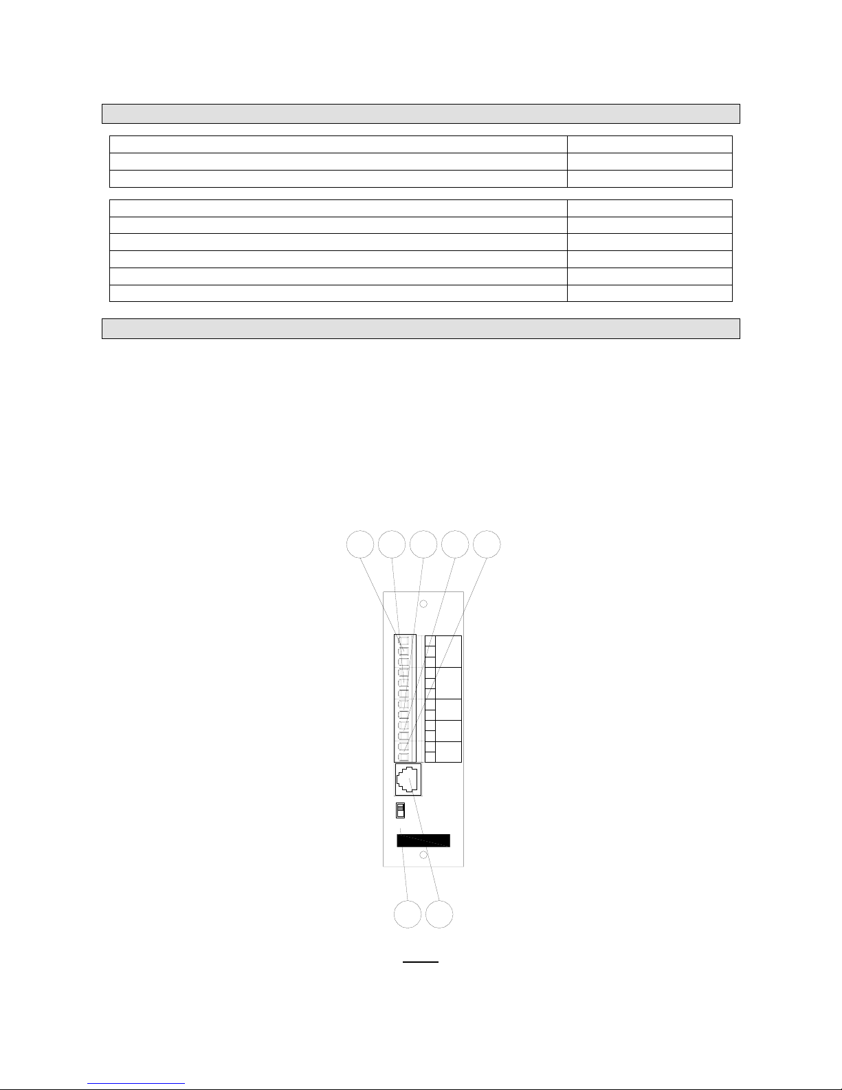
KEYS AND FUNCTIONS (Fig. 3)
1) RELAY – NC / NA Relay contact max 24Vdc 1A, for calls and messages activation .
2) AMP IN – Low frequency audio output to connect to amplifier zone.
3) LOOP –input for 100V audio loudspeakers feedback line .
4) SPKR – 100V audio loudspeakers line.
5) AMP OUT – 100V audio input to connect to zone amplifier output .
6) BCK –switch to back up operating mode activation.
7) REMOTE CONTROL – input for peripheral connection for background noise contro l.
Fig. 3
ON
BCK
OFF
RELAY
AMP
IN
C
NC
NO
GND
+
-
+
-
+
-
+
-
LOOP
SPKR
AMP
OUT
REMOTE
CONTROL
6
12
3
4
5
7
Page 17

17
EV BMH
GENERALITIES
This standard microphone stand is the user PC keyboard for messages diffusion, for selection call
per zone, per area or general call . The communication with main central unit is done throughout a
Digital Bus. Such bus vehicles audio, the information exchange between the microphone stand and
main central unit. This stand is desk use and features:
− Gooseneck electret microphone.
− Call selection Keyboard.
− LCD Display rear illuminated for current operation visualisation.
− Double plug Bus for digital line data receipt and next microphone stand data sending .
− Dip Switch internal for numerical stand configuration.
− Plug for external power supply.
POWER SUPPLY
Microphone stand can operate in DC or AC and is supplied with a power supply 230Vac/12Vdc .
Close to the stand ensure to foresee a main 230Vac plug.
INPUT/OUTPUT SIGNAL CONNECTIONS
- MIC BUS
Plug RJ12 6/6 are used for chain microphone stand connections. This chain can involve up to 32
stands (including emergency call station VV.FF.). The Two plugs linked allow to connect digital
line in receipt from the central unit or from previous stand to next stand . The connections are UTP
CAT5 ( 3 twisted wires).
Page 18
18
TECHNICAL CHARACTERISTICS
etertcelE - kcenesooG enohporciM
zH00051-001 esnopser ycneuqerF
Pick-Up-Pattern Cardioid
Sensibility -68dB
Impedante 100 ohm
caV21/cdV21 : egatlov rewoP
Absorption 100mA
Dimensions (L x H x D)
Microphone asta lunghezza
Weight
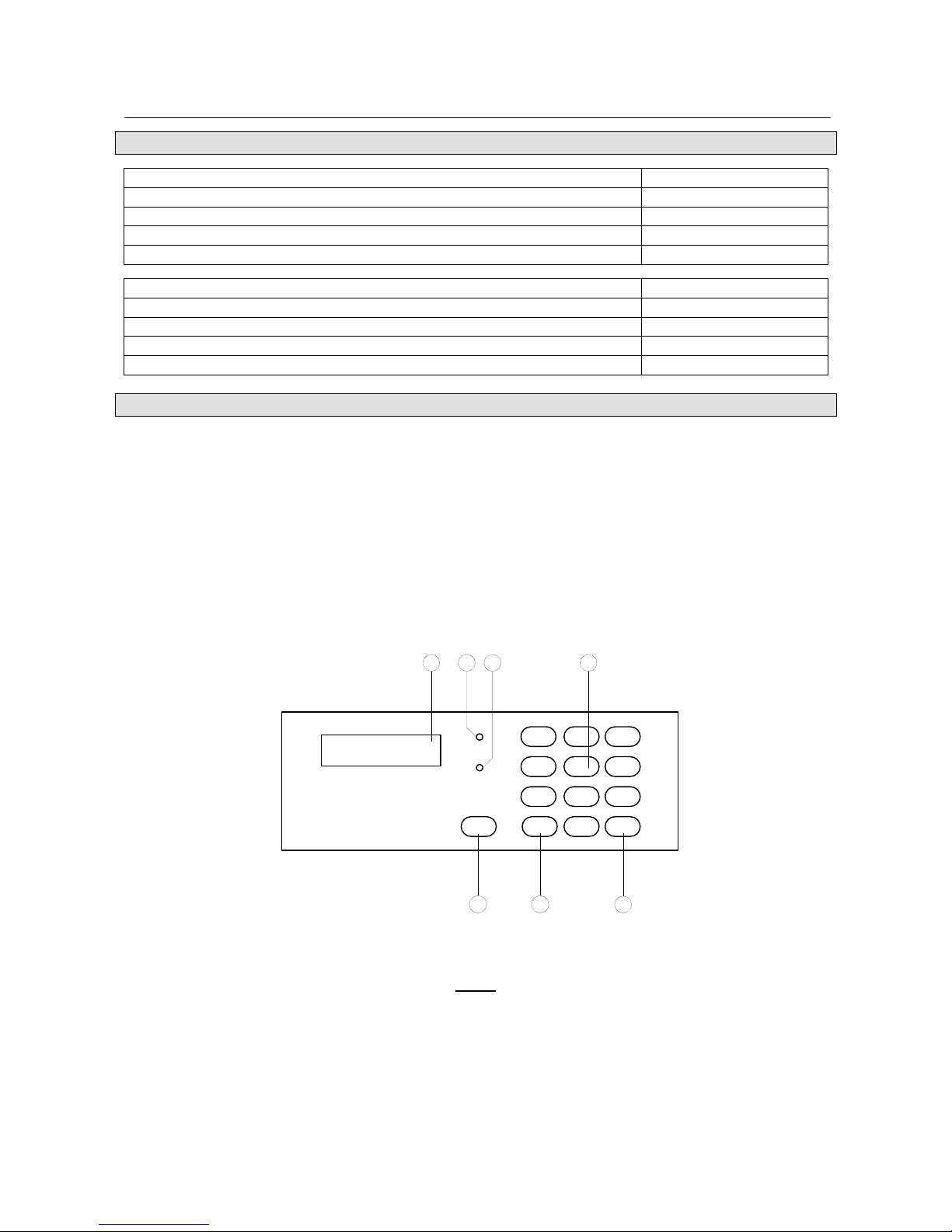
KEYS AND FUNCTIONS (Fig. 4)
1) DISPLAY – LCD rear illuminated 16x2, for basic functions visualisation.
2) PWR – Led power indicator.
3) BUSY – busy Bus led indicator .
4) 0÷9 – numerical keyboard for zone or area no. entry to call.
5) AREA – selection key for area call selection.
6) ZONE – selection call for zone selective call .
7) GENERAL CALL – General call selection key.
Fig. 4
Fig. 4
1 2 3
4 5 6
7 8 9
ZONE
CALL
GENERAL
0 AREA
5
42
3
1
67
PWR
BUSY
Page 19

19
EV MFIRE
GENERALITIES
Emergency microphone call or VV.FF., features the same standards microphone stand console,
in additional EV MFIRE is equipped by a microphone capsule with auto diagnostic system to
inform on eventual bad operating. EV MFIRE features a switch at two positions to commute from
normal operating mode (NORM) to Emergency operating mode (EMG),
Mode operating emergency allow to EV MFIRE send general call with absolute priority on all
system apparatus . Such function is available even when Digital system is absent . In fact with
such function EV MFIRE can send directly to the zone amplifier the signal. To ensure such
function, the microphone stand requires a specific connection to the main central unit, to
emergency Bus line.
This stand is designed for wall mounting purposes- mounting box.
Features:
− Omni directional dynamic microphone with push-to-talk activation push button.
− Keyboard for microphone call selection.
− LCD Display rear illuminated for current operation visualisation.
− Double Bus plug for digital line receipt and next microphone stand connection.
− Dip Switch internal for numerical stands configuration.
− Plug for external power supply source.
− Bus plug for emergency line.
− Switch for security block for operating mode selection .
PROEVAC SYSTEM CAN INVOLVE ONLY ONE V.V.FF EMERGENCY CONSOLE
POWER SUPPLY
The microphone stand is supplied with a power supply 230Vac/12Vdc. It is necessary to foresee a
plug close to the main 230Vac power supply.
In case of a black out, stands emergency operating mode (EMG) ensures a direct power supply
through Priority Bus connection to the main central unit. ( The main central unit then must be
connected to UPS ).
INPUT/OUTPUT SIGNAL CONNECTIONS
- MIC BUS
Two plugs RJ12 6/6 are used to allow chain microphone stands connections ( up to a maximum of
32 stands including emergency stand ). The two plugs linked allow to connect digital line in receipt
from the main central unit or from previous stand to next stand. The connections are UTP CAT5
cable.
- EMG
Plug RJ45 8/8 is used to connect emergency controlled line. Throughout such line alarm call can
be sent with priority on digital system purposes and on audio signal priority on all audio sources
involved by the configuration. The connections are done by UTP CAT5 cable.
- MIKE
Microphone plug 4 poles, is used for palm microphone connections. In normal operating
mode(NORM) to effect microphone announcement , it is not necessary to press PTT key but jut
press the corresponding key to the selected message. Contrarily for emergency operating mode.
To send the alarm call it is necessary to press PTT (Push-To-Talk).
Page 20
20
TECHNICAL CHARACTERISTICS
cimanyD - ramlaP enohporciM
zH0005-002 esnopser ycneuqerF
lanoitceridinmO nrettaP-pU-kciP
Sensibility -76dB
Impedance 500 ohm
caV21/cdV21 : egatlov rewoP
Absorption 100mA
Dimension (L x H x D)
Micophone cable length
Weight
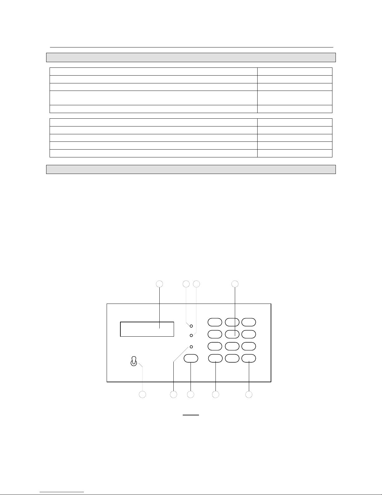
KEYS AND FUNCTIONS (Fig. 5)
1) DISPLAY – LCD rear illuminated 16x2, to visualise the basic functions
2) PWR – Power LED.
3) BUSY –Busy led indicator when the Bus is busy because for current calls from other sources.
4) 0÷9 – numerical keyboard compose zones or area corresponding no..
5) AREA – Selection key for area selection call .
6) ZONE – key for zone selection call.
7) GENERAL CALL – general call selection key.
8) MIC – Led for active microphone status indication (NORM).
9)
NORM / EMG – SWITCH FOR operating mode selection
.
Fig. 5
CALL
GENERAL
ZONE
0
1 2 3
4 5 6
7 8 9
AREA
5
42
3
1
6789
PWR
BUSY
MIC
EMG
HORM
Page 21

21
OPERATING MODE
SYSTEM WIRING
Before powering the system , effect the following connections:
− Connect the main unit to commutation unit throughout the appropriate Patch UTP CAT5
supplied with the system . Connect in cascade the eventual and additional commutation
units.
− Connect priority line to emergency microphone stand (VV.FF) and to the main central unit
throughout UTP CAT5 cable.
− Connect loudspeakers line and feedback loop to the respective zones module.
− Connect cascade microphone stands line to the main central unit throughout UTP CAT5
cable contained in the supply.
− Connect eventual audio sources to the main central unit.
Zones module must be numbered with the appropriate and included in the supply Dip-switch , pure
binary codification. Module installation must be effected in accordance with a consequential and
increasing way starting from 1.
SYSTEM SWITCHED ON
The PROEVAC different apparatus configuration switch on process must be effected accordingly
to a precise sequence.
1. Power all amplifiers including Backup ones.
2. Power commutation unit EV COMX.
3. power central unit EV UNCE.
TO switch off the system , effect contrarily the sequence:
1. switch off EV UNCE.
2. switch off the commutation unit EV COMX.
3. switch off the amplifiers.
The tone pilot control can be modified in case the amplifier volume is very low . Therefore ensure
that the amplifier volume are set not below half level volume.
When the commutation unit is powered check that the green LED RDY lights in correspondence to
zones modules inserted in the appropriate slot. Check also that the red LED (FAULT) are off. In
case one of these LED lights , it is necessary to check loudspeakers and feedback loop lines
connections. Adjust the amplifier volume to a higher level Once all control are effected , switch off
to switch on newly the commutation unit.
When the main central unit is switched on the system effects an initialisation procedure. On LCD
display appears the indication CHECK SISTEMA IN CORSO. After some seconds in case there is
no operating anomalies , the system is then in stand-by status, display visualise system status
sistema: OK. Contrarily in case of default or operating anomalies, The default individuated is
indicated in the display.
Page 22

22
CONFIGURATION
Some functions of PROEVAC system can be configured from the front panel of the main central
unit, other functions must be set by PC throughout an appropriate and supplied software
PROEVAC.
Programmable functions throughout front panel are :
− alarm reset.
− Zone Scan Module.
− Zone module for status illustration .
− Zone module for configuration illustration.
− Date and time setting.
− Audio setting (music on/off).
− Chime tone setting.
− VOX input setting.
− RS232 connections setting.
− Local monitor setting.
− Pre-recorded voice messages listening.
− Events log visualisation .
− General Reset of the central unit and default status setting.
Setting from the panel:
Press Enter (ENT) when the display visualise system status OK you can access to the
different functions. The functions are cyclic for each Enter key press. To modify value/data use
fleche keys display. modification has an effect on following press ENTER key.
Programmable functions throughout PC serial input are as follows:
− Alarm reset .
− Zone module scan .
− Zone module status illustration .
− Zone module configuration.
− Event log configuration.
− Zone module configuration setting.
− Remote input configuration setting.
− Full system memory setting.
− Recall and reset for back up setting .
− Event log administration and archives .
− Text message sent to microphone stands.
− Remote input activation simulation.
− MSG input administration and simulation
− Serial communication Text.
Page 23
23
SYSTEM START UP
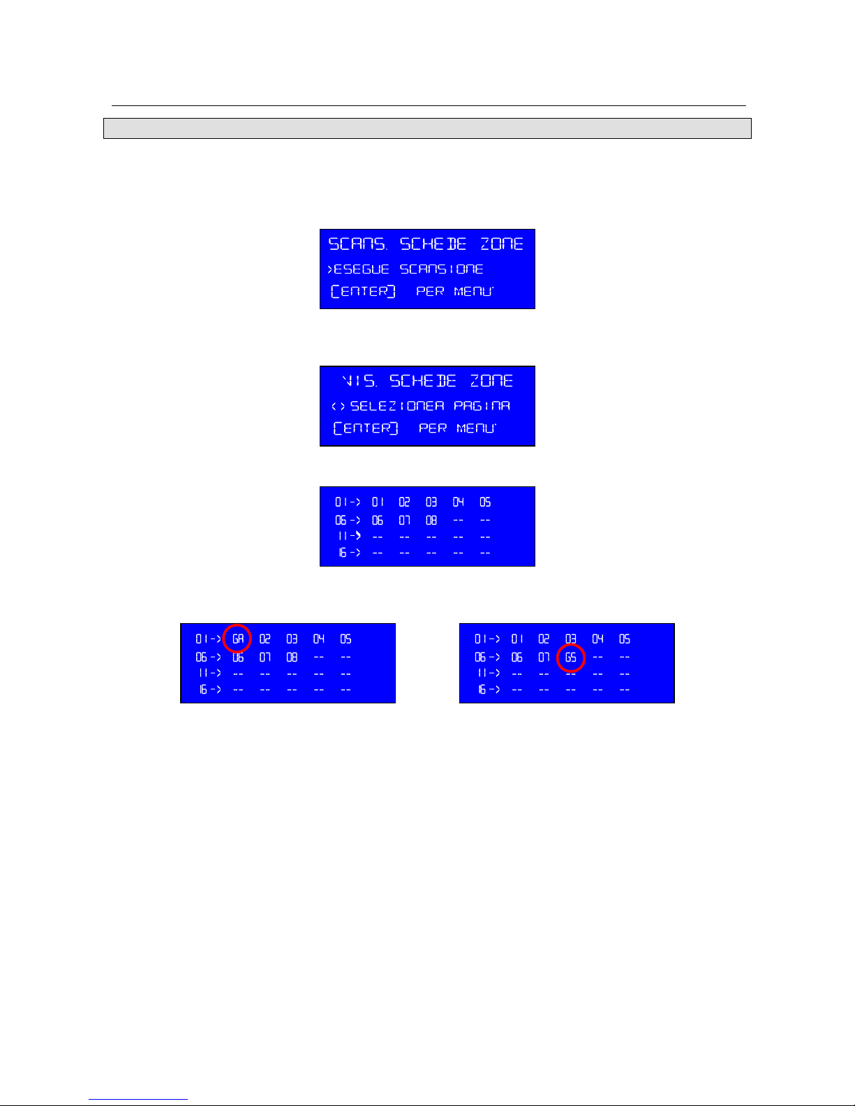
To effect the first system start up, It is necessary to scan the zones modules of the commutation
zone. From the front panel of the main unit, press Key ENTER to visualise the following menu:
SCANS. SCHEDE ZONA. Press shaft to start up scan operation.
Once the scan operation is effected , the following menu is displayed VIS. SCHEDE ZONA. The
next right shaft key pressing allows to visualise the status of the zones modules surveyed.
If the all the modules are perfectly working, the relevant identification codes will be indicated.
The modules in alarm audio defect status are GA indicated; the matrix in alarm for module
defect status are GS indicated.
Once the module scan is effected, the system memorize the setting data. In case the main central
unit is powered off, a manual scan is necessary.
Page 24

24
MICROPHONE STANDS
The periphery microphone stands are connected in cascade to the main central unit . Each stand
is equipped with an internal dip-switch-pure binary codification. The stands relevant numbers allow
the right main central unit identification when the stands the stands are activated for call
announcement purposes. These numerical codes are not necessarily consequential and in an
increasing way.
In the latest microphone stand in the chain ( set far from the central unit) end line bridge must be
inserted.
The emergency microphone stand (VV.FF.), requires 2 connections lines: one commune with the
other sands and an other direct connection to the main central ( EMG PLUG). The emergency
stand is also equipped with an internal dip-switch –pure binary codification to allow the main unit
central identification normal operating stand microphone mode. The emergency function is active
even when there is no local power supply. The emergency microphone stand operates only if
equipped with original PTT microphone. The eventual microphone capsule defect or the
microphone absence are displayed by the main unit central .
The connections cables with the main central unit must be pin to pin plug realized: for both lines:
standard line as well as for emergency line.
The microphone stand is keyboard equipped.: Keys are numbered from 0 to 9 plus 3 keys for calls
− For general call press and keep pressed General call key . The ring lights up and display
visualises CONNECT indicating the microphone activation. If the line is busy with another
call, the display visualises BUSY. The Led BUSY lights up If the line is busy with other
microphones calls.
− To send a selected call to a selected zone, it is necessary to dial the selected zone number
(from 1 to 80) and then press and keep pressed the zone key. In case of no present zone
selection an error message is displayed.
− To send a message to a selected area , enter the selected area number (from 1 to 40) and
then press and keep pressed the Area key . In case of non present area selected, an error
message is displayed.
The emergency microphone stand at normal conditions ( switch to NORM position), has the same
functions of the periphery microphone stands . To effect a call it is not necessary to press PTT key
of palmar microphone.
For emergency call, position Switch on EMG . Press PTT key, a general call with absolute priority
on digital electronic system. On the main central unit display appears: CHIAMATA DI
EMERGENZA, the EMG led of commutation unit panel lights up . The emergency functions are
active even when there is no local power microphone supply.
Page 25

25
REMOTE INPUTS
The main unit is 6 programmable remote inputs equipped . Available on EUROBLOCK Terminal.
The first 4 inputs are balanced and must be closed on a resistance of 2.2 K-ohm to avoid to
generate alarm signal: Serial or Parallel to the activation contact. ( Serial if the contact is normally
closed or in parallel if the contact is normally open.
The other 2 inputs do not generate alarm signal if kept normally closed.
The remote inputs can be programmed by the appropriate software. It is possible to set for each
input the following alarm function:
− To activate a recorded voice message , to diffuse it in a considered zone or in an area or
all zones.
− To activate a recorded voice message, to diffuse it in a considered zone, in a considered
area or in all zones and to display on the microphone stands a text message.
− To display a text message on microphone stands.
− alarm reset .
The balanced inputs not used must be maintained closed through a resistance of 2,2Kohm whilst
the unbalanced inputs (5 and 6) must be closed by a jumper( Bridge) .
If not differently required, the first Three balanced inputs are programmed in default to reproduce
3 different messages: Fire alarm in general diffusion:
Input Description
1 Message test for an eventual fire alarm.
2 Message for a real fire alarm and the immediate evacuation request
3 Message for alarm end and possible return the area
The messages pre-recorded are diffused in English and Italian .
Page 26

26
DEFAULT INDICATION
The amplifier operating and loudspeakers line control ( interruption or short circuit) is done thanks
to pilot tone presence in the amplifying chain . This pilot tone feedback is checked throughout Loop
the loudspeakers lines or Loop error cabling ( example loop line is connected to the wrong zone
module or a law amplifier volume creates the default detection through RED LED FAULT indicator
Such LED is set on commutation unit front panel with reference to the corresponding zone module.
The missing or non correct emergency microphone connection or a wrong emergency call
activation can create the default indication on central unit display . The system can survey the
PALMAR microphone PTT absence for the emergency microphone stand.
Along with the diffusers line, amplifiers and emergency microphone stand control the system is
designed to ensure further diagnostic and default indication.
− Specific default for zone module.
− Internal voice message card default.
− Microphone stands communications decoder default
− Audio Bus between central unit and commutation unit default.
FACTORY SETTING
Each PROEVAC system is set from the factory as follows:
Data Value
Time and date 00:00:00 01-01-2000
Music NO (off)
DING DONG chime tone NO (off)
Local Monitor MUTE
RS232 serial NO (off)
Alarm 1 input Message 1 – General call
Alarm 2 input Message 2 – General call
Alarm 3 input Message 3 – General call
Alarm 4 input No message
Alarm 5 input No message
Alarm 6 input Alarm stop
Zone music Volume 99
Music source per zone AUX 1
GENERAL RESET
To apply to the system factory setting and to cancel events log please contact Proel Installation
service dept.
Page 27
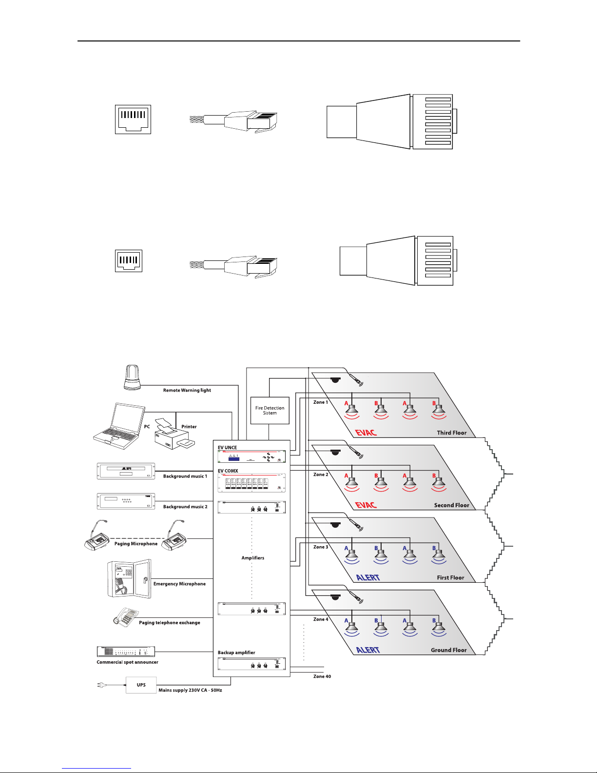
UTP CAT5 cable and RJ45 connector for EV MFIRE microphone stand connections are
accordingly to standards EIA/TIA-568B
UTP CAT5 cable and RJ12 connector for EV MFIRE emergency microphone stand and EV BMH
zones call details:
APPLICATION USE EXAMPLES.
27
1
8
orange/white
orange
green/white
blue
blue/white
green
brown/white
brown
1
2
3
4
5
6
7
8
1 8
1
6
orange
black
red
green
blue
yellow
1
2
3
4
5
6
1 6
FEMALE PLUG MALE PLUG
FEMALE PLUG MALE PLUG
Page 28

28
NOTE
Page 29

PROEL S.p.A.
(Milan Offi ces)
via Walter Tobagi, 30
Località Canzo - 20068
Peschiera Borromeo (Mi)
 Loading...