

Page 1
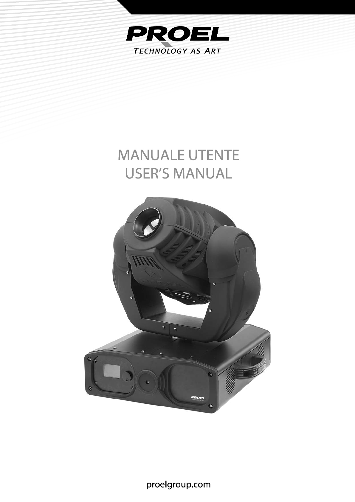
BLACKMOON 575 SPOT
PLML575SCNXP
2
Page 2
INDICE
NORME DI SICUREZZA...................................................................................................3
ALIMENTAZIONE .............................................................................................................4
MONTAGGIO IN SOSPENSIONE.................................................................................. 4
CONNESSIONE CON UNA LINEA DMX.....................................................................5
MESSA IN FUNZIONE...................................................................................................... 6
IMPOSTAZIONI DEL MENU........................................................................................... 6
MANUTENZIONE............................................................................................................10
DATI TECNICI...................................................................................................................10
TABLE OF CONTENTS
MAIN GUIDELINES.........................................................................................................11
AC POWER........................................................................................................................12
OVEREAD MOUNTING .................................................................................................12
DMX 512 CONNECTION ..............................................................................................13
OPERATION......................................................................................................................14
MENU SETTINGS ............................................................................................................14
BASIC SERVICE ................................................................................................................18
TECHNICAL DATA..........................................................................................................18
2
Rev.01- 05/09
Page 3

NORME DI SICUREZZA
- Attenzione! Questo prodotto non è adatto ad un uso domestico.
- Leggere il presente manuale prima di dare corrente all’apparecchiatura e di installarla, seguire le
precauzioni di sicurezza elencate sotto ed osservare tutti gli avvertimenti indicati nel presente
manuale e stampati sull’apparecchiatura. Si prega di contattare un distributore PROEL per ricevere
assistenza per qualsiasi dubbio su come attivare l’apparecchiatura in modo sicuro. Rivolgersi ad un
tecnico qualificato per qualsiasi operazione di manutenzione non descritta nel presente manuale.
- Non modificare l’apparecchiatura e non installare accessori e kit di aggiornamento che non siano
quelli originali PROEL.
- Rivolgersi a personale qualificato per la manutenzione.
- Temperatura ambiente massima Ta = 35°C.
- Consultare l’etichetta per il tipo di lampada di ricambio.
- Adatto per il montaggio su superfici con caratteristiche ignifughe normali.
- Non guardare direttamente in direzione della luce.
- Rischio di fuoco, scosse elettriche e bruciature.
- Uso esterno.
- Non ostruire le ventole di scarico.
- Schermi, lenti o schermi ultravioletti devono essere sostituiti se appaiono visibilmente danneggiati al
punto che la loro efficacia sia compromessa, per esempio da incrinature o profonde graffiature.
- La lampada deve essere cambiata se danneggiata o deformata termicamente.
- Se il cavo di alimentazione esterno di questa apparecchiatura da illuminazione è danneggiato, deve
essere sostituito con un cavo speciale, disponibile esclusivamente presso i rivenditori PROEL.
- Attenzione: scollegare sempre l’apparecchiatura dall’alimentazione principale prima di sostituire la
lampada, i fusibili o qualsiasi altro componente e quando l’apparecchiatura non è in uso.
- Prima dell’attivazione assicurarsi che le impostazioni di fabbrica relative a tensione e frequenza siano
conformi all’alimentazione locale.
- Collegare sempre l’apparecchiatura a terra elettricamente.
- Usare esclusivamente fonti di alimentazione AC conformi alle normative elettriche locali e con i
codici elettrici e che siano dotate delle protezioni contro sovraccarico e contro difetti nel sistema di
messa a terra.
- Non attivare mai l’apparecchiatura con lenti e/o coperture mancanti o danneggiate.
- Attenzione: Lampada molto calda. La parte esterna dell’apparecchiatura può diventare molto calda.
Lasciarla raffreddare per almeno 20 minuti prima di prenderla in mano o di aprirla.
- Distanza minima da materiali infiammabili 1 m.
- Distanza minima dalla superficie illuminata 2.5 m.
- Non tentare mai di cortocircuitare l’interruttore termostatico o i fusibili. Sostituire sempre i fusibili
difettosi con dei nuovi del tipo e della potenza specificati.
- Assicurarsi che il passaggio di aria attraverso le ventole sia libero e non ostruito.
- Garantire uno spazio libero di almeno 0,1 metri attorno ai fori di aerazione.
- Non porre mai filtri o altri materiali sopra le lenti o sull’asse ottico.
- La parte esterna dell’apparecchiatura può diventare molto calda. Lasciarla raffreddare per almeno 20
minuti prima di prenderla in mano.
- Non guardare fisso in direzione della luce.
- Non attivare mai l’apparecchiatura senza tutte le lenti e le coperture installate: una lampada non
schermata emette pericolose radiazioni UV che possono provocare bruciature o danni agli occhi.
3
Page 4

ALIMENTAZIONE
Prima dell’attivazione assicurarsi che le impostazioni di fabbrica relative a tensione e frequenza siano
conformi alla rete locale.
Collegare sempre l’apparecchiatura a terra elettricamente.
Usare esclusivamente fonti di alimentazione AC conformi alle normative locali ed alle convenzioni
elettriche e che siano dotate delle protezioni contro sovraccarico e contro difetti nel sistema di messa a
terra.
Se è necessario sostituire la spina di alimentazione del controller, connettere il cavo rispettando la
seguente colorazione.
GIALLO/VERDE: Terra
BLU: Neutro
MARRONE: Fase
Connettere il cavo di alimentazione di rete all’apparecchiatura attraverso la spina d’ingresso tripolare
IEC localizzata nella parte posteriore dell’apparecchiatura.
MONTAGGIO IN SOSPENSIONE
- PLML575SCNXP è progettato per essere montato sospeso con un gancio (non incluso).
- Attenzione! Bloccare l’accesso al di sotto dell’area di lavoro prima di procedere.
- Usare sempre un mezzo sicuro di aggancio secondario (fune di sicurezza).
- Verificare che la struttura possa sostenere almeno dieci volte il peso di tutte le apparecchiature
installate, inclusi ganci, cavi, equipaggiamenti ausiliari, etc.
- Se si appende l’apparecchiatura usando un gancio, verificare che il gancio non sia danneggiato e che
sia progettato per sopportare almeno dieci volte il peso dell’apparecchiatura. Fissare saldamente il
gancio della staffa di montaggio al foro sulla staffa stessa, usando viti e bulloni M12 di grado 8,8
(come minimo), oppure il sistema raccomandato dal produttore del gancio.
- Se si sta installando l’apparecchiatura in posizione permanente, verificare che il sistema di fissaggio
(non incluso) e la superficie di montaggio possano sostenere almeno dieci volte il peso
dell’apparecchiatura.
- Operando da una piattaforma stabile serrare fermamente le viti dell’apparecchiatura alla struttura di
sostegno.
- Installare, un cavo di sicurezza che possa sostenerne almeno dieci volte il peso.
- Allentare i dispositivi di chiusura, inclinare l’apparecchiatura dell’angolo desiderato, poi stringere di
nuovo.
- Verificare che l’apparecchiatura si trovi ad almeno 1 metro da ogni superficie infiammabile.
- Verificare che rimanga uno spazio libero di almeno 0,1 metri attorno a tutti i fori di aerazione.
4
Page 5
CONNESSIONE CON UNA LINEA DMX
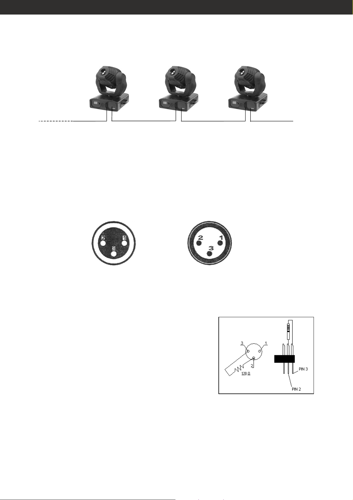
Proiettore 3
Indirizzo 29
I cavi DMX non devono venire a contatto con altri cavi, in tal caso infatti gli apparecchi potrebbero non
funzionare correttamente o non funzionare affatto.
Usare solo cavi DMX con spina e presa tipo XLR 3 poli, per la connessione alla centralina DMX o per il
collegamento tra apparecchi.
Schema di connessione dei cavi DMX:
DMX-output
presa XLR
Proiettore 2
Indirizzo 15
Proiettore 1
Indirizzo 1
DMX-512 Controller
DMX-input
spina XLR
1: terra
2: segnale (-)
3: segnale (+)
1: terra
2: segnale (-)
3: segnale (+)
Utilizzando centraline DMX con questo schema per i connettori, è possibile connettere l’uscita DMX
della centralina all’ingresso DMX del primo proiettore della catena DMX. Se si desidera connettere una
centralina DMX con un altro tipo di uscita XLR (es. 5 poli), è necessario disporre di un adattatore.
ATTENZIONE:
Per installazioni dove il cavo di segnale deve percorrere
lunghe distanze o dove vi sono disturbi elettrici, per esempio
in discoteca, è consigliato l’uso di una terminazione DMX. Il
terminatore DMX è semplicemente un connettore XLR con
collegato ad esso una resistenza da 120Ω (Ohm) tra i piedini
2 e 3. La resistenza viene innestata nella presa DIGITAL THRU
dell’ultimo proiettore della catena. La connessione è
illustrata a destra.
5
Page 6

MESSA IN FUNZIONE
Dopo aver connesso il proiettore alla rete di alimentazione, esso può essere acceso.
Ogni proiettore può occupare al massimo 14 canali DMX. Per fare in modo che il segnale di controllo sia
correttamente ricevuto da ogni PLML575SCNXP, è necessario che ognuno di essi sia indirizzato. Questo
può essere fatto per ogni singolo proiettore cambiando le configurazioni del display, come indicato di
seguito.
Assicurarsi che non ci sia nessuna sovrapposizione tra canali per ottenere un controllo corretto ed
indipendente per ogni apparecchio della catena. Se due, tre o più proiettori hanno lo stesso indirizzo
DMX, questi lavoreranno all’unisono.
Dopo aver indirizzato tutti i proiettori, essi potranno essere controllati attraverso la centralina DMX.
NOTE:
Immediatamente dopo l’accensione il proiettore rileva se il segnale DMX-512 è ricevuto o meno. Se non
viene ricevuto alcun segnale, tale situazione potrebbe essere provocata dal fatto che:
- il cavo DMX proveniente dalla centralina non è connesso al proiettore
- la centralina è spenta o difettosa
- il cavo o il connettore DMX sono difettosi
- il segnale del cavo risulta invertito sul connettore d’ingresso.
IMPOSTAZIONI DEL MENU
Su ogni proiettore è presente un display LCD ed una manopola per selezionare le impostazioni di menù.
Ruotare e premere per selezionare.
1. VERSION: per evidenziare il marchio, il modello, la versione, numero di serie, ore di funzionamento
della lampada, ore di funzionamento del proiettore.
2. DMX ADDRESS: per impostare l’indirizzo del proiettore.
3. PAN REVERSE: On (pan invertito) – Off (pan normale).
4. TILT REVERSE: On (tilt invertito) – Off (tilt normale).
5. PAN/TILT SPEED: per selezionare tra 00 e 15 la velocità del pan e del tilt.
6. PAN/TILT MODE: per impostare la modalità 8 bit o 16 bit. Quando è impostata la modalità 8 bit i
canali Pan fine e Tilt fine sono disabilitati e il testa mobile ha 12 canali DMX.
7. LAMP MODE: On (no controllo via DMX) – Off (controllo via DMX)
6
Page 7

8. RESET: per resettare il proiettore:
- Time restore (per reimpostare le ore di funzionamento dopo aver inserito una password per evitare
modifiche non autorizzate);
- Motor restore (per resettare i motori dopo aver inserito una password per evitare modifiche non
autorizzate).
9. CHANNEL TEST: per impostare manualmente i valori dei canali, quando il proiettore non è connesso
ad una linea DMX:
- 01: Pan
- 02: Tilt
- 03: Pan fine
- 04: Tilt fine
- 05: Pan/Tilt speed
- 06: Lamp/Reset
- 07: Color wheel
- 08: Gobo wheel
- 09: Rotazione gobo
- 10: Focus
- 11: Prisma
- 12: Rotazione prisma
- 13: Strobo
- 14: Dimmer
- 15÷16: non utilizzato
- 17: uscita
10. DISPLAY: per impostare varie modalità del display:
- Language: per selezionare la lingua tra inglese e cinese;
- Backlight time: per selezionare il tempo di permanenza dell’illuminazione del display tra
(sempre acceso) e 30 secondi;
- Back brightness: per impostare l’intensità della retroilluminazione del display tra 0 (min) e 5 (max).
11. MOTOR ADJUST: per regolare lo zero dei motori colori, gobo, rotazione gobo, prisma, rotazione
prisma, messa a fuoco e strobo. Effettuata la regolazione è possibile salvare (tramite password per
evitare modifiche non autorizzate).
12. CONTROL: per impostare differenti modalità di funzionamento:
- Control: per scegliere tra le modalità DMX, Automatica, Musicale e Slave
- Run: per scegliere il programma da eseguire se in modalità non DMX
- Speed: per impostare la velocità di esecuzione del programma.
13. HELP INFO: per visualizzare informazioni di copyright, costruttore ecc.
14. EXIT
open
7
Page 8
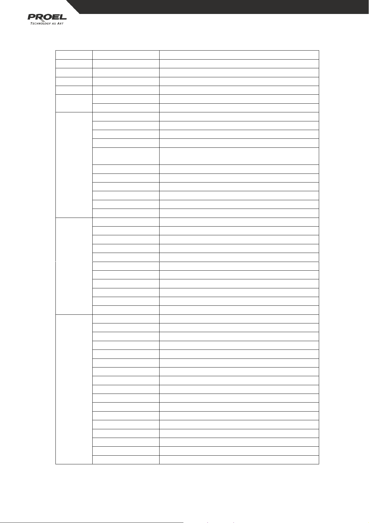
CANALI DMX (modalità 16 bit)
Canale Valore Funzione
CH 1 000 – 255 Pan 0° - 540°
CH 2 000 – 255 Tilt 0° - 280°
CH 3 000 – 255 Pan fine
CH 4 000 – 255 Tilt fine
CH 5
000 – 225 Velocità Pan/Tilt da max a min
226 - 255 Velocità Pan/Tilt da min a max
000 – 151 Nessuna funzione
152 – 159 Otturatore chiuso durante il cambio dei colori
160 – 167 Otturatore chiuso durante il cambio dei gobos
168 – 183 Nessuna funzione
184 – 191 Otturatore chiuso durante il cambio dei colori e
CH 6
192 – 199 Nessuna funzione
200 – 207 Spegnimento lampada dopo 3 secondi
208 – 215 Accensione lampada dopo 3 secondi
216 – 239 Nessuna funzione
240 – 247 Reset
248 – 255 Nessuna funzione
000 – 007 Aperto
008 – 015 Magenta
016 – 023 Giallo
024 – 031 Arancio
032 – 039 Verde
CH 7
040 – 047 Rosso
048 – 055 Blu
056 – 063 Porpora
064 – 191 ½ colore
192 – 223 Rainbow da lento a veloce
224 - 255 Rainbow inverso da lento a veloce
000 – 007 Bianco
008 – 015 Gobo 1
016 – 023 Gobo 2
024 – 031 Gobo 3
032 – 039 Gobo 4
040 – 047 Gobo 5
048 – 055 Gobo 6
056 – 063 Gobo 7
CH 8
064 – 079 Shacking gobo 7 da lento a veloce
080 – 095 Shacking gobo 6 da lento a veloce
096 – 111 Shacking gobo 5 da lento a veloce
112 – 127 Shacking gobo 4 da lento a veloce
128 – 143 Shacking gobo 3 da lento a veloce
144 – 159 Shacking gobo 2 da lento a veloce
160 – 175 Shacking gobo 1 da lento a veloce
176 – 191 Shacking bianco da lento a veloce
192 - 255 Rainbow da lento a veloce
dei gobos
8
Page 9
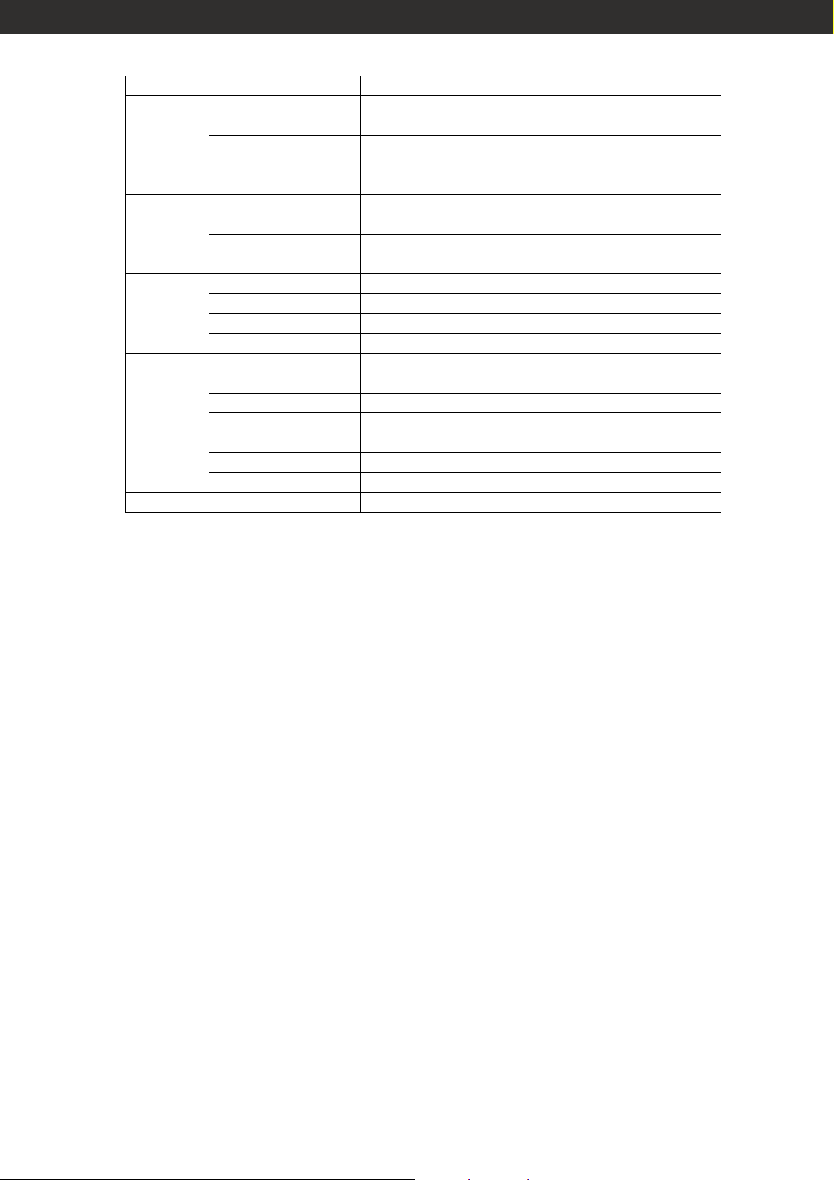
Canale Valore Funzione
000 – 159 Rotazione gobo col movimento dello slider
160 – 191 Shacking crescente in ampiezza e velocità
CH 9
192 – 223 Rotazione gobo con velocità crescente
224 – 255 Rotazione inversa gobo con velocità
decrescente
CH 10 000 - 255 Focus
000 – 007 Nessuna funzione
CH 11
008 – 063 Prisma
064 – 255 Macro
000 – 159 Rotazione prisma col movimento dello slider
CH 12
190 – 191 Shacking crescente in ampiezza e velocità
192 – 223 Rotazione prisma da lenta a veloce
224 – 255 Rotazione inversa prisma da lenta a veloce
000 – 015 Nessuna funzione
016 – 047 Open
048 – 095 Strobo da lento a veloce
CH 13
096 – 143 Effetto pulsante in apertura da lento a veloce
144 – 191 Effetto pulsante in chiusura da lento a veloce
192 – 239 Strobo casuale
240 – 255 Open
CH 14 000 - 255 Dimmer 0 – 100%
9
Page 10

MANUTENZIONE
Per mantenere elevata la qualità delle prestazioni del PLML575SCNXP, è fondamentale una pulizia
regolare degli elementi dell’asse ottico, così come dei fori di aerazione e della ventola di
raffreddamento.
Importante! Polvere eccessiva, depositi di fumo ed altre scorie riducono le prestazioni e causano
surriscaldamento. Questo tipo di danni non è coperto da garanzia.
Pulizia di fori di aerazione e ventola di raffreddamento:
Per mantenere efficiente il sistema di raffreddamento, la polvere deve essere periodicamente pulita dai
fori di aerazione e dalla ventola di raffreddamento. Rimuoverla con una spazzola morbida, con un panno
di cotone, con un aspirapolvere o con aria compressa.
Pulizia dei componenti ottici:
Pulire i componenti ottici regolarmente. La presenza di macchie o polvere sulle superfici ottiche può
ridurre la resa luminosa e la qualità degli effetti.
Prestare molta attenzione durante la pulizia dei componenti ottici ed assicurarsi di lavorare in un
ambiente pulito e ben illuminato. Non usare solventi che potrebbero danneggiare la plastica o le
superfici verniciate.
- Staccare l’apparecchiatura dalla corrente e lasciarla raffreddare.
- Rimuovere il coperchio superiore.
- Aspirare o soffiare via delicatamente con aria compressa polvere ed altre particelle depositatesi.
- Rimuovere le particelle rimaste attaccate con un tessuto privo di filamenti o con un panno di cotone
inumidito con pulitore per vetri o acqua distillata. Non sfregare le superfici: tirare via le particelle con
una pressione leggera e ripetuta.
- Rimuovere fumo ed altri residui con un panno di cotone o con un tessuto privo di filamenti
inumidito con alcol isopropile. Si può utilizzare anche un comune pulitore per vetri, ma i residui
devono essere eliminati con acqua distillata. Pulire con un movimento lento e circolare, andando dal
centro verso l’esterno. Asciugare con un panno pulito, soffice e privo di filamenti, oppure con aria
compressa.
- Chiudere il coperchio dell’apparecchiatura e stringere le viti di chiusura, facendo attenzione a non
intrappolare nessun filo pendente.
DATI TECNICI
PLML575SCNXP
Alimentazione: 230V – 50Hz
Consumo: 750W
Lampada: HMI 575W/S
Dimensioni: LxPxH mm.490x470x565
Peso: kg. 26
10
Page 11

MAIN GUIDELINES
- Warning! This product is not for household use.
- Read this manual before powering or installing the fixture, follow the safety precautions listed below
and observe all warnings in this manual and printed on the fixture. If you have questions about how
to operate the fixture safely, please contact a PROEL distributor for assistance. Refer any service
operation not described in this manual to a qualified technician.
- Do not modify the fixture or install other than genuine PROEL accessories and upgrade kits.
- Refer servicing to qualified personnel.
- Maximum ambient temperature Ta = 35°C.
- See serial label for replacement fuse size and lamp type.
- Suitable for mounting on normally flammable surfaces.
- Do not look directly into the light.
- Risk of fire, electrical shock and burns.
- For outdoor use.
- Do NOT block exhaust vents.
- Shields, lenses or ultraviolet screens shall be changed if they become visibly damaged to the extent
that their effectiveness is impaired, for example, by cracks or deep scratches.
- The lamp shall be changed if it becomes damaged or thermally deformed.
- If the external power cord of this luminaire is damaged, it shall be replaced by a special cord
exclusively available from your PROEL dealer.
- Warning always disconnect from mains power before replacing the lamp, fuses, or any part, and
when not in use.
- Before operation ensure that factory setting of voltage and frequency match local power supply.
- Always ground (earth) the fixture electrically.
- Use only a source of AC power that complies with local building and electrical codes and has both
overload and ground-fault protection.
- Never operate the fixture with missing or damaged lenses and/or covers.
- Warning Hot lamp. The exterior of the fixture can become hot. Allow to cool for at least 20 minutes
before handling or opening.
- Minimum distance to flammable material = 1 m.
- Minimum distance to illuminated surface = 2.5 m.
- Never attempt to bypass the thermostatic switch or fuses. Always replace defective fuses with ones
of the specified type and rating.
- Ensure that the air flow through vents is free and unobstructed.
- Provide a minimum clearance of 0.1 meters around air vents.
- Never place filters or other materials over the lens or in the optical path.
- The exterior of the fixture can become hot. Allow the fixture to cool for at least 20 minutes before
handling.
- Do not operate the fixture if the ambient temperature (Ta) exceeds 35° C.
- Do not stare directly into the light.
- Never operate the fixture without all lenses and covers installed: an unshielded lamp emits
dangerous UV radiation that can cause burns and eye damage.
11
Page 12

AC POWER
Before operation ensure that factory setting of voltage and frequency match local power supply.
Always ground (earth) the fixture electrically.
Use only a source of AC power that complies with local building and electrical codes and has both
overload and ground-fault protection.
If it is necessary to substitute power supply plug, connect it in accordance with the following code:
GREEN/YELLOW: Ground
BLUE: Neutral
BROWN: Live
WARNING: the luminaire must be earthed
Connect the mains power cable to the fixture at the 3-prong IEC male input socket at the rear of the
fixture.
- PLML575SCNXP is designed to be hung overhead with a clamp (not included).
- Warning! Block access below the work area before proceeding.
- Always use a secure means of secondary attachment (safety rope).
- Verify that the structure can support at least 10 times the weight of all installed fixtures, clamps,
cables, auxiliary equipment, and other items.
- If hanging the fixture with a rigging clamp, verify that the clamp is undamaged and is designed for
the fixture’s weight. Bolt the clamp securely to the mounting bracket on the fixture with a grade 8.8
(minimum) M12 bolt and lock nut, or as recommended by the clamp manufacturer, through the
clamp hole in the mounting bracket.
- If permanently installing the fixture, verify that the hardware (not included) and mounting surface
can bear at least 10 times the fixture’s weight.
- Working from a stable platform, clamp or fasten the fixture to the structure.
- Install a safety cable that can hold at least 10 times the weight of the fixture through the safety cable
attachment point on the fixture.
- Loosen the swivel locks, tilt the fixture to the desired angle, and retighten.
- Verify that the fixture is at least 1 meter from any flammable surfaces.
- Verify that the clearance around the air vents is at least 0.1 meters.
OVERHEAD MOUNTING
12
Page 13
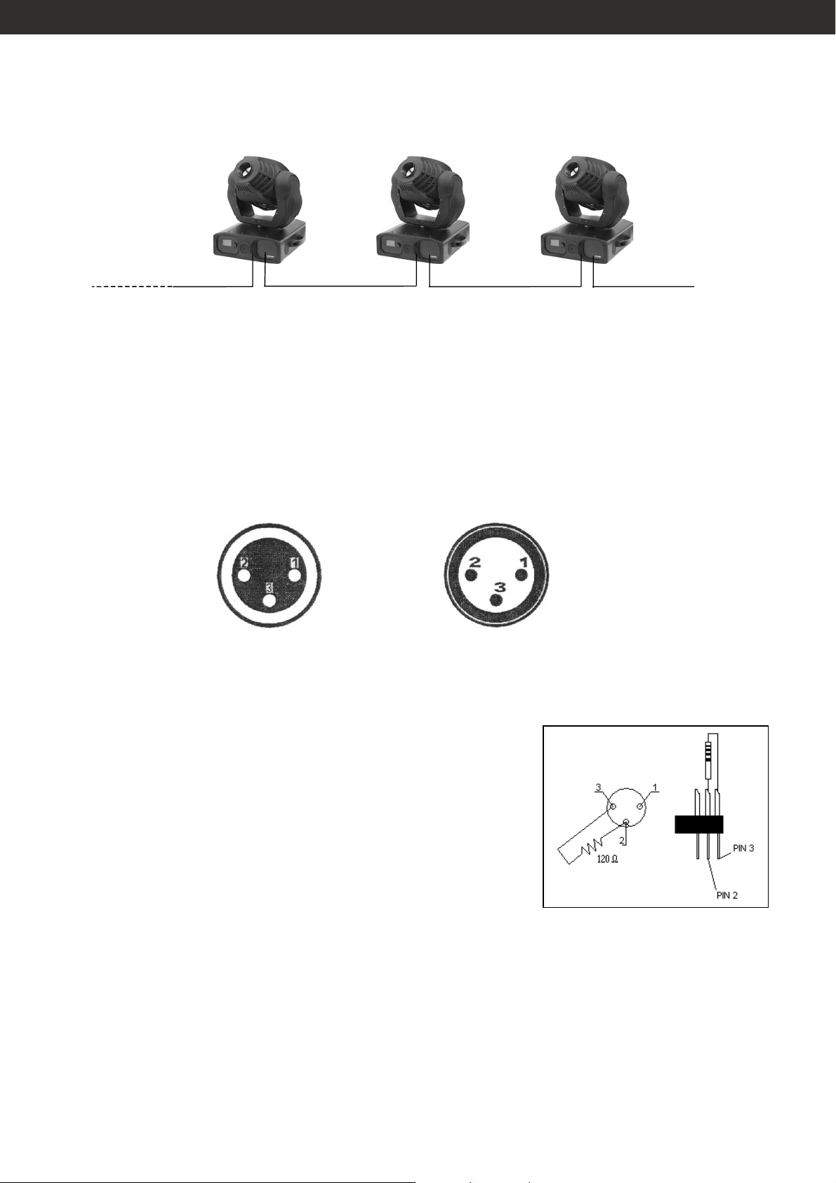
DMX-512 CONNECTION
Projector 3
Address 29
The wires must not come into contact with each other, otherwise the fixtures will not work at all, or not
will work properly.
Only use only a DMX cable and 3-pin XLR-plugs and connectors in order to connect the controller with
the fixture or one fixture with another.
Occupation of XLR-connection:
DMX-output
XLR mounting-socket
Projector 2
Address 15
Projector 1
Address 1
DMX-512 Controller
DMX-input
XLR mounting socket
1: ground
2: signal (-)
3: signal (+)
1: ground
2: signal (-)
3: signal (+)
If you are using controllers with this occupation, you can connect the DMX-output of the controller
directly with the DMX-input of the first fixture in the DMX-chain. If you wish to connect DMX-controllers
with other XLR-outputs, you need to use adapter-cables.
CAUTION:
For all installation, having long signal cables or in the presence of
electrical noise, for example a discotheque, it is recommended
practice to use a DMX terminator: this assist in preventing
corruption of the digital control signal by external noise. The DMX
terminator is simply an XLR connector with a 120Ω (Ohm) resistor
connected across pins 2 and 3, which is then plugged into the
DIGITAL THRU socket on the last projector in the chain. The
connections are illustrated on the right.
13
Page 14

OPERATION
After you connected the effect to the mains, the fixture starts running. During the reset, the motors are
trimmed and the device is ready for use afterwards.
Each projector occupies maximum 14 channels. To ensure that the control signals are properly directed
to each PLML575SCNXP, the projector requires addressing. This is to be done for every single projector
by changing the settings on the display.
Please make sure that you don’t have any overlapping channels in order to control each projector
correctly and independently from any other fixture on the DMX data link. If two, three or more projector
is addressed similarly, they will work similarly.
After having addressed all projectors, you may now start operating these via your lighting controller.
NOTE:
After switching on, the projector will automatically detect whether DMX 512 data is received or not. If
there is no data received at the DMX-input, this situation can occur if:
- the 3 PIN XLR plug is not connected with the input of the projector
- the controller is switched off or defective
- the cable or connector is defective
- the signal wires are swap in the input connector
MENU SETTINGS
The fixture is mounted with a LCD display and a rotating knob to select different settings.
Rotate and push to select.
1. VERSION: brand, model, version, number, lamp time, use time.
2. DMX ADDRESS: set address.
3. PAN REVERSE: On (reversed) Off (normal).
4. TILT REVERSE: On (reversed) Off (normal).
5. PAN/TILT SPEED: from 00-15, to set the speed for Pan/Tilt movement.
6. PAN/TILT MODE: 8bit, 16bit, when set as 8bit, the channels Pan fine and Tilt fine will be disabled, the
fixture has 12 channels now.
7. LAMP MODE: On (no control via DMX); Off (control via DMX)
14
Page 15

8. RESET: lighting reset:
- Time restore (can be set password afterwards to prevent unwanted modifying);
- Motor restore (can be set password afterwards to prevent unwanted modifying).
9. CHANNEL TEST: to set manually the values of DMX channels and internal programs, when the
projector is not connected to a DMX line:
- 01: Pan
- 02: Tilt
- 03: Pan fine
- 04: Tilt fine
- 05: Pan/Tilt speed
- 06: Lamp/Reset
- 07: Color wheel
- 08: Gobo wheel
- 09: Gobo rotation
- 10: Focus
- 11: Prism
- 12: Prism rotation
- 13: Shutter
- 14: Dimmer
- 15÷16: not used
- 17: exit
10. DISPLAY: to set different display modes:
- Language: select the language between english and chinese;
- Backlight time: open(always on ) - 30 seconds;
- Back brightness: 0-5, from dark to bright.
11. MOTOR ADJUST: 01:Color; 02:gobo;03:gobo rotate; 04:prism; 05: prism rotate; 06: focus;07:shutter;
08:save (can be set password afterwards to prevent unwanted modifying). 09: exit..
12. CONTROL: to set different working modes:
- Control: select between DMX, Auto, music, slave;
- Run: select the program you want to run in certain mode;
- Speed: set running speed for program.
13. HELP INFO: include copyright, company information, etc.
14. EXIT
15
Page 16
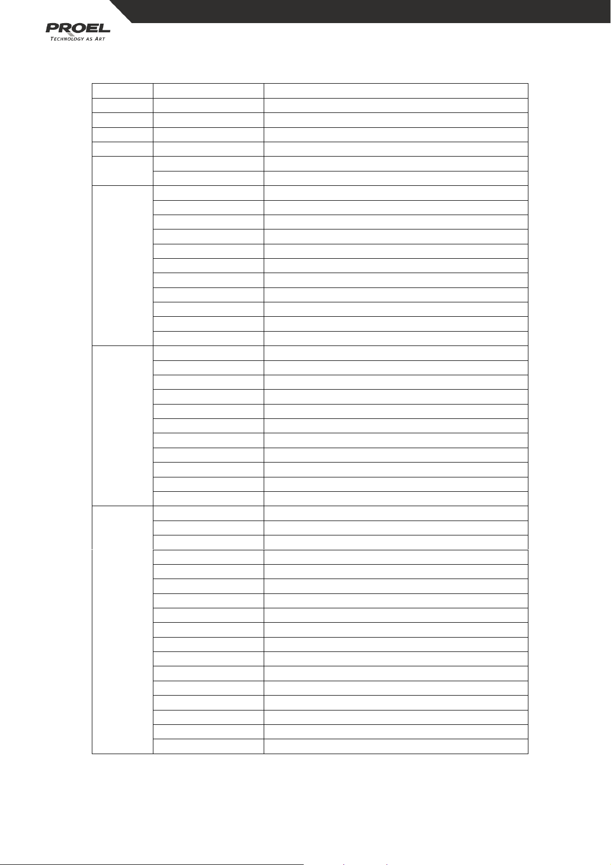
DMX CHANNELS (16 bit mode)
Channel Value Function
CH 1 000 – 255 Pan 0° - 540°
CH 2 000 – 255 Tilt 0° - 280°
CH 3 000 – 255 Pan fine
CH 4 000 – 255 Tilt fine
CH 5
000 – 225 Pan/Tilt speed from fast to slow
226 - 255 Pan/Tilt speed from slow to fast
000 – 151 No function
152 – 159 Shutter off when changing color
160 – 167 Shutter off when changing gobo
168 – 183 No function
184 – 191 Shutter off when changing color or gobo
CH 6
192 – 199 No function
200 – 207 Lamp off after 3s
208 – 215 Lamp on after 3s
216 – 239 No function
240 – 247 Reset
248 – 255 No function
000 – 007 Open
008 – 015 Magenta
016 – 023 Yellow
024 – 031 Orange
032 – 039 Green
CH 7
040 – 047 Red
048 – 055 Blue
056 – 063 Purple
064 – 191 ½ color
192 – 223 Forward rainbow from slow to fast
224 - 255 Backward rainbow from slow to fast
000 – 007 White
008 – 015 Gobo 1
016 – 023 Gobo 2
024 – 031 Gobo 3
032 – 039 Gobo 4
040 – 047 Gobo 5
048 – 055 Gobo 6
056 – 063 Gobo 7
CH 8
064 – 079 Shacking gobo 7 from slow to fast
080 – 095 Shacking gobo 6 from slow to fast
096 – 111 Shacking gobo 5 from slow to fast
112 – 127 Shacking gobo 4 from slow to fast
128 – 143 Shacking gobo 3 from slow to fast
144 – 159 Shacking gobo 2 from slow to fast
160 – 175 Shacking gobo 1 from slow to fast
176 – 191 Shacking white from slow to fast
192 - 255 Rainbow from slow to fast
16
Page 17
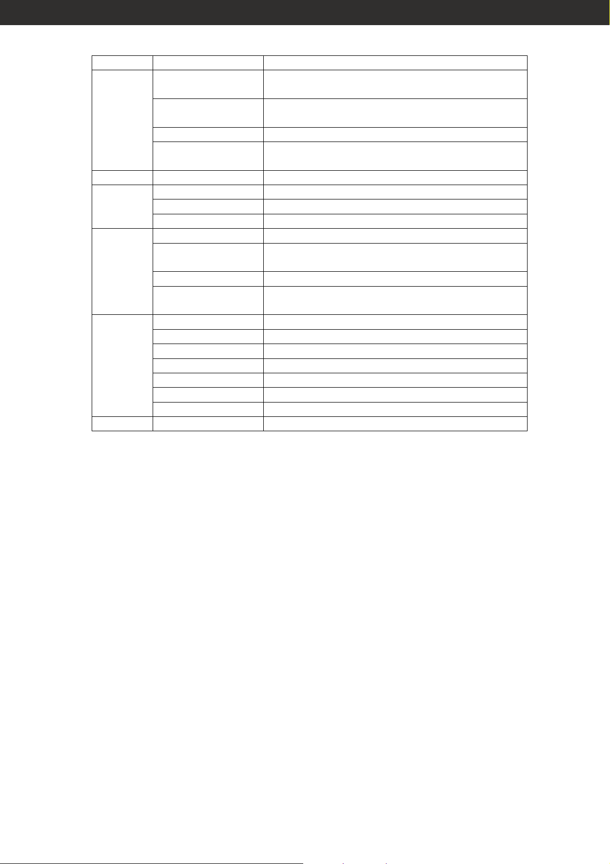
Canale Valore Funzione
000 – 159 Forwards gobo rotation with your pushing of
fader
160 – 191 Gobo shaking, increasing in amplitude and
CH 9
speed
192 – 223 Forwards gobo rotation with increasing speed
224 – 255 Backwards gobo rotation with decreasing
speed
CH 10 000 - 255 Focus
000 – 007 No function
CH 10
008 – 063 Prism
064 – 255 Macro
000 – 159 Prism rotation with your pushing of fader
190 – 191 Prism shaking, increasing in amplitude and
CH 11
192 – 223 Forwards prism rotation with increasing speed
speed
224 – 255 Backwards prism rotation with increasing
speed
000 – 015 Nessuna funzione
016 – 047 Open
048 – 095 Strobe from slow to fast
CH 13
096 – 143 Pulse effect, opening, increasing
144 – 191 Pulse effect, closing, increasing
192 – 239 Random strobe
240 – 255 Open
CH 14 000 - 255 Dimmer 0 – 100%
17
Page 18

BASIC SERVICE
Regular cleaning of the elements in the optical path, as well as the air vents, is vital to maintaining the
operational quality of the PLML575SCNXP.
Important! Excessive dust, smoke fluid, and particulate build-up degrades performance and causes
overheating and damage to the fixture that is not covered by the warranty.
Cleaning the air vents:
To maintain adequate cooling, dust must be cleaned from the air vents periodically. Remove dust from
the air vents with a soft brush, cotton swab, vacuum, or compressed air.
Cleaning optical components:
Clean the optical components regularly. The presence of smudges or dust on optical surfaces can
reduce the strength of the light output and the quality of the effects.
Use care when cleaning optical components and work in a clean, well lit area. The coated surfaces are
fragile and easily scratched. Do not use solvents that can damage plastic or painted surfaces.
- Disconnect the fixture from power and allow it to.
- Remove upper cover.
- Vacuum or gently blow away dust and loose particles with compressed air.
- Remove stuck particles with an unscented tissue or cotton swab moistened with glass cleaner or
distilled water. Do not rub the surface: lift the particles off with a soft repeated press.
- Remove smoke, and other, residues with cotton swabs or unscented tissues moistened with
isopropyl alcohol. A commercial glass cleaner may be used, but residues must be removed with
distilled water. Clean with a slow circular motion from center to edge. Dry with a clean, soft and lintfree cloth or compressed air.
- Close the fixture cover and tighten the thumb screw, taking care not to trap any loose wires.
TECHNICAL DATA
PLML575SCNXP
Power supply: 230V – 50Hz
Consumption: 750W
Led: HMI 575W/S
Dimensions: LxPxH mm.490x470x565
Weight: kg. 26
18
Page 19

19
Page 20

20 20
 Loading...