

MQ12USB
12 Channel Mixer
with Effect and USB
USER’S MANUAL
MANUALE D’USO
96MAN0135-R E V. 30/18
ENGLISH
ITALIANO

2
SUMMARY - ENGLISH
DISPOSAL OF OLD ELECTRICAL & ELECTRONIC EQUIPMENT ................................................................. 4
GENERAL SAFETY INSTRUCTIONS .......................................................................................................... 4
IN CASE OF FAULT ................................................................................................................................... 4
PACKAGING, SHIPPING AND COMPLAINT .............................................................................................. 4
WARRANTY AND PRODUCTS RETURN ................................................................................................... 4
MAINTENANCE AND DISCLAIMER .......................................................................................................... 5
POWER SUPPLY ...................................................................................................................................... 5
CONFORMITY ......................................................................................................................................... 5
INTRODUCTION ...................................................................................................................................... 6
DESCRIPTION .......................................................................................................................................... 6
INSTRUCTIONS ....................................................................................................................................... 6
1. MIC-XLR / LINE-JACK combo input (ch. 1 ÷ 4) ............................................................................. 6
2. LO CUT switch (ch. 1 ÷ 4) ............................................................................................................. 8
3. CHANNEL GAIN control (ch. 1 ÷ 4 / 5 ÷ 8) ................................................................................... 8
4. COMP compressor control (ch. 1 ÷ 4) ......................................................................................... 8
5. COMP indicator (ch. 1 ÷ 4) .......................................................................................................... 8
6. EQ section HIGH control (ch. 1 ÷ 4 / 5 ÷ 8 / 9 ÷ 12) .................................................................... 8
7. EQ section MID control (ch. 1 ÷ 4 / 5 ÷ 8) ................................................................................... 8
8. EQ section LOW control (ch. 1 ÷ 4 / 5 ÷ 8 / 9 ÷ 12) ..................................................................... 8
9. AUX 1 send control (pre/post) (ch. 1 ÷ 4 / 5 ÷ 8 / 9 ÷ 12) ........................................................... 8
10. POST switch (ch. 1 ÷ 4 / 5 ÷ 8 / 9 ÷ 12) .................................................................................... 8
11. AUX2/FX send control (ch. 1 ÷ 4 / 5 ÷ 8 / 9 ÷ 12) .................................................................... 9
12. PAN control (ch. 1 ÷ 4) ............................................................................................................. 9
13. MUTE switch/LED (ch. 1 ÷ 4 / 5 ÷ 8 / 9 ÷ 12) ........................................................................... 9
14. MIX/GRP 1-2 bus switch (ch. 1 ÷ 4 / 5 ÷ 8 / 9 ÷ 12) ................................................................. 9
15. CHANNEL FADER level control (ch. 1 ÷ 4 / 5 ÷ 8 / 9 ÷ 12) ....................................................... 9
16. PEAK/PFL detector (ch. 1 ÷ 4 / 5 ÷ 8 / 9 ÷ 12) ......................................................................... 9
17. PFL switch (ch. 1 ÷ 4 / 5 ÷ 8 / 9 ÷ 12) ....................................................................................... 9
18. MIC-XLR / LINE-JACK L MONO combo input (ch. 5 ÷ 8) .......................................................... 9
19. LINE-JACK R Input (ch. 6 / 8) .................................................................................................... 9
20. BAL control (ch. 5 ÷ 8 / 9 ÷ 12) .............................................................................................. 10
21. LINE LEFT/MONO jack input (ch. 9 ÷ 12) ............................................................................... 10
22. LINE R jack input (ch. 10 / 12) ............................................................................................... 10
23. LINE RCA L & R inputs (ch. 9 ÷ 12) ......................................................................................... 10
24. LINE/USB switch (ch. 11-12) .................................................................................................. 10
25. FX MUTE pedal jack input ...................................................................................................... 10
26. FX PRESETS selector ............................................................................................................... 10
27. FX DISPLAY number ............................................................................................................... 11
28. EFFECT MUTE button ............................................................................................................. 11
29. EFFECT PEAK/MUTE detector ................................................................................................ 11
30. FX FADER level control ........................................................................................................... 11
31. AUX 1 SEND level control ...................................................................................................... 11
32. AUX 1 SEND jack output ........................................................................................................ 11
33. AUX 2 / FX SEND level control ............................................................................................... 11
34. AUX 2 SEND jack output ........................................................................................................ 11

3
35. MAIN MIX to C.ROOM switch ................................................................................................ 12
36. GROUP 1-2 to C.ROOM switch .............................................................................................. 12
37. PHONES level control ............................................................................................................ 12
38. PHONES stereo jack output ................................................................................................... 12
39. C.ROOM level control ............................................................................................................ 12
40. C.ROOM L & R jack output .................................................................................................... 12
41. GROUPS 1-2 FADER level control ........................................................................................... 12
42. GROUPS 1-2 jack output ........................................................................................................ 12
43. TO MIX switch ........................................................................................................................ 12
44. MAIN MIX FADER level control .............................................................................................. 12
45. PFL ACTIVE LED ...................................................................................................................... 12
46. L & R LEVEL meters ................................................................................................................ 13
47. MAIN MIX L & R XLR output balanced .................................................................................. 13
48. MAIN MIX L & R jack output balanced .................................................................................. 13
49. +48V phantom switch and LED .............................................................................................. 13
50. ON LED ................................................................................................................................... 13
51. USB PORT socket ................................................................................................................... 13
52. POWER switch ....................................................................................................................... 13
53. AC~ socket ............................................................................................................................. 14
54. FUSE holder ........................................................................................................................... 14
TECHNICAL SPECIFICATION .................................................................................................................. 14
Mechanical Dimensions ....................................................................................................................... 28
Configurations Example ....................................................................................................................... 29
Accessories ........................................................................................................................................... 30
Connectors ........................................................................................................................................... 31

4
DISPOSAL OF OLD ELECTRICAL & ELECTRONIC EQUIPMENT
This marking shown on the product or its literature, indicates that it should not be disposed with
other household wastes at the end of its working life. To prevent possible harm to the
enviroment or human health from uncontrolled waste disposal, please separate this from other
types of wastes and recycle it responsibly to promote the sustainable reuse of material resources.
Household users should contact either the retailer where they purchased this product, or their
local government office, for details of where and how they can take this item for environmentally safe
recycling. Business users should contact their supplier and check the terms and conditions of the purchase
contract. This product should not be mixed with other commercial wastes for disposal.
GENERAL SAFETY INSTRUCTIONS
• CAUTION - Before using this product read carefully the following safety instructions. Take a look of this
manual entirely and preserve it for future reference. When using any electric product, basic precautions
should always be taken, including the following:
• To reduce the risk, close supervision is necessary when the product is used near children.
• Protect the apparatus from atmospheric agents and keep it away from water, rain and high humidity places.
• This product should be site away from heat sources such as radiators, lamps and any other device that generate heat.
• Care should be taken so that objects and liquids do not go inside the product.
• The product should be connected to a power supply only of the type described on the operating
instructions or as marked on the product.
IN CASE OF FAULT
• In case of fault or maintenance this product should be inspected only by qualified service personnel when:
• Liquids have spilled inside the product.
• The product has fallen and been damaged.
• The product does not appear to operate normally or exhibits a marked change in performance.
• Do not operate on the product, it has no user-serviceable parts inside.
• Refer servicing to an authorized maintenance center.
PACKAGING, SHIPPING AND COMPLAINT
• This unit package has been submitted to ISTA 1A integrity tests. We suggest you control the unit
conditions immediately after unpacking it.
• If any damage is found, immediately advise the dealer. Keep all unit packaging parts to allow inspection.
• Proel is not responsible for any damage that occurs during shipment.
• Products are sold “delivered ex warehouse” and shipment is at charge and risk of the buyer.
• Possible damages to unit should be immediately notified to forwarder. Each complaint for manumitted
package should be done within eight days from product receipt.
WARRANTY AND PRODUCTS RETURN
• Proel products have operating warranty and comply their specifications, as stated by manufacturer.
• Proel warrants all materials, workmanship and proper operation of this product for a period of two years
from the original date of purchase. If any defects are found in the materials or workmanship or if the
product fails to function properly during the applicable warranty period, the owner should inform about
these defects the dealer or the distributor, providing receipt or invoice of date of purchase and defect

5
detailed description. This warranty does not extend to damage resulting from improper installation,
FCC COMPLIANCE NOTICE
This device complies with part 15 of the FCC rules. Operation is subject to the following two conditions:
CAUTION: Changes or modifications not expressly approved by the party responsible for compliance could void the user’s
orrect the interference by one or more of the following
misuse, neglect or abuse. Proel S.p.A. will verify damage on returned units, and when the unit has been
properly used and warranty is still valid, then the unit will be replaced or repaired. Proel S.p.A. is not
responsible for any "direct damage" or "indirect damage" caused by product defectiveness.
MAINTENANCE AND DISCLAIMER
• Clean only with dry cloth.
• Proel products have been expressly designed for audio application, with signals in audio range (20Hz to
20kHz). Proel has no liability for damages caused in case of lack of maintenance, modifications, improper
use or improper installation non-applying safety instructions.
• Proel S.p.A. reserves the right to change these specifications at any time without notice.
• Proel S.p.A. declines any liability for damages to objects or persons caused by lack of maintenance,
improper use, installation not performed with safety precautions and at the state of the art.
POWER SUPPLY
• This apparatus should only be connected to power source type specified in this owner’s manual or on the unit.
• If the supplied AC power cable plug is different from the wall socket, please contact an electrician to
change the AC power plug.
• Hold the plug and the wall outlet while disconnecting the unit from AC power.
• If the unit will not be used for a long period of time, please unplug the power cord from AC power outlet.
• To avoid unit power cord damage, please do not strain the AC power cable and do not bundle it, do not
step on it or pinch it by heavy objects.
• The mains plug is used as disconnect device, the disconnect device shall remain readily operable.
CONFORMITY
• The product is in compliance with CE Directive LVD 2014 / 35 / CE as stated in EN 60065 standard.
• The product is in compliance with CE Directive EMC 2014 / 30 / CE as stated in EN 55103-1 and EN
55103-2 standards.
(1) This device may not cause harmful interference, and
(2) This device must accept any interference received, including interference that may cause undesired operation.
authority to operate the equipment.
NOTE: This equipment has been tested and found to comply with the limits for a Class B digital device, pursuant to part 15 of the
FCC Rules. These limits are designed to provide reasonable protection against harmful interference in a residential installation. This
equipment generates, uses, and can radiate radio frequency energy and, if not installed and used in accordance with the instruction
manual, may cause harmful interference to radio communications. However, there is no guarantee that interference will not occur in
a particular installation. If this equipment does cause harmful interference to radio or television reception, which can be determined
by turning the equipment off and on, the user is encouraged to try to c
measures:
• Reorient or relocate the receiving antenna.
• Increase the separation between the equipment and receiver.
• Connect the equipment into an outlet on a circuit different from that to which the receiver is connected.
• Consult the dealer or an experienced radio/TV technician for help.

6
INTRODUCTION
Thank you for choosing this PROEL product and for your trust in our brand, synonymous of professionalism,
accuracy, high quality and reliability. All our products are CE approved and designed for continuous use in
professional applications.
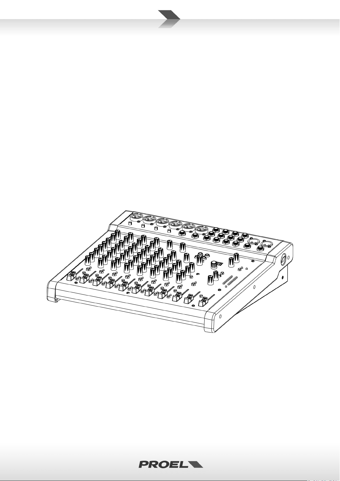
DESCRIPTION
MQ is a series of mixers created by PROEL to offer in a very compact and stylish package a high input density,
a full set of features and a superior audio quality, at a very convenient price point. The MQ series includes 5
models with 6, 10, 12 and 16 inputs, able to satisfy most of the sound reinforcement applications. Carefully
designed and engineered in Italy by PROEL R&D, MQ mixers are hosted in ultra-rugged cases, providing
extended durability for a stage-proof use.
The smallest models of the series, MQ6 and MQ6FX, offer in an ultra-compact format the performance of
professional consoles, delivering a clean and accurate sound. The MQ6FX, despite its small size, includes a
high-quality 24-bit DSP able to provide musicians and performers with studio-grade effects.
MQ10FX, together with 3-band EQ and one-knob intelligent COMPRESSORS, offers also 100 DSP presets with
a convenient LED display for the selection.
MQ12USB additional features include an USB audio I/O interface and extended mixing capability with
MONITOR send, STEREO GROUP bus and 45mm control faders.
The top-of-the-line MQ16USB feature 16 inputs and 12 microphone channels together with sweep mids and
one-knob intelligent COMPRESSORS on mono channels, 4 AUX sends, STEREO GROUP bus and 60mm control
faders.
Optional padded carrying bags and metal brackets for 19” rack mounting are available for selected models.
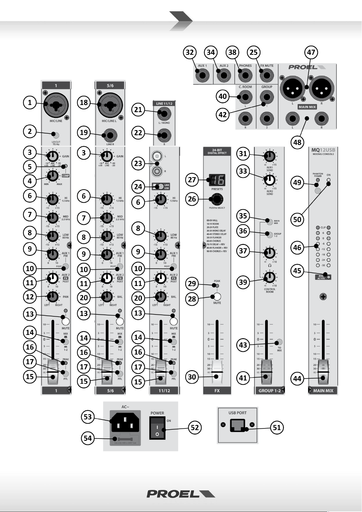
INSTRUCTIONS
1. MIC-XLR / LINE-JACK combo input (ch. 1 ÷ 4)
This is a female MIC-XLR / LINE-JACK combo connector that accepts a balanced microphone XLR input from
almost any type of microphone, or a balanced or unbalanced line level JACK input signal from almost any line
source.
The MIC-XLR input is wired as follows:
Pin 1 = shield or ground
Pin 2 = + positive or "hot"
Pin 3 = - negative or "cold"
The LINE-JACK input is wired as follows:
Tip = + positive or "hot"
Ring = - negative or "cold"
Sleeve = shield or ground
When connecting an unbalanced signal, wire them as follows:
Pin2 / Tip = + positive or "hot"
Pin 1-3 / Sleeve = shield or ground
7

8
2. LO CUT switch (ch. 1 ÷ 4)
This switch cuts bass frequencies below 75 Hz at a rate of 18 dB per octave. We recommend that you use the
LO CUT filter on every microphone application except kick drum, bass guitar, bassy synth patches or
recordings. These aside, there isn’t much down there that you want to hear and filtering it out makes the low
stuff you do want much more crisp and tasty. Not only that, but the LO CUT filter can help reduce the
possibility of feedbacks in live situations and it helps to conserve the amplifier power. Another way to use the
LO CUT filter is in combination with the LOW EQ on vocals during live performances. Many times, bass
shelving EQ can really benefit voices. Trouble is, adding LOW EQ also boosts stage rumble, mic handling
clunks, and breath pops.
3. CHANNEL GAIN control (ch. 1 ÷ 4 / 5 ÷ 8)
The gain control adjusts the input sensitivity of the mic and line inputs. This allows the signal from mics and
instruments to be adjusted to optimal internal levels. If the signals are plugged into the XLR input there is a 0
dB of gain with the knob turned all way down, rising up to 40 dB of gain fully up. When connected to the jack
input of any channels, there is 20 dB of attenuation all way down and 20 dB of gain fully up.
4. COMP compressor control (ch. 1 ÷ 4)
Each mono channel features a single-control compressor, able to adjust the overall dynamic range of the signal and to
increase its loudness. When rotating the control to the right, the loudest signals are reduced in order to avoid clipping,
while the quietest parts are boosted, producing a smooth, unified sound with no excessive peaks or distortion.
NOTE: avoid setting the compression too high, as the higher average output level that results may lead to
feedback.
5. COMP indicator (ch. 1 ÷ 4)
The COMP LED lights when the signal compression effect is engaged (it depends on the position of the
control and on the audio signal level).
6. EQ section HIGH control (ch. 1 ÷ 4 / 5 ÷ 8 / 9 ÷ 12)
This control gives you up to 15dB boost or cut at 12KHz with a “SHELVING” curve shape. Use it to increase or
reduce the sound “clarity” or “brightness”.
7. EQ section MID control (ch. 1 ÷ 4 / 5 ÷ 8)
This control gives you up to 15 dB boost or cut at 2.5 KHz with a “PEAKING” curve shape. Use it to increase or
reduce the sound “presence”.
8. EQ section LOW control (ch. 1 ÷ 4 / 5 ÷ 8 / 9 ÷ 12)
This control gives you up to 15dB boost or cut at 80Hz with a “SHELVING” curve shape. Use it to increase or
reduce the sound “punch”.
9. AUX 1 send control (pre/post) (ch. 1 ÷ 4 / 5 ÷ 8 / 9 ÷ 12)
This control sends the signal to the AUX 1 output. This signal is normally pre-fader, but it could be set postfader pressing the POST switch: in this case the signal level depends on the position of the channel FADER.
10. POST switch (ch. 1 ÷ 4 / 5 ÷ 8 / 9 ÷ 12)
Push this switch to set the AUX 1 control post-fader or release it to set the AUX 1 pre-fader. The pre-fader
setting is preferable if you want to use the AUX 1 send as stage monitor, in order to have your stage mix
independent from MAIN MIX.

9
11. AUX2/FX send control (ch. 1 ÷ 4 / 5 ÷ 8 / 9 ÷ 12)
This control sends the signal to the AUX 2 output and to the internal Digital Effect Processor. This signal is
post-fader or, in other words, it depends on the position of the channel's FADER.
12. PAN control (ch. 1 ÷ 4)
It adjusts the amount of channel signal sent to the left versus the right outputs. Use it to position the sound
origin in a panoramic stereo scene.
13. MUTE switch/LED (ch. 1 ÷ 4 / 5 ÷ 8 / 9 ÷ 12)
When you engage a channel’s mute switch, its signal disappears from these outputs: MAIN MIX, GROUPS 1-2,
AUX 1, AUX 2/FX.
NOTE: the input channel signal is not completely muted by this switch, so you can listen to it thru headphones
and C.ROOM outputs acting on the PFL button.
14. MIX/GRP 1-2 bus switch (ch. 1 ÷ 4 / 5 ÷ 8 / 9 ÷ 12)
Typically with this switch dis-engaged (up position) you assign the channel signal to the MAIN MIX bus,
regulated by the correspondent FADER, and you send it to the MAIN MIX output.
Engaging this switch (down position) you assign the channel signal to the GROUP 1-2 bus, regulated by the
GROUP 1-2 faders. You can use the GROUP 1-2 jacks as separate outputs or, engaging the switch TO MIX, to
create a submix for a set of channels (all the drums channels, for instance): in this case you can control the
assigned GROUP 1-2 signals together and independently from the rest of the mix.
15. CHANNEL FADER level control (ch. 1 ÷ 4 / 5 ÷ 8 / 9 ÷ 12)
It adjusts the level of the channel signal and send it to the MAIN MIX and/or to the GROUPS 1-2 buses.
16. PEAK/PFL detector (ch. 1 ÷ 4 / 5 ÷ 8 / 9 ÷ 12)
This LED has two functions:
• If the PEAK LED lights permanently this means that you have activated the PFL switch of this channel.
• If the PEAK LED flashes this means that the input signal is near to the CLIPPING point.
IMPORTANT: if the LED PEAK flashes reduce the level of the input signal using the GAIN control.
17. PFL switch (ch. 1 ÷ 4 / 5 ÷ 8 / 9 ÷ 12)
PFL is the abbreviation of Pre-Fader Listening, so this switch allows you to hear signals through your
headphones or control room outputs and to display the level on LED meters. Use the PFL in live sets to prelisten channels before they are fed into the mix or just to check out a particular channel anytime during a
session. You can PFL as many channels at a time as you like.
18. MIC-XLR / LINE-JACK L MONO combo input (ch. 5 ÷ 8)
This is a female JACK/XLR combo connector that accepts a balanced microphone XLR input from almost any
type of microphone or a balanced or unbalanced line level JACK input signal from almost any line source. If
the LINE R jack is not inserted, this channel operates like a MONO channel with this input as a single signal
source. Wiring is the same of previous paragraphs.
19. LINE-JACK R Input (ch. 6 / 8)
This is a JACK connector that accepts a balanced or unbalanced line level input signal from almost any line
source. This is used only in presence of LINE L jack input to use the channel as STEREO.

10
20. BAL control (ch. 5 ÷ 8 / 9 ÷ 12)
It adjusts the amount of channel signal sent to the left versus the right outputs if the channel is used as
MONO, or it fades the LEFT or RIGHT signal amount if the channel is used as STEREO.
21. LINE LEFT/MONO jack input (ch. 9 ÷ 12)
This is a female JACK connector that accepts a balanced or unbalanced line level input signal from almost any
line source. If the RIGHT jack is not inserted, this channel operates as a MONO channel with this input as a
single signal source. Wiring is the same of previous paragraphs.
22. LINE R jack input (ch. 10 / 12)
This is a JACK connector that accepts a balanced or unbalanced line level input signal from almost any line
source. This is used only in presence of LEFT jack input to use the channel as STEREO.
23. LINE RCA L & R inputs (ch. 9 ÷ 12)
These RCA inputs can be used instead of the jack inputs: they accept an unbalanced line level input signal
from almost any line source.
24. LINE/USB switch (ch. 11-12)
This button switches the channel input between the analog jack inputs or the USB audio playback from a PC
connected to the rear USB port.
25. FX MUTE pedal jack input
You can connect a footswitch (normally open) to MUTE the internal effect (suggested footswitch is PROEL
model GF29).
26. FX PRESETS selector
The internal Digital Effect Processor is built around a powerful 24bit DSP. It includes 100 different presets of
studio-grade effect algorithm.
HOW TO USE THE FX:
- rotate the SELECTOR knob (26) to choose the type of effect (preset) you want to use; rotating the knob the
number on the display scrolls and flashes. After you have chosen the effect, press the SELECTOR (26): the
preset will be loaded and the number on the display will remain fixed.
- send the signal to the effect with the FX control (11) of the channel you want to add the effect to;
- raise up the FX LEVEL (30) fader until you hear the effect added to the original signal;
- adjust the FX controls (11) just before the signal input clipping indicated by the peak led (29);
- re-adjust the FX LEVEL (30) fader to combine the wet effected signal with the natural dry signal.
PRESET DESCRIPTION:
p 00-09. HALL – This type of reverb simulates the ambience of a concert hall varying its size from larger to
smaller. Dense, smooth reverb with long pre-delay and a lot of high frequency reflections. Works well
with vocals, electric and acoustic guitars, strings and woodwinds.
p 10-19. ROOM – This type of reverb reproduces the more intimate ambience of natural room acoustics. It
features a lot of early reflections with a few of high frequency. Emulating two different type of rooms
and scaling their size from bigger to smaller (10-14 and 15-19), works well with vocals, fingered
guitars, drums.
p 20-29. P LATE – This is a simulation of classic '70s and '80s metal plate reverbs, starting with a longer tail
scaling to shorter tail. Works well with vocals, and any instrument in order to achieve the vintage
sound of many recordings.

11
p 30-39. MONO DELAY – Typical echo + feedback effect with decreasing delay times.
p 40-49. STEREO DELAY – Typical echo + feedback effect with ping-pong of left and right channels with
decreasing delay times.
p 50-59. FLANGER – Creates a strong sweeping effect with decreasing times, particularly effective on rock
electric guitar, lead and rhythm.
p 60-69. CHORUS – Provides a soft, ethereal sweeping effect with decreasing times, perfect for
enhancement of electric and acoustic guitar and bass. Also adds a dramatic effect to vocals,
particularly group harmonies and choirs.
p 70-79. DELAY+REV - Typical reverb and echo effect combined together with decreasing times.
p 80-89. FLANGER+REV - Typical reverb and modulation effect combined together with decreasing times.
p 90-99. CHORUS+REV – Typical reverb and modulation effect combined together with decreasing times.
27. FX DISPLAY number
This display shows the number of the currently loaded preset. When rotating the FX selector, the display
scrolls the numbers and flashes until the new preset is confirmed by pressing the FX selector knob.
28. EFFECT MUTE button
Engage this switch if you want to mute the signal outgoing from the internal effect to the MAIN MIX.
29. EFFECT PEAK/MUTE detector
This LED shows 2 conditions:
• always lighted = signals that the effect is MUTED.
• flashing = signals a too high input level, near to the overload of the effect input stage that can cause
audible distortion. In this case, reduce the level of the FX sends.
30. FX FADER level control
It adjusts the level of the internal effect signal sent to the MAIN MIX outputs.
31. AUX 1 SEND level control
It adjusts the general level of the AUX 1 SEND output. This control ranges from off to +15 dB of gain when
fully clockwise.
32. AUX 1 SEND jack output
This jack connector sends out the line-level signal made up of the sum of the input channel’s AUX 1 sends,
usually for connecting to the inputs of an external effect devices or a stage monitor.
33. AUX 2 / FX SEND level control
It adjusts the master level of AUX2 jack output and also the signal sent to internal effect. Use it to reduce the
level of signal sent to the internal effect if the PEAK LED is flashing. This control ranges from off to 15 dB of
extra gain (fully clockwise).
34. AUX 2 SEND jack output
This jack connector sends out unbalanced line-level signals made of the sum of the input channel’s AUX 2
sends, usually for connecting to the inputs of an external effect device or a stage monitor. This signal is postfader, or in other words it depends on the position of the channel’s FADER.

12
35. MAIN MIX to C.ROOM switch
Push this switch to send the MIX bus signal to C.ROOM and PHONES outputs.
36. GROUP 1-2 to C.ROOM switch
Push this switch to send the GROUP 1-2 bus signal to C.ROOM and PHONES outputs.
NOTE: for a correct operation we suggest to choose these two switches (35) or (36) one at a time.
IMPORTANT: these switches also select which signal is displayed on LED METERS when no channel has the PFL
button engaged.
37. PHONES level control
This controls the PHONES output's level. The signal is selected by MAIN MIX (35) or GROUP 1-2 (36) switches
or by the sum of PFL bus if one or more PFL buttons are engaged.
38. PHONES stereo jack output
STEREO JACK connector for the headphones output: only stereo headphones with a minimum impedance of
32 Ohms should be connected to this output.
39. C.ROOM level control
This controls the C.ROOM output's level. The signal is selected by MAIN MIX (35) or GROUP 1-2 (36) switches
or by the sum of PFL bus if one or more PFL buttons are engaged.
40. C.ROOM L & R jack output
These JACK connectors provide an unbalanced line-level signal that can be used to monitor the signal sent to
C.ROOM.
41. GROUPS 1-2 FADER level control
The GROUP 1-2 FADER control the level of the GROUP 1-2 bus to its outputs or, if "TO MIX" switch is down, to
the MAIN MIX bus.
42. GROUPS 1-2 jack output
These JACK connectors provide a balanced line-level signal from the GROUPS 1-2 stereo bus, controlled by
the GROUPS 1-2 FADER level control.
43. TO MIX switch
This switch assigns the GROUP 1-2 bus to the MAIN MIX bus. As explained earlier, pushing down this switch
you can use the GROUP 1-2 as sub-mix groups, enabling you to control the level of several channels with one
knob.
44. MAIN MIX FADER level control
The MAIN MIX controls the output level just before the MAIN MIX outputs. When the potentiometer is fully
down the MAIN MIX is off, while the "0" indicates a +4dBu nominal output level. Typically, this control is set
near the "0" label and left alone, but it can be used for song fadeouts or quick system-wide mutes.
45. PFL ACTIVE LED
This LED indicates that one or more PFL switches are pressed. The PFL signal bus can be heard through the
C.ROOM/PHONES outputs and visualized on the L & R LEVEL meter.

13
46. L & R LEVEL meters
The level meters are made of two columns of eight LEDs with three colors to indicate different ranges of
signal level:
• green = shows the normal operative level of the signal (from -30 to -6 dBpeak)
• yellow = shows the nominal operative level of the signal (from 0 to +6 dBpeak)
• red = shows a high signal level (near +20 dBpeak CLIP level).
NOTE: if the PFL ACTIVE LED is on, the meters show the level of the PFL bus (one or more channels), otherwise
it shows the level of the MAIN MIX or GROUP 1-2 outputs.
47. MAIN MIX L & R XLR output balanced
These XLR and provide a balanced line-level signal that represents the fully mixed stereo signal controlled by the
MAIN MIX. Connect these to the inputs of your power amplifier, powered speaker or other audio processors.
NOTE: whenever possible, use always balanced cables. Unbalanced lines may also be used but they may
result in noise over long cable runs. In any case, avoid using a balanced cable for one channel and an
unbalanced one for the other.
48. MAIN MIX L & R jack output balanced
These jack connectors are connected in parallel to the respective XLR outputs.
49. +48V phantom switch and LED
This switch activates (LED on) and deactivates (LED Off) the phantom power on MIC Inputs. Most
professional condenser microphones require phantom power, which is a lower DC voltage delivered to the
microphone on pin 2 and 3 of the XLR microphone connector. Dynamic microphones do not require phantom
power, however phantom power will not harm most dynamic microphones should you plug one in while the
phantom power is on. Check the manual of your microphone to find out for sure whether or not phantom
power can damage it.
50. ON LED
Indicates when the mixer is switched on.
51. USB PORT socket
The USB port routes the MAIN MIX to a PC for recording and the PC audio output to the channel 11-12 for
playback, allowing to use the mixer as a high-quality soundcard with Windows and Macintosh computers.
VERY IMPORTANT INFORMATIONS:
- The internal USB soundcard needs a personal computer with a USB 2.0 port and a Windows (XP or later)
or Mac OSX (10.3 or later) Operating Systems.
- The internal USB soundcard DOESN'T REQUIRE A DEDICATE SOFTWARE DRIVER to work with Windows or
Mac OSX.
- For in/out signal routing inside the computer and the DAW software refer to the documentation included
with the computer and DAW software.
- Typically, after you have connected the USB cable and powered on the mixer, the USB soundcard is visible
from the computer and DAW software as: "USB Audio CODEC" (or with a similar name, depending on the OS
version).
- For a better performance it is recommended to operate only with playback or recording at the same time.
52. POWER switch
Switch this one on and your mixer has power. Switch it off and it doesn’t. Make sure that all master output
knobs are turned all the way down when powering your mixer up or down.

14
53. AC~ socket
Type
Data
Connectors
Mic Input 1-8
sensitivity
from -10 to -50 dB
Balanced XLR-F
impedance
2 Kohm
Line Input 1-8
sensitivity
from +20 to -20 dB
Balanced JACK
impedance
10 Kohm
Lo cut
75Hz, 18dB/oct.
EQ
HIGH (shelving)
±15 dB @ 12KHz
MID (peaking)
±15 dB @ 2.5KHz
LOW (shelving)
±15 dB @ 80Hz
Compressor 1-4
1 control knob
Line Input 9-12
sensitivity
-10 dB
Balanced JACK, RCA
impedance
10 Kohm
MAIN MIX output
nom. out level
+4 dBu
Balanced JACK and XLR-M
GROUP 1-2 output
nom. out level
+4 dBu
Balanced JACK
C. ROOM output
nom. out level
0 dBu
Unbalanced JACK
AUX 1 / 2 output
nom. out level
0 dBu
Unbalanced JACK
HEADPHONES output
min. impedance
32 ohm
Stereo JACK
max. out level
(2x) 193 mW
Effects
100 presets
A/D and D/A converters
24 bit
DSP resolution
24 bit
Controls
2-DIGIT display, DIAL, PEAK LED, MUTE
Maximum level
all outputs
+22 dBu
Crosstalk
meas. at 1 KHz
> 82 dB
HUM & Noise
unweighted
< -93 dBu
THD + Noise
at +4dB, 1kHz
< 0,008 %
Dimensions (WxHxD)
346 x 355 x 95 mm
Weight
4,50 kg
Mains Supply Voltage
110-240 VAC (±10%) 50 / 60 Hz
Consumption
35 W
Here’s where you plug in your mixer’s mains supply cord. You should always use the mains cord supplied with
the mixer.
Be sure your mixer is turned off before you plug the mains supply cord into an electrical outlet.
54. FUSE holder
Here is placed the mains protection fuse.
• CHECK THE CONDITION OF THE PROTECTION FUSE, ACCESSIBLE OUTWARD, ONLY WITH THE
APPARATUS SWITCHED OFF AND DISCONNECTED FROM THE MAINS LINE OUTLET.
• REPLACE THE PROTECTION FUSE ONLY WITH SAME TYPE AS SHOWN ON THE PRODUCT.
• IF AFTER THE SUBSTITUTION, THE FUSE INTERRUPTS AGAIN THE APPARATUS WORKING, DO
NOT TRY AGAIN THEN CONTACT THE PROEL SERVICE CENTER.
TECHNICAL SPECIFICATION
switch, MUTE footswitch
available with:
Europe mains cord (Shucko plug),
US mains cord (NEMA 5-15P plug),
UK mains cord (BS1363 plug)

15
SOMMARIO - ITALIANO
TRATTAMENTO DEL DISPOSITIVO ELETTRICO OD ELETTRONICO A FINE VITA ..................................... 17
AVVERTENZE PER LA SICUREZZA .......................................................................................................... 17
IN CASO DI GUASTO ............................................................................................................................. 17
IMBALLAGGIO, TRASPORTO E RECLAMI .............................................................................................. 17
GARANZIE E RESI .................................................................................................................................. 17
MANUTENZIONE E LIMITAZIONI D’USO ............................................................................................... 18
ALIMENTAZIONE ................................................................................................................................... 18
CONFORMITÀ CE .................................................................................................................................. 18
INTRODUZIONE .................................................................................................................................... 19
DESCRIZIONE ........................................................................................................................................ 19
ISTRUZIONI ........................................................................................................................................... 19
1. MIC-XLR / LINE-JACK ingresso combo (c. 1 ÷ 4) ........................................................................ 19
2. LO CUT filtro elimina bassi (c. 1 ÷ 4) ......................................................................................... 21
3. GAIN controllo guadagno (c. 1 ÷ 4 / 5 ÷ 8) ................................................................................ 21
4. COMP controllo compressore (c. 1 ÷ 4) .................................................................................... 21
5. COMP indicatore compressione attiva (c. 1 ÷ 4) ....................................................................... 21
6. EQ HI equalizzatore controllo alti (c. 1 ÷ 4 / 5 ÷ 8 / 9 ÷ 12) ...................................................... 21
7. EQ MID equalizzatore controllo medi (c. 1 ÷ 4 / 5 ÷ 8) ............................................................. 21
8. EQ LOW equalizzatore controllo bassi (c. 1 ÷ 4 / 5 ÷ 8 / 9 ÷ 12) ............................................... 21
9. AUX 1 controllo mandata (pre/post) (c. 1 ÷ 4 / 5 ÷ 8 / 9 ÷ 12) ................................................. 21
10. POST tasto post fader (c. 1 ÷ 4 / 5 ÷ 8 / 9 ÷ 12) ..................................................................... 22
11. AUX2/FX controllo mandata (c. 1 ÷ 4 / 5 ÷ 8 / 9 ÷ 12) ........................................................... 22
12. PAN controllo panoramico (c. 1 ÷ 4) ...................................................................................... 22
13. MUTE tasto/LED (c. 1 ÷ 4 / 5 ÷ 8 / 9 ÷ 12) ............................................................................. 22
14. MIX/GRP1-2 tasto assegnazione bus (c. 1 ÷ 4 / 5 ÷ 8 / 9 ÷ 12) ............................................. 22
15. FADER LEVEL controllo di livello del canale (c. 1 ÷ 4 / 5 ÷ 8 / 9 ÷ 12) .................................... 22
16. PEAK/PFL rilevatore di picco e PFL (c. 1 ÷ 4 / 5 ÷ 8 / 9 ÷ 12) ................................................. 22
17. PFL tasto attivazione preascolto (c. 1 ÷ 4 / 5 ÷ 8 / 9 ÷ 12) .................................................... 22
18. MIC-XLR / LINE-JACK L MONO ingresso combo (c. 5 ÷ 8) ...................................................... 22
19. LINE R ingresso linea (c. 6 / 8) ............................................................................................... 23
20. BAL controllo bilanciamento (c. 5 ÷ 8 / 9 ÷ 12) ..................................................................... 23
21. LINE LEFT/MONO ingresso linea jack (c. 9 ÷ 12) ................................................................... 23
22. LINE R ingresso linea jack (c. 10 / 12) .................................................................................... 23
23. LINE RCA L & R ingressi RCA (c. 9 ÷ 12) ................................................................................. 23
24. LINE/USB tasto (c. 11-12) ...................................................................................................... 23
25. FX MUTE ingresso jack per pedale ........................................................................................ 23
26. PRESETS selettore effetto ...................................................................................................... 23
27. FX DISPLAY number ............................................................................................................... 24
28. MUTE tasto per silenziare l'effetto ........................................................................................ 24
29. PEAK/MUTE LED rilevatore di picco e mute .......................................................................... 24
30. FX FADER controllo livello effetto .......................................................................................... 24
31. AUX 1 SEND livello uscita ausiliario 1 .................................................................................... 24
32. AUX SEND 1 uscita jack ausiliaria 1 ....................................................................................... 24
33. AUX 2 / FX SEND livello uscita AUX2 e ingresso FX ............................................................... 24
34. AUX 2 SEND uscita jack ausiliaria 2 ....................................................................................... 25

16
35. MAIN MIX a C.ROOM selettore MAIN MIX ........................................................................... 25
36. GROUP 1-2 a C.ROOM selettore GROUPS 1-2 ....................................................................... 25
37. PHONES livello uscita cuffia ................................................................................................... 25
38. PHONES uscita jack stereo per cuffia .................................................................................... 25
39. C.ROOM livello uscita ............................................................................................................ 25
40. C.ROOM L & R uscite jack control room ................................................................................ 25
41. GROUPS 1-2 FADER controllo livello uscite GROUPS 1-2 ...................................................... 25
42. GROUPS 1-2 jack di uscita ..................................................................................................... 25
43. TO MIX tasto assegnazione GROUPS 1-2 al MIX ................................................................... 25
44. MAIN MIX livello uscita MIX .................................................................................................. 25
45. PFL ACTIVE LED indicatore PFL attivo .................................................................................... 26
46. L & R LEVEL METERS indicatori di livello ............................................................................... 26
47. MAIN MIX L & R uscite XLR bilanciate ................................................................................... 26
48. MAIN MIX L & R uscite jack bilanciate .................................................................................. 26
49. +48V interruttore e LED alimentazione phantom ................................................................. 26
50. ON indicatore LED acceso/spento ......................................................................................... 26
51. USB PORT (presa USB) ........................................................................................................... 26
52. POWER interruttore di accensione ........................................................................................ 27
53. AC~ presa di alimentazione di rete ....................................................................................... 27
54. FUSE portafusibili .................................................................................................................. 27
SPECIFICHE TECNICHE .......................................................................................................................... 27
Dimensioni Meccaniche ....................................................................................................................... 28
Esempio Configurazioni........................................................................................................................ 29
Accessori .............................................................................................................................................. 30
Connettori ............................................................................................................................................ 31

17
TRATTAMENTO DEL DISPOSITIVO ELETTRICO OD ELETTRONICO A FINE VITA
Il marchio riportato sul prodotto o sulla documentazione indica che il prodotto non deve essere
smaltito con altri rifiuti domestici al termine del ciclo di vita. Per evitare eventuali danni all’ambiente si
invita l’utente a separare questo prodotto da altri tipi di rifiuti e di riciclarlo in maniera responsabile
per favorire il riutilizzo sostenibile delle risorse materiali. Gli utenti domestici sono invitati a contattare
il rivenditore presso il quale è stato acquistato il prodotto o l’ufficio locale preposto per tutte le
informazioni relative alla raccolta differenziata e al riciclaggio per questo tipo di prodotto. Gli utenti aziendali sono
invitati a contattare il proprio fornitore e verificare i termini e le condizioni del contratto di acquisto. Questo
prodotto non deve essere smaltito unitamente ad altri rifiuti commerciali.
AVVERTENZE PER LA SICUREZZA
• ATTENZIONE – Prima di utilizzare il prodotto, si prega di leggere attentamente le seguenti istruzioni per la sicurezza.
Prendere visione del manuale d’uso e conservarlo per successive consultazioni. Durante l’uso di un prodotto
elettrico devono essere sempre prese precauzioni di base onde evitare danni a cose o persone, incluse le seguenti:
• In presenza di bambini, controllare che il prodotto non rappresenti un pericolo.
• Posizionare l’apparecchio al riparo dagli agenti atmosferici e a distanza di sicurezza dall’acqua, dalla
pioggia e dai luoghi ad alto grado di umidità.
• Collocare o posizionare il prodotto lontano da fonti di calore quali radiatori, griglie di riscaldamento e
ogni altro dispositivo che produca calore.
• Evitare che qualsiasi oggetto o sostanza liquida entri all’interno del prodotto.
• Il prodotto deve essere connesso esclusivamente alla alimentazione elettrica delle caratteristiche
descritte nel manuale d’uso o scritte sul prodotto.
IN CASO DI GUASTO
• In caso di guasto o manutenzione questo prodotto deve essere ispezionato da personale qualificato quando:
• Sostanze liquide sono penetrate all’interno del prodotto.
• Il prodotto è caduto e si è danneggiato.
• Il prodotto non funziona normalmente esibendo una marcato cambio di prestazioni.
• Non intervenire sul prodotto. Rivolgersi a un centro di assistenza autorizzato Proel.
IMBALLAGGIO, TRASPORTO E RECLAMI
• L’imballo è stato sottoposto a test di integrità secondo la procedura ISTA 1A. Si raccomanda di controllare
il prodotto subito dopo l’apertura dell’imballo.
• Se vengono riscontrati danni informare immediatamente il rivenditore. Conservare quindi l’imballo
completo per permetterne l’ispezione.
• Proel declina ogni responsabilità per danni causati dal trasporto.
• Le merci sono vendute “franco nostra sede” e viaggiano sempre a rischio e pericolo del distributore.
• Eventuali avarie e danni dovranno essere contestati al vettore. Ogni reclamo per imballi manomessi
dovrà essere inoltrato entro 8 giorni dal ricevimento della merce.
GARANZIE E RESI
• I Prodotti Proel sono provvisti della garanzia di funzionamento e di conformità alle proprie specifiche,
come dichiarate dal costruttore.
• La garanzia di funzionamento è di 24 mesi dopo la data di acquisto. I difetti rilevati entro il periodo di garanzia

18
sui prodotti venduti, attribuibili a materiali difettosi o difetti di costruzione, devono essere tempestivamente
segnalati al proprio rivenditore o distributore, allegando evidenza scritta della data di acquisto e descrizione
del tipo di difetto riscontrato. Sono esclusi dalla garanzia difetti causati da uso improprio o manomissione.
Proel SpA constata tramite verifica sui resi la difettosità dichiarata, correlata all’appropriato utilizzo, e l’effettiva
validità della garanzia; provvede quindi alla sostituzione o riparazione dei prodotti, declinando tuttavia ogni
obbligo di risarcimento per danni diretti o indiretti eventualmente derivanti dalla difettosità.
MANUTENZIONE E LIMITAZIONI D’USO
• Pulire il prodotto unicamente con un panno asciutto.
• I Prodotti Proel sono destinati esclusivamente ad un utilizzo specifico di tipo sonoro: segnali di ingresso di
tipo audio (20Hz-20kHz). Proel declina ogni responsabilità per danni a terzi causati da mancata
manutenzione, manomissioni, uso improprio o installazione non eseguita secondo le norme di sicurezza.
• Proel S.p.A. si riserva di modificare il prodotto e le sue specifiche senza preavviso.
• Proel S.p.A. declina ogni responsabilità per danni a terzi causati da mancata manutenzione, manomissioni, uso
improprio o installazione non eseguita secondo le norme di sicurezza e a regola d'arte.
ALIMENTAZIONE
• Il prodotto deve essere connesso esclusivamente alla alimentazione elettrica delle caratteristiche
descritte nel manuale d’uso o scritte sul prodotto.
• Se la spina in dotazione non combacia con la presa, rivolgersi ad un elettricista per far installare una
presa appropriata.
• Quando si scollega l’apparato alla rete tenere saldamente sia la spina che la presa.
• Quando l’unità non viene utilizzata per un periodo prolungato, interrompere l’alimentazione estraendo la
spina dalla presa dell’alimentazione.
• Per evitare il danneggiamento del cavo d’alimentazione dell’apparato, non mettere in trazione il cavo
d’alimentazione e assicurarsi che questo non venga calpestato o schiacciato da oggetti pesanti.
• La spina di alimentazione viene utilizzata come dispositivo di disconnessione dalla rete elettrica e deve
rimanere facilmente raggiungibile.
CONFORMITÀ CE
• I Prodotti Proel sono conformi alla direttiva LVD 2014 / 35 / CE, secondo lo standard EN 60065.
• PROEL S.p.A dichiara che questo prodotto è conforme ai requisiti essenziali ed alle altre disposizioni
pertinenti stabilite dalla direttiva EMC 2014 / 30 / CE, secondo gli standard EN 55103-1 e EN 55103-2.

19
INTRODUZIONE
Grazie per aver scelto un prodotto PROEL e della fiducia riposta nel nostro marchio, sinonimo di
professionalità, accuratezza, elevata qualità ed affidabilità. Tutti i nostri prodotti sono conformi alle
normative CE per utilizzazione continua in impianti di diffusione sonora.
DESCRIZIONE
MQ è una serie di mixer creati da PROEL per offrire in un formato molto compatto e attraente un’alta densità
di ingressi, una serie completa di funzioni ed una superiore qualità audio, ad un livello di prezzo molto
conveniente. La serie MQ include 5 modelli con 6, 10, 12 e 16 canali, in grado di soddisfare le più svariate
applicazioni di rinforzo sonoro. Accuratamente disegnati e ingegnerizzati in Italia da PROEL R&D, i mixer MQ
sono alloggiati in scocche ultra-resistenti, che garantiscono una durata prolungata ed un utilizzo intensivo su
ogni tipo di palco.
I modelli più piccoli della serie, MQ6 e MQ6FX, offrono in formati ultra-compatti le prestazioni di console
professionali, con un suono pulito e accurato. MQ6FX, nonostante le ridotte dimensioni, include un DSP ad
alta definizione, in grado di fornire a musicisti e performer effetti di qualità recording.
MQ10FX, insieme all’EQ a 3 bande e al COMPRESSORI intelligenti a controllo singolo, dispone di 100 preset
DSP selezionabili tramite un comodo LED.
Le funzioni aggiuntive di MQ12USB includono una interfaccia audio USB I/O e maggiori capacità di mixaggio
con mandata MONITOR, GROUP STEREO e controlli fader da 45mm.
Il top di gamma MQ16USB offre 16 ingressi e 12 canali microfonici, insieme a medi semi-parametrici,
COMPRESSORI intelligenti a controllo singolo, 4 mandate AUX, GROUP STEREO e controlli fader da 60mm.
Sono disponibili come accessori opzionali borse imbottite per il trasporto e adattatori metallici per il
montaggio in rack 19” per modelli selezionati.
ISTRUZIONI
1. MIC-XLR / LINE-JACK ingresso combo (c. 1 ÷ 4)
È un connettore femmina MIC-XLR / LINE-JACK combinato, in grado di accettare con un connettore XLR un
segnale microfonico bilanciato da ogni tipo di microfono, oppure con un connettore JACK un segnale di livello
linea bilanciato o sbilanciato da ogni tipo di sorgente di linea.
L’ingresso XLR ha i seguenti terminali:
Pin 1 = schermo o massa
Pin 2 = + positivo o “caldo”
Pin 3 = - negativo o “freddo”
L’ingresso LINE-JACK ha i seguenti terminali:
Tip (punta) = + positivo o “caldo”
Ring (anello) = - negativo o “freddo”
Sleeve (manicotto) = schermo o massa
Quando si collega un segnale sbilanciato, le terminazioni sono le seguenti:
Tip (punta) = + positivo o “caldo”
Sleeve (manicotto) = schermo o massa

20

21
2. LO CUT filtro elimina bassi (c. 1 ÷ 4)
Questo tasto elimina le basse frequenze al di sotto dei 75 Hz con una pendenza di 18 dB per ottava. L’uso del
filtro LO CUT è consigliato su ogni microfono eccetto la grancassa, il basso, sintetizzatori o tracce preregistrate. Infatti, tranne che per questi strumenti, per tutti gli altri al di sotto di tale frequenza in genere non
c’è nulla da ascoltare: eliminando queste frequenze, i bassi restanti al di sopra dei 75Hz saranno più incisivi e
piacevoli. Non solo ma dal vivo, in abbinamento al LOW EQ e in particolare sulle voci, l’uso del filtro LO CUT
riduce la possibilità di rientri (feedback) e preserva la potenza dell’amplificatore. LO CUT riduce anche i
rumori da maneggiamento dei microfoni, da vibrazioni del palco e dal respiro, rendendo possibile aumentare
i bassi con EQ LOW per dare maggior vigore alla voce.
3. GAIN controllo guadagno (c. 1 ÷ 4 / 5 ÷ 8)
Il controllo GAIN regola la sensibilità di ingresso dell'ingresso MIC o LINE. Questo permette di regolare il
segnale in ingresso da microfoni o strumenti al livello ottimale interno del mixer. Se il segnale è collegato
all'ingresso XLR si hanno 10 dB di guadagno con la manopola girata al minimo e fino a 50 dB girandola verso il
massimo. Quando collegato all'ingresso jack si hanno 20 dB di attenuazione con la manopola girata al minimo
e 20 dB di guadagno se girata al massimo.
4. COMP controllo compressore (c. 1 ÷ 4)
Ciascun canale mono include un compressore a controllo singolo, in grado di regolare il range dinamico del
segnale e di aumentarne l'intensità. Ruotando il controllo verso destra, i segnali di livello più elevato vengono
limitati per evitare clipping, mentre le parti di livello più basso vengono incrementate, producendo un suono
omogeneo e uniforme, senza picchi eccessivi o distorsioni.
NOTA : evitare di usare compressioni troppo elevate, infatti alzandosi il volume medio del segnale potrebbero
manifestarsi fenomeni di feedback.
5. COMP indicatore compressione attiva (c. 1 ÷ 4)
Il LED adiacente si accende quando, superata una certa soglia, si abilita la compressione (dipende dalla
posizione del controllo e dal livello del segnale audio).
6. EQ HI equalizzatore controllo alti (c. 1 ÷ 4 / 5 ÷ 8 / 9 ÷ 12)
Questo controllo permette di guadagnare o attenuare fino a 15dB a 12KHz con una curva di tipo "SHELVING".
Da usarsi per aumentare o ridurre la "chiarezza" o "brillanza" del suono.
7. EQ MID equalizzatore controllo medi (c. 1 ÷ 4 / 5 ÷ 8)
Questo controllo permette di guadagnare o attenuare fino a 15 dB a 2.5 KHz con una curva tipo "PEAKING".
Da usarsi per aumentare o ridurre la "presenza" del suono.
8. EQ LOW equalizzatore controllo bassi (c. 1 ÷ 4 / 5 ÷ 8 / 9 ÷ 12)
Questo controllo permette di guadagnare o attenuare fino a 15dB a 80Hz con una curva di tipo "SHELVING".
Da usarsi per aumentare o ridurre il "vigore" del suono.
9. AUX 1 controllo mandata (pre/post) (c. 1 ÷ 4 / 5 ÷ 8 / 9 ÷ 12)
Questo controllo invia il segnale all’uscita ausiliaria AUX 1. Questo segnale è normalmente pre-fader e può
essere impostato post-fader premendo il tasto POST: in questo caso dipenderà dalla posizione del controllo di
livello FADER del canale.

22
10. POST tasto post fader (c. 1 ÷ 4 / 5 ÷ 8 / 9 ÷ 12)
A tasto premuto si imposta il controllo AUX 1 come post-fader, a tasto sollevato si imposta AUX 1 come prefade r. Quest’ultima impostazione è quella consigliata se si intende usare la mandata AUX 1 con un monitor di
palco, per avere il missaggio di palco indipendente dal MAIN MIX.
11. AUX2/FX controllo mandata (c. 1 ÷ 4 / 5 ÷ 8 / 9 ÷ 12)
Questo controllo invia il segnale all’uscita ausiliaria AUX2 e all’effetto digitale interno. Questo segnale è post-
fader o, in altre parole, dipende dalla posizione del FADER di canale.
12. PAN controllo panoramico (c. 1 ÷ 4)
Regola la quantità del segnale da inviare alle uscite sinistra o destra. Da usarsi per posizionare il suono in una
scena panoramica stereo.
13. MUTE tasto/LED (c. 1 ÷ 4 / 5 ÷ 8 / 9 ÷ 12)
Quando si preme il tasto MUTE il segnale scompare dalle uscite MAIN MIX, GROUPS 1-2, AUX 1, AUX 2/FX.
NOTA: il segnale di ingresso del canale non è completamente silenziato da questo tasto e può essere ancora
ascoltato attraverso le uscite PHONES e C.ROOM azionando il tasto PFL.
14. MIX/GRP1-2 tasto assegnazione bus (c. 1 ÷ 4 / 5 ÷ 8 / 9 ÷ 12)
Normalmente questo tasto è sollevato e in questa posizione il segnale del canale e inviato al bus del MAIN
MIX regolato dal corrispondente FADER e prelevabile dalle uscite MAIN MIX.
Attivando questo interruttore si assegna il segnale del canale al bus GROUP 1-2 regolato dal corrispondente
FADER e inviato alle uscite GROUP 1-2 usabili come uscite separate o, attivando il tasto TO MIX, a sua volta
viene inviato al bus MAIN MIX, in questo modo è usato per creare un submix di un gruppo di canali (per
esempio tutti i canali della batteria): in questo caso i segnali assegnati al GROUP 1-2 saranno controllati
insieme e indipendentemente dal resto del mix.
15. FADER LEVEL controllo di livello del canale (c. 1 ÷ 4 / 5 ÷ 8 / 9 ÷ 12)
Regola il livello del segnale del canale e lo invia ai bus MAIN MIX e/o GROUPS 1-2.
16. PEAK/PFL rilevatore di picco e PFL (c. 1 ÷ 4 / 5 ÷ 8 / 9 ÷ 12)
Questo LED ha due funzioni:
• Se il led PEAK è acceso sempre significa che è stato attivato il tasto PFL di questo canale.
• Se il led PEAK lampeggia significa che il segnale di ingresso e prossimo alla distorsione.
IMPORTANTE: se il led PEAK lampeggia ridurre il livello del segnale con il controllo del guadagno (GAIN).
17. PFL tasto attivazione preascolto (c. 1 ÷ 4 / 5 ÷ 8 / 9 ÷ 12)
Questo tasto rende possibile il preascolto dei segnali dei canali alle cuffie e all’uscita C.ROOM e la
visualizzazione del livello sui LED meter. Potete utilizzare il PFL durante un’esibizione dal vivo per preascoltare i segnali prima del missaggio o anche per controllare lo stato di un canale durante il concerto.
Premendo più tasti PFL si possono controllare anche più canali simultaneamente.
18. MIC-XLR / LINE-JACK L MONO ingresso combo (c. 5 ÷ 8)
È un connettore JACK/XLR combinato, in grado di accettare con un connettore XLR un segnale microfonico
bilanciato da ogni tipo di microfono, oppure con un connettore JACK un segnale di livello linea bilanciato o
sbilanciato da ogni tipo di sorgente di linea. Se il jack LINE R non è inserito, questo canale opera come un

23
canale MONO con questo ingresso come sorgente unica. I terminali sono gli stessi del precedente capitolo.
19. LINE R ingresso linea (c. 6 / 8)
È un connettore tipo JACK, in grado di accettare un segnale a livello linea bilanciato o sbilanciato da ogni tipo
di sorgente. È usato solo in presenza del jack LINE L per usare il canale in modalità STEREO.
20. BAL controllo bilanciamento (c. 5 ÷ 8 / 9 ÷ 12)
Regola la quantità del segnale da inviare alle uscite sinistra o destra se il canale è usato in MONO, oppure
riduce la quantità di segnale destro e sinistro se il canale è usato in STEREO.
21. LINE LEFT/MONO ingresso linea jack (c. 9 ÷ 12)
È un connettore JACK in grado di accettare un segnale di livello linea bilanciato o sbilanciato da ogni tipo di
sorgente di linea. Se il jack LINE RIGHT non è inserito, questo canale opera come un canale MONO con questo
ingresso come sorgente unica. I terminali sono gli stessi del precedente capitolo.
22. LINE R ingresso linea jack (c. 10 / 12)
È un connettore tipo JACK in grado di accettare un segnale a livello linea bilanciato o sbilanciato da ogni tipo
di sorgente di linea. È usato solo in presenza del jack LINE LEFT per usare il canale in modalità STEREO.
23. LINE RCA L & R ingressi RCA (c. 9 ÷ 12)
Questi ingressi RCA possono essere usati al posto degli ingressi JACK, essi accettano un segnale di ingresso
sbilanciato a livello linea da praticamente ogni tipo di sorgente.
24. LINE/USB tasto (c. 11-12)
Questo tasto commuta l’ingresso del canale tra gli ingressi jack analogici o il segnale proveniente da un PC
collegato alla porta USB posteriore.
25. FX MUTE ingresso jack per pedale
Connettere un pedale footswitch (normalmente aperto) per silenziare l’effetto interno del mixer (un pedale
suggerito è il modello PROEL GF29).
26. PRESETS selettore effetto
L’effetto digitale interno è basato su un potente DSP a 24bit. Include 100 preset con algoritmi di effetto
studio-grade.
COME USARE l’EFFETTO DIGITALE:
- ruotare il selettore (26) per scegliere il tipo di effetto (preset) che si vuole usare. Ruotando la manopola il
numero sul display scorre e lampeggia: dopo aver scelto l’effetto premere il selettore (26), il preset viene
caricato e il numerò sul display rimane fisso.
- inviare il segnale all’effetto usando il controllo FX (11) del canale a cui si vuole aggiungere l’effetto;
- ruotare la manopola FX LEVEL (30) fino ad udire l’effetto,
- regolare i controlli FX (11) prima della saturazione del segnale indicata dal LED di picco (29),
- regolare nuovamente la manopola FX LEVEL (30) per combinare il suono effettato con quello originale.
DESCRIZIONE PRESET:
p 00-09. HALL – Questo tipo di riverbero simula l'ambiente di una grande sala da concerto variando da più
grande a più piccola. Denso e armonioso riverbero con una coda lunga e molte riflessioni di alte frequenze.
Adatto a voci, chitarre, archi, fiati.
p 10-19. ROOM – Questo tipo di riverbero riproduce un più intimo ambiente acustico di una stanza. Emula

24
due tipi di stanze variando da più grandi a più piccole (10-14 e 15-19), Caratterizzato da veloci e
sparpagliate prime riflessioni con molte alte frequenze. Adatto a voci, chitarre pizzicate, percussioni.
p 20-29. PLATE – Questa è una simulazione del classico e stupefacente riverbero "plate" degli anni '70-80,
con decadimento da lungo a corto. Adatto a voci e ogni tipo di strumento per ottenere il suono “vintage” di
molte registrazioni.
p 30-39. MONO DELAY – Tipico effetto eco con ripetizioni e con tempi di ritardo decrescenti.
p 40-49. STEREO DELAY – Tipico effetto eco con ripetizioni e ping-pong sui canali sinistro e destro e con
tempi di ritardo decrescenti.
p 50-59. FLANGER – Crea un forte effetto spazzolato con tempi decrescenti, particolarmente efficace su
chitarre elettriche, soliste e ritmiche.
p 60-69. CHORUS – Fornisce un effetto spazzolato morbido ed etereo con tempi decrescenti, perfetto per la
valorizzazione di chitarra e basso elettrici e acustici. Aggiunge anche un effetto drammatico alla voce, in
particolare armonie di gruppo e cori.
p 70-79. DELAY+REV - Tipici effetti riverbero ed eco combinati assieme con tempi decrescenti.
p 80-89. FLANGER+REV - Tipici effetti riverbero e modulazione combinati assieme con tempi decrescenti.
p 90-99. CHORUS+REV – Tipici effetti riverbero e modulazione combinati assieme con tempi decrescenti.
27. FX DISPLAY number
Questo display mostra il numero del preset corrente: ruotando il selettore FX, il display scorre i numeri e
lampeggia finché il nuovo preset viene confermato premendo la manopola del selettore FX.
28. MUTE tasto per silenziare l'effetto
Premere questo tasto se si vuole silenziare il segnale uscente dall'effetto interno al MAIN MIX.
29. PEAK/MUTE LED rilevatore di picco e mute
Questo LED mostra due condizioni:
• sempre acceso = segnala che l'effetto e in MUTE.
• lampeggiante = segnala un livello di ingresso troppo alto, prossimo a sovraccaricare l'ingresso dell'effetto.
In questo caso, ridurre il livello delle mandate FX.
30. FX FADER controllo livello effetto
Regola il livello del segnale dell'effetto interno inviato alle uscite MAIN MIX.
31. AUX 1 SEND livello uscita ausiliario 1
Regola il livello generale dell'uscita AUX 1 SEND. Questo controllo varia tra chiuso e +15 dB di guadagno
ruotandolo al massimo.
32. AUX SEND 1 uscita jack ausiliaria 1
Questo connettore jack invia all’esterno un segnale linea sbilanciato composto dalla somma di tutte le
mandate AUX 1 dei singoli canali. È solitamente usato per connettere l’ingresso di un effetto esterno o di
monitor da palco amplificati.
33. AUX 2 / FX SEND livello uscita AUX2 e ingresso FX
Regola il livello generale dell'uscita jack AUX 2 ed anche il segnale inviato all'effetto interno. Da utilizzare per
ridurre il segnale inviato all'effetto interno se il LED PEAK lampeggia. Questo controllo varia tra spento al
minimo fino a un guadagno di 15 dB se ruotato al massimo.

25
34. AUX 2 SEND uscita jack ausiliaria 2
Questo connettore jack invia all’esterno un segnale linea sbilanciato composto dalla somma di tutte le
mandate AUX 2 dei singoli canali. È solitamente usato per connettere l’ingresso di un effetto esterno o di un
monitor da palco. Questo segnale (post-fader) dipende dalla posizione del controllo di livello del canale.
35. MAIN MIX a C.ROOM selettore MAIN MIX
Premere questo tasto per inviare il segnale del bus MIX alle uscite C.ROOM e PHONES.
36. GROUP 1-2 a C.ROOM selettore GROUPS 1-2
Premere questo tasto per inviare il segnale del bus GROUP 1-2 alle uscite C.ROOM e PHONES.
NOTA: si consiglia di selezionare uno solo di questi tasti (35) o (36) alla volta.
IMPORTANTE: questi tasti selezionano anche quale segnale è visualizzato sui LED METERS quando nessun
canale ha il tasto PFL attivo.
37. PHONES livello uscita cuffia
Regola il livello della uscita cuffia. Il segnale è scelto dai tasti MAIN MIX (35) o GROUP 1-2 (36) o dalla somma
del bus PFL se uno o più tasti PFL sono attivi.
38. PHONES uscita jack stereo per cuffia
Connettore STEREO JACK per uscita cuffia: le cuffie devono avere una impedenza minima di 32 Ohm.
39. C.ROOM livello uscita
Regola il livello della uscita C.ROOM. Il segnale è scelto dai tasti MAIN MIX (35) o GROUP 1-2 (36) o dalla
somma del bus PFL se uno o più tasti PFL sono attivi.
40. C.ROOM L & R uscite jack control room
Questi connettori JACK forniscono un’uscita sbilanciata a livello linea che può essere usata per controllare
separatamente il segnale inviato al C.ROOM.
41. GROUPS 1-2 FADER controllo livello uscite GROUPS 1-2
Il fader GROUPS 1-2 controlla il livello di uscita del segnale del bus GROUPS 1-2 prima delle sue uscite o, se il
tasto “TO MIX” è premuto, prima che sia reimmesso sul bus MAIN MIX.
42. GROUPS 1-2 jack di uscita
Questi connettori JACK forniscono un segnale di livello linea bilanciato (+4 dBu) dal bus stereo GROUPS 1-2
regolato dal controllo di livello fader GROUPS 1-2.
43. TO MIX tasto assegnazione GROUPS 1-2 al MIX
Questo tasto assegna il bus GROUPS 1-2 al bus MAIN MIX, come spiegato prima, premendo questo tasto si
può usare GROUPS 1-2 come un gruppo di sub mix, controllando il livello di alcuni canali con una sola
manopola.
44. MAIN MIX livello uscita MIX
Il MAIN MIX controlla il livello di uscita esattamente prima delle uscite MAIN MIX. Quando il potenziometro è
al minimo, il MAIN MIX è spento, mentre il punto "0" indica un livello nominale di uscita su cavo bilanciato di
+4dBu. Tipicamente questo controllo viene impostato prossimo allo "0" e ivi lasciato, ma può essere usato

26
anche per sfumare le canzoni o silenziare velocemente l'impianto audio in caso di necessità.
45. PFL ACTIVE LED indicatore PFL attivo
Questo LED segnala che uno o più tasti PFL sono premuti, il segnale del bus PFL può essere ascoltato
mediante le uscite C.ROOM/PHONES e visualizzato sul LED LEVEL meter.
46. L & R LEVEL METERS indicatori di livello
Gli indicatori di livello sono costituiti di due colonne di otto LED di tre colori, che indicano diversi livelli
operativi:
• verde = normale livello operativo del segnale (da -30 a -6 dBpeak)
• giallo = livello operativo nominale del segnale (da 0 a +6 dBpeak)
• rosso = livello del segnale alto (prossimo al livello di CLIP +20 dBpeak).
NOTA: se l’indicatore PFL è acceso, sul meter è visualizzato il livello del bus PFL (uno o più canali), altrimenti
visualizza il livello delle uscite MAIN MIX o GROUP 1-2.
47. MAIN MIX L & R uscite XLR bilanciate
Questi connettori XLR (+4dBu) forniscono un'uscita di livello linea bilanciata del bus stereo controllato dal
MAIN MIX. Collegarle agli ingressi di un amplificatore, ad altoparlanti amplificati o ad altro processore audio.
NOTA: se possibile, usare sempre cavi bilanciati. Cavi sbilanciati possono essere usati ma potrebbero dare
problemi di rumore se molto lunghi. In ogni caso, evitate di usare un cavo bilanciato per un canale e uno
sbilanciato per l’altro.
48. MAIN MIX L & R uscite jack bilanciate
Questi connettori JACK sono collegati in parallelo alle rispettive uscite XLR.
49. +48V interruttore e LED alimentazione phantom
Questo interruttore attiva (LED acceso) e disattiva (LED spento) l'alimentazione phantom negli ingressi
microfonici MIC. La maggior parte dei microfoni professionali a condensatore richiedono l'alimentazione
phantom, una bassa tensione continua DC portata al microfono sui terminali 2 e 3 del connettore XLR. I
microfoni dinamici non richiedono l'alimentazione phantom, tuttavia questa non dovrebbe arrecare loro
alcun danno se inseriti quando è attivata. Controllare il manuale del microfono per assicurarsi se
l'alimentazione phantom possa danneggiarlo.
50. ON indicatore LED acceso/spento
Indica quando il mixer è acceso.
51. USB PORT (presa USB)
La porta USB invia il MAIN MIX a un PC per la registrazione e l’uscita audio del PC al canale 11-12 per la
riproduzione, consentendo di usare il mixer come una scheda audio di alta qualità con computer Windows e
Macintosh.
INFORMAZIONI IMPORTANTI:
- La scheda sonora interna al mixer richiede un computer munito di una porta USB 2.0 e un sistema operativo
Windows (XP o successivi) o Mac OSX (10.3 o successivi).
- La scheda sonora interna USB NON RICHIEDE UN DRIVER SOFTWARE DEDICATO per Windows o Mac OSX.
- Per l’assegnazione dei segnali di ingresso e uscita del computer e del software consultare la documentazione
del computer e del softw a re D AW.
- Tipicamente, dopo aver collegato il cavo USB e acceso il mixer, la scheda sonora USB è visibile dal computer
e dal software DAW come: "USB Audio Codec" o con un nome simile (dipende dalla versione dell’OS).

27
- Per un risultato migliore si consiglia di usare solo per riprodurre o per registrare allo stesso tempo.
Tipo
Valore
Connessioni
Ingresso Mic 1-8
sensibilità
da -10 a -50 dB
Bilanciata XLR-F
impedenza
2 Kohm
Ingresso Line 1-8
sensibilità
da +20 a -20 dB
Bilanciata JACK
impedenza
10 Kohm
Filtro Lo cut
75Hz, 18dB/oct.
EQ
HIGH (shelving)
±15 dB @ 12KHz
MID (peaking)
±15 dB @ 2.5KHz
LOW (shelving)
±15 dB @ 80Hz
Compressore 1-4
1 control knob
Ingresso Line 9-12
sensibilità
-10 dB
Bilanciata JACK/RCA
impedenza
10 Kohm
Uscita MAIN MIX
livello nominale
+4 dBu
Bilanciata JACK e XLR-M
Uscita GROUP 1-2
livello nominale
+4 dBu
Bilanciata JACK
Uscita C. ROOM output
livello nominale
0 dBu
Sbilanciata JACK
Uscite AUX 1 / 2
livello nominale
0 dBu
Sbilanciata JACK
Uscita CUFFIE
impedenza min.
32 ohm
Stereo JACK
livello max
(2x) 193 mW
Effetti
100 presets
Convertitori A/D e D/A
24 bit
Risoluzione DSP
24 bit
Controlli
2-DIGIT display, DIAL, PEAK LED, MUTE
Livello Massimo
all outputs
+22 dBu
Diafonia
mis. a 1 KHz
> 82 dB
HUM & Noise
non pesato
< -93 dBu
THD + Noise
a +4dB, 1kHz
< 0,008 %
Dimensioni (LxAxP)
346 x 355 x 95 mm
Peso 4,50 kg
Tensione di rete
110-240 VAC (±10%) 50 / 60 Hz
Assorbimento
35 W
52. POWER interruttore di accensione
Commutando questo interruttore il mixer sarà alimentato, commutandolo nuovamente sarà spento.
Assicurarsi che tutte le manopole delle uscite siano al minimo quando si accende e si spegne il mixer.
53. AC~ presa di alimentazione di rete
In questa presa va inserito il cavo di alimentazione di rete del mixer. Si raccomanda di utilizzare
esclusivamente il cavo di alimentazione in dotazione al mixer. Accertatevi che il mixer sia spento prima di
inserire il cavo di alimentazione nella presa di corrente.
54. FUSE portafusibili
In questo vano è inserito il fusibile di protezione principale di rete.
• CONTROLLARE LO STATO DEL FUSIBILE DI PROTEZIONE ACCESSIBILE DALL'ESTERNO ESCLUSIVAMENTE AD
APPARATO SPENTO E DISCONNESSO DALLA RETE ELETTRICA.
• RIMPIAZZARE IL FUSIBILE DI PROTEZIONE ESCLUSIVAMENTE CON UN FUSIBILE CON LE MEDESIME
CARATTERISTICHE RIPORTATE SUL PRODOTTO.
• SE DOPO LA SOSTITUZIONE, IL FUSIBILE INTERROMPE NUOVAMENTE IL FUNZIONAMENTO DELL'APPARATO, NON
INSISTERE E CONTATTARE IL SERVIZIO ASSISTENZA PROEL.
SPECIFICHE TECNICHE
switch, MUTE footswitch
disponibile con
Cavo rete Europa (Spina Shucko),
Cavo rete US (Spina NEMA 5-15P),
Cavo rete UK (Spina BS1363)
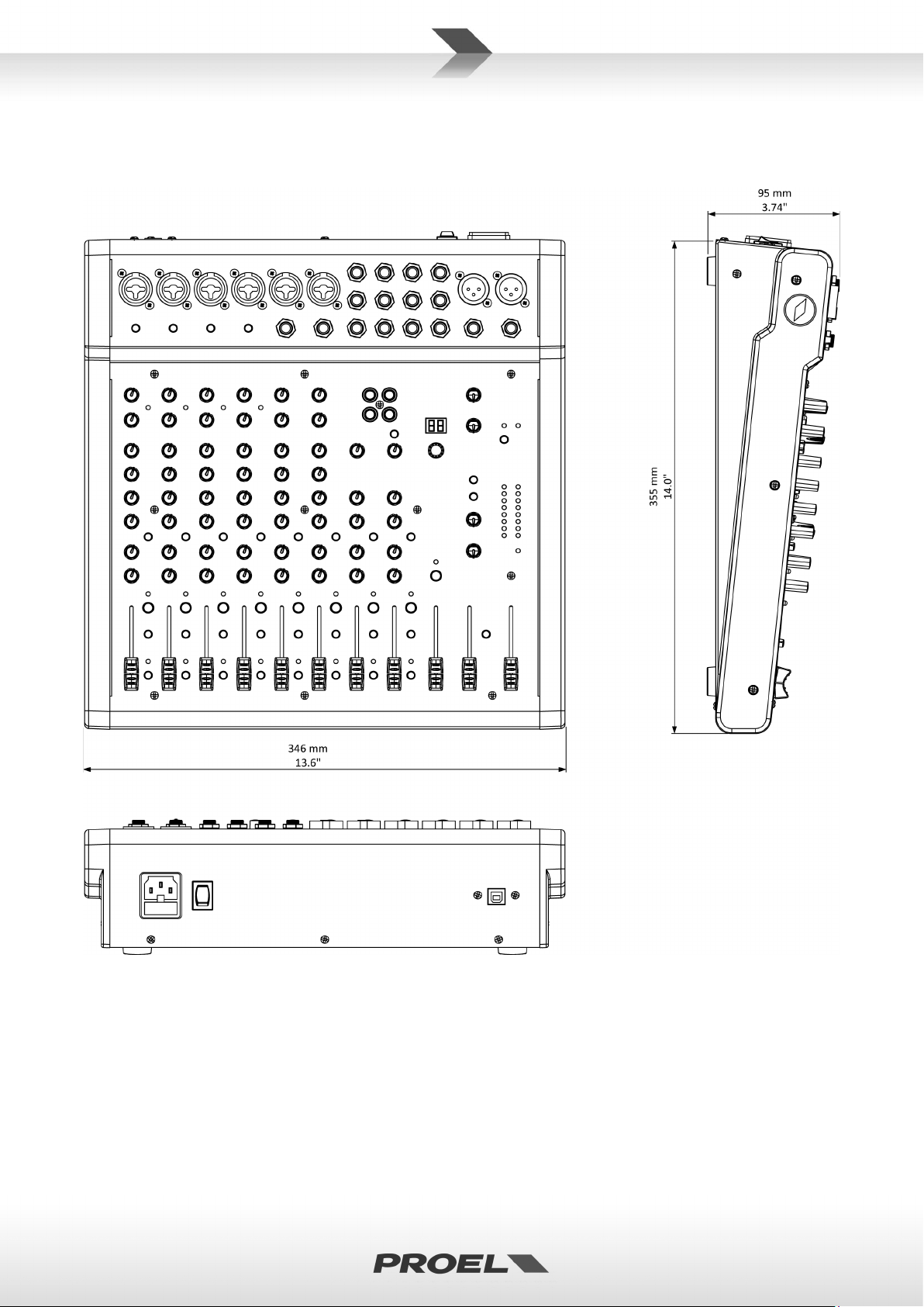
28
Mechanical Dimensions – Dimensioni Meccaniche

29
Configurations Example – Esempio Configurazioni

30
Accessories – Accessori
The available optional accessories include a padded bag (PROEL CODE BAGMQ12USB) and the rack adapters
(PROEL CODE RACKMQ12USB), its mounting instructions are show below.
Gli accessori opzionali disponibili includono una borsa di trasporto (CODICE PROEL BAGMQ12USB) e gli
adattatori a rack (CODICE PROEL RACKMQ12USB), le cui istruzioni di montaggio sono mostrate qui sotto.

31
Connectors - Connettori

32
PROEL S.p.A.
(World Headquarters - Factory)
Via alla Ruenia 37/43
64027 Sant’Omero (Te) – Italy
Tel: +39 0861 81241
Fax: +39 0861 887862
www.proel.com
 Loading...