

Page 1
P7000 H-Series User’s Manual
Page 2

READ THIS SOFTWARE LICENSE AGREEMENT BEFORE USING THIS PRINTER
Software License Agreement
CAREFULLY READ THE FOLLOWING TERMS AND
CONDITIONS BEFORE USING THIS PRINTER. USING THIS
PRINTER INDICATES YOUR ACCEPTANCE OF THESE
TERMS AND CONDITIONS. IF YOU DO NOT AGREE TO
THESE TERMS AND CONDITIONS, PROMPTLY RETURN
THE PRINTER AND ALL ACCOMPANYING HARDWARE
AND WRITTEN MATERIALS TO THE PLACE YOU
OBTAINED THEM, AND YOUR MONEY WILL BE
REFUNDED.
Definitions.
“Software” shall mean the digitally encoded, machine-readable
data and program. The term “Software Product” includes the
Software resident in the printer and its documentation. The
Software Product is licensed (not sold) to you, and Printronix,
Inc. either owns or licenses from other vendors who own, all
copyright, trade secret, patent and other proprietary rights in
the Software Product.
License.
1. Authorized Use. You agree to accept a non-exclusive
license to use the Software resident in the printer solely
for your own customary business or personal purposes.
2. Restrictions.
a. To protect the proprietary rights of Printronix, Inc.,
you agree to maintain the Software Product and
other proprietary information concerning the
typefaces in strict confidence.
b. You agree not to duplicate or copy the Software
Product.
c. You shall not sublicense, sell, lease, or otherwise
transfer all or any portion of the Software Product
separate from the printer, without the prior written
consent of Printronix, Inc.
d. You may not modify or prepare derivative works of
the Software Product.
e. You may not transmit the Software Product over a
network, by telephone, or electronically using any
means; or reverse engineer, decompile or
disassemble the Software.
f. You agree to keep confidential and use your best
efforts to prevent and protect the contents of the
Software Product from unauthorized disclosure or
use.
3. Transfer. You may transfer the Software Product with the
printer, but only if the recipient agrees to accept the
terms and conditions of this Agreement. Your license is
automatically terminated if you transfer the Software
Product and printer.
Limited Software Product Warranty
Printronix, Inc. warrants that for ninety (90) days after delivery,
the Software will perform in accordance with specifications
published by Printronix, Inc. Printronix, Inc. does not warrant
that the Software is free from all bugs, errors and omissions.
Remedy
Your exclusive remedy and the sole liability of Printronix, Inc.
in connection with the Software is replacement of defective
software with a copy of the same version and revision level.
Disclaimer of Warranties and Limitation of Remedies
1. THE PARTIES AGREE THAT ALL OTHER
WARRANTIES, EXPRESS OR IMPLIED, INCLUDING
WARRANTIES OF FITNESS FOR A PARTICULAR
PURPOSE AND MERCHANTABILITY ARE EXCLUDED.
Printronix, Inc. does not warrant that the functions
contained in the Software will meet your requirements or
that the operation of the Software will be uninterrupted or
error free. Printronix, Inc. reserves the right to make
changes and/or improvements in the Software without
notice at any time.
2. IN NO EVENT WILL PRINTRONIX, INC. BE LIABLE
FOR LOST PROFITS, LOST DATA, BUSINESS
INTERRUPTIONS, OR ANY OTHER DIRECT,
INDIRECT, INCIDENTAL OR CONSEQUENTIAL
DAMAGES ARISING OUT OF THE USE OF OR
INABILITY TO USE THIS PRODUCT, EVEN IF
PRINTRONIX, INC. HAS BEEN ADVISED OF THE
POSSIBILITY OF SUCH DAMAGES, OR ANY
DAMAGES CAUSED BY THE ABUSE OR
MANIPULATION OF THE SOFTWARE. SOME STATES
DO NOT ALLOW THE EXCLUSION OR LIMITATION OF
LIABILITY FOR CONSEQUENTIAL OR INCIDENTAL
DAMAGES, SO THE ABOVE LIMITATION MAY NOT
APPLY TO YOU.
3. Printronix, Inc. will not be liable for any loss or damage
caused by delay in furnishing a Software Product or any
other performance under this Agreement.
4. Our entire liability and your exclusive remedies for our
liability of any kind (including liability for negligence
except liability for personal injury caused solely by our
negligence) for the Software Product covered by this
Agreement and all other performance or nonperformance
by us under or related to this Agreement are limited to the
remedies specified by this Agreement.
5. California law governs this Agreement.
Termination of License Agreement
This License shall continue until terminated. This license may
be terminated by agreement between you and Printronix, Inc.
or by Printronix, Inc. If you fail to comply with the terms of this
License and such failure is not corrected within thirty (30) days
after notice. When this License is terminated, you shall return
to the place you obtained them, the printer and all copies of the
Software and documentation.
U.S. Government Restricted Rights
Use, duplication or disclosure by the Government is subject to
restrictions as set forth in the Rights in Technical Data and
Computer Software clause at FAR 242.227-7013, subdivision
(b) (3) (ii) or subparagraph (c) (1) (ii), as appropriate. Further
use, duplication or disclosure is subject to restrictions
applicable to restricted rights software as set forth in FAR
52.227-19 (c) (2).
Acknowledgement of Terms and Conditions
YOU ACKNOWLEDGE THAT YOU HAVE READ THIS
AGREEMENT, UNDERSTAND IT, AND AGREE TO BE
BOUND BY ITS TERMS AND CONDITIONS. NEITHER
PARTY SHALL BE BOUND BY ANY STATEMENT OR
REPRESENTATION NOT CONTAINED IN THIS
AGREEMENT. NO CHANGE IN THIS AGREEMENT IS
EFFECTIVE UNLESS WRITTEN AND SIGNED BY
PROPERLY AUTHORIZED REPRESENTATIVES OF EACH
PARTY. BY USING THIS PRINTER, YOU AGREE TO
ACCEPT THE TERMS AND CONDITIONS OF THIS
AGREEMENT.
Page 3

User’s Manual
P7000 H-Series Line Matrix Printers
Page 4

This document contains proprietary information protected by copyright. No
part of this document may be reproduced, copied, translated, or incorporated
in any other material in any form or by any means, whether manual, graphic,
electronic, mechanical, or otherwise, without the prior written consent of
Printronix.
Printronix makes no representations or warranties of any kind regarding this
material, including, but not limited to, implied warranties of merchantability
and fitness for a particular purpose. Printronix shall not be held responsible
for errors contained herein or any omissions from this material or for any
damages, whether direct or indirect, incidental or consequential, in connection
with the furnishing, distribution, performance, or use of this material. The
information in this manual is subject to change without notice.
COPYRIGHT 2007 PRINTRONIX, INC.
Trademark Acknowledgements
IBM, AS/400, and Proprinter are registered trademarks, and Intelligent Printer
Data Stream and IPDS are trademarks of International Business Machines
Corporation.
Printronix, PGL, LinePrinter Plus, and IGP are registered trademarks, and
P7005, P7010, P7015, P7205, P7210, P7215, P7220, and SureStak are
trademarks of Printronix, Inc.
ANSI is a registered trademark of the American National Standards Institute,
Inc.
Centronics is a registered trademark of Genicom Corporation.
CSA is a registered certification mark of the Canadian Standards Association.
Dataproducts is a registered trademark of Dataproducts Corporation.
EIA is a registered service mark of the Electronic Industries Association.
Epson is a registered trademark of Seiko Epson Corporation.
Ethernet is a trademark of Xerox Corporation.
IEEE is a registered service mark of the Institute of Electrical and Electronics
Engineers, Inc.
QMS is a registered trademark, and Code V is a trademark of Quality Micro
Systems, Inc.
TUV is a registered certification mark of TUV Rheinland of North America, Inc.
UL is a registered certification mark of Underwriters Laboratories, Inc.
ENERGY STAR is a registered trademark of the United States Environmental
Protection Agency. As an ENERGY STAR
determined that this product meets the ENERGY STAR guidelines for energy
efficiency.
®
Partner, Printronix has
Page 5

Table of Contents
1 Introduction............................................................. 9
Printer Overview .......................................................................................9
The Printer Family .............................................................................. 9
Conventions In This Manual.............................................................10
Warnings And Special Information................................................... 11
Related Documents.......................................................................... 11
Taking Care Of Your Printer............................................................. 11
Protocols And Emulations ................................................................12
2 Setting Up The Printer .......................................... 13
Before You Begin.................................................................................... 13
Power Requirements ..............................................................................13
Select A Site ...........................................................................................13
Printer Dimensions .................................................................................14
Printer Component Locations ................................................................. 17
3 Operating The Printer ........................................... 19
Powering On The Printer ........................................................................19
Operating Modes ....................................................................................19
The Control Panel...................................................................................20
Control Panel Keys ..........................................................................20
Operational Procedures..........................................................................23
Reload Paper ................................................................................... 23
Unload Paper ................................................................................... 31
Integrated Print Management System .................................................... 34
Lighter Or Darker Print .....................................................................34
Changing Ribbons............................................................................35
Cancel A Print Job ...........................................................................38
Page 6

Table of Contents
4 The Configuration Menus .....................................39
Configuration Overview ..........................................................................39
Changing And Saving Parameter Settings.......................................39
Saving Parameter Settings ..............................................................39
Default And Custom Configurations.................................................40
Navigating The Menus .....................................................................40
Changing Parameters Example ....................................................... 41
Auto Save Configuration ..................................................................44
Saving Your New Configuration .......................................................44
Optimizing Print Quality....................................................................49
Optimizing Print Speed ....................................................................49
Main Menu .............................................................................................. 50
QUICK SETUP ....................................................................................... 52
ZTP SETTINGS......................................................................................56
CONFIG. CONTROL ..............................................................................57
HOST INTERFACE ................................................................................ 59
Auto Switching Submenu .................................................................60
Centronics (Parallel) Submenu ........................................................ 62
Dataproducts Submenu ...................................................................64
Serial Submenu................................................................................ 67
IEEE 1284 Parallel (Bidirectional) Submenu.................................... 73
E-Net Adapter Submenu..................................................................74
Ethernet Submenu ........................................................................... 75
NETWORK SETUP MENU.....................................................................76
ADAPTER ADDRESS ......................................................................76
ADAPTER PARAMS ........................................................................77
ETHERNET ADDRESS ................................................................... 80
ETHERNET PARAMS...................................................................... 81
WLAN ADDRESS ............................................................................83
WLAN PARAMS............................................................................... 84
WLAN KERBEROS ..........................................................................88
WLAN LEAP..................................................................................... 90
EMULATION...........................................................................................91
Hanzi GB LP+ Emulation ................................................................. 91
Hanzi Big5 LP+ Emulation ...............................................................92
Kanji LP+ Emulation.........................................................................93
Hangul LP+ Emulation .....................................................................94
Page Format Submenu .................................................................... 98
PRINTER CONTROL .............................................................................99
ADVANCED USER...............................................................................101
DIAGNOSTICS ..................................................................................... 107
Printer MGMT .......................................................................................110
Page 7

Table of Contents
5 Interfaces............................................................ 111
Overview...............................................................................................111
Centronics Parallel Interface................................................................. 112
Centronics Parallel Interface Signals ............................................. 113
IEEE 1284 Parallel Interface................................................................. 113
Compatibility Mode......................................................................... 113
Nibble Mode ...................................................................................114
Byte Mode ......................................................................................114
Signals ...........................................................................................114
Terminating Resistor Configurations..............................................117
RS-232 And RS-422 Serial Interfaces.................................................. 119
RS-232 ...........................................................................................119
RS-422 ...........................................................................................120
Dataproducts Parallel Interface ............................................................121
Dataproducts Parallel Interface Signals .........................................122
6 Reprogramming the Security Key....................... 123
Reprogramming The Security Key........................................................ 123
How To Program The Security Key................................................ 123
7 Troubleshooting.................................................. 125
Cleaning Requirements ........................................................................125
Exterior Cleaning............................................................................125
Interior Cleaning ............................................................................. 126
Diagnosing Problems............................................................................ 128
Bar Code Verification .....................................................................128
Printing A Hex Dump...................................................................... 128
Fault Messages ..............................................................................129
A Printer Specifications ......................................... 165
Ribbon Specifications ...........................................................................165
Paper Specifications .............................................................................166
Printer Weight And Dimensions............................................................167
Environmental Characteristics..............................................................167
Electrical Characteristics ......................................................................168
Interfaces ..............................................................................................169
Printing Rates .......................................................................................170
B ASCII Character Set........................................... 171
Page 8

Table of Contents
C Zero Tear Pedestal ............................................ 173
Overview...............................................................................................173
Performance Limitations....................................................................... 173
Control Panel Menus ............................................................................175
Operation.............................................................................................. 176
Adjust The Paper Guides...............................................................176
Load Paper..................................................................................... 177
Set The Tear Bar Distance............................................................. 178
Set The Top Of Form .....................................................................179
Position The Paper Out Sensor .....................................................180
D Customer Support .............................................. 181
Printronix Customer Support Center..................................................... 181
Printronix Supplies Department............................................................181
Corporate Offices..................................................................................182
E Communication Notices ..................................... 183
Notices..................................................................................................183
Energy Star...........................................................................................185
Product Recycling And Disposal........................................................... 185
Communication Statements..................................................................186
Lithium Battery Warning ....................................................................... 190
Software License Agreement................................................................190
Page 9

1 Introduction
Printer Overview
This chapter provides a general overview of your printer and the conventions
used within this manual.
The Printer Family
The Printronix® P7000 H-Series consists of P7002H, P7202H, P7003H,
P7203H, P7006H, P7206H, P7008H, and P7208H models that are packaged
in various configurations. All of the models offer software versatility and the
latest refinements in line matrix printing technology. The print mechanisms
are housed in sound-insulated cabinets which make the printer family among
the quietest printers in the world. Additionally, your printer has a flexible
architecture that allows you to add new features and emulations as they
become available.
The printer combines the use of Flash and RAM for program execution. The
Flash is used for all program, font, and emulation storage. New fonts,
emulations, or program updates can be downloaded to Flash memory via the
parallel or serial interface, or through the PrintNet
used for buffers, print image storage, and execution variables. The Flash also
stores configuration, statistics, and internal parameters.
®
interface. The RAM is
The printer model numbers indicate printing speed and physical configuration.
Model numbers beginning with P70 indicate pedestal models. Model numbers
beginning with P72 indicate cabinet models. The final two digits in the model
number refer to the printer’s maximum speed in lines per minute (lpm): 02 for
200 lpm, 03 for 300 lpm, 06 for 600 lpm, and 08 for 800 lpm.
9
Page 10
Chapter 1 Printer Overview
Refer to the following table for a complete listing of model numbers and
options.
Table 1. The P7000 H-Series Printers
Model
Number
P7002H 200 lpm
P7202H 200 lpm
P7003H 300 lpm
P7203H 300 lpm
P7006H 600 lpm
P7206H 600 lpm
P7008H 800 lpm
P7208H 800 lpm
Print
Speed
Pedestal Cabinet
Conventions In This Manual
All uppercase print indicates control panel keys.
Example: Press the CLEAR key, then press the ON LINE key.
Quotation marks (“ ”) indicate messages on the Liquid Crystal Display (LCD).
Example: Press the ON LINE key. “OFFLINE” appears on the LCD.
The + (plus) symbol represents key combinations.
Example: “Press
> (DOWN) key at the same time.
= + >” means press the = (UP) key and the
10
Page 11

Warnings And Special Information
Warnings And Special Information
Read and comply with all information highlighted under special headings:
WARNING
CAUTION
A warning notice calls attention to a condition that could harm you.
WARNUNG
Ein Warhinweis dieser Art weist auf Verletzungsgefahr hin.
AVISO
Las notas de adviso llaman la atención sobre una condición que puede
causar lesiones.
ATTENTION
Attire votre attention sur une opération pouvant présenter un danger.
AVVERTENZA
Un’indicazione di avvertenza segnala una condizione di pericolo
suscttibile causare lesioni all’operatore.
A caution notice calls attention to a condition that could damage the
printer.
Related Documents
•
Maintenance Manual —
matrix printer at the field service level of maintenance.
Explains how to maintain and repair the line
•
Network Interface Card User's Manual —
protocols, configuration, and operation.
Information about network
• LQ-1600K Emulation For The P7000 H-Series Of Line Matrix Printers
Programmer’s Reference Manual — Covers the host control codes for the
LQ-1600K emulation.
• KS Programmer’s Reference Manual — Covers the host control codes for
the KS emulation.
• KSSM Programmer’s Reference Manual — Covers the host control codes
for the KSSM emulation.
Taking Care Of Your Printer
Your printer will produce high print quality jobs if it is well taken care of.
Periodic cleaning, handling the printer properly, and using the correct printer
supplies such as paper and ribbons ensures optimum performance. Chapter
7 explains how to clean the printer, and printer supplies are listed in
Appendix A.
11
Page 12

Chapter 1 Printer Overview
Protocols And Emulations
A
protocol
printer and its host computer. These rules consist of codes that manipulate
and print data and allow for machine-to-machine communication. A printer
and its host computer must use the same protocol. As used in this manual,
protocol and emulation mean the same thing.
Most impact printers use single ASCII character codes to print text, numbers,
and punctuation marks. Some characters, are defined as control codes.
Control codes instruct the printer to perform specific functions, such as
underlining text, printing subscripts, setting page margins, etc. The main
difference between most printer protocols is in the characters used to create
control codes and the ways in which these characters are formatted.
When the printer executes the character and control codes of a particular
printer protocol, it is “emulating” that printer.
is a set of rules governing the exchange of information between the
12
Page 13

2 Setting Up The Printer
Before You Begin
Read this chapter carefully before installing and operating the printer. The
printer is easy to install. However, for your safety and to protect valuable
equipment, perform all the procedures in this chapter in the order presented.
Power Requirements
The printer must be connected to a power outlet that supplies 88 to 135 Volts
AC or 178 to 271 Volts AC at 50 to 60 Hz. The printer automatically senses
and adjusts itself to conform to the correct voltage range.
Primary circuit protection is provided by the power switch, which is also a
circuit breaker. Consult an electrician if printer operation affects local
electrical lines. See “Electrical Characteristics” on page 168 for additional
power specifications.
IMPORTANT
Select A Site
Printer power should be supplied from a separate AC circuit protected
at 10 amperes for 100 - 120 volts or 5 amperes for 200 - 240 volts at 50 or
60 Hertz.
Select a printer site that meets all of the following requirements:
• Permits complete opening of the printer cover and doors.
• For cabinet models, allows at least three feet of clearance behind the
printer. (This permits air to circulate freely around the printer and provides
access to the paper stacking area.)
• Has a standard power outlet that supplies 88-135 Volts AC or
178-270 Volts AC power, at 47 to 63 Hz.
• Is relatively dust-free.
• Has a temperature range of 10° C to 40° C (50° F to 104° F) and a
relative humidity from 15% to 90% non-condensing.
• Is located within the maximum allowable cable length to the host
computer. This distance depends on the type of interface you plan to use,
as shown in Table 2 on page 14.
13
Page 14
Chapter 2 Printer Dimensions
Table 2. Maximum Interface Connection Cable Length
Interface Type Maximum Cable Length
Centronics Parallel 5 meters (15 feet)
Dataproducts Parallel 12 meters (40 feet)
IEEE 1284 Parallel 10 meters (32 feet)
Serial RS-232 15 meters (50 feet)
Serial RS-422 1220 meters (4000 feet)
Dataproducts Long Line 150 meters (492 feet)
Coax 1500 meters (4920 feet)
Twinax 1500 meters (4920 feet)
Twinax (shielded cable) 1500 meters (4920 feet)
Twisted Pair / Type 3 300 meters (985 feet)
Ethernet 10/100Base-T 100 meters (328 feet)
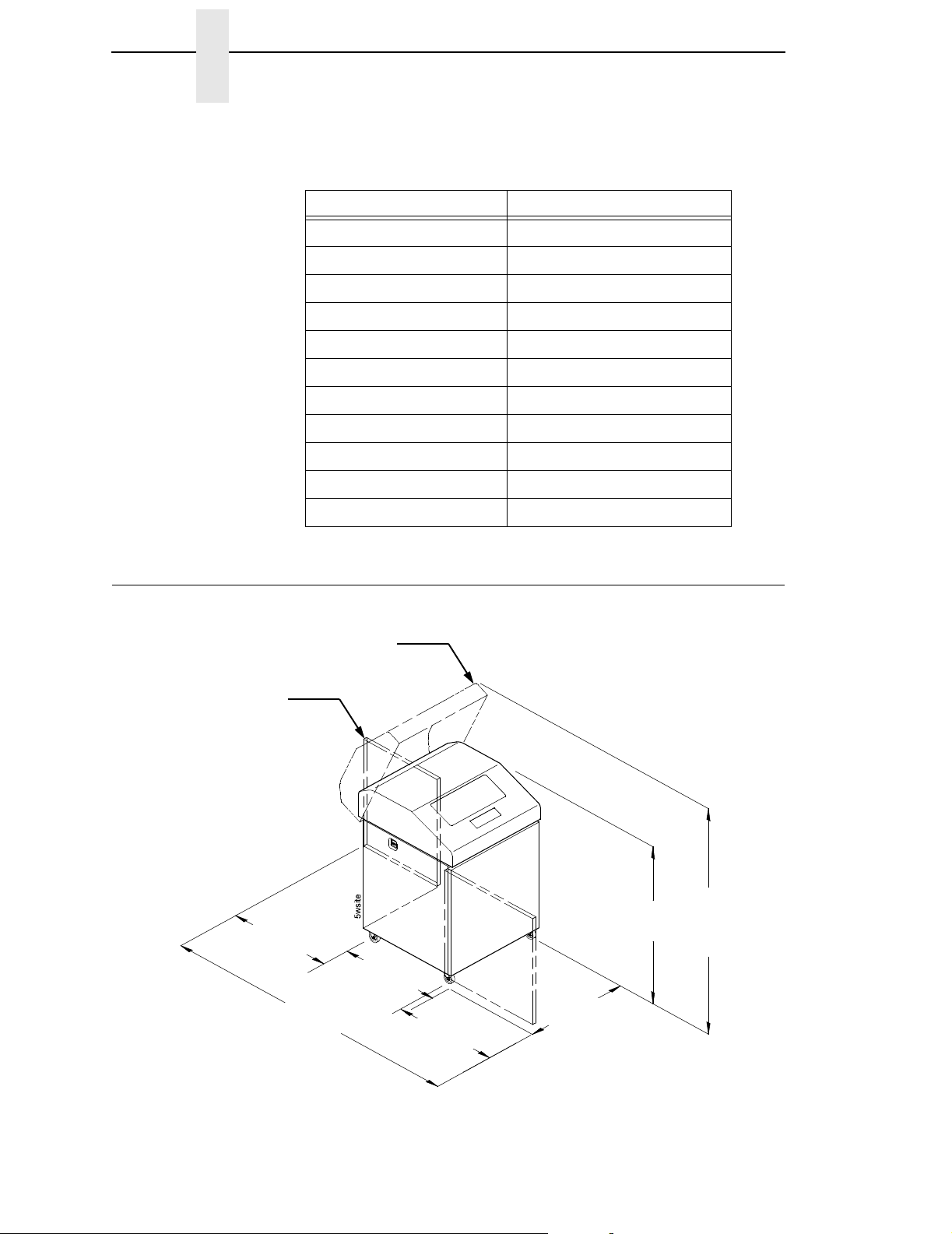
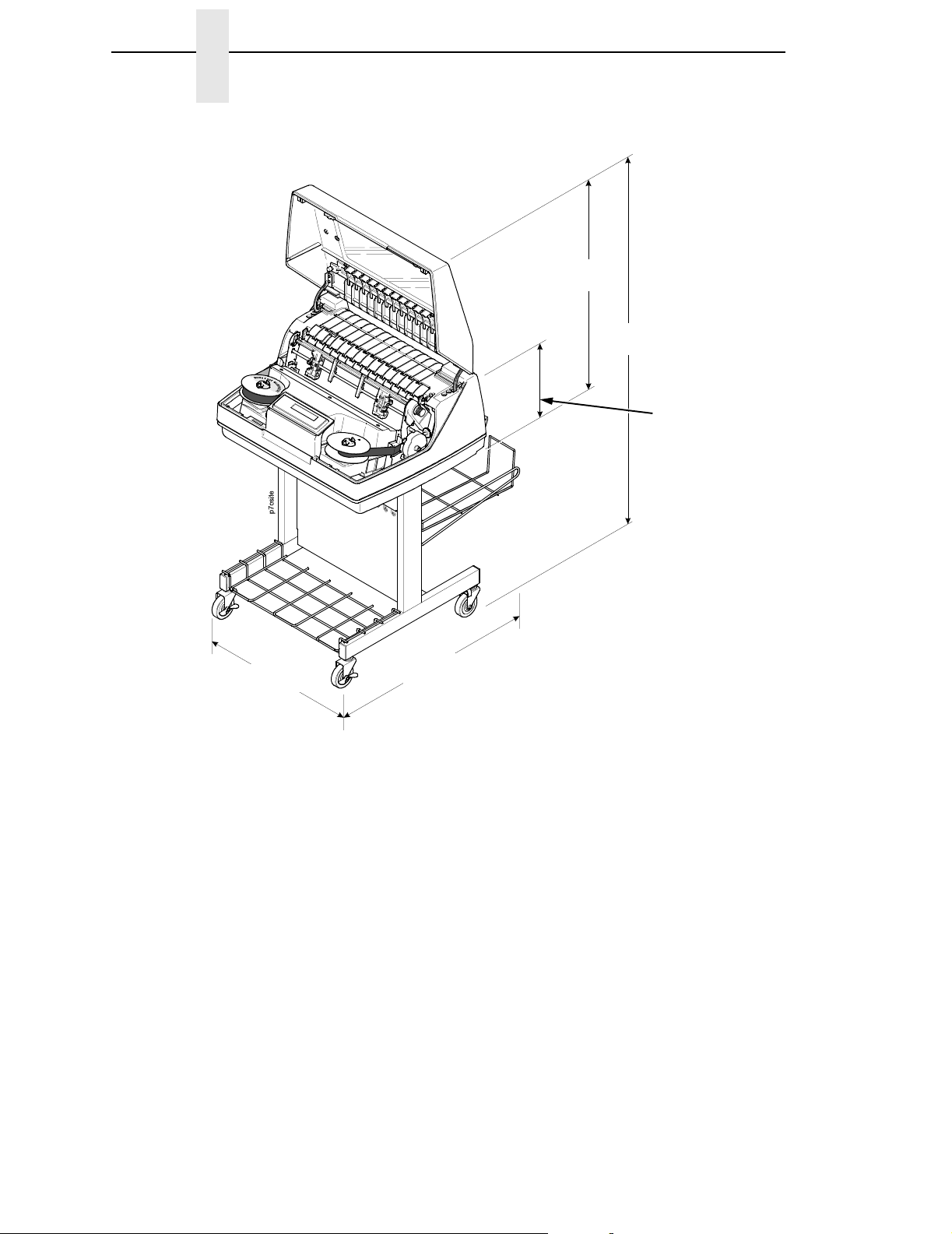
Printer Dimensions
Printer Cover
Cabinet Rear Door
27.0 in
(68.84 cm)
83.0 in
(210.8 cm)
29.0 in
(73.7 cm)
27.0 in
(68.6 cm)
27.0 in
(68.6 cm)
57.5 in
(146.1 cm)
41.0 in
(104 cm)
14
Figure 1. Printer Dimensions - Cabinet Model
Page 15
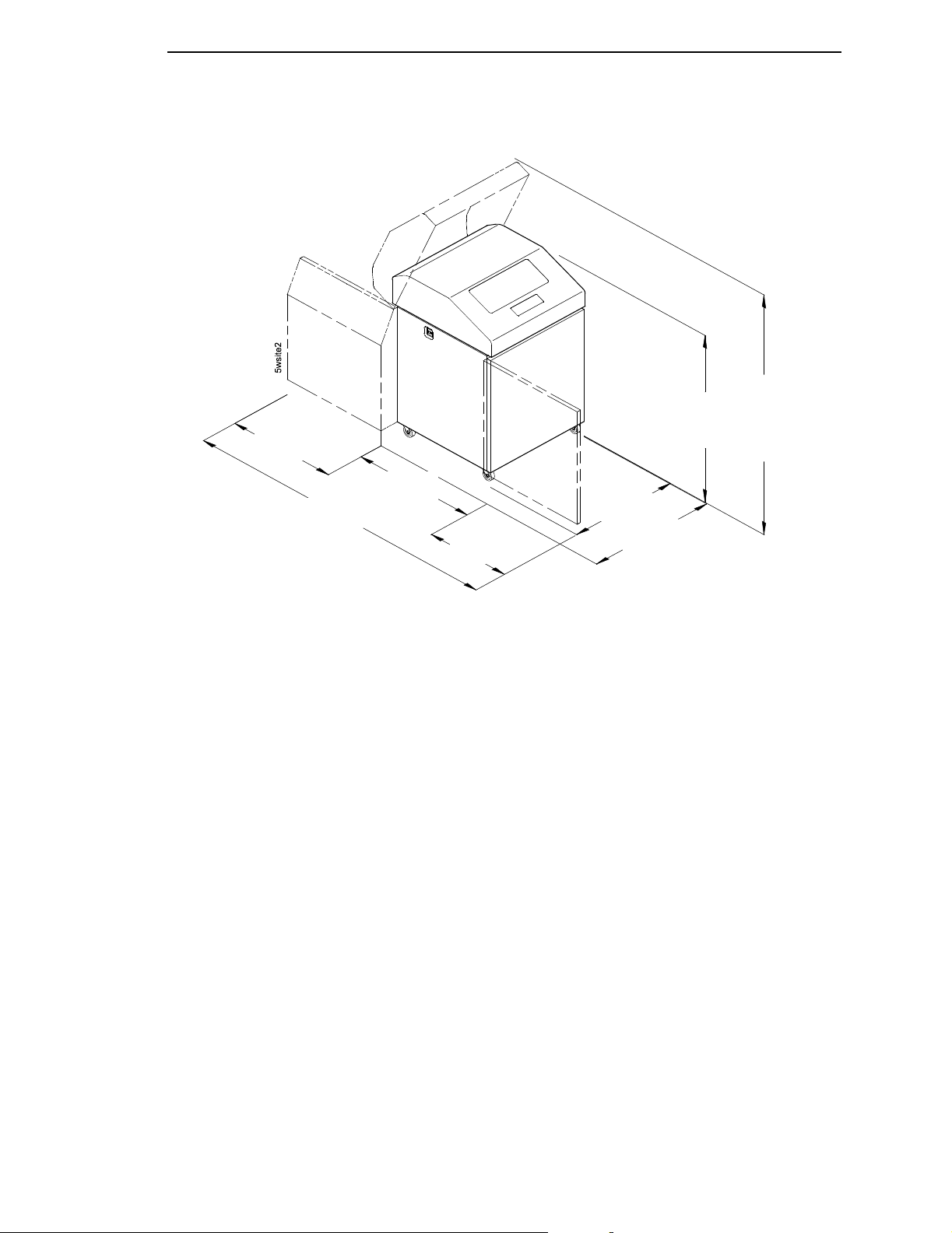
42.5 in
27.0 in
(68.6 cm)
(210.8 cm)
83.0 in
32.5 in
(82.6 cm)
27.0 in
(68.6 cm)
27.0 in
(68.6 cm)
(107.8 cm)
32.0 in
(81.3 cm)
Figure 2. Printer Dimensions - Cabinet Model with Paper Stacker
59.0 in
(149.9 cm)
15
Page 16
Chapter 2 Printer Dimensions
25 in.
(63.5 cm)
48.0 in.
(122 cm)
10.5 in.
(26.67 cm.)
24.6 in.
(62.48 cm)
30 in.
(76.2 cm.)
Figure 3. Printer Dimensions - Pedestal Model
16
Page 17
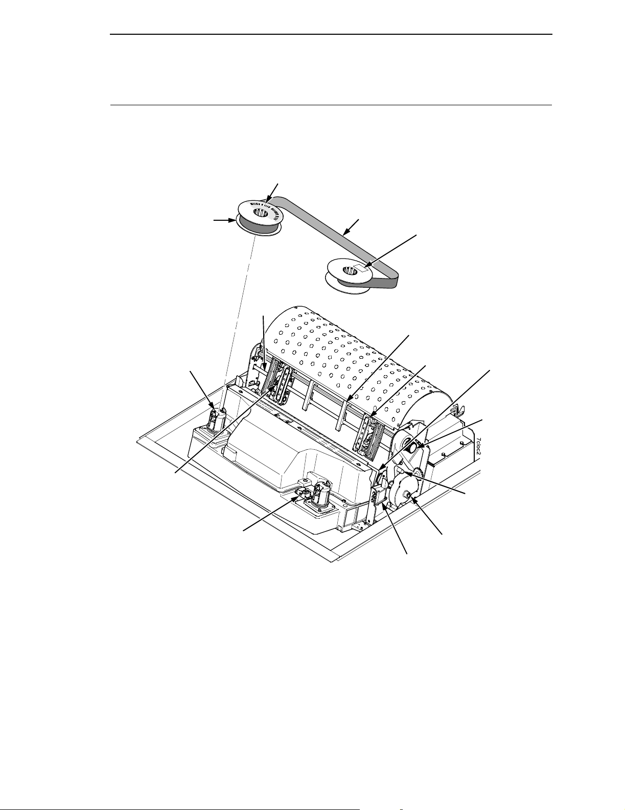
Printer Component Locations
Familiarize yourself with the names and locations of the printer components,
shown in Figure 4 before continuing with the rest of the installation
procedures.
Barcode
Ribbon Spool
Ribbon Hub
Blue Tractor
Lock (2)
Splined
Shaft
Ribbon
Date Code Label
Paper Support
Tractor (2)
Hammer Bank
Cover and
Ribbon Mask
Vertical
Position Knob
Platen Lever
Barcode Sensor
Figure 4. Printer Component Locations
Platen Stop
Ribbon Guide (2)
17
Page 18

Chapter 2 Printer Component Locations
18
Page 19

3 Operating The Printer
Powering On The Printer
When you power on the printer, it executes a self-test. The default power-up
state is online. When the self-test completes and the software has initialized
successfully, the status indicator light turns on, indicating the printer is online.
The default value of the type of emulation you have installed appears in the
upper right corner of the display. The ribbon life remaining is shown on the
second line.
If there is a fault during the self-test, the status indicator flashes and a specific
fault message appears on the display (such as “LOAD PAPER”). The alarm
also sounds if it is configured to do so. See “ LCD Message Troubleshooting
Table” on page 130 for information on fault messages and solutions.
Operating Modes
Online. In online mode, the printer can receive and print data sent from the
host. Pressing the ON LINE key toggles the printer from online to offline
mode. The status indicator is lit in online mode.
Offline. In offline mode, you can perform operator functions, such as loading
paper and setting top-of-form. You can also move within the printer
configuration menus. Pressing the ON LINE key toggles the printer from
offline to online mode. The status indicator is off in offline mode.
Fault. In fault mode, a condition exists which must be cleared before printing
can continue. The status indicator flashes, the alarm beeps (if configured to
sound), and a descriptive fault message displays.
The current operating mode can be selected via control panel keys or can
result from routine operations such as powering on the printer.
19
Page 20
Chapter 3 The Control Panel
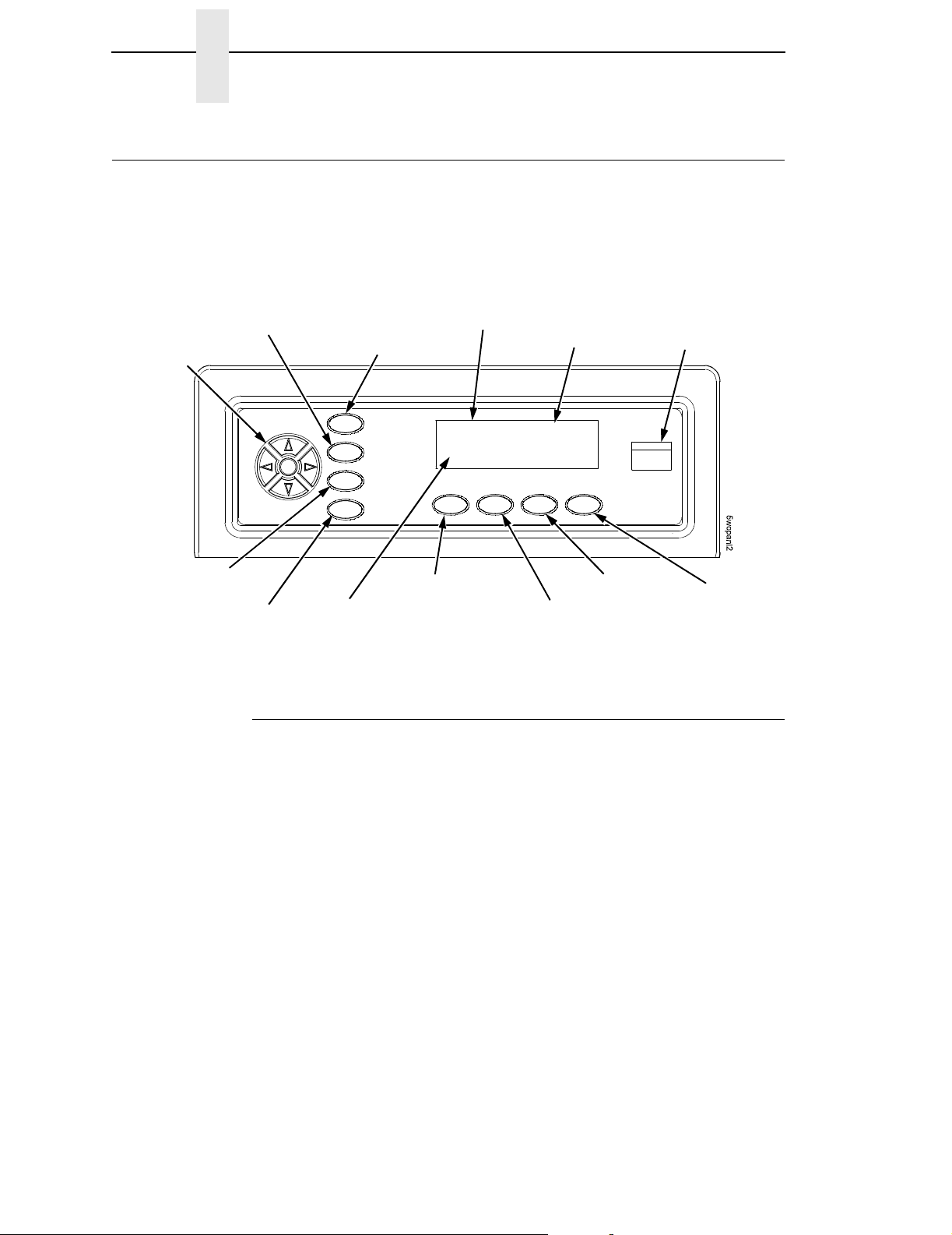
The Control Panel
Figure 5 shows the keys, displays, and indicators as they appear on the
control panel. The following section provides the descriptions, and functions
of the control panel keys.
Circular
PRT CONFIG
Pad
JOB SELECT
Key combinations are indicated with the plus (+) sign. For example, “Press
+
>” means to press the = key and the > key at the same time.
Message Display
ENTER
SET TOF
ON LINE/CLEAR
Ribbon Life
Indicator
Figure 5. Control Panel
Emulation
ONLINE <LP+>
RIBBON LIFE 100%
VIEW/EJECT
PAPER ADVANCE
Status Indicator
CANCEL
=
Control Panel Keys
ON LINE / CLEAR
Toggles the printer between online and offline modes. If a fault condition
exists, pressing this key will clear the fault message and return the printer
from fault mode to offline mode.
NOTE: If the fault condition is not corrected
message will reappear when attempting to place the printer online.
PAPER ADVANCE
Performs advance to top-of-form, as defined by the current active form length.
The key works both online and offline.
• If online with data in the printer buffer, the data will print and then the
paper will move to the next top-of-form.
• In the fault state, PAPER ADVANCE will advance the paper. The first
press moves to the top of the next available form. All subsequent presses
advances one forms length as defined by the current active forms length.
before
pressing this key, the fault
20
Page 21

Control Panel Keys
VIEW / EJECT
When the printer is online or offline, pressing this key executes the view or
eject function, depending on whether the printer is a cabinet or a pedestal (or
zero tear pedestal).
If online with data in the printer buffer, the data prints and the key functions as
described below.
If in a fault state, this key will be ignored.
• View Function — for cabinet models, pressing the
VIEW/EJECT key moves the last data printed to the tractor area for
viewing. While in the view state, the message "Printer in View" displays,
pressing the UP or DOWN arrow keys moves the paper up or down in 1/
72 inch increments. This is done to align the image within a pre-printed
form, for example. Refer to the UP and DOWN key functions for additional
details on the microstep feature. Pressing VIEW/EJECT a second time
moves the paper back to the adjusted print position.
Eject Function — for pedestal models, when the VIEW/EJECT key is
pressed, the bottom of the last printed form will move to the tear bar position.
The message "READY TO TEAR/EJECT To Return" displays. While in this
position, pressing the UP or DOWN arrow keys moves the paper up or down
in 1/72 inch increments. Refer to the Up and Down key functions for additional
details on the microstep feature. When the VIEW/EJECT key is pressed a
second time, the printer will move the paper to enable printing on the next
available form.
CANCEL
In offline mode, this key cancels all data in the print buffer, if enabled in
“ADVANCED USER” menu (see page 101). The print buffer is cleared without
printing any of the data and the current paper position is set as the top-of-
form. If this function is disabled, the CANCEL key will be ignored.
NOTE: Use of this key will cause loss of data
.
SET TOF
Sets the top-of-form on the printer. This key is active only when the printer is
offline and will not operate if the printer is in a fault condition. The paper
moves down to the print position and aligns to the top-of-form. See the
Setup Guide
NOTE: If there is any data in the buffer, the paper will move to the last print
for the complete top-of-form setting procedure.
position.
Quick
PRT CONFIG
In offline mode, PRT CONFIG prints the current printer configuration. This key
requires a confirmation with the ENTER key; pressing any other key will exit
from this function. See “The Configuration Menus” on page 39 for an
explanation of configuration menus.
21
Page 22

Chapter 3 The Control Panel
JOB SELECT
In offline mode, this key allows for fast selection of any of the previously
stored configurations. Pressing this key causes the printer to cycle through
the following messages: Load Config., Factory Config, Load Config 1, Load
Config 2, Load Config 3,...,Load Config 8.
ENTER
When navigating the configuration menus, ENTER selects the currently
displayed option value as the active value. An asterisk (*) appears next to the
active value on the display. ENTER is also used for starting and stopping
printer tests and generating a configuration printout.
NOTE: The ENTER key must be unlocked in order to function.
See UP + DOWN, below.
The ENTER key lock and unlock function can be configured to be a
key combination other than
UP or DOWN ( = or > )
= + > (see page 105).
Moves up or down between levels in the configuration menus and makes
vertical forms adjustment. After pressing VIEW, press
paper up or down in 1/72 inch increments for fine vertical forms alignment.
When the printer is in offline mode, press
configuration menus.
= or > to move through levels in the
= or > to adjust the
UP + DOWN ( = + > )
Locks and unlocks the ENTER key.
NOTE: The ENTER key lock and unlock function can be configured to be a
key combination other than
= + > (see page 105).
PREV or NEXT ( ; or < )
Moves between the options on the current level of configuration menu. In the
configuration menu, press
through the menu selections on the same level.
; to scroll backward or press < to scroll forward
PREV + NEXT ( ; + < )
When both keys are pressed simultaneously, the printer will reset to the
power-up configuration and reset its internal state (in offline mode).
Ribbon Life Indicator
22
The second line of the LCD displays the remaining life of the currently
installed ribbon. The default settings for this feature should match the
requirements for most applications; no special user setup is needed. If your
particular application requires darker printing or can tolerate lighter printing,
the ribbon end point can be adjusted as appropriate. Please refer “Ribbon
End Point” on page 99.
Page 23
Operational Procedures
This section contains routine printer operating procedures on how to:
• reload paper;
• unload paper;
• cancel a print job.
Reload Paper
Do this procedure when “LOAD PAPER” displays. (This message occurs
when the last sheet of paper passes through the paper slot.) This procedure
reloads paper without removing the last sheet of the old paper supply, while
retaining the current top-of-form setting.
Reload Paper
Cabinet Models
1. Raise the printer cover. Raise the platen lever as far as it will go. (See
“Printer Component Locations” on page 17 for the location of the lever.)
2. Press ONLINE/CLEAR to turn off the alarm. Do not open the tractor doors
or remove the existing paper.
3. For cabinet models, open the front door. Align the paper supply with the
label on the floor. Ensure the paper pulls freely from the box.
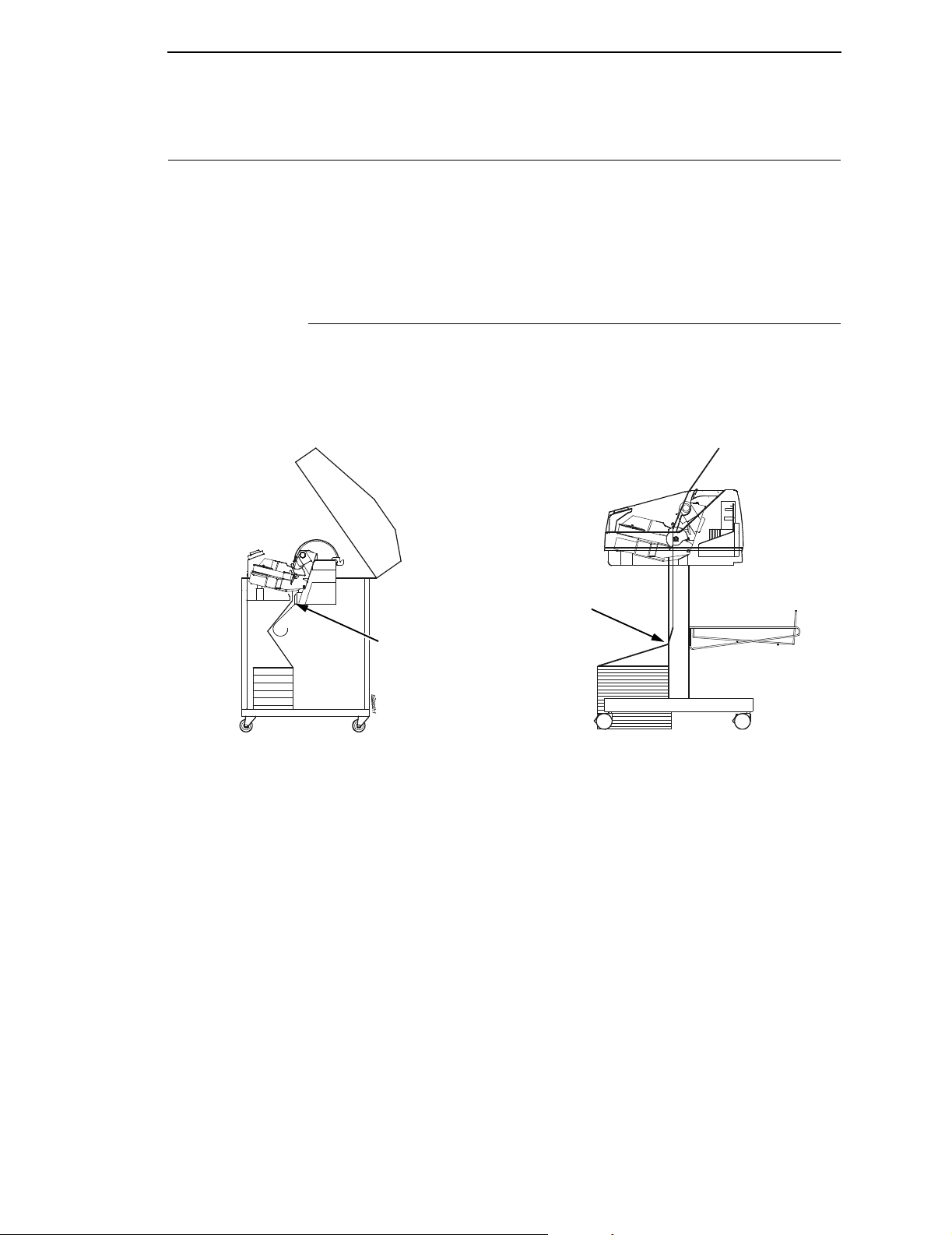
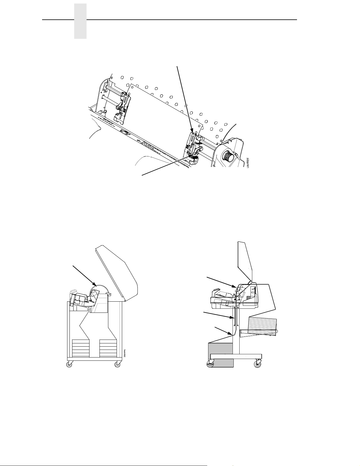
4. Feed the paper up through the paper slot (see Figure 6). It may be easier
to feed one corner of the new paper up through the slot first. When this
corner can be grasped from the top, rotate the paper back to the normal
position.
NOTE: If you are using thick, multi-part forms and are unable to load the new
Paper Slot
Paper Slot
p7clod1
Pedestal Models
Figure 6. Paper Slot Location
paper over the existing paper, go to step 15.
5. Hold the paper to prevent it from slipping down and through the paper
slot.
23
Page 24
Chapter 3 Operational Procedures
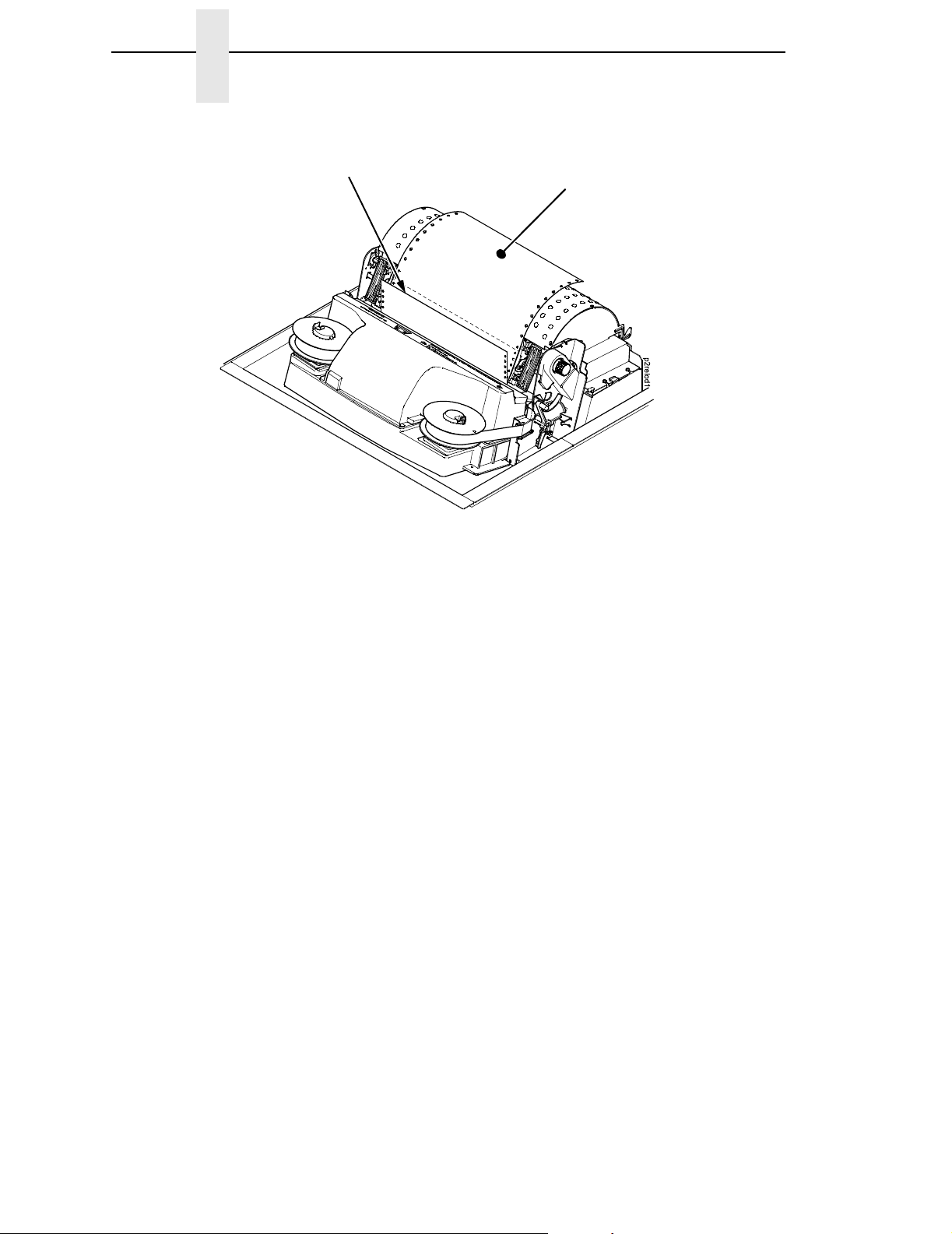
New Paper
Figure 7. Loading New Paper into the Printer
6. Pull the new paper above and behind the ribbon mask, but in front of the
existing paper. The ribbon mask location is shown on the ribbon path
diagram. If necessary, gently press the existing paper back.
Existing Paper
7. Align the top edge of the new paper with the top perforation of the existing
paper.
8. Load the new paper over the existing paper. Open and load the tractors
one at a time to prevent the paper from slipping.
NOTE: Make sure that the top edge of the new paper lines up with the top
horizontal perforation of the last page.
24
Page 25
Reload Paper
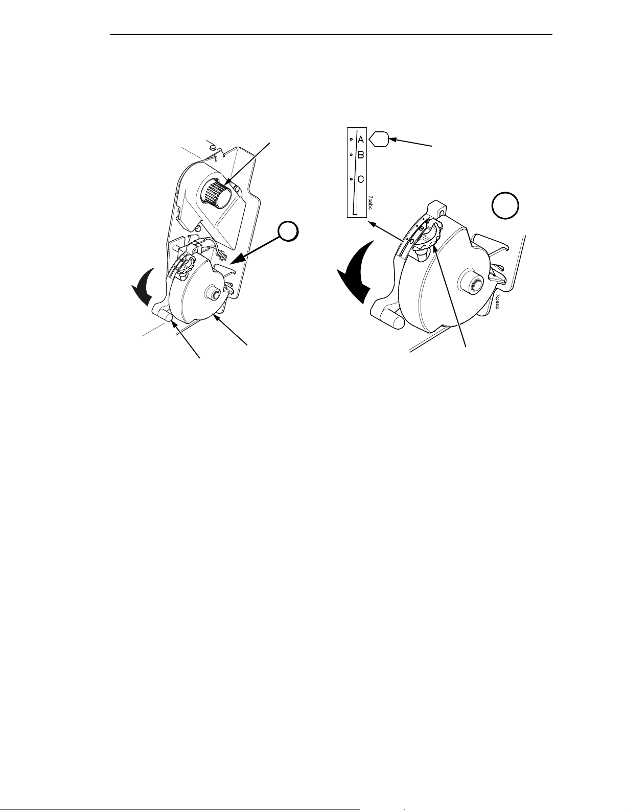
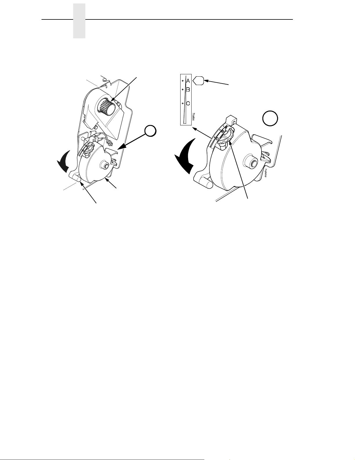
Vertical Position Knob
7crib opn
Paper Thickness
Indicator
A
Platen Stop
Platen Lever
Figure 8. Setting the Platen Lever
9. Turn the platen stop knob clockwise or counterclockwise to match the
paper thickness. (The A-B-C scale corresponds approximately to 1-, 3-,
and 6-part paper thickness).
Platen Stop
Knob
A
NOTE: If you are using the same thickness of paper, there is no need to
readjust.
10. Lower the platen lever.
NOTE: Do not set the platen lever too tightly; excessive friction can cause
paper jams, ribbon jams with potential for ribbon damage, smeared
ink, or wavy print.
11. Press ONLINE/CLEAR to remove the “LOAD PAPER” fault message
from the display.
12. Press PAPER ADVANCE several times to make sure the paper feeds
properly beyond the tractors and over the lower paper guide. Feed
sufficient paper to ensure the paper stacks correctly.
13. Close the printer cover. Close the cabinet front door.
14. Press ON LINE/CLEAR
printing.
to place the printer in online mode and resume
25
Page 26
Chapter 3 Operational Procedures
Paper Slot
Paper Slot
p7clod1
Cabinet Models
NOTE: Perform steps 15 through 32 only if you are unable to load the new
15. Open both tractor doors.
16. Remove the old paper from the tractors. Allow the paper to fall into the
17. Feed the new paper up through the paper slot. Hold the paper to prevent
Pedestal Models
Figure 9. Paper Slots on the Printers
paper over the existing paper.
paper supply area.
it from slipping down through the paper slot.
Tractor Door
Paper
26
Figure 10. Loading Paper on the Left Tractor
Page 27
Reload Paper
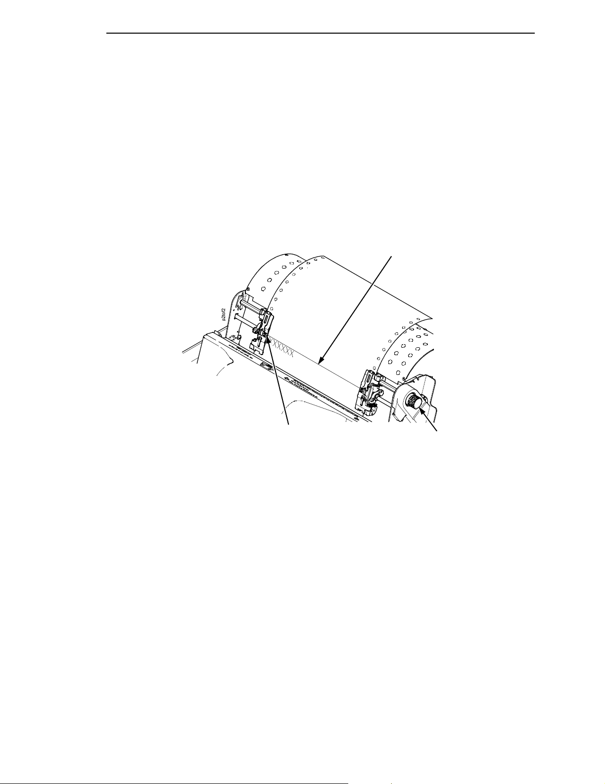
18. Pull the paper above and behind the ribbon mask. See Figure 4 on
page 17 for the ribbon mask location.
19. Load the paper on the left tractor.
20. Close the tractor door.
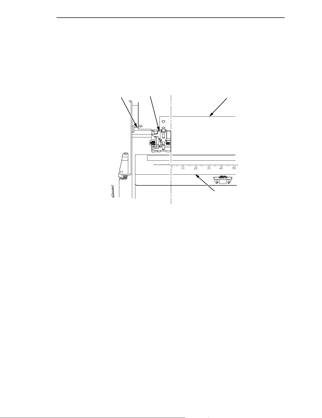
Tractor Splined
Shaft
Tractor
Paper
CAUTION
Scale
Figure 11. Positioning the Left Tractor to Avoid Damage
To avoid damage to the printer caused by printing on the platen, always
position the left tractor unit directly to the left of the “1” mark on the
paper scale.
21. Normally, you should not need to adjust the position of the left tractor. If
adjustment is necessary, unlock the left tractor. Slide the tractor until it is
directly to the left of the number “1” on the paper scale and lock it. (You
can also use the paper scale to count columns.)
27
Page 28
Chapter 3 Operational Procedures
Tractor Lock
Tractor Door
Upper Paper
Upper Paper
Guide
Guide
Figure 12. Loading Paper onto the Sprockets
22. Unlock the right tractor.
23. Load the paper onto the sprockets and close the tractor door.
If necessary, slide the right tractor to remove paper slack or to adjust for
various paper widths. Then, lock the tractor.
Upper Paper
Guide
Wire Guide (2)
Paper Slot
p7clod2
28
Cabinet Model Pedestal Model
Figure 13. Using the Paper Guide to Orient the Paper
Page 29
Reload Paper
24. Pedestal models:
Using the vertical position knob to move the paper up, guide the paper
over the lower paper guide and through the slot in the top cover. For
pedestal models with the Quick Access Cover, refer to the
Guide
for paper exiting options.
Quick Setup
25. Press PAPER ADVANCE several times to make sure the paper feeds
properly beyond the tractors and over the lower paper guide. Feed
sufficient paper to ensure the paper stacks correctly.
26. Cabinet models:
Open the cabinet rear door. Make sure the paper is aligned with the label
in the output area (inside the cabinet). Close the front and rear doors.
Perforation
TOF Indicator
Vertical Position Knob
Figure 14. Aligning the Perforation with the TOF Indicator
27. Align the top of the first print line with the TOF indicator on the tractor by
rotating the vertical position knob. For best print quality, set the top-ofform at least 1/2 inch below the perforation.
NOTE: For exact positioning, press the VIEW/EJECT key to move the last
data printed to the tractor area for viewing. While in View mode
“Printer in View” displays. Press the Up or Down Arrow keys to move
the paper vertically in small increments. Pressing the VIEW/EJECT
key a second time moves the paper back to the adjusted print
position. The key owrks both online and offline provided that the
printer is in View mode. (This procedure is applicable for both the
cabinet and pedestal models.)
29
Page 30
Chapter 3 Operational Procedures
Vertical Position Knob
7cribopn
A
Paper Thickness
Indicator
A
Platen Stop
Platen Stop
Platen Lever
Figure 15. Adjusting the Platen Lever
28. Lower the platen lever. Set it to match the paper thickness. (The A-B-C
scale corresponds approximately to 1-, 3-, and 6-part paper thickness.
Adjust until you have the desired print quality.)
29. Lower the platen lever to set it to the paper thickness indicated by the
auto platen stop.
30. Press ONLINE/CLEAR to clear any fault messages (such as “LOAD
PAPER”) from the LCD.
31. Press SET TOF. The top-of-form you have set moves down to the print
position. If there is data in the buffer, the paper moves forward to the last
print position on the next page.
32. Press ONLINE/CLEAR and close the printer cover.
Knob
30
Page 31

Unload Paper
Unload Paper
1. Press ON LINE to place the printer in offline mode and open the printer
cover.
2. For cabinet models, open the cabinet rear door. For models with the
power stacker installed, press the STACKER UP key on the rear control
panel.
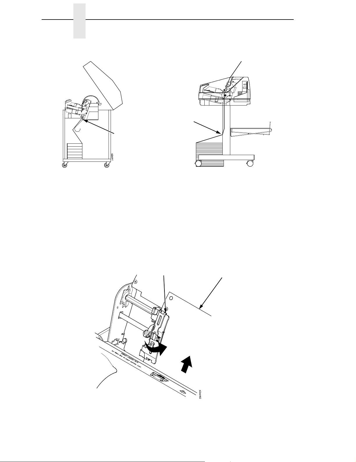
Paper
Perforation
Figure 16. Unloading the Paper from the Printer
3. Tear off the paper at the perforation.
4. Allow the paper to fall to the back of the printer and into the paper
stacking area.
5. For pedestal models, remove the stacked paper from the paper tray.
31
Page 32

Chapter 3 Operational Procedures
Paper
5sndrwop
Power Stacker
Figure 17. Removing Stacked Paper from the Printer
6. For cabinet models, remove the stacked paper from the rear cabinet floor.
For cabinet models with the power stacker installed, remove the paper
from the wire paper tent and press the STACKER DOWN key to lower the
stacker mechanism.
7. Close the cabinet rear door.
32
Page 33
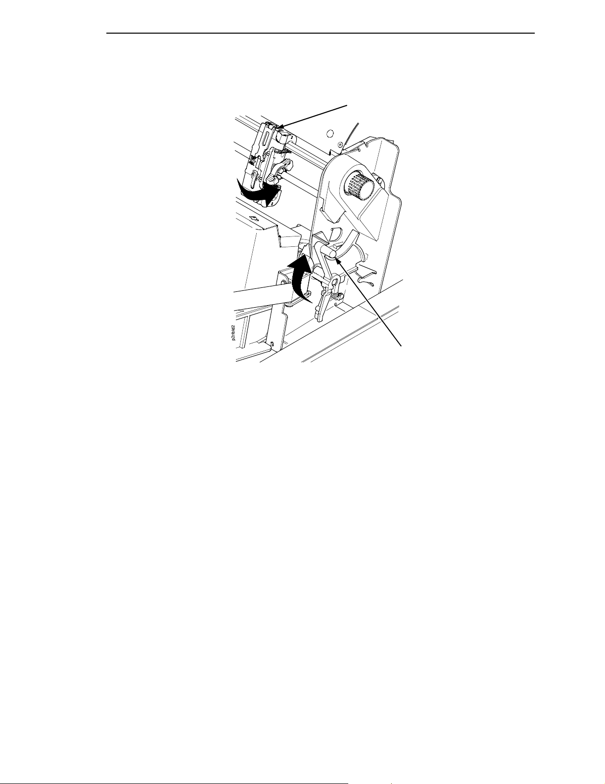
Tractor Door
Unload Paper
CAUTION
Platen Lever
Figure 18. Completely Removing the Paper
8. To completely remove the paper from the printer:
a. Raise the platen lever as far as it will go and open both tractor doors.
Be careful when pulling any paper backward through the paper path,
especially when using a label stock. If you are not careful, labels can
detach and adhere to the printer within the paper path, where only an
authorized service representative can remove them.
b. Open the cabinet front door.
c. Gently pull the paper down through the paper slot. Allow the paper to
fall into the paper supply area.
d. Remove the paper from the paper supply area.
33
Page 34

Chapter 3 Integrated Print Management System
Integrated Print Management System
The P7000’s Integrated Print Management System feature automatically
monitors and communicates the status of the ribbon’s life to help the operator
know when to change ribbons. Using a special bar coded spool, the P7000
automatically detects when a new or used ribbon is installed and determines
the ribbon’s length, ink color, and expected yield. The ribbon life, starting from
100% when new and decreasing to 0% when depleted, is always displayed
on the control panel. See Figure 5 on page 20.
When the ribbon life reaches 2%, a warning message “RIBBON UNDER 2%/
Change RBN soon” appears on the control panel display. The control panel
status indicator lamp flashes. The printer will continue printing in this condition
until the ribbon life reaches 0% at which time, printing will stop. The ribbon
may be changed at any time while the printer is in the “RBN END POINT/
Change Ribbon” condition without losing data in the printer’s buffer. Simply
follow the procedures outlined below to change the ribbon.
You may also resume printing for approximately two more minutes without
changing the ribbon by pressing the ONLINE/CLEAR key twice. This may be
done as many times as needed to complete the job in progress.
Lighter Or Darker Print
The ribbon life value as determined by the Integrated Print Management
System is factory set so that the image quality at the end of the ribbon life is
as good as it was when the ribbon was new. You may adjust the ribbon end
point for a lighter or darker image as required for your printing needs. See
“PRINTER CONTROL” on page 99..
34
Page 35

Changing Ribbons
Changing Ribbons
Before changing the ribbon, determine whether at the end of ribbon life if you
want to make the print lighter (extend the ribbon life) or darker (shorten the
ribbon life). If you want to make the print lighter, go to “Ribbon End Point” on
page 55 and follow the procedures for adjusting the image density. If you are
satisfied with the print darkness, or if you want to increase the darkness at the
end of ribbon life, continue with the following steps.
Blue Tractor
Door (2)
Figure 19. Preparing to Load the Ribbon
1. Open the printer cover.
2. Raise the platen lever as far as it will go.
3. Close the tractor doors.
4. Remove the old ribbon and discard properly.
Platen Lever
35
Page 36

Chapter 3 Integrated Print Management System
Date Code Label
Spool
Right Hub
IMPORTANT
Figure 20. Loading the Barcoded Ribbon
5. Place the empty spool on the right hand side ribbon hub and press it into
place.
The empty spool has a barcode label on the bottom side and a date code
label on the top. Once the sensor reads and logs the ribbon barcode, the
Integrated Print Management System starts to track ribbon usage.
A date code label is on the top side of the right hand spool.
If you remove the ribbon during the course of its life and want to
re-install the same ribbon, be sure to place the same spools on the
correct hubs.
36
Page 37

Ribbon Spool
Left Hub
Changing Ribbons
A
Ribbon Loading
Instructions For
Future Reference
Figure 21. Threading the Ribbon Around the Ribbon Guide
6. Thread the ribbon around the ribbon guide and along the ribbon path.
7. Place the full spool on the left hub.
8. Press the spool down until it snaps into place.
Hammer
Bank Cover
Ribbon Mask
A
Ribbon Guide
(Both Sides)
Be sure to thread the ribbon between the hammer bank cover and the
ribbon mask.
9. Turn the right spool by hand to make sure the ribbon tracks correctly in
the ribbon path and around the ribbon guides.
NOTE: If there are ink stained fingerprints on the ribbon barcode (located on
the ribbon spool), wipe it clean with a soft cloth or towelette
moistened with alcohol.
10. Close the platen lever.
11. Close the printer top cover.
If you want to increase the darkness level of the ribbon at the end of life, go to
“Ribbon End Point” on page 55 and follow the procedures for adjusting the
image density.
If you are satisfied with the print darkness, press the
ONLINE/CLEAR key twice to return the printer to operation.
37
Page 38

Chapter 3 Integrated Print Management System
Cancel A Print Job
The procedure to cancel a print job depends on the printer emulation and your
application software. Contact your system administrator for additional
information.
1. If the printer is online, press ONLINE/CLEAR to place the printer in offline
mode.
2. From the host system, stop the print job.
NOTE: If the print job is not stopped from the host system before pressing
CANCEL, the print job continues with data missing when the printer
returns to online mode. Exercise caution to prevent unwanted data
loss occurrences, as this function deletes unprinted data in the
printer. This function is active only in offline mode; the purpose of this
function is to eliminate the necessity of printing unwanted data when
print jobs are canceled.
3. Press CANCEL.
NOTE: You may need to enable the Cancel option on the front panel. See
“ADVANCED USER” on page 101 for details.
4. Set the top-of-form. Refer to the
Quick Setup Guide
.
38
Page 39

4 The Configuration Menus
Configuration Overview
To print data, the printer must respond correctly to signals and commands
received from the host computer. Configuration is the process of matching the
printer's operating characteristics to those of the host computer and to
specific tasks, such as printing labels or printing on different sizes of paper.
The characteristics which define the printer's response to signals and
commands received from the host computer are called configuration
parameters.
You can configure the printer using the configuration menus and the control
panel or by sending control codes in the data stream from a host computer
attached to the printer. This chapter provides an introduction to configuring
the printer and includes the configuration menus available (depending on
which emulation you have installed in the printer).
IMPORTANT
Configuration directly affects printer operation. Do not change the
configuration of your printer until you are thoroughly familiar with the
procedures in this chapter.
Changing And Saving Parameter Settings
You may change a printer parameter setting, such as line spacing or forms
length, either by pressing keys on the control panel or by sending emulation
control codes in the data stream from a host attached to the printer. The
control panel allows you to configure the printer’s resident set of configuration
menus. An example procedure for using the control panel to change
parameter settings begins on page 41.
When control codes are sent from a host attached to the printer, they override
control panel settings. For example, if you set the line spacing to 6 lpi with the
control panel, and application software later changes this to 8 lpi with a control
code, the control code overrides the control panel setting.
Saving Parameter Settings
The parameter settings that you have changed can be permanently stored in
the printer’s memory as a configuration. See “Auto Save Configuration” on
page 44. and “Saving Your New Configuration” on page 44.
You may also save your new configurations using the PTX_SETUP command
host control code. See your
Manual
for details.
LinePrinter Plus Programmer’s Reference
39
Page 40

Chapter 4 Configuration Overview
Default And Custom Configurations
A configuration consists of a group of parameter settings, such as line
spacing, forms length, etc. Your printer provides a fixed default configuration
and allows you to define several custom configurations for use with particular
print jobs. The factory default configuration can be loaded, but it cannot be
altered.
Eight configurations can be modified for unique print job requirements. The
“Save Config.” option allows you to save eight groups of parameter settings in
memory as custom configurations numbered from 1 through 8. An
explanation on how to save a set of parameter values as a custom
configuration using the “Save Config.” menu option begins on page 44.
Navigating The Menus
To manipulate configurations review the following instructions about
navigating through the menus.
You must be offline to move within the menus.
ON LINE/CLEAR
OR
OR
ENTER
+
Press to toggle between ONLINE and OFFLINE.
Menus are accessed with the printer offline.
Press to move up or down through the menu levels.
Press to scroll through the available choices on a
chosen level.
Press to confirm selection.
Press to lock and unlock the ENTER key. The
ENTER key is locked by default to prevent you
from accidentally changing the printer
configuration. The lock and unlock function can be
configured to be other than
Key” on page 105.)
= + > (See “Set Lock
40
To experiment with navigating the menus, use the example on the next page
as a tutorial.
Page 41

Changing Parameters Example
Changing Parameters Example
OFFLINE
QUICK
SETUP
. . .
PRINTER
CONTROL
Ribbon End
Point
Darker +6
Darker +5
Darker +4
Darker +3
Darker +2
Darker +1
Normal
Lighter -1
Lighter -2
Lighter -3
Lighter -4
Lighter -5
Lighter -6
Lighter -7*
Lighter -8
Lighter -9
Lighter -10
Open Platen
@ BOF
Disable*
Enable
Unidirectional
Disable*
Enable
* = Factory Default
1
Only for P7000 Pedestal Model
Tear Bar
Dist.
7.46 in.*
(4.5-10.5 in.)
Display
Language
English*
View
Function
Disable*
Enable
Accented
Char
Standard*
Tall
1
.
A configuration consists of several parameters. The default factory
configuration has a starting set of parameters. In the configuration menu
above, and in all the configuration menus in this chapter, the factory default
values are indicated by an asterisk (*).
Your print jobs may require parameter values which vary from the default
settings. This section provides an example procedure for changing individual
parameter values.
41
Page 42

Chapter 4 Configuration Overview
The following procedure shows how to change and save the settings for the
Unidirectional and Accented Char options. Use these guidelines to navigate
the configuration menus and change other parameters.
Step Press LCD Notes
1. Make sure the printer is on.
2. OFFLINE
3. ENTER SWITCH
ON LINE/CLEAR
QUICK SETUP
UNLOCKED
+
OFFLINE
4. OFFLINE
UNTIL
5. PRINTER CONTROL
6. PRINTER CONTROL
UNTIL
QUICK SETUP
PRINTER CONTROL
Ribbon End Point
Unidirectional
Allows you to make configuration changes.
7. Unidirectional
8. Unidirectional
OR
9. Unidirectional
ENTER
42
Disable*
Cycle through the choices.
Enable
The * indicates this choice is active.
Enable*
Page 43

Changing Parameters Example
Step Press LCD Notes
10. PRINTER CONTROL
11. PRINTER CONTROL
UNTIL
12. Accented Char
13. Accented Char
OR
14. Accented Char
15. ENTER SWITCH
ENTER
Unidirectional
Accented Char
Standard*
Ta ll
Tall*
LOCKED
Press until the desired parameter displays.
The * indicates this choice is active.
Locks the ENTER key.
+
16. ENTER = Save
17A. Cfg = 1*
17B. ONLINE
18. The printer is ready for operation
ON LINE/CLEAR
ENTER
ON LINE/CLEAR
ONLINE = No Save
= Power-Up Cfg
Ribbon Life 100%
The parameters you have changed will remain active as long as the printer is
on. When you turn off the printer, the parameters will be erased from memory
unless you save them in a configuration. If you do not save the configuration,
the printer will revert to the default values next time the printer is powered on.
Press ENTER to automatically save
configuration changes. Press ONLINE to
continue without saving.
Configuration changes have been saved as
Configuration 1, and will be set as the
Power-Up config. The printer will then be
brought online.
Places the printer online without
permanently saving the configuration
changes.
43
Page 44

Chapter 4 Configuration Overview
Auto Save Configuration
After any changes are made to the Factory Default configuration menu items,
you will be prompted to save the changes to “Config #” when you place the
printer online. “#” represents the next available unassigned configuration
number. When prompted, press one of the following:
• Enter. Saves to Config 1 or the next available Config, and becomes the
power-up config.
• Online. Changes will be implemented but saved only temporarily until
deliberately saved as a new configuration or until you power off the
printer. All changes will be lost when you power off the printer.
Saving Your New Configuration
The Save Config. option allows you to save up to eight custom configurations
to meet different print job requirements. Once you have changed all of the
necessary parameters, you may save them as a numbered configuration
(Example 1 on page 45) or a named configuration (Example 2 on page 47)
that can be stored and loaded later for future use. If you do not save your
configuration using the Auto Save, or this option, all of your parameter
changes will be erased when you power off the printer.
Once you have saved a custom configuration using this option, it will not be
lost if you power off the printer. You can load a configuration for a specific
print job (see “Load Config.” on
page 57). You can also modify and resave it. You may want to print your
configurations (see “Print Config.” on page 58) and store them in a safe place,
such as inside the printer cabinet. If the Protect Configs. parameter is enabled
and you try to resave an existing configuration, the new configuration will not
be saved until the existing configuration has been deleted (see “Delete
Config.” on page 58).
NOTE: Once you change active emulations, any changes to the previously
selected emulation will be gone unless they have been saved.
44
Page 45

Saving Your New Configuration
Example 1
This example shows how to save a configuration as a numbered
configuration, then later print it.
Step Press LCD Notes
1. Make sure the printer is on.
2. OFFLINE
3. ENTER SWITCH
ON LINE/CLEAR
CONFIG. CONTROL
UNLOCKED
+
OFFLINE
QUICK SETUP
4. OFFLINE
UNTIL
5. CONFIG. CONTROL
6. CONFIG. CONTROL
UNTIL
CONFIG. CONTROL
Load Config.
Save Config.
Allows you to make configuration changes.
7. Save Config.
8. Save Config.
OR
9. Save Config.
ENTER
1*
2
2*
Cycle through the choices.
The * indicates this choice is active.
45
Page 46

Chapter 4 Configuration Overview
Step Press LCD Notes
NOTE: We recommend that you print the configuration. To print the configuration go to Step 9. To skip this procedure
and resume printer operation, go to Step 14.
10. CONFIG. CONTROL
11. CONFIG. CONTROL
UNTIL
12. Print Config.
13. Print Config.
OR
14. OFFLINE
ENTER
Save Config.
Print Config.
Current
2
CONFIG. CONTROL
Press until the desired parameter displays.
The selected configuration is printed.
15. ENTER SWITCH
LOCKED
Locks the ENTER key.
+
16. ONLINE
17. If you printed out the configuration, store it in a safe place. The printer is ready for operation.
ON LINE/CLEAR
Ribbon Life 100%
46
Page 47

Saving Your New Configuration
Example 2
This example shows how to save a configuration as a named configuration.
Step Press LCD Notes
1. Make sure the printer is on.
2. OFFLINE
3. ENTER SWITCH
ON LINE/CLEAR
CONFIG. CONTROL
UNLOCKED
+
OFFLINE
QUICK SETUP
4. OFFLINE
UNTIL
5. CONFIG. CONTROL
6. CONFIG. CONTROL
UNTIL
CONFIG. CONTROL
Load Config.
Name Configs.
Allows you to make configuration changes.
7. Name Configs.
8. Name Configs
UNTIL
9. 2
10. 2
UNTIL
1
2
2*
T
The LCD flashes.
You will rename config 2.
Cycle through the choices until “T” displays.
47
Page 48

Chapter 4 Configuration Overview
Step Press LCD Notes
11. 2
12. 2
UNTIL
13. 2
14. 2
UNTIL
15. 2
T_
Saves the first character.
Cycle through the choices until “E” displays.
TE
Saves the second character.
TE_
Cycle through the choices until “S” displays.
TES
Saves the third character.
TES_
16. 2
UNTIL
17. 2
18. Name Configs
19. CONFIG. CONTROL
20. CONFIG. CONTROL
21. Save Config.
ENTER
UNTIL
TEST
TEST_
TEST
Name Configs
Save Config.
1*
Cycle through the choices until “T” displays.
Saves the fourth character.
The configuration is renamed TEST.
48
Page 49

Optimizing Print Quality
Step Press LCD Notes
22. Save Config.
23. Saving Configuration
24. ENTER SWITCH
ENTER
TEST
Save Config.
TEST*
LOCKED
+
25. ONLINE
ON LINE/CLEAR
Now you have the saved configuration for later use if needed.
Ribbon Life 100%
TEST now appears as one of configuration
choices.
Your configuration is saved as TEST.
Locks the ENTER key.
Optimizing Print Quality
The print quality will vary according to the typeface selected. Both text and
barcodes will print using the resolution of the typeface selected.
Optimizing Print Speed
The print speed will vary according to the typeface selected.
49
Page 50

Chapter 4 Main Menu
Main Menu
OFFLINE
QUICK
SETUP
page 52
Host Interface
Adapter Address
Ethernet Address
WLAN Address
ZTP Data Time
ZTP Wait Time
3
3
4
4
ZTP TearDistance
Graphic Spd Up
Typeface
DBCS CPI
Select LPI
DBCS ASCII Style
DBCS/ASCII Mode
Ribbon End Point
Reset Cmd CFG Ld
Load Config.
Save Config.
Power-Up Config.
EMULATION
page 91
SETTINGS
page 56
ZTP Function
ZTP TearDistance
3
ZTP Data Time
ZTP Wait Time
ZTP Platen Open
4
1
PRINTER
CONTROL
page 99
ZTP
4
Load Config.
Save Config.
Print Config.
Delete Config.
Power-Up Config.
Protect Configs.
Name Configs
Reset Cfg Names
CONFIG.
CONTROL
page 57
ADVANCED
USER
page 101
HOST
INTERFACE
page 59
IEEE 1284
E-Net Adapter
Ethernet
3
Auto Switching*
Centronics
Serial
Dataproducts
DIAGNOSTICS
page 107
NETWORK
SETUP
page 76
Adapter Address
3
Adapter Params
Ethernet Address
Ethernet Params
WLAN Address
WLAN Params
3
3
3
3
3
3
3
Printer MGMT
page 110
LinePrinter+
Printer Protocol
LQ-1600K
2
KS
2
KSSM
1
Ribbon End Point
Open Platen @ BOF
Tear Bar Dist.
View Function
Unidirectional
Display Language
Accented Char
View Function
NOTE:
1
Available for Hanzi and Kanji LP+ Printers Only
2
Available for Hangul LP+ Printers Only
3
If installed
4
Available for Zero Tear Pedestal Printers only.
5
Only for P7000 Pedestal Model
6
Not available if PNE Port is set to Seria
7 Available for Pedestal Printers only.l
Figure 22. Main Menu Configuration
50
3
Printer Tests
Test Width
Paper Out Dots
System Memory
Print Statistics
Ptx Setup Option
Hex Dump Mode
5
Power-Up State
Downloaded Fonts
PMD Fault
Power Stacker
7
Auto Elevator
Auto Locking
3
PNE Port
Mgmt Protocol
PNE Port Number
PNE Port Timeout
Status Port Numb
Mgmt Port Number
6
6
File System
Set Sharing
Shuttle Timeout
Slow Paper Slew
Alarm
Power Saver Time
Pwr Save Control
Cancel Key
Set Lock Key
Job Set/Typeface
Print Hist. Log
RBN Low Warn@
RBN Low Action
RBN End Action
Page 51

Optimizing Print Speed
Brief descriptions follow for the first-level configuration menu options:
Main Menu
• QUICK SETUP — These options allow quick access to the main printer
options used most.
• ZTP SETTINGS These options allow you to set parameters for zero tear
pedestal printers.
• CONFIG. CONTROL — These options allow you to save, print, load,
delete, name, and reset entire sets of configuration parameters.
• HOST INTERFACE — These options allow you to select either the Serial
RS-232, Serial RS-422, Centronics
Ethernet
printer. This menu also allows you to configure several parameters for
each interface.
™
, IEEE® 1284 parallel, or Auto Switching interface for the
®
parallel, Data Products parallel,
• NETWORK SETUP — This option allows you to select from Ethernet
Address option and Ethernet Parameters options.
• EMULATION — This menu allows you to configure the options which are
available for the current operating (active) emulation.
• PRINTER CONTROL — These options allow you to select several
operating parameters for the printer, such as the speed at which paper
will advance when slewing.
• ADVANCED USER — These options allow you to select several
advanced operating parameters for the printer, such as the speed at
which paper will advance when slewing.
• DIAGNOSTICS — These options include the diagnostic tests, system
memory, and statistics of the printer.
• PRINTER MGMT — These options allow you to select the PNE port type,
port number, port timeout period, status port number, and management
port number.
51
Page 52

Chapter 4 QUICK SETUP
QUICK SETUP
QUICK
SETUP
(from page 50)
* = Factory Default
1
Available for Hanzi and Kanji LP+ Printers Only
2
Available for Hangul LP+ Printers Only
3
If installed.
4
Available for Zero Tear Pedestal Printers only.
Host
Interface
Auto Switching*
Centronics
Dataproducts
Serial
IEEE 1284
Ethernet
1074/144 Inch*
3
ZTP
TearDistance
DBCS/ASCII
DBCS Mode*
ASCII Mode
Mode
1
Adapter
Address
IP Address
Subnet Mask
Gateway Address
MAC Address
DHCP
Graphics
4
Spd-Up
Normal*
Enhanced
Turbo
Match Typeface
Ribbon End
Point
Darker +6
Darker +5
Darker +3
Darker +2
Darker +1
Normal
Lighter -1
Lighter -2
Lighter -3
Lighter -4
Lighter -5
Lighter -6
Lighter -7*
Lighter -8
Lighter -9
Lighter -10
3
Ethernet
Address
IP Address
Subnet Mask
Gateway Address
MAC Address
DHCP
LQ
Near LQ*
Normal
Hi-Speed
Super Hi-Speed
Ultra Hi-Speed
Reset Cmd
Disable*
Power up config
Current config
Factory config
3
Typeface
CFG Ld
WLAN
Address
IP Address
Subnet Mask
Gateway Address
MAC Address
DHCP
5.0 CPI
6.0 CPI
6.7 CPI*
7.5 CPI
8.5 CPI
9 CPI
10.0 CPI
Other CPI
Factory*
1-8
3
DBCS
CPI
2
2
2
Load
Config.
Data Time
.5 Sec*
1.0 - 5.0 Sec
Select
LPI
6.0 LPI*
8.0 LPI
Save
Config.
1*
2-8
ZTP
4
Normal*
Oversize
OCR B
ZTP
Wait Time
2 Sec*
3 - 10 Sec
1 Sec
DBCS ASCII
Style
1
Power-Up
Config.
Factory*
1-8
4
52
Host Interface
The Host Interface menu enables you to select and configure interfaces
between the printer and your host computer.
Page 53

Optimizing Print Speed
QUICK SETUP
Adapter Address
• IP Address. A numeric address such as 123.45.61.23 which identifies a
printer or server in a LAN or WAN.
• Subnet Mask. A binary value used to divide IP networks into smaller
subnetworks or subnets. This mask is used to help determine whether IP
packets need to be forwarded to other subnets.
• Gateway Address. A gateway address is the IP address of a hardware
device (gateway) that translates data between two incompatible
networks, which can include protocol translation.
• MAC Address. This menu item is the Manufacturer’s Assigned Number,
and is unique for each printer. It is read-only.
• DHCP. You can enable/disable the DHCP protocol using this option, but
consult your administrator for the appropriate setting.
Ethernet Address
• IP Address. A numeric address such as 123.45.61.23 which identifies a
printer or server in a LAN or WAN.
• Subnet Mask. A binary value used to divide IP networks into smaller
subnetworks or subnets. This mask is used to help determine whether IP
packets need to be forwarded to other subnets.
• Gateway Address. A gateway address is the IP address of a hardware
device (gateway) that translates data between two incompatible
networks, which can include protocol translation.
• MAC Address. This menu item is the Manufacturer’s Assigned Number,
and is unique for each printer. It is read-only.
• DHCP. You can enable/disable the DHCP protocol using this option, but
consult your administrator for the appropriate setting.
WLAN Address
• IP Address. A numeric address such as 123.45.61.23 which identifies a
printer or server in a LAN or WAN.
• Subnet Mask. A binary value used to divide IP networks into smaller
subnetworks or subnets. This mask is used to help determine whether IP
packets need to be forwarded to other subnets.
• Gateway Address. A gateway address is the IP address of a hardware
device (gateway) that translates data between two incompatible
networks, which can include protocol translation.
• MAC Address. This menu item is the Manufacturer’s Assigned Number,
and is unique for each printer. It is read-only.
• DHCP. You can enable/disable the DHCP protocol using this option, but
consult your administrator for the appropriate setting.
ZTP Data Time
53
Page 54

Chapter 4 QUICK SETUP
This option sets the pause time in the data stream that the ZTP requires
before moving the form to the tear bar once a print job is completed. The
values range from .5 to 5 seconds. The default is .5 seconds.
ZTP Wait Time
This option sets the minimum amount of time that the form stays at the tear
bar. This allows you time to remove the form before the form is retracted to
print the next form. The adjustable values range from 500 to 5000
milliseconds in increments of 500 milliseconds. The default value is 2
seconds.
ZTP TearDistance
This option sets the tear off distance from the current print position to the tear
bar. Adjustable values in increments of 1/144th of an inch range from 200 to
2880. The up and down arrows adjust the display value. When you press the
Enter key, the selected value is stored and a scale is printed to indicate the
current tear off position. The default value is 1060.
NOTE: When a new value is selected, the printer will lose the current print
position. You must reset the top of form to automatically save the new
value.
Graphics Spd-Up
This menu is used to increase (speed up) graphic printing speed by turning on
Enhanced/Turbo mode. See “Graphics Spd Up” in the Programmer’s
Reference manual.
Typeface
Sets the typeface of the printer. This key requires confirmation with the
ENTER key.
NOTE: The factory default for the Hanzi GB and Kanji SJIS LP+ is Near LQ.
The factory default for the Hangul and Hanzi Big5 LP+ is LQ.
DBCS CPI
Defines the default values for horizontal character spacing in DBCS mode.
For the Hanzi and Kanji LP+ printer, select from 5.0, 6.0, 6.7, 7.5, and Other
CPI. For the Hangul LP+ printer, selected from 5.0, 6.0, 6.7, 7.5, 8.5, 10, and
other CPI.
NOTE: The factory default for the Hanzi LP+ printer is 6.7 cpi. The factory
default for the Hangul LP+ printer is 6.0 cpi. The factory default for the
Kanji LP+ printer is 7.5 cpi.
54
Page 55

Optimizing Print Speed
QUICK SETUP
Select LPI
Defines the default values for vertical character spacing. The number of lines
per inch can be 6.0 or 8.0.
NOTE: The factory default for the Hanzi and Hangul LP+ is 6.0. The factory
default for Kanji LP+ is 8.0.
DBCS ASCII Style
This option specifies the appearance of the single-byte numeric characters.
For the Hanzi and Kanji LP+ printer, select from Normal, Oversize and OCRB.
For the Hangul LP+ printer, select from Normal, and OCRB.
DBCS/ASCII Mode
This option specifies the operating mode of the Hanzi printer. Refer to “Font
Attribues” in the
information.
NOTE: Available for the Hanzi and Kanji LP+ printers only.
LQ1600K Programmer's Reference Manual
for more
Ribbon End Point
This parameter adjusts the point at which the system will declare the ribbon
as being expended. The life count will always be from 100% to 0%, but if a
darker setting is selected 0% will be reached more quickly. If a lighter setting
is selected, the system will extend the time it takes to reach 0%.
Reset Cmd CFG Ld
When the printer receives a host data stream reset command
(ESC @ or ESC[K) in addition to resetting printer variables, the selected
configuration will be loaded.
• Disable (default). The active emulation parameters are loaded when the
reset command is executed.
• Power-Up Config. The power-up configuration is loaded when the reset
command is executed.
• Current Config. The currently selected configuration is loaded when the
reset command is executed.
• Factory Config. The factory installed configuration is loaded when the
reset command is executed.
Load Config.
The printer can store numerous configurations in memory. This parameter
allows you to select and load a specific configuration.
55
Page 56

Chapter 4 ZTP SETTINGS
Save Config.
This option allows you to save up to eight configurations to meet different print
job requirements. This eliminates the need to change the parameter settings
for each new job. The configurations are stored in memory and will not be lost
if you turn off the printer. If the Protect Configs. parameter is enabled, the new
configuration will not be saved unless the existing configuration has been
deleted first. The factory default configuration cannot be changed. See
“Saving Your New Configuration” on page 44 for details.
Power-Up Config.
You can specify which of the nine configurations (Factory or 1-8) will be the
power-up configuration.
ZTP SETTINGS
* = Factory Default
1
Available for Zero Tear Pedestal printers only.
ZTP
ZTP
1
ZTP
TearDistance
1074/144 Inch* .5 Sec*
ZTP
Data Time
1.0 - 5.0 Sec
ZTP
Wait Time
2 Sec*
3 - 10 Sec
1 Sec
ZTP
Platen Open
Enable*
Disable
SETTINGS
(from page 50)
Function
Enable*
Disable
ZTP Function
This option enables or disables all unique ZTP functions. The default is
Enable.
NOTE: When the ZTP Function is enabled, the View/Eject key is disabled
and Slow Paper Slew is enabled.
ZTP TearDistance
This option sets the tear off distance from the current print position to the tear
bar. Adjustable values in increments of 1/144th of an inch range from 200 to
2880. The up and down arrows adjust the display value. When you press the
Enter key, the selected value is stored and a scale is printed to indicate the
current tear off position. The default value is 1060.
56
NOTE: When a new value is selected, the printer will lose the current print
position. You must reset the top of form to automatically save the new
value.
Page 57

CONFIG. CONTROL
Optimizing Print Speed
ZTP Data Time
This option sets the pause time in the data stream that the ZTP requires
before moving the form to the tear bar once a print job is completed. The
values range from .5 to 5 seconds. The default is .5 seconds.
ZTP Wait Time
This option sets the minimum amount of time that the form stays at the tear
bar. This allows you time to remove the form before the form is retracted to
print the next form. The adjustable values range from 500 to 5000
milliseconds in increments of 500 milliseconds. The default value is 2
seconds.
ZTP Platen Open
This option allows the user to have the platen open whenever forms are
reversed. Enabled is the default, used for most papers and labels. The feature
can be disabled as required by some multi-part forms.
CONFIG. CONTROL
The CONFIG. CONTROL menu allows you to control your printer’s
configurations according to the specifications necessary for your print jobs.
CONFIG.
CONTROL
(from page 50)
Load
Config.
Factory*
1-8
Name
Configs
1-8
Save
Config.
1*
2-8
Reset Cfg
Names
1*
2-8
All
Print
Config.
Current Short*
Current Full
Factory
Power-Up
All
1-8
Auto
Save
Enable*
Disable
1*
2-8
Delete
Config.
Power-Up
Config.
Factory*
1-8
* = Factory Default
Protect
Configs.
Disable*
Enable
Load Config.
The printer can store numerous configurations in memory. This parameter
allows you to select and load a specific configuration.
57
Page 58

Chapter 4 CONFIG. CONTROL
Save Config.
This option allows you to save up to eight configurations to meet different print
job requirements. This eliminates the need to change the parameter settings
for each new job. The configurations are stored in memory and will not be lost
if you turn off the printer. If the Protect Configs. parameter is enabled, the new
configuration will not be saved unless the existing configuration has been
deleted first. The factory default configuration cannot be changed. See
“Saving Your New Configuration” on page 44 for details.
Print Config.
This option is used to print a listing of various stored printer configurations.
Store printouts of your configurations in a safe place for quick referral.
Delete Config.
You can delete one or all of your eight customized configurations. The factory
default configuration cannot be deleted.
Power-Up Config.
You can specify which of the nine configurations (Factory or 1-8) will be the
power-up configuration.
Protect Configs.
You can specify whether or not a new configuration should overwrite an
existing configuration when you activate the Save Configs. parameter. When
disabled (default), the new configuration will overwrite the existing
configuration. When enabled, the new configuration will
existing configuration, and the message “CONFIG. EXISTS / Delete First”
displays.
not
overwrite the
Name Configs
You may specify a 15-character name which can be used to refer to a
configuration. The name you enter for a configuration will be used in the Load
Config., Save Config., Print Config., Delete Config., and Power-Up Config.
menus. The name can only be cleared by using the Reset Cfg Names menu.
When you move into the Name Configs. menu, the top line of the display
shows the current configuration name. The second line of the display is
initially the same as the top line. You can modify the second line of the display
without affecting the top line until the ENTER key is pressed, which sets the
modified name.
58
Press the UP or DOWN (
for that character at the cursor location. Press the NEXT (
the next character to be modified. Press the PREV key (
character you have already modified. Continue until you have entered the
name you want to give to this configuration, then press ENTER to save. The
name you entered will now represent this configuration on the printer's front
panel. To exit this menu without saving, press any key other than the ENTER
key. The configuration name will revert to the last saved value.
= or > ) keys to cycle through the values available
<) key to move to
;) to go back to a
Page 59

Reset Cfg Names
You can reset specific configuration names back to the default value of the
configuration number.
Auto Save
• Enable (default). When a change has been made to a configuration
menu, this option automatically prompts you to save or not save the
change to config #. If you are currently in the Factory Config. menus and
make a change, pressing Enter saves to Config 1 or the next available
config. and becomes the Power-Up config. If the current config is Config 1
and a menu change is made, pressing Enter will save the change to
Config 1.
• Disable. The printer will not prompt you to save any changes made.
HOST INTERFACE
HOST INTERFACE
Optimizing Print Speed
HOST
INTERFACE
(from page 50)
Switching*
(see page 60)
Ethernet
(see page 75)
* = Factory Default
1
Available when an Ethernet is present.
2
Available when an Adapter is present.
Centronics Serial
(see page 62) (see page 67)
1
Dataproducts
(see page 64)
IEEE 1284Auto
(see page 73)
E-Net
Adapter
(see page 74)
The Host Interface Menu enables you to select and configure one of many
types of interfaces between the printer and your host computer. The currently
selected interface is indicated with an asterisk on the control panel message
display. Each interface has its own submenu with a set of interface
parameters which can be configured.
2
59
Page 60

Chapter 4 HOST INTERFACE
Auto Switching Submenu
Auto Switching
(from page 59)
* = Factory Default
1
= If installed
Parallel
Hotport
Port Type
Centronics*
(see page 62 for options)
Dataproducts
(see page 64 for options)
IEEE 1284
(see page 73 for options)
Disable
E-Net Adapter
(see page 74 for options)
Trickle Time
1/4 sec*
1/2 sec
1 sec
2 sec
4 sec
8 sec
16 sec
Off
Timeout
10 sec.*
(10-60)
Report Status
Disable*
Enable
Switch Out On
Data Timeout*
Session Close
Serial
Hotport
Port Type
RS 232*
RS 422
Disable
Trickle Time
1/4 sec*
1/2 sec
1 sec
2 sec
4 sec
8 sec
16 sec
Off
Timeout
10 sec.*
(10-60)
Report Status
Disable*
Enable
Ethernet
1
Hotport
Timeout
10 sec.*
(10-60)
Switch Out On
Data Timeout*
Session Close
60
Auto Switching
Gives the printer the ability to handle multiple data streams sequentially. With
Auto Switching, the printer can service hosts attached to the serial, parallel,
coax and twinax ports as if they were the only interface connected.
For example, if the host computer sends one print job to the
RS-232 serial port and a separate print job to the IEEE 1284 parallel port, the
printer's Auto Switching is able to handle both jobs, in the order they were
received. The user does not have to reconfigure the selected interface
between jobs.
Page 61

Auto Switching Submenu
Port Type
Select the types of parallel, serial and/or C/T interfaces which are connected
to the printer. For example, if your printer is attached to one host with a
Centronics connection and a second host with an RS-422 serial connection,
you would select Centronics under the Parallel Hotport menu, RS-422 under
the Serial Hotport menu, and Disable under the C/T Hotport menu.
Trickle Time
When the printer is printing data from a host and a second job is received by
the printer from a different host, Trickle Time prevents the second host from
timing out while it is waiting for its data to be printed. In order to support this
feature, the port has to be able to accept data from the host and store it for
future use.
For example, if the printer is printing a job from the serial port, and then
receives a second print job from the parallel port, the data from the parallel
port will “trickle” bit by bit into the printer buffer to prevent a timeout error from
being sent back to the host connected to the parallel port.
The selected value is the time that the printer waits before getting the next
byte of data from the host. The Trickle Time value should be less than the
host time out value, but not too much shorter or else the printer fills up its
buffer too fast. This function is not applicable for C/T hotport.
Timeout
This is the value used by the printer to time out from the current port and
check the other selected port types for data to print. When the printer has not
received data from the host after a certain period of time, it needs to timeout in
order to service the other ports.
Report Status
• Disable (default). When a fault occurs on the printer, only the active port
reports the fault to the host.
• Enable. The port will report any fault even when it is not the current active
port.
Switch Out On
• Data Timeout (default). Allows Autoswitching when no data has been
received for the selected Time Out period.
• Session Close. Allows Autoswitching only when the Network Socket is
closed. If the Ethernet option is not installed the Network Socket is always
reported as closed and this menu option is ignored.
61
Page 62

Chapter 4 HOST INTERFACE
Centronics (Parallel) Submenu
Centronics
(from page 59)
* = Factory Default
Data Bit 8
Enable*
Disable
Prime
Signal
Enable*
Disable
PI Ignored
Enable*
Disable
TOF Action
Reset*
Do Nothing
Data Polarity
Standard*
Inverted
Buffer Size
in K
1
2
4
8
16
32
64*
128
256
Resp.
Polarity
Standard*
Inverted
Auto Trickle
Disable*
Enable
Busy on
Strobe
Enable*
Disable
Trickle Time
1/4 sec*
1/2 sec
1 sec
2 sec
4 sec
8 sec
16 sec
Off
Latch Data
On
Leading*
Trailing
Data Bit 8
• Enable (default). Allows access to the extended ASCII character set.
• Disable. The printer interprets bit 8 of each incoming data character as a
zero, regardless of its actual setting.
62
PI Ignored
The PI (Paper Instruction) signal is used to control vertical paper motion.
• Enable (default). Ignores the PI signal and treats the data as characters
or control codes.
• Disable. Causes the printer to interpret the eight data lines as VFU
commands when the PI signal is true.
Data Polarity
The Data Polarity parameter must be set to match the data polarity of your
host computer.
• Standard (default). Does not expect the host computer to invert the data.
• Inverted. Expects the data received on the data lines from the host
computer to be inverted. Ones become zeros, and vice versa.
Page 63

Centronics (Parallel) Submenu
Resp. Polarity
The Resp. Polarity parameter must be set to match the response polarity of
your host computer.
• Standard (default). Does not invert the response signal.
• Inverted. Inverts the response signal sent to the host computer.
Busy On Strobe
• Enable (default). Asserts a busy signal after each character is received.
• Disable. Asserts a busy signal only when the print buffers are full.
Latch Data On
Specifies whether the data is read on the leading or trailing edge of the data
strobe signal.
Prime Signal
• Enable (default). The parallel port will perform a warm start (reboot) if the
host asserts the prime signal.
• Disable. The parallel port will not perform a warm start (reboot) if the host
asserts the prime signal.
TOF Action
• Reset (default). A form feed is performed before a warm start when the
prime signal is asserted from the host. This setting is used only if the
prime signal parameter is enabled.
• Do Nothing. Nothing occurs before a warm start when the prime signal is
asserted from the host.
Buffer Size in K
Configures the amount of memory allocated for the Centronics parallel port
buffer. You can specify between 1, 2, 4, 8, 16, 32, 64, 128, and 256.
Auto Trickle
Auto Trickle is used to prevent a host computer from timing out because the
parallel interface was busy for too long. When Auto Trickle is enabled and the
printer's buffers are almost full, the printer will begin to trickle data in (at the
rate set in the Trickle Time menu) until the buffers start to empty out.
63
Page 64

Chapter 4 HOST INTERFACE
Trickle Time
When the printer is printing data from a host and a second job is received by
the printer from a different host, Trickle Time prevents the second host from
timing out while it is waiting for its data to be printed. In order to support this
feature, the port has to be able to accept data from the host and store it for
future use.
For example, if the printer is printing a job from the serial port, and then
receives a second print job from the parallel port, the data from the parallel
port will “trickle” bit by bit into the printer buffer to prevent a timeout error from
being sent back to the host connected to the parallel port.
The selected value is the time that the printer waits before getting the next
byte of data from the host. The Trickle Time value should be less than the
host time out value, but not too much shorter or else the printer fills up its
buffer too fast. This function is not applicable for C/T hotport.
Dataproducts Submenu
Dataproducts
(from page 59)
Data Bit 8
Enable*
Disable
TOF Action
Reset*
Do Nothing
PI Ignored Data
Enable*
Disable
Buffer Size
in K
64*
1
2
4
8
16
32
128
256
Standard*
Inverted
Disable*
Enable
Polarity
Auto
Trickle
Resp.
Polarity
Standard*
Inverted
Trickle
Time
1/4 sec*
1/2 sec
1 sec
2 sec
4 sec
8 sec
16 sec
Off
Latch Data
On
Middle*
Trailing
Leading
* = Factory Default
Prime Signal
Disable*
Enable
64
Data Bit 8
• Enable (default). Allows access to the extended ASCII character set.
• Disable. The printer interprets bit 8 of each incoming data character as a
zero, regardless of its actual setting.
Page 65

Dataproducts Submenu
PI Ignored
The PI (Paper Instruction) signal is used to control vertical paper motion.
• Enable (default). Causes the printer to interpret the eight data lines as
DVFU commands when the PI signal is true.
• Disable. Ignores the PI signal and treats the data as characters or control
codes.
Data Polarity
The Data Polarity parameter must be set to match the data polarity of your
host computer.
• Standard (default). Does not expect the host computer to invert the data.
• Inverted. Expects the data received on the data lines from the host
computer to be inverted. Ones become zeros, and zeros become ones.
Resp. Polarity
The Response Polarity parameter must be set to match the response polarity
of your host computer.
• Standard (default). Does not invert the response signal.
• Inverted. Inverts the response signal sent to the host computer.
Latch Data On
Specifies whether the data is read on the leading, middle, or trailing edge of
the data strobe signal. The default is Middle.
Prime Signal
• Disable (default). The parallel port will not perform a warm start (reboot) if
the host asserts the prime signal.
• Enable. The parallel port will perform a warm start (reboot) if the host
asserts the prime signal.
TOF Action
• Reset (default). A form feed is performed before a warm start when the
prime signal is asserted from the host. This setting is used only if the
prime signal parameter is enabled.
• Do Nothing. Nothing occurs before a warm start when the prime signal is
asserted from the host.
Buffer Size in K
Configures the amount of memory allocated for the Dataproducts parallel port
buffer. You can specify between 1 and 256 Kbytes, in
1-Kbyte increments.
65
Page 66

Chapter 4 HOST INTERFACE
Auto Trickle
Auto Trickle is used to prevent a host computer from timing out because the
parallel interface was busy for too long. When Auto Trickle is enabled and the
printer's buffers are almost full, the printer will begin to trickle data in (at the
rate set in the Trickle Time menu) until the buffers start to empty out.
Trickle Time
When the printer is printing data from a host and a second job is received by
the printer from a different host, Trickle Time prevents the second host from
timing out while it is waiting for its data to be printed. In order to support this
feature, the port has to be able to accept data from the host and store it for
future use.
For example, if the printer is printing a job from the serial port, and then
receives a second print job from the parallel port, the data from the parallel
port will “trickle” bit by bit into the printer buffer to prevent a timeout error from
being sent back to the host connected to the parallel port.
The selected value is the time that the printer waits before getting the next
byte of data from the host. The Trickle Time value should be less than the
host time out value, but not too much shorter or else the printer fills up its
buffer too fast. This function is not applicable for C/T hotport.
66
Page 67

Serial
(from page 59)
Serial Submenu
Serial Submenu
* = Factory Default
Interface
Type
RS 232*
RS 422
Data Term
Ready
True*
On-Line and BNF
Off-Line or BF
On-Line
False
One Char
Enquiry
Data
Protocol
XON/XOFF*
ETX/ACK
ACK/NAK
Series1 1 Char
Series1 2 Char
ENQ/ACK
DTR
Request to
Send
On-Line and BNF*
Off-Line or BF
On-Line
False
True
Framing
Errors
Baud
Rate
9600 Baud*
19200 Baud
38400 Baud
57600 Baud
115200 Baud
600 Baud
1200 Baud
2400 Baud
4800 Baud
Buffer Size
in K
1
2
4
8
16*
32
64
128
256
Word
Length 8
8*
7
Poll
Character
00 Hex*
(0-FF hex)
Stop
Bits 1
1*
2
Poll
Response
0 ms*
(0-30 ms)
Parity
None*
Odd
Even
Mark
Sense
Idle
Response
Disable*
Enable
Disable*
Enable
Enable*
Disable
Interface Type
This parameter allows you to select either the RS-232 or RS-422 serial port
interface.
67
Page 68

Chapter 4 HOST INTERFACE
Data Protocol
You can select one of the following serial interface protocols to meet the host
interface requirements.
• XON / XOFF (default). The printer controls the flow of communication
from the host by turning the transmission on and off. In some situations,
such as when the buffer is full or the timing of signals is too slow or too
fast, the printer will tell the host to stop transmission by sending an XOFF
character. An XOFF character is sent when the number of empty bytes in
the buffer is less than or equal to 25 percent of the buffer size. If the host
keeps sending data after an XOFF is sent, the printer firmware will
continue to send an XOFF for every 16 characters received. When
cleared, the printer will resume receiving data (XON). The data does not
have any End of Text codes;
XON / XOFF is a non-block protocol.
• ETX / ACK. End of Text / Acknowledge. The host controls the flow of
communication to the printer by sending a block of data and ending the
block with an End of Text (ETX) signal. When the printer receives the ETX
signal, it will acknowledge the ETX, thereby acknowledging it has
received the entire block of data.
• ACK / NAK. ACK means acknowledge; the device acknowledges it has
accepted a transmission. NAK means negative acknowledge; the device
did not receive the transmission.
SERIES1 1 CHAR. The printer controls the flow of communication from
the host by turning the transmission on and off using response characters
sent to the host. If the number of valid bytes in the buffer reaches 75
percent of the buffer size, the online or offline and buffer full response
character is sent. If the buffer is completely full, an online or offline buffer
full response is sent every time a character is sent from the host.
Whenever the printer state changes to online or offline, the appropriate
response character is sent. If the idle response option is enabled, the
printer will send a response character every two seconds while the
number of valid bytes in the buffer is less than 75 percent of the buffer
size. If a poll character is received (configurable from the Poll Character
xx Hex option on the front panel from hex 0 through FF), the printer will
send a response character
Character xx MS on the front panel from 0 through 30). This
milliseconds is called the poll delay. The poll character will be removed
from the input data stream and will not be processed. This may cause
problems with the transmission of binary data (e.g., control codes, bit
image, etc.). If a poll delay is started due to the receipt of a poll character
and another poll character is received, the second poll character has no
effect and is removed from the input data stream. If a transition (from
buffer full to empty or online to offline) occurs during a poll delay, the new
printer state will be sent at the end of the poll delay.
n
milliseconds later (configurable from the Poll
n
68
Page 69

Serial Submenu
The response characters are described in Table 3.
Table 3. Series1 1 Char Response Characters
Printer State Response
Online and Buffer Empty CR
Online and Buffer Full 3
Offline and Buffer Empty 0
Offline and Buffer Full 2
• SERIES1 2 CHAR. This protocol behaves exactly the same as the
Series1 Char except there is a two-character response to the host. The
response characters are described in Table 4.
Table 4. Series1 2 Char Response Characters
Printer State Response
Online and Buffer Empty 1 CR
Online and Buffer Full 3 CR
Offline and Buffer Empty 0 CR
Offline and Buffer Full 2 CR
• ENQ / ACK. ENQ selects odd dot plot mode to print dots in odd
numbered dot columns for normal density plotting. It defines certain data
between the next and last paper motion commands as odd dot plot data.
ACK selects line spacing of 1/8” or 7/72” for current line only.
• DTR. The printer controls the data flow by sending this hardware signal to
the host. If there is enough room in the printer buffer, the printer will send
a high signal; if the buffer is full, the printer will send a low signal. DTR
tells the host if it is safe to send more data. (If the host sends data during
an unsafe condition, data will be lost.) DTR is not available when RS-422
is selected.
69
Page 70

Chapter 4 HOST INTERFACE
Baud Rate
Sets the baud rate of the serial interface in the printer. Baud rate is the speed
at which serial data is transferred between the host computer and the printer.
The choices for the RS-232 and RS-422 interfaces are 600, 1200, 2400,
4800, 9600, 19200, 38400, 57600, and 115200 Baud. The default is 9600
Baud.
NOTE: If you select a baud rate that is greater than 19200, you may need to
use RS-422 or select a lower baud rate to prevent data loss. You also
may need to increase the Buffer Size in K parameter from the default
(1 Kbyte) to improve performance.
Word Length
Sets the length of the serial data word. The length of the data word can be set
to 7 or 8 bits, and must match the corresponding data bits setting in the host
computer.
Stop Bits 1
Sets the number of stop bits in the serial data word. Either one or two stop bits
can be selected. The setting must match the corresponding stop bit setting in
the host computer.
Parity
Set for odd parity, even parity, mark, sense, or no parity. The setting must
match the corresponding parity setting in the host computer.
Data Term Ready
This configuration is part of hardware flow control and determines when the
Data Terminal Ready (DTR) signal is generated. This signal indicates if the
printer is ready to receive data.
• True (default). Continuously asserts the DTR signal.
• On Line and BNF (buffer not full). Asserts the DTR signal when the
printer is online and the internal serial buffer is not full.
• Off Line or BF (buffer full). Asserts the DTR signal when the printer is
offline or the internal serial buffer is full.
• On Line. Asserts the DTR signal when the printer is online.
• False. Never asserts the DTR signal.
70
Page 71

Serial Submenu
Request To Send
This configuration is part of hardware flow control and determines when the
Request to Send (RTS) signal is generated. This signal indicates whether or
not the printer is ready to receive data.
• On Line and BNF (default). Asserts the RTS signal when the printer is
online and the internal serial buffer is not full.
• Off Line or BF. Asserts the RTS signal when the printer is offline or the
internal serial buffer is full.
• On Line. Asserts the RTS signal when the printer is online.
• False. Never asserts the RTS signal.
• True. Continuously asserts the RTS signal.
Buffer Size in K
This option configures the amount of memory allocated for the serial port
buffer. You may specify between 1, 2, 4, 8, 16, 32, 64, 128, and 256.
NOTE: If you select a baud rate that is 19200 or greater, you may need to
increase the Buffer Size in K to improve performance.
Poll Character
This option is for the Series1 protocol. Whenever the printer receives this
character, it sends a response to the host indicating the current state of the
printer (see Series1 protocol). It may be configured from 0 through FF
hexadecimal.
Poll Response
This option is for the Series1 protocol. After receiving a poll character, the
printer will wait the poll response time in milliseconds before sending the
response. It may be configured from 0 through 30.
Idle Response
This option is for the Series1 protocol.
• Disable (default)
• Enable. The printer will send a response character every two seconds
while the number of valid bytes in the buffer is less than 75 percent of the
buffer size.
71
Page 72

Chapter 4 HOST INTERFACE
One Char Enquiry
The One Char Enquiry mode uses the Poll Character to detect a request from
the host and sends a response back to the host. This option also allows you to
turn on and off this feature.
Table 5. One Char Enquiry Response Characters
Online and Buffer Not Full 22
Online and Buffer Full 23
Offline and Buffer Not Full 20
Offline and Buffer Full 21
The Poll Character is removed from the data stream. If the Data Protocol is
set to ETX/ACK, ACK/NAK, or Series 1, One Char Enquiry is automatically
disabled.
Printer State Response (hex)
Framing Errors
Possible errors that can occur when the printer’s serial interface settings do
not match those of the host computer.
• Enable (default). If a framing error occurs, a fault message will display on
the control panel.
• Disable. If a framing error occurs, a fault message will not display on the
control panel.
72
Page 73

IEEE 1284
(from page 59)
IEEE 1284 Parallel (Bidirectional) Submenu
IEEE 1284 Parallel (Bidirectional) Submenu
* = Factory Default
Prime
Signal
Enable*
Disable
TOF
Action
Reset*
Do Nothing
Buffer Size
in K
1
2
4
8
16
32
64*
128
256
Auto Trickle
Disable*
Enable
Trickle
Time
1/4 sec*
1/2 sec
1 sec
2 sec
4 sec
8 sec
16 sec
Off
Offline
Process
Disable*
Enable
The IEEE 1284 interface is faster and more versatile than Centronics and
supports bidirectional communication. Configuration of this interface is
controlled from the host. Refer to “IEEE 1284 Parallel Interface” on page 113
more details about the available modes (Compatibility, Nibble, and Byte).
Prime Signal
• Disable (default). The parallel port will not perform a warm start (reboot) if
the host asserts the prime signal.
• Enable. The parallel port will perform a warm start (reboot) if the host
asserts the prime signal.
TOF Action
• Reset (default). A form feed is performed before a warm start when the
prime signal is asserted from the host. This setting is used only if the
prime signal parameter is enabled.
• Do Nothing. Nothing occurs before a warm start when the prime signal is
asserted from the host.
Buffer Size in K
This option configures the amount of memory allocated for the IEEE 1284
parallel port buffer. You can specify between 1 and 16 Kbytes, in 1-Kbyte
increments.
Auto Trickle
Auto Trickle is used to prevent a host computer from timing out because the
parallel interface was busy for too long. When Auto Trickle is enabled and the
printer's buffers are almost full, the printer will begin to trickle data in (at the
rate set in the Trickle Time menu) until the buffers start to empty out.
73
Page 74

Chapter 4 HOST INTERFACE
Trickle Time
When the printer is printing data from a host and a second job is received by
the printer from a different host, Trickle Time prevents the second host from
timing out while it is waiting for its data to be printed. In order to support this
feature, the port has to be able to accept data from the host and store it for
future use.
For example, if the printer is printing a job from the serial port, and then
receives a second print job from the parallel port, the data from the parallel
port will “trickle” bit by bit into the printer buffer to prevent a timeout error from
being sent back to the host connected to the parallel port.
The selected value is the time that the printer waits before getting the next
byte of data from the host. The Trickle Time value should be less than the
host time out value, but not too much shorter or else the printer fills up its
buffer too fast. This function is not applicable for C/T hotport.
Offline Process
• Disable (the default). When set to disable, the printer does not process
parallel/network data while offline.
• Enable. When set to enable, the printer continues to process (but not
print) the current network/parallel job while the printer is offline until the
printer's buffer is full.
E-Net Adapter Submenu
* = Factory Default
E-Net Adapter
(from page 59)
Buffer Size
in K
64*
1
2
4
8
16
32
128
256
The E-Net Adapter interface allows you to locate the printer on a LAN rather
than attach the host directly into the printer. The detailed configuration of this
option is given in the
Network Interface Card User's Manual
.
74
Page 75

Ethernet Submenu
Buffer Size in K
This option configures the amount of memory allocated for the Ethernet
buffer. You can specify between 1, 2, 4, 8, 16, 32, 128, and 256 Kbytes. The
default is 64 Kbytes.
Ethernet Submenu
* = Factory Default
Ethernet
(from page 59)
Buffer Size
in K
16*
1-16
The Ethernet interface allows you to locate the printer on a LAN rather than
attach the host directly into the printer. The detailed configuration of this
option is given in the
Network Interface Card User's Manual
.
Buffer Size in K
This option configures the amount of memory allocated for the Ethernet
buffer. You can specify between 1 and 16 Kbytes, in
1-Kbyte increments. The default is 16 Kbytes.
75
Page 76

Chapter 4 NETWORK SETUP MENU
NETWORK SETUP MENU
NETWORK
SETUP
(from page 50)
ADAPTER
ADDRESS
See page 76.
WLAN
PARAMS
See page 84.
ADAPTER ADDRESS
(from page 76)
1
3
ADAPTER
PARAMS
See page 77.
WLAN
KERBEROS
See page 88.
1
See page 80.
4
See page 90.
ETHERNET
ADDRESS
WLAN
LEAP
1
Only if the Ethernet Adapter feature is installed.
2
3
4
Only if a Symbol radio card is installed.
5
ADAPTER ADDRESS
2
5
ETHERNET
PARAMS
See page 81.
2
WLAN
ADDRESS
See page 83.
3
Only if the Integrated Ethernet feature is installed.
Only if the Wireless Adapter feature is installed.
Only if a Cisco radio card is installed.
* = Factory Default
76
IP Address Subnet
Mask
xxx.xxx.xxx.xxx xxx.xxx.xxx.xxx xxx.xxx.xxx.xxx hhhhhhhhhhhh
Gateway
Address
MAC
Address
IP Address
A numeric address such as 123.45.61.23 which identifies a printer or server in
a LAN or WAN.
Subnet Mask
A binary value used to divide IP networks into smaller subnetworks or
subnets. This mask is used to help determine whether IP packets need to be
forwarded to other subnets.
DHCP
Disable*
Enable
Page 77

ADAPTER PARAMS
Gateway Address
A gateway address is the IP address of a hardware device (gateway) that
translates data between two incompatible networks, which can include
protocol translation.
MAC Address
This menu item is the Manufacturer’s Assigned Number, and is unique for
each printer. It is read-only.
DHCP
You can enable/disable the DHCP protocol using this option, but consult your
administrator for the appropriate setting.
The options include:
• Disable (default)
• Enable.
ADAPTER
PARAMS
(from page 76)
Novell
Protocol
Enable*
Disable
IPDS
Data Port
5001*
1023-65535
ADAPTER PARAMS
* = Factory Default
1
If Installed
Nest Serv
Auto*
Bindery
NDS
1
Type
Keep Alive
Timer
3 Minutes*
2 - 10 Minutes
NetBIOS
Protocol
Enable*
Disable
Ethernet
Speed
Auto Select*
10 Half Duplex
10 Full Duplex
100 Half Duplex
100 Full Duplex
You may enable or disable the Novell or NetBIOS Protocols within this menu,
as well as selecting which Novell Frame scheme to use in processing Novell
signals. See the Novell chapter in the
for more details.
Novell
Frame
Auto Sensing*
Ethernet II
Ethernet 802.3
Ethernet 802.2
802.2 Snap
Job Control
Standard*
Enhanced
Off
ASCII
Data Port
9100*
1023 - 65535
Network Interface Card User's Manual
77
Page 78

Chapter 4 NETWORK SETUP MENU
Novell Protocol
This option determines whether the Novell protocol will be available. The
selections are as indicated below:
• Enable (default). Makes the Novell protocol available with the ethernet
installed.
• Disable. Makes the Novell protocol unavailable during printer operation.
Nest Serv Type
You can change the Nest Server using this option, but consult your
administrator for the appropriate setting.
The options are Bindery (the factory default), NDS, and Auto.
NetBIOS Protocol
This option determines whether the NetBIOS protocol will be available. The
selections are as indicated below:
• Enable (default). Makes the NetBIOS protocol available with the ethernet
installed.
• Disable. Makes the NetBIOS protocol unavailable during printer
operation.
Novell Frame
This selection determines which framing scheme will be used in processing
Novell signals.
• Auto Sensing (default)
• Ethernet II
• Ethernet 802.3
• Ethernet 802.2
• 802.2 Snap
ASCII Data Port
This option sets the port number for ASCII print jobs. The data port number
needs to match your host system setting.
• 9100 (default)
• 1023 - 65535
IPDS Data Port
This option allows you to set the port number for IPDS print jobs only if the
IPDS option is installed.
The range is 0 - 5000, and the factory default is 5001.
78
Page 79

ADAPTER PARAMS
Keep Alive Timer
This is the time that the Keep Alive Timer will run. With the Keep Alive Timer
on, the tcp connection will stay connected even after the print job has
terminated.
• 3 Minutes (default)
• 2 - 10 Minutes
Ethernet Speed
This menu option only appears if a 10/100Base-T network interface card
(NIC) is installed. The Ethernet Speed menu allows compatibility with different
systems and networks. The factory default is Auto Select.
• Auto Select. (default) This setting tells the 10/100Base-T NIC to perform
an auto detection scheme and configure itself to be 10 Half Duplex, 10
Full Duplex, 100 Half Duplex, or 100 Full Duplex.
• 10 Half Duplex. Tells the 10/100Base-T NIC to communicate at 10
Megabits per second using half duplex.
• 10 Full Duplex. Tells the 10/100Base-T NIC to communicate at 10
Megabits per second using full duplex.
• 100 Half Duplex. Tells the 10/100Base-T NIC to communicate at 100
Megabits per second using half duplex.
• 100 Full Duplex. Tells the 10/100Base-T NIC to communicate at 100
Megabits per second using full duplex.
Job Control
The job control mode has three options:
• Standard (default). The NIC waits for the printer to finish receiving the
current job before sending another job. The status line shows “done”
when the job is completely received by the NIC. This is the default.
• Enhanced. The NIC waits for the printer to finish receiving the current job
before sending another job. The status line shows “done” when the job is
fully printed.
• Off. No job synchonization between the NIC and the printer.
79
Page 80

Chapter 4 NETWORK SETUP MENU
ETHERNET ADDRESS
ETHERNET
ADDRESS
(from page 76)
IP Address Subnet
Mask
xxx.xxx.xxx.xxx xxx.xxx.xxx.xxx xxx.xxx.xxx.xxx hhhhhhhhhhhh
Gateway
Address
MAC
Address
* = Factory Default
DHCP
Disable*
Enable
IP Address
A numeric address such as 123.45.61.23 which identifies a printer or server in
a LAN or WAN.
Subnet Mask
A binary value used to divide IP networks into smaller subnetworks or
subnets. This mask is used to help determine whether IP packets need to be
forwarded to other subnets.
Gateway Address
A gateway address is the IP address of a hardware device (gateway) that
translates data between two incompatible networks, which can include
protocol translation.
80
MAC Address
This menu item is the Manufacturer’s Assigned Number, and is unique for
each printer. It is read-only.
DHCP
You can enable/disable the DHCP protocol using this option, but consult your
administrator for the appropriate setting.
The options include:
• Disable (default)
• Enable.
Page 81

ETHERNET PARAMS
ETHERNET PARAMS
ETHERNET
PARAMS
(from page 76)
NetBIOS
Protocol
Enable*
Disable
* = Factory Default
1
If Installed
ASCII
Data Port
9100*
1023 - 65535
IPDS Data
1
Port
5001*
1023 - 65535
Keep Alive
Timer
3 Minutes*
2 - 10 Minutes
Ethernet
Speed
Auto Select*
10 Half Duplex
10 Full Duplex
100 Half Duplex
100 Full Duplex
Job Control
Standard*
Enhanced
Off
The ETHERNET PARAMS menu helps your printer communicate on a
network.
For information on assigning the IP Address, Gateway Address, Subnet
Mask, and MAC Address, refer to the
Network Interface Card User's Manual
NetBIOS Protocol
This option determines whether the NetBIOS protocol will be available. The
selections are as indicated below:
• Enable (default). Makes the NetBIOS protocol available with the ethernet
installed.
• Disable. Makes the NetBIOS protocol unavailable during printer
operation.
.
ASCII Data Port
This option sets the port number for ASCII print jobs. The data port number
needs to match your host system setting.
• 9100 (default)
• 1023 - 65535
IPDS Data Port
This option allows you to set the port number for IPDS print jobs only if the
IPDS option is installed.
The range is 1023 - 65535, and the factory default is 5001.
Keep Alive Timer
This is the time that the Keep Alive Timer will run. With the Keep Alive Timer
on, the tcp connection will stay connected even after the print job has
terminated.
• 3 Minutes (default)
• 2 - 10 Minutes
81
Page 82

Chapter 4 NETWORK SETUP MENU
Ethernet Speed
This menu option only appears if a 10/100Base-T network interface card
(NIC) is installed. The Ethernet Speed menu allows compatibility with different
systems and networks. The factory default is Auto Select.
• Auto Select. (default) This setting tells the 10/100Base-T NIC to perform
an auto detection scheme and configure itself to be 10 Half Duplex, 10
Full Duplex, 100 Half Duplex, or 100 Full Duplex.
• 10 Half Duplex. Tells the 10/100Base-T NIC to communicate at 10
Megabits per second using half duplex.
• 10 Full Duplex. Tells the 10/100Base-T NIC to communicate at 10
Megabits per second using full duplex.
• 100 Half Duplex. Tells the 10/100Base-T NIC to communicate at 100
Megabits per second using half duplex.
• 100 Full Duplex. Tells the 10/100Base-T NIC to communicate at 100
Megabits per second using full duplex.
Job Control
The job control mode has three options:
• Standard (default). The NIC waits for the printer to finish receiving the
current job before sending another job. The status line shows “done”
when the job is completely received by the NIC. This is the default.
• Enhanced. The NIC waits for the printer to finish receiving the current job
before sending another job. The status line shows “done” when the job is
fully printed.
• Off. No job synchonization between the NIC and the printer.
82
Page 83

WLAN ADDRESS
WLAN ADDRESS
WLAN
ADDRESS
(from page 76)
IP Address Subnet
Mask
xxx.xxx.xxx.xxx xxx.xxx.xxx.xxx xxx.xxx.xxx.xxx hhhhhhhhhhhh
Gateway
Address
MAC
Address
IP Address
A numeric address such as 123.45.61.23 which identifies a printer or server in
a LAN or WAN.
Subnet Mask
A binary value used to divide IP networks into smaller subnetworks or
subnets. This mask is used to help determine whether IP packets need to be
forwarded to other subnets.
Gateway Address
A gateway address is the IP address of a hardware device (gateway) that
translates data between two incompatible networks, which can include
protocol translation.
* = Factory Default
DHCP
Disable*
Enable
MAC Address
This menu item is the Manufacturer’s Assigned Number, and is unique for
each printer. It is read-only.
DHCP
You can enable/disable the DHCP protocol using this option, but consult your
administrator for the appropriate setting.
The options include:
• Disable (default)
• Enable.
83
Page 84

Chapter 4 NETWORK SETUP MENU
WLAN PARAMS
WLAN
PARAMS
(from page 76)
* = Factory Default
1
Only when 40 Bites is selected
2
Only when 128 Bits is selected
3
Only when a Symbol radio card is installed.
4
Only when a Cisco radio card is installed.
5
Read only
6
Not displayed if LA5127 radio card is installed.
7
Only if LA5127 radio card is installed.
Signal
Strength
0%
Ant. Diversity
Diverse*
Primary
Auxiliary
Auth
Method
Open*
Shared
Kerberos
LEAP
3
4
5
6
Operation
6
Mode
Infrastructure*
Pseudo IBSS
Ad Hoc
Preamble
6
Default*
Short
Long
WEP Key 1
Key Format
Hexadecimal*
ASCII
Key Width
128 Bits*
40 Bits
Byte 1: - Bytes 5
Byte 1: - Bytes 13
SSID
Name
SSID Name (01 - 15)
SSID Name (16 - 30)
SSID Name (31 - 32)
Antenna
7
Primary*
Auxiliary
WEP Key 2
Key Format
Hexadecimal*
ASCII
Key Width
128 Bits*
40 Bits
1
Byte 1: - Bytes 5
2
Byte 1: - Bytes 13
Reset SSID
Name
Power
Mgmt
0 ms.*
100 ms.
200 ms.
300 ms.
400 ms.
500 ms.
600 ms.
700 ms.
800 ms.
900 ms.
1000 ms.
WEP Key 3
Key Format
Key Width
1
Byte 1: - Bytes 5
2
Byte 1: - Bytes 13
Auto-negotiate*
1Mb/Sec
2Mb/Sec
5.5Mb/Sec
11Mb/Sec
100%*
0 - 100 %
Hexadecimal*
ASCII
128 Bits*
40 Bits
Min xfer
Rate
Transmit
Power
WEP Key 4
Key Format
Hexadecimal*
ASCII
Key Width
128 Bits*
40 Bits
1
Byte 1: - Bytes 5
2
Byte 1: - Bytes 13
Channel
Default*
1 - 15
Internat.
Mode
Disable*
Enable
6
1
2
Default WEP
WPA P-Phs
84
Keys
(31-32)
Reset WEP
Keys
WPA
Mode
Disable*
Enable
WPA
7
Cipher
7
TKIP*
AES
WPA
P-Phs (01-15)
3
XXX
7
WPA P-Phs
(16-30)
7
TKIP+AES
7
Reset WPA
P-Phs
7
Page 85

WLAN PARAMS
Signal Strength
This menu displays the strength of the wireless signal.
NOTE: This is a display value only and cannot be changed.
Operation Mode
Allows you to select the way the Wireless option communicates:
• Infrastructure (default). The Wireless option must go through a server.
• Pseudo IBSS. Proprietary, peer-to-peer communication (without a
server). The two peers must be specific to one manufacturer.
• Ad Hoc. Standard, peer-to-peer communication (without a server). The
two peers can be from different manufacturers.
SSID Name
A 1 - 32 character, case sensitive string that identifies the group the printer
talks to.
NOTE: The SSID name may be edited in three parts (1-15), (16-30), and
(31-32).
For each part of the SSID name, press the MICRO UP or MICRO DOWN
keys to cycle through the values available for that character at the cursor
location. Press the SCROLL UP key to move to the next character to be
modified. Press the SCROLL DOWN key to go back to the name you want to
give to this SSID name, then press ENTER to save. The name you entered
will now represent this SSID name on the printer’s front panel. To exit this
menu without saving, press any key other than the ENTER key. The SSID
name will revert to the last saved value.
Reset SSID Name
Allows you to reset the SSID name.
Min Xfer Rate
Allows you to set the minimum speed at which the Wireless Option will accept
a connection (in million bits per second). The options are:
• Auto-negotiate (default)
• 1Mb/Sec.
• 2Mb/Sec.
• 5.5Mb/Sec
• 11Mb/Sec
Channel
Allows you to select the RF channel. The options are Default (the factory
default) and 1-15.
85
Page 86

Chapter 4 NETWORK SETUP MENU
Ant. Diversity
The type of antenna used:
• Diverse (default). Select when you want to use the antenna with the best
reception.
• Primary. Select when you want to use the Primary antenna on the server.
• Auxiliary. Select when you want to use the Auxiliary antenna on the
server.
Preamble
The length of the preamble in transmit packets.
• Default. The Wireless option automatically determines the length.
• Short. For newer printers which can handle higher transer rate speeds.
• Long. For older printers which cannot handle higher transfer rate speeds.
Power Mgmt
This allows you to set power-save mode and sleep time. A value specifying
the sleep time in milliseconds will be provided. If set to zero, power-save
mode will be disabled. The range includes:
• 0 ms. (default)
• 100 ms. - 1000 ms.
Transmit Power
The power level as a percentage of full power (0 - 100%).
Internat. Mode
When enabled, the Wireless option adapts to international frequency
requirements in Europe. The options include:
• Disable (default)
• Enable
Auth Method
This feature allows the user to select the authentication method used for the
wireless network interface.
• Open (the default). Selects open authentication.
• Shared. Selects shared key authentication.
86
• Kerberos. Selects Kerberos authentication (for use when a Symbol RF
card is installed).
• LEAP. Selects LEAP authentication (for use with a Cisco RF card
installed).
Page 87

WLAN PARAMS
Default WEP Key
This feature enables you to encrypt (scramble) information for security
purposes. With this feature, you can set up to four encryption keys, in either
ASCII or hexadecimal format, and in either 40 or 128 bits. (The more bits you
choose, the more difficult it will be to decode the information.)
NOTE: None of the WEP Key Configuration menus display on the
configuration printout.
WEP Key 1 Through WEP Key 4
• WEP Key Format. Allows you to format the WEP keys in ASCII or
hexadecimal code. The default is hexadecimal.
• WEP Key Width. This is the encryption strength. The options are 40 Bits
and 128 Bits; 40 Bits are weaker and 128 Bits are stronger.
NOTE: If you select 40 Bits, the WEP key BYTE6 through WEP Key BYTE13
menus will not display.
The default is 128 Bits.
• WEP Key BYTE1 through BYTE13. These are the individual characters
of the encryption key.
Reset WEP Keys
Allows you to reset all four WEP keys (WEP Key 1 through WEP Key 4) at
one time.
WPA Mode
Selects the WPA wireless security mode.
• Disable (the default). WPA security is disabled.
• Personal. Selects personal or pre-shared key mode for WPA security.
WPA Cipher
Selects the WPA wireless security cipher setting. Options include:
• TKIP (the default)
• AES
• TKIP+AES
WPA P-Phs
Allows you to set the individual bytes of the WPA passphrase.
Reset WPA P-Phs
Allows you to reset all 32 bytes of the WPA passphrase at once.
87
Page 88

Chapter 4 NETWORK SETUP MENU
WLAN KERBEROS
WLAN
Kerberos
(from page 76)
1
* = Factory Default
1 = Only if a Symbol radio card is installed.
Kerberos
Enable
Disable*
Enable
Ticket Lifetime
Tckt Lifetime Units
Seconds*
Minutes
Hours
Days
Tckt Lifetime (SEC)
43200*
Kerberos Enable
• Disable (the default). Disables Kerberos authentication in the wireless
• Enable. Enables Kerberos authentication in the wireless network
Kerb.
Passwd
Kerb Pwd(01-15)
Kerb Pwd (16-30)
Kerb Pwd (31-40)
Renew
Lifetime
Renew Life Units
Seconds*
Minutes
Hours
Days
Renew Life (SEC)
0*
network interface.
interface.
Reset
Kerb. Pwd
KDC Port
Number
88*
0-65535
Clock Skew
Clock Skew Units
Seconds*
Minutes
Clock Skew (Sec)
300*
88
Kerb. Passwd
• Kerb. Pwd (01-15). The first 15 characters of the Kerberos password
(maximum number of characters is 40).
• Kerb. Pwd (16-30). Characters 16 to 30 of the Kerberos password
(maximum number of characters is 40).
• Kerb. Pwd (31-40). Characters 31 to 40 of the Kerberos password
(maximum number of characters is 40).
Reset Kerb. Pwd
Resets the Kerberos password to an empty string.
KDC Port Number
KDC (Key Distribution Center) port number is the 2-byte UDP/TCP port used
for Kerberos Communication.
The range is 0-65535, and the factory default is 88.
Page 89

WLAN KERBEROS
Clock Skew
Sets the maximum allowable amount of time in seconds or minutes that
Kerberos authentication will tolerate before assuming that a Kerberos
message is valid. The range for Seconds is 60-900, and the default is 300.
The range for Minutes is 1-15, and the default is 5.
Ticket Lifetime
Sets the maximum allowable amount of time in Seconds, Minutes, Hours, or
Days that a ticket obtained from the Kerberos server is valid before getting a
new one.
• Seconds. The range is 300-259200, and the default is 43200.
• Minutes. The range is 5-4320, and the default is 720.
• Hours. The range is 1-72, and the default is 12.
• Days. The range is 1-3, and the default is 1.
• Tckt Lifetime (SEC). The ticket lifetime unit in seconds. The default is
43200.
Renew Lifetime
Sets the maximum allowable amount of time in Seconds, Minutes, Hours, or
Days before warning that a new Kerberos password is needed.
• Seconds. The range is 0-604800, and the default is 0.
• Minutes. The range is 0-10080, and the default is 0.
• Hours. The range is 1-168, and the default is 0.
• Days. The range is 0-7, and the default is 0.
• Renew Life (SEC). Renew lifetime unit in seconds. The default is 0.
89
Page 90

Chapter 4 NETWORK SETUP MENU
WLAN LEAP
WLAN
2
LEAP
(from page 76)
Auth Method
Open*
Shared
Kerberos
LEAP
1
2
* = Factory Default
1 = Only if a Symbol radio card is installed.
2 = Only if a Cisco radio card is installed.
LEAP
Username
LEAP Username (01-15)
LEAP Username (16-30)
LEAP Username (31-32)
Reset LEAP
User
LEAP
Password
LEAP Password (01-15)
LEAP Password (16-30)
LEAP Password (31-32)
Reset LEAP
Password
Auth Method
This feature allows the user to select the authentication method used for the
wireless network interface.
• Open (the default). Selects open authentication.
• Shared. Selects shared key authentication.
• Kerberos. Selects Kerberos authentication (for use when a Symbol RF
card is installed).
• LEAP. Selects LEAP authentication (for use with a Cisco RF card
installed).
LEAP Username
• LEAP Username (01-15). The first 15 characters of the LEAP user name
(maximum number of characters is 32).
• LEAP Username (16-30). Characters 16 to 30 of the LEAP user name
(maximum number of characters is 32).
• LEAP User (31-32). Characters 31 to 32 of the LEAP user name
(maximum number of characters is 32).
Reset LEAP User
Resets the LEAP user name to an empty string.
LEAP Password
• LEAP Password (01-15). The first 15 characters of the LEAP password
(maximum number of characters is 32).
• LEAP Password (16-30). Characters 16 to 30 of the LEAP password
(maximum number of characters is 32).
• LEAP Password (31-32). Characters 31 to 32 of the LEAP password
(maximum number of characters is 32).
Reset LEAP Password
90
Resets the LEAP password to an empty string.
Page 91

EMULATION
Hanzi GB LP+ Emulation
The EMULATION menu allows you to select the emulation to be used with
your printer. You can configure options for the active emulation via the
EMULATION menu. Emulation options are further described in their
corresponding Programmer's Reference Manual.
Hanzi GB LP+ Emulation
EMULATION
(from page 50)
LinePrinter+
Printer
Protocol
LQ-1600K
CPI/LPI
Select
Select CPI
10.0 CPI*
12.0 CPI
13.3 CPI
15.0 CPI
17.1 CPI
20.0 CPI
Select LPI
6.0 LPI*
8.0 LPI
DBCS CPI
5.0 CPI
6.0 CPI
6.7 CPI*
7.5 CPI
Other CPI
Host
Command
Enable
Ignore All
Ignore CPI
Ignore LPI
Ignore Unidir*
Font
Attributes
Typeface
LQ
Near LQ*
Normal
Hi-Speed
Super Hi-Speed
Ultra Hi-Speed
Styling Type
Song*
High Density
Disable*
Enable
Prop. Spacing
Disable*/Enable
Bold Print
Disable*/Enable
Italic Print
Disable*
Forward Slant
Backward Slant
Slashed Zero
Disable*/Enable
DBCS/ASCII Mode
DBCS Mode*
ASCII Mode
* = Factory Default
DBCS ASCII Style
Normal*
Oversize
OCRB
Text Position
Bottom of Line*
Top of Line
Compressed Mode
Disable*
Enable
DBCS Compressed
Disable*
Enable
Encoding
Address Table*
UTF8
Taller 15 CPI
Disable*
Enable
Horizontal Expnd
24* pt size
(24 - 72) pt size
Vertical Expnd
24* pt size
(24 - 72) pt size
Graphics
Spd Up
Normal*
Enhanced
Turbo
Match Typeface
Page
Format
See page 98.
Reset Cmd
CFG Ld
Disable*
Power up Config.
Current Config.
Factory Config.
Error
Handling
Illegal Code Pt.
Normal*
As Space
91
Page 92
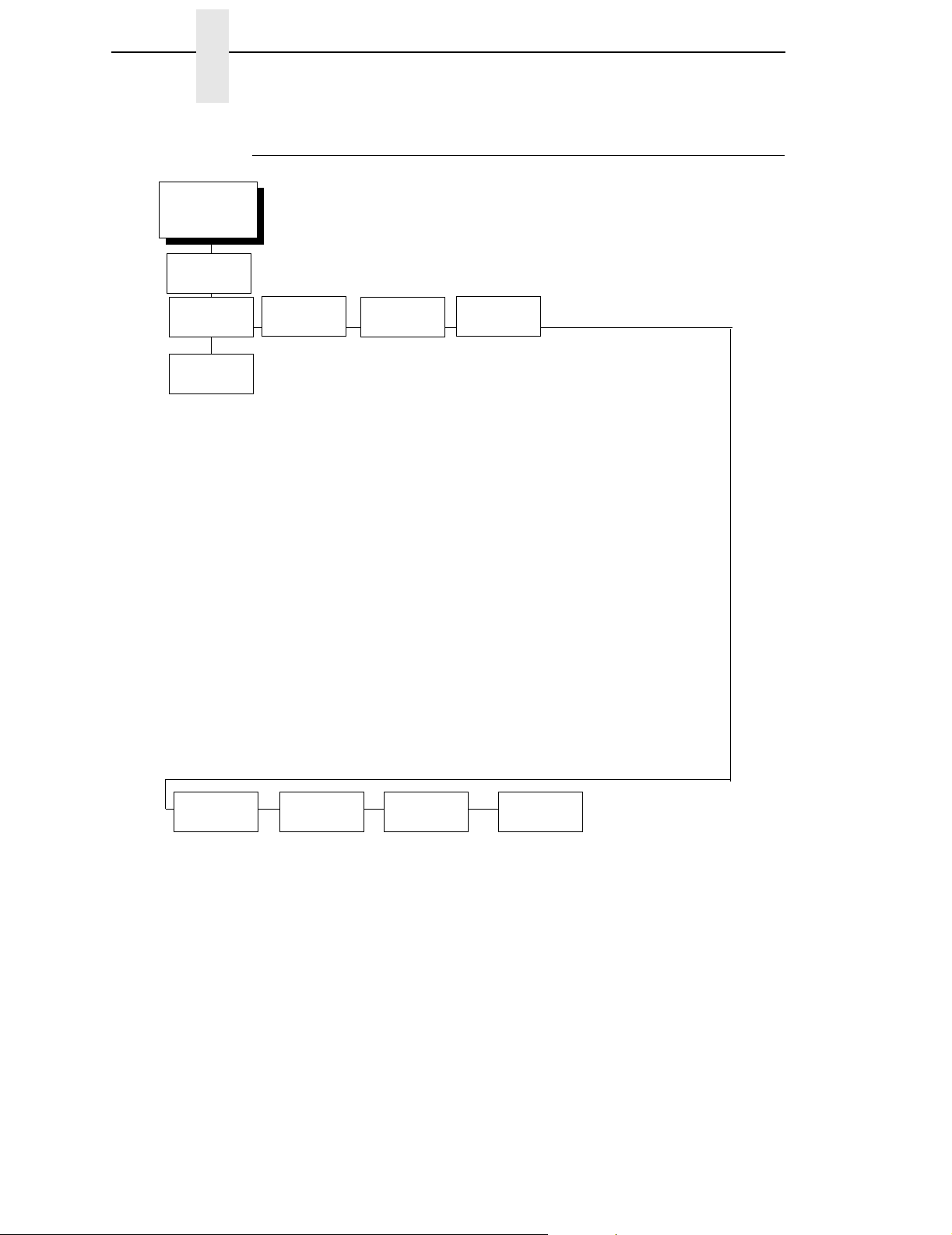
Chapter 4 EMULATION
Hanzi Big5 LP+ Emulation
EMULATION
(from page 50)
LinePrinter+
Printer
Protocol
LQ-1600K
CPI/LPI
Select
Select CPI
10.0 CPI*
12.0 CPI
13.3 CPI
15.0 CPI
17.1 CPI
20.0 CPI
Select LPI
6.0 LPI*
8.0 LPI
DBCS CPI
5.0 CPI
6.0 CPI
6.7 CPI*
7.5 CPI
Other CPI
Host
Command
Enable
Ignore All
Ignore CPI
Ignore LPI
Ignore Unidir*
Font
Attributes
Typeface
LQ*
Near LQ
Normal
Hi-Speed
Super Hi-Speed
Ultra Hi-Speed
Styling Type
MING*
High Density
Disable*
Enable
Prop. Spacing
Disable*/Enable
Bold Print
Disable*/Enable
Italic Print
Disable*
Forward Slant
Backward Slant
Slashed Zero
Disable*/Enable
DBCS/ASCII Mode
DBCS Mode*
ASCII Mode
* = Factory Default
DBCS ASCII Style
Normal*
Oversize
OCRB
Text Position
Bottom of Line*
Top of Line
Compressed Mode
Disable*
Enable
DBCS Compressed
Disable*
Enable
Encoding
Address Table*
UTF8
Taller 15 CPI
Disable*
Enable
Horizontal Expnd
24* pt size
(24 - 72) pt size
Vertical Expnd
24* pt size
(24 - 72) pt size
92
Graphics
Spd Up
Normal
Enhanced
Turbo
Match Typeface*
Page
Format
See page 98.
Reset Cmd
CFG Ld
Disable
Power up Config.
Current Config.*
Factory Config.
Error
Handling
Illegal Code Pt.
Normal
As Space*
As Square
Page 93

Kanji LP+ Emulation
Kanji LP+ Emulation
EMULATION
(from page 50)
LinePrinter+
Printer
Protocol
LQ-1600K
CPI/LPI
Select
Select CPI
10.0 CPI
12.0 CPI
13.3 CPI
15.0 CPI*
17.1 CPI
20.0 CPI
Select LPI
6.0 LPI
8.0 LPI*
DBCS CPI
5.0 CPI
6.0 CPI
6.7 CPI
7.5 CPI*
Other CPI
Host
Command
Enable
Ignore All
Ignore CPI
Ignore LPI
Ignore Unidir*
Font
Attributes
Typeface
LQ
Near LQ*
Normal
Hi-Speed
Super Hi-Speed
Ultra Hi-Speed
Styling Type
Mincho*
High Density
Disable*
Enable
Prop. Spacing
Disable*/Enable
Bold Print
Disable*/Enable
Italic Print
Disable*
Forward Slant
Backward Slant
Slashed Zero
Disable*/Enable
DBCS/ASCII Mode
DBCS Mode*
ASCII Mode
* = Factory Default
DBCS ASCII Style
Normal*
Oversize
OCRB
Text Position
Bottom of Line*
Top of Line
Compressed Mode
Disable*
Enable
DBCS Compressed
Disable*
Enable
Encoding
Address Table*
UTF8
Taller 15 CPI
Disable*
Enable
Horizontal Expnd
24* pt size
(24 - 72) pt size
Vertical Expnd
24* pt size
(24 - 72) pt size
Graphics
Spd Up
Normal*
Enhanced
Turbo
Match Typeface
Page
Format
See page 98.
Reset Cmd
CFG Ld
Disable*
Power up Config.
Current Config.
Factory Config.
Error
Handling
Illegal Code Pt.
Normal*
As Space
93
Page 94

Chapter 4 EMULATION
Hangul LP+ Emulation
EMULATION
(from page 50)
LinePrinter+
Printer
Protocol
KS*
KSSM.
CPI/LPI
Select
Select CPI
10.0 CPI*
12.0 CPI
13.3 CPI
15.0 CPI
17.1 CPI
20.0 CPI
Select LPI
6.0 LPI
8.0 LPI*
DBCS CPI
5.0 CPI
6.0 CPI*
6.7 CPI
7.5 CPI
8.5 CPI
9.0 CPI
10.0 CPI
Other CPI
1
Host
Command
Enable*
Ignore All
Ignore CPI
Ignore LPI
Ignore Unidir
Ignore Pg. Fmt
Font
Attributes
Typeface
LQ*
Near LQ
Normal
Hi-Speed
Super Hi-Speed
Ultra Hi-Speed
Styling Type
Myungjo*
Gothic
High Density
Disable*
Enable
Bold Print
Disable*/Enable
Italic Print
Disable*
Forward Slant
Backward Slant
Slashed Zero
Disable*/Enable
DBCS/ASCII Mode
DBCS Mode*
ASCII Mode
* = Factory Default
1 = Hangul KSSM only
DBCS ASCII Style
Normal*
OCRB
Normal Thin
Text Position
Bottom of Line*
Top of Line
Encoding
Address Table*
UTF8
Taller 15 CPI
Disable*
Enable
Horizontal Expnd
24* pt size
(24 - 72) pt size
Vertical Expnd
24* pt size
(24 - 72) pt size
1
1
94
Graphics
Spd Up
Normal*
Enhanced
Turbo
Match Typeface
Printer Protocol
For the Hanzi LP+ printer, refer to the the LQ-1600K Programmer’s
Reference Manual for details. For the Hangul LP+ printer, refer to the KS or
KSSM Programmer’s Reference Manual for details.
Page
Format
See page 98.
Reset Cmd
CFG Ld
Disable*
Power up Config.
Current Config.
Factory Config.
Error
Handling
Illegal Code Pt.
Normal*
As Space
Page 95

Hangul LP+ Emulation
CPI/LPI Select
This parameter lets you specify the characters per inch (cpi) and lines per
inch (lpi) values. The defaults are 10 cpi, 6 lpi, and 6.7 cpi for the Hanzi LP+
printer. For the Hangul LP+ printer, the default is 6 cpi and 6 lpi. For the Kanji
LP+ printer, the default is 15 cpi, 8 lpi, and 7.5 cpi.
Host Command
• Enable. Enables all host printing commands.
• Ignore All. This function treats all control codes and printing commands
as the data.
• Ignore CPI. This function ignores the CPI selection commands only (e.g.,
ESC M, ESC P, and ESC G).
• Ignore LPI. This function ignores the LPI selection commands only (e.g,
ESC 2 and ESC 0).
• Ignore Unidirectional (the default). All unidirectional commands sent by
the host are ignored by the printer.
• Ignore Pg. Fmt. All page format commands sent by the host are ignored
by the printer. This is applicable only for Hangul LP+ printers only.
Font Attributes
This submenu allows you to define the following font attributes: typeface,
proportional spacing, bold print, and italic print. You can also specify if the
zero character will print with a slash.
For the Hanzi GB and Kanji LP+ printer, the default typeface is Near LQ. For
the Hangul and Hanzi Big5 LP+ printer, the default is LQ.
High Density enabled will allow the LQ typeface to print in higher print density.
It will not take effect when other typefaces are selected.
Text position specifies where the text will be positioned in the line space.
When set to Top of Line, text will be positioned at the top of the line space.
When set to Bottom of Line, the text will be positioned as if it were at the
bottom of a 6 lpi line space. The following example shows both Top of Line
and Bottom of Line text positions:
Dot
Top of Linespace
Bottom of 8 LPI Linespace
Bottom of 6 LPI Linespace
Row
1
2
3
4
5
6
7
8
9
10
11
12
Text Position
Top of Line
1
Text Position
Bottom of Line
95
Page 96

Chapter 4 EMULATION
The option “DBCS / ASCII mode” specifies the operating mode of the Hanzi
printer. If it is set to DBCS mode, it can print double-byte characters as well as
a limited number of single-byte characters. Otherwise, it can only print singlebyte characters.
The option “DBCS ASCII Style” specifies the appearance of the single-byte
numeric characters. If it is set to Oversize, the numeric characters will appear
larger than other single-byte characters. For example, the appearance of
character “8” will be changed to “
characters will print in OCRB style.
The option “Compressed Mode” in the Hanzi printer specifies the appearance
of ASCII characters and DBCS characters in ASCII mode. If it is set to
“Enable,” it can print out ASCII mode ASCII char and half width DBCS
characters.
The option “DBCS Compressed” specifies the appearance of DBCS and
ASCII characters in DBCS mode. If set to “Enable,” both the DBCS and ASCII
characters will print at half of the width of their original size. This is not
applicable for Hangul printers.
The option “Address Table” specifies the address table supported:
8.” If it is set to OCRB, the numeric
• GB18030 for the Hanzi GB printer
• BIG5 (default), CNS, TCA, ETEN, IBM5550, TELETEXT, WANG, BIG5+,
BIG5E, and HKSCS-2001 for Hanzi Big5 printer.
• KSC5601 for the Hangul printer
• Shift-JIS for the Kanji printer
The UTF8 option allows users to input UTF8 data stream.
The Taller 15cpi option specifies the appearance of ASCII characters as 15cpi
in ASCII mode. If set to Enable, the characters in 15cpi will be the same
height as other CPIs such as 10cpi. If set to Disable, the characters in 15cpi
appears shorter than other CPIs such as 10cpi.
The Horizontal Expnd option specifies dot character horizontal expansion for
both ASCII and DBCS characters in DBCS mode.
The Vertical Expnd option specifies dot character vertical expansin for both
ASCII and DBCS characters in DBCS mode.
Graphics Spd Up
This menu is used to increase (speed up) graphic printing speed by turning on
the Enhanced/Turbo mode.
• Normal (the default). The printer prints at the given input graphics
resolution.
96
• Enhanced. The printer provides first-level speed up, which means the
speed is faster than Normal mode.
• Turbo. The printer provides second-level speed up, which means the
speed is faster than Enhanced mode.
• Match Typeface. The input 180x180 dpi graphics resolution will drop-dot
to the resolution which matches the typeface selected.
Page 97

Hangul LP+ Emulation
Page Format
See page 98.
Reset Cmd CFG Ld
When the printer receives a host data stream reset command (ESC @ or
ESC[K) in addition to resetting printer variables, the power-up configuration
will be loaded.
• Disable (the default). The factory configuration is loaded when the reset
command is executed.
• Power-Up Config. The power-up configuration is loaded when the reset
command is executed.
• Current Config. The currently selected configuration is loaded when the
reset command is executed.
• Factory Config. The factory installed configuration is loaded when the
reset command is executed.
Error Handling
This command determines the way illegal DBCS characters are processed:
• Normal (the default). Will ignore illegal DBCS characters.
• As Space. Will insert two space characters (0X20, 0X20) when the data
stream contains error DBCS coding.
• As Square. Will insert a black square (0xAIBD) when the data stream
contains error DBCS coding. This is applicable for the Hanzi Big5 build
only.
97
Page 98

Chapter 4 EMULATION
Page Format Submenu
Page Format
(from page 91)
Margins
Left Margin
0* columns
(0-369)
Right Margin
0* columns
(0-369)
Bottom Margin
0* lines
(0-451)
* = Factory Default for Hanzi and Hangul printer
** = Factory Default for Kanji printer
Perforation
Skip
Disable*
1/2 inch
2/3 inch
5/6 inch
1 inch
Form
Length
Abs. Length IN
11.0* inches
08.5** inches
(0.1-24)
Abs. Length MM
279.4* mm
215.9** mm
(0.1-609.6)
Funct. of Lines
66* Lines
68** Lines
(1-192)
Form
Width
Abs. Width IN
13.6* inches
(0.1-13.6)
Abs. Width MM
345.5* mm
(0.1-345.5)
Funct. of CPI
136* Characters
204** Characters
(1-272)
Page Format
• Margins. You can set the bottom, left, and right form margins.
• Perforation Skip. Allows or prevents printing on page perforation. When
enabled, it sets up a skip-over margin of
1/2,” 2/3,” 5/6,” or 1.” For example, a skip-over margin of 1” allows a 1”
margin at the bottom of the page perforation. The default is Disable.
• Form Length. The number of lines that can be printed on a page. You
can set forms length in inches or in print lines per page. The most
accurate method is lines per page.
• Form Width. When using paper which is 8-1/2” wide, selecting an 8” print
width prevents printing beyond the right margin and damaging the
hammer tips and platen.
98
Page 99

PRINTER CONTROL
PRINTER CONTROL
Page Format Submenu
PRINTER
CONTROL
(from page 50)
Ribbon End
Point
Darker +6
Darker +5
Darker +4
Darker +3
Darker +2
Darker +1
Normal
Lighter -1
Lighter -2
Lighter -3
Lighter -4
Lighter -5
Lighter -6
Lighter -7*
Lighter -8
Lighter -9
Lighter -10
Open Platen
@BOF
Enable
* = Factory Default
1
Tear Bar
Dist.
7.46 inches.*
(4.5 - 10.5)
Function
Disable*
Enable
Ribbon End Point
Available only for P7000 pedestal model
View
Unidirectional Display
1
Disable*
Enable
Language
English*Disable*
Accented
Char
Standard*
Tall
This parameter adjusts the point at which the system will declare the ribbon
as being expended. The life count will always be from 100% to 0%, but if a
darker setting is selected 0% will be reached more quickly. If a lighter setting
is selected, the system will extend the time it takes to reach 0%. The range of
values are as follows:
• Normal
• Darker +1 through Darker +6
• Lighter -1 through Lighter -10
(Lighter -7 is the default)
NOTE: This value can be adjusted at any time and the display will
automatically adjust to show the correct percentage relative to the
new end point.
Open Platen @ BOF (Bottom of Form)
Some special forms have perforation areas that are too thick to pass through
the print station. This parameter, when enabled, opens and closes the platen
when the perforations move across the platen. When enabling this parameter,
you must set the forms length to match the physical distance between
perforations.
99
Page 100

Chapter 4 PRINTER CONTROL
Tear Bar Dist. (Distance)
Allows fine and course adjustment of the tear bar position. For a pedestal
model printer using the top paper exit, the default
(7.46 inches) is used. You can specify 4.5 to 10.5 inches in .01 inch
increments to accommodate variations in cover and form design.
View Function
• Disable (default). Disables the View Function which allows you to press
the VIEW/EJECT key to move the last data printed to the tractor area for
viewing.
• Enable. Enables the View Function
Unidirectional
The Unidirectional feature affects both print quality and printing speed. By
setting this feature, you can configure the printer to print in both directions of
the shuttle sweep (bidirectional), or to print in one direction only
(unidirectional).
• Disable (default). The printer will print all data in both directions of the
shuttle sweep (bidirectional printing). This choice produces higher printing
speed.
• Enable. The printer will print all data in only one direction of the shuttle
sweep (unidirectional printing). Although enabling this feature reduces
print speed, it enhances the vertical alignment of dots and produces
cleaner, sharper barcodes and text.
Display Language
This parameter chooses the language that will appear on the LCD: English.
Accented Char
Selects whether the accented characters are standard or tall. See Figure 23
for an example. Selecting tall will slow print speed and may cause the printer
to back up during printing.
100
Standard
Figure 23. Accented Characters
Tall
 Loading...