

Page 1
R
User's Reference Manual
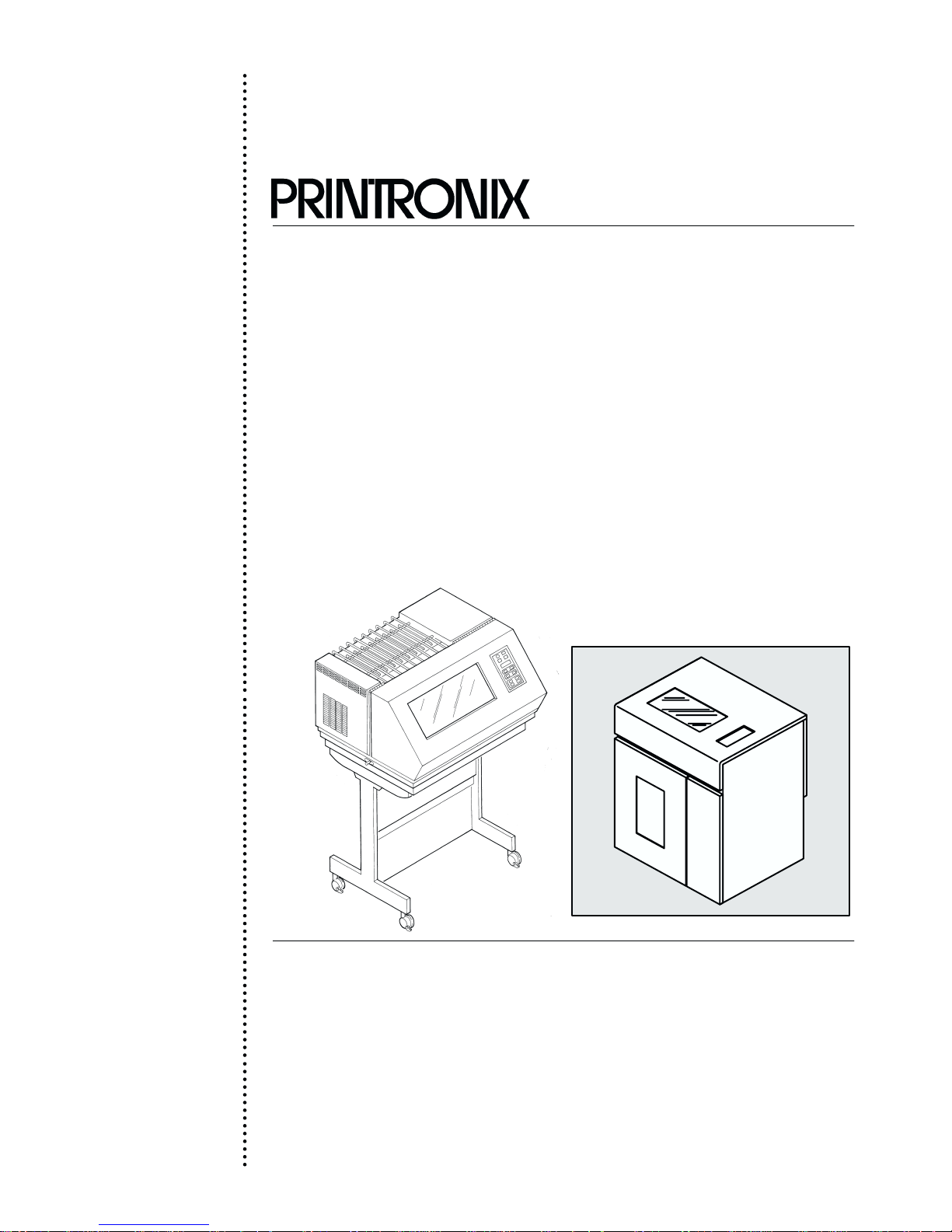
P600L/P6200L Line Printers
Page 2

Page 3

P6000L/P6200L Line Printers
User's Reference Manual
P/N 140576–001, Rev C
R
Page 4

US and CANADA Radio Interference Note
This device complies with Part 15 of the FCC Rules. Operation is subject to the following two conditions: (1) this
Note:
device may not cause harmful interference, and (2) this device must accept any interference received, including
interference that may cause undesired operation.
Properly shielded and grounded cables and connectors must be used in order to meet FCC emission limits. The
manufacturer is not responsible for any radio or television interference caused by using other than recommended
cables and connectors or by unauthorized changes or modifications to this equipment. Unauthorized changes or
modifications could void the user’s authority to operate the equipment.
The input/output (I/O) cable must be shielded for the printer to comply with FCC rules and regulations Part 15
governing the radiation limits for Class “A” equipment.
This Class A digital apparatus meets all requirements of the Canadian Interference–Causing Equipment Regulations.
Cet appareil numérique de la classe A respecte toutes les exigences du Règlement sur le matériel brouilleur du
Canada.
WARNING
This is a Class A product. In a domestic environment this product may cause radio interference in which case the user
may be required to take adequate measures.
Printronix, Inc. makes no representations or warranties of any kind regarding this material, including, but not limited to,
implied warranties of merchantability and fitness for a particular purpose. Printronix, Inc. shall not be held responsible
for errors contained herein or any omissions from this material or for any damages, whether direct, indirect, incidental
or consequential, in connection with the furnishing, distribution, performance or use of this material. The information in
this manual is subject to change without notice.
This document contains proprietary information protected by copyright. No part of this document may be reproduced,
copied, translated or incorporated in any other material in any form or by any means, whether manual, graphic,
electronic, mechanical or otherwise, without the prior written consent of Printronix, Inc.
All rights reserved. Revision C. January 1996.
Trademark Acknowledgements
The following trademarks are hereby acknowledged:
IBM is a registered trademark of International Business Machines.
QMS is a registered trademark of Quality Micro Systems, Inc.
Epson is a registered trademark of Epson America, Inc.
Printronix is a registered trademark of Printronix, Inc.
IGP is a trademark of Printronix, Inc.
RibbonMinder is a trademark of Printronix, Inc.
17500 Cartwright Road, P.O. Box 19559
Irvine, California 92713
Telephone (714) 863–1900 FAX (714) 660–8682
Technical Support (714) 221–2686
COPYRIGHT 1988, 1989, 1996, PRINTRONIX, INC.
Page 5

TABLE OF CONTENTS
Chapter
1 Overview
Introduction 1-1. . . . . . . . . . . . . . . . . . . . . . . . . . . . . . . . . . . . . . . . . . . . . . . . . . . . . . . . . . . . . . . . . . . . . . . . .
Features 1-1. . . . . . . . . . . . . . . . . . . . . . . . . . . . . . . . . . . . . . . . . . . . . . . . . . . . . . . . . . . . . . . . . . . . . . . . . . . . .
Optional F
Character F
Dot Matrix Line P
P
rint R
Plot R
eatures 1-2. . . . . . . . . . . . . . . . . . . . . . . . . . . . . . . . . . . . . . . . . . . . . . . . . . . . . . . . . . . . . . . . . . . .
ormation 1-3. . . . . . . . . . . . . . . . . . . . . . . . . . . . . . . . . . . . . . . . . . . . . . . . . . . . . . . . . . . . . . . . . .
rinting 1-4. . . . . . . . . . . . . . . . . . . . . . . . . . . . . . . . . . . . . . . . . . . . . . . . . . . . . . . . . . . . . . .
ate 1-5. . . . . . . . . . . . . . . . . . . . . . . . . . . . . . . . . . . . . . . . . . . . . . . . . . . . . . . . . . . . . . . . . . . . . . . . . . .
ate 1-5. . . . . . . . . . . . . . . . . . . . . . . . . . . . . . . . . . . . . . . . . . . . . . . . . . . . . . . . . . . . . . . . . . . . . . . . . . . .
2 Operation
Introduction 2-1. . . . . . . . . . . . . . . . . . . . . . . . . . . . . . . . . . . . . . . . . . . . . . . . . . . . . . . . . . . . . . . . . . . . . . . . .
ower Switch
P
L
ocking/Unlocking P
Control P
aper A
P
L
oading P
Unloading P
Setting T
aper Stacking - Floor Cabinet Models
P
Selecting P
L
oading the Ribbon
Setting F
Setting Line Spacing
Hex Code Printout 2-23. . . . . . . . . . . . . . . . . . . . . . . . . . . . . . . . . . . . . . . . . . . . . . . . . . . . . . . . . . . . . . . . . . . .
P
rinter R
unning the Self-T
R
anel 2-4. . . . . . . . . . . . . . . . . . . . . . . . . . . . . . . . . . . . . . . . . . . . . . . . . . . . . . . . . . . . . . . . . . . . . . . .
djustment Controls
aper 2-12. . . . . . . . . . . . . . . . . . . . . . . . . . . . . . . . . . . . . . . . . . . . . . . . . . . . . . . . . . . . . . . . . . . . . . .
aper 2-13. . . . . . . . . . . . . . . . . . . . . . . . . . . . . . . . . . . . . . . . . . . . . . . . . . . . . . . . . . . . . . . . . . . . .
op-of-Form 2-15. . . . . . . . . . . . . . . . . . . . . . . . . . . . . . . . . . . . . . . . . . . . . . . . . . . . . . . . . . . . . . . . .
rint Mode
orms L
eset 2-24. . . . . . . . . . . . . . . . . . . . . . . . . . . . . . . . . . . . . . . . . . . . . . . . . . . . . . . . . . . . . . . . . . . . . . . . .
rinter Configuration
ength 2-21. . . . . . . . . . . . . . . . . . . . . . . . . . . . . . . . . . . . . . . . . . . . . . . . . . . . . . . . . . . . . . . . .
est 2-24. . . . . . . . . . . . . . . . . . . . . . . . . . . . . . . . . . . . . . . . . . . . . . . . . . . . . . . . . . . . . . . . .
Page
2-2. . . . . . . . . . . . . . . . . . . . . . . . . . . . . . . . . . . . . . . . . . . . . . . . . . . . . . . . . . . . . . . . . . . . . . . . .
2-4. . . . . . . . . . . . . . . . . . . . . . . . . . . . . . . . . . . . . . . . . . . . . . . . .
2-7. . . . . . . . . . . . . . . . . . . . . . . . . . . . . . . . . . . . . . . . . . . . . . . . . . . . . . . . . . . . .
2-16. . . . . . . . . . . . . . . . . . . . . . . . . . . . . . . . . . . . . . . . . . . . . . . . . .
2-19. . . . . . . . . . . . . . . . . . . . . . . . . . . . . . . . . . . . . . . . . . . . . . . . . . . . . . . . . . . . . . . . . .
2-20. . . . . . . . . . . . . . . . . . . . . . . . . . . . . . . . . . . . . . . . . . . . . . . . . . . . . . . . . . . . . . . . . . .
2-22. . . . . . . . . . . . . . . . . . . . . . . . . . . . . . . . . . . . . . . . . . . . . . . . . . . . . . . . . . . . . . . . . .
3 Configuration
Introduction 3-1. . . . . . . . . . . . . . . . . . . . . . . . . . . . . . . . . . . . . . . . . . . . . . . . . . . . . . . . . . . . . . . . . . . . . . . . .
L
ocking/Unlocking P
Configuration Menus
Configuration P
Set/Save/Load Configuration Values 3-3. . . . . . . . . . . . . . . . . . . . . . . . . . . . . . . . . . . . . . . . . . . . . . . . . . . . .
Set V
alues 3-3. . . . . . . . . . . . . . . . . . . . . . . . . . . . . . . . . . . . . . . . . . . . . . . . . . . . . . . . . . . . . . . . . . . . . . . . . .
Saved Values 3-3. . . . . . . . . . . . . . . . . . . . . . . . . . . . . . . . . . . . . . . . . . . . . . . . . . . . . . . . . . . . . . . . . . . . . . . .
Load Values 3-4. . . . . . . . . . . . . . . . . . . . . . . . . . . . . . . . . . . . . . . . . . . . . . . . . . . . . . . . . . . . . . . . . . . . . . . . .
Default Configuration Values 3-5. . . . . . . . . . . . . . . . . . . . . . . . . . . . . . . . . . . . . . . . . . . . . . . . . . . . . . . . . . .
Configuration P
Hardware Jumper Configuration
P6000L/P6200L User's Reference Manual i
rinter Configuration
rocedure 3-2. . . . . . . . . . . . . . . . . . . . . . . . . . . . . . . . . . . . . . . . . . . . . . . . . . . . . . . . . . . . . . .
rintout 3-6. . . . . . . . . . . . . . . . . . . . . . . . . . . . . . . . . . . . . . . . . . . . . . . . . . . . . . . . . . . . . . . .
3-1. . . . . . . . . . . . . . . . . . . . . . . . . . . . . . . . . . . . . . . . . . . . . . . . .
3-1. . . . . . . . . . . . . . . . . . . . . . . . . . . . . . . . . . . . . . . . . . . . . . . . . . . . . . . . . . . . . . . . . .
3-8. . . . . . . . . . . . . . . . . . . . . . . . . . . . . . . . . . . . . . . . . . . . . . . . . . . . . . . .
Page 6

Side P
anel R
emoval - Floor Cabinet Model 3-8. . . . . . . . . . . . . . . . . . . . . . . . . . . . . . . . . . . . . . . . . . . . .
Chapter
3 Configuration (continued)
Removing
Control P
Level I - P
Level II - Main Configuration Menus 3-14. . . . . . . . . . . . . . . . . . . . . . . . . . . . . . . . . . . . . . . . . . . . . . . . . .
Level III - Configuration Menu Parameters 3-14. . . . . . . . . . . . . . . . . . . . . . . . . . . . . . . . . . . . . . . . . . . . .
the PCBA - Floor Cabinet Model
anel Configuration Diagram
rint F
ormat 3-14. . . . . . . . . . . . . . . . . . . . . . . . . . . . . . . . . . . . . . . . . . . . . . . . . . . . . . . . . . . . . . . .
4 Graphics
Introduction 4-1. . . . . . . . . . . . . . . . . . . . . . . . . . . . . . . . . . . . . . . . . . . . . . . . . . . . . . . . . . . . . . . . . . . . . . . . .
Serial Matrix Compatible Bit Image Graphics
Plotting a Bit Image P
Bit Image Density
Bit Image P
P-Series Compatible Plot Mode
Plot Density
Plot Data Line F
Plot Data Byte F
Plotting the Data
Combining Graphics and T
rogramming F
attern 4-3. . . . . . . . . . . . . . . . . . . . . . . . . . . . . . . . . . . . . . . . . . . . . . . . . . . . . . . . . . .
ormat 4-5. . . . . . . . . . . . . . . . . . . . . . . . . . . . . . . . . . . . . . . . . . . . . . . . . . . . . . . .
ormat 4-8. . . . . . . . . . . . . . . . . . . . . . . . . . . . . . . . . . . . . . . . . . . . . . . . . . . . . . . . . . . . . . . .
ormat 4-9. . . . . . . . . . . . . . . . . . . . . . . . . . . . . . . . . . . . . . . . . . . . . . . . . . . . . . . . . . . . . . . .
ext 4-12. . . . . . . . . . . . . . . . . . . . . . . . . . . . . . . . . . . . . . . . . . . . . . . . . . . . . . . . . . .
Page
3-9. . . . . . . . . . . . . . . . . . . . . . . . . . . . . . . . . . . . . . . . . . . . .
3-14. . . . . . . . . . . . . . . . . . . . . . . . . . . . . . . . . . . . . . . . . . . . . . . . . . . .
4-1. . . . . . . . . . . . . . . . . . . . . . . . . . . . . . . . . . . . . . . . . . . . .
4-4. . . . . . . . . . . . . . . . . . . . . . . . . . . . . . . . . . . . . . . . . . . . . . . . . . . . . . . . . . . . . . . . . . . .
4-7. . . . . . . . . . . . . . . . . . . . . . . . . . . . . . . . . . . . . . . . . . . . . . . . . . . . . . . .
4-7. . . . . . . . . . . . . . . . . . . . . . . . . . . . . . . . . . . . . . . . . . . . . . . . . . . . . . . . . . . . . . . . . . . . . . . . .
4-11. . . . . . . . . . . . . . . . . . . . . . . . . . . . . . . . . . . . . . . . . . . . . . . . . . . . . . . . . . . . . . . . . . . . .
5 Vertical Format Units
Introduction 5-1. . . . . . . . . . . . . . . . . . . . . . . . . . . . . . . . . . . . . . . . . . . . . . . . . . . . . . . . . . . . . . . . . . . . . . . . .
DAVFU 5-1. . . . . . . . . . . . . . . . . . . . . . . . . . . . . . . . . . . . . . . . . . . . . . . . . . . . . . . . . . . . . . . . . . . . . . . . . . . . .
General DA
Start L
Channel Assignment
End L
Using The D
Clearing The DAVFU Memory
DAVFU/IGP Execute F
DA
VFU Line Slewing
P-Series EVFU
General P-Series EVFU P
P-Series EVFU Command and Channel Codes
P-Series EVFU F
Serial Emulation VFU
Executing V
V
ertical T
VFU P
rogramming 5-1. . . . . . . . . . . . . . . . . . . . . . . . . . . . . . . . . . . . . . . . . . . . . . . . . . . . . . . .
oad Code - 6E Hex 5-2. . . . . . . . . . . . . . . . . . . . . . . . . . . . . . . . . . . . . . . . . . . . . . . . . . . . . . . . . . . .
oad Code - 6F Hex 5-4. . . . . . . . . . . . . . . . . . . . . . . . . . . . . . . . . . . . . . . . . . . . . . . . . . . . . . . . . . . . .
AVFU 5-4. . . . . . . . . . . . . . . . . . . . . . . . . . . . . . . . . . . . . . . . . . . . . . . . . . . . . . . . . . . . . . . . . . .
orm Mode
rogramming Information
orm Definition P
ertical T
ab P
abs 5-14. . . . . . . . . . . . . . . . . . . . . . . . . . . . . . . . . . . . . . . . . . . . . . . . . . . . . . . . . . . . . . .
ositions 5-14. . . . . . . . . . . . . . . . . . . . . . . . . . . . . . . . . . . . . . . . . . . . . . . . . . . . . . . . . . . . . . . . .
rogram 5-10. . . . . . . . . . . . . . . . . . . . . . . . . . . . . . . . . . . . . . . . . . . . . . .
5-2. . . . . . . . . . . . . . . . . . . . . . . . . . . . . . . . . . . . . . . . . . . . . . . . . . . . . . . . . . . . . . . . . .
5-4. . . . . . . . . . . . . . . . . . . . . . . . . . . . . . . . . . . . . . . . . . . . . . . . . . . . . . . . .
5-5. . . . . . . . . . . . . . . . . . . . . . . . . . . . . . . . . . . . . . . . . . . . . . . . . . . . . .
5-6. . . . . . . . . . . . . . . . . . . . . . . . . . . . . . . . . . . . . . . . . . . . . . . . . . . . . . . . . . . . . . . . .
5-7. . . . . . . . . . . . . . . . . . . . . . . . . . . . . . . . . . . . . . . . . . . . . . . . . . . . . . . . . . . . . . . . . . . . . .
5-7. . . . . . . . . . . . . . . . . . . . . . . . . . . . . . . . . . . . . .
5-8. . . . . . . . . . . . . . . . . . . . . . . . . . . . . . . . . . . . . . . . . .
5-14. . . . . . . . . . . . . . . . . . . . . . . . . . . . . . . . . . . . . . . . . . . . . . . . . . . . . . . . . . . . . . . . .
ii P6000L/P6200L User's Reference Manual
Page 7

Chapter
6 Programming
Introduction 6-1. . . . . . . . . . . . . . . . . . . . . . . . . . . . . . . . . . . . . . . . . . . . . . . . . . . . . . . . . . . . . . . . . . . . . . . . .
Overstrike Mode 6-1. . . . . . . . . . . . . . . . . . . . . . . . . . . . . . . . . . . . . . . . . . . . . . . . . . . . . . . . . . . . . . . . . . . . .
Control Code F
Special F
A
ttribute Set and R
Control Code R
Backspace 6-5. . . . . . . . . . . . . . . . . . . . . . . . . . . . . . . . . . . . . . . . . . . . . . . . . . . . . . . . . . . . . . . . . . . . . . . . . . .
Bell 6-6. . . . . . . . . . . . . . . . . . . . . . . . . . . . . . . . . . . . . . . . . . . . . . . . . . . . . . . . . . . . . . . . . . . . . . . . . . . . . . . . .
Bit Image Mode, Single Density
Bit Image Mode, Double Density
Bit Image Mode, Double Density Double Speed
Bit Image Mode, Quadruple Density
Bold P
rint 6-11. . . . . . . . . . . . . . . . . . . . . . . . . . . . . . . . . . . . . . . . . . . . . . . . . . . . . . . . . . . . . . . . . . . . . . . . . . .
Bold P
rint R
Cancel 6-13. . . . . . . . . . . . . . . . . . . . . . . . . . . . . . . . . . . . . . . . . . . . . . . . . . . . . . . . . . . . . . . . . . . . . . . . . . . . . .
Carriage R
Character Set Select (Control Codes)
Character Set Select (P
Condensed P
Condensed P
Elongated (Double High) P
Emphasized P
Emphasized P
EVFU Commands (P-Series)
Expanded (Double W
Expanded (Double W
Extended Character Set
Extended Character Set Cancel
(P
rimary Character Set Select)
F
orm F
eed 6-27. . . . . . . . . . . . . . . . . . . . . . . . . . . . . . . . . . . . . . . . . . . . . . . . . . . . . . . . . . . . . . . . . . . . . . . . . . .
F
orms L
F
orms L
Horizontal T
Horizontal T
International Character Set Select
Line F
Line F
Line Spacing 1/6 Inch
Line Spacing 1/8 Inch (8 lpi)
Line Spacing 8 lpi (One Line Only)
Line Spacing 7/72 Inch
Line Spacing n/72 Inch (Asserted)
Line Spacing n/72 Inch (Stored)
ength Set (Inches)
ength Set (Lines)
eed 6-33. . . . . . . . . . . . . . . . . . . . . . . . . . . . . . . . . . . . . . . . . . . . . . . . . . . . . . . . . . . . . . . . . . . . . . . . . . .
eed n/216 Inch (one line only)
unctions 6-2. . . . . . . . . . . . . . . . . . . . . . . . . . . . . . . . . . . . . . . . . . . . . . . . . . . . . . . . . . . . . . .
unction Code - Control Code Header
eset Codes
eference Index
eset 6-12. . . . . . . . . . . . . . . . . . . . . . . . . . . . . . . . . . . . . . . . . . . . . . . . . . . . . . . . . . . . . . . . . . . . . .
eturn 6-14. . . . . . . . . . . . . . . . . . . . . . . . . . . . . . . . . . . . . . . . . . . . . . . . . . . . . . . . . . . . . . . . . . . . . .
rintable Symbols)
rint 6-17. . . . . . . . . . . . . . . . . . . . . . . . . . . . . . . . . . . . . . . . . . . . . . . . . . . . . . . . . . . . . . . . . . . . . .
rint R
eset 6-18. . . . . . . . . . . . . . . . . . . . . . . . . . . . . . . . . . . . . . . . . . . . . . . . . . . . . . . . . . . . . . . .
rint 6-19. . . . . . . . . . . . . . . . . . . . . . . . . . . . . . . . . . . . . . . . . . . . . . . . . . . . . . . . .
rint 6-20. . . . . . . . . . . . . . . . . . . . . . . . . . . . . . . . . . . . . . . . . . . . . . . . . . . . . . . . . . . . . . . . . . . . .
rint R
eset 6-21. . . . . . . . . . . . . . . . . . . . . . . . . . . . . . . . . . . . . . . . . . . . . . . . . . . . . . . . . . . . . . .
ide) P
rint 6-23. . . . . . . . . . . . . . . . . . . . . . . . . . . . . . . . . . . . . . . . . . . . . . . . . . . . . . . . .
ide) P
rint (One Line Only)
ab 6-30. . . . . . . . . . . . . . . . . . . . . . . . . . . . . . . . . . . . . . . . . . . . . . . . . . . . . . . . . . . . . . . . . . . . . . .
ab Set
Page
6-2. . . . . . . . . . . . . . . . . . . . . . . . . . . . . . . . . . . . . . . . . . .
6-2. . . . . . . . . . . . . . . . . . . . . . . . . . . . . . . . . . . . . . . . . . . . . . . . . . . . . . . . . .
6-3. . . . . . . . . . . . . . . . . . . . . . . . . . . . . . . . . . . . . . . . . . . . . . . . . . . . . . . . . .
6-7. . . . . . . . . . . . . . . . . . . . . . . . . . . . . . . . . . . . . . . . . . . . . . . . . . . . . . . . .
6-8. . . . . . . . . . . . . . . . . . . . . . . . . . . . . . . . . . . . . . . . . . . . . . . . . . . . . . . .
6-9. . . . . . . . . . . . . . . . . . . . . . . . . . . . . . . . . . . . . . . . . . .
6-10. . . . . . . . . . . . . . . . . . . . . . . . . . . . . . . . . . . . . . . . . . . . . . . . . . . . .
6-15. . . . . . . . . . . . . . . . . . . . . . . . . . . . . . . . . . . . . . . . . . . . . . . . . . . .
6-16. . . . . . . . . . . . . . . . . . . . . . . . . . . . . . . . . . . . . . . . . . . . . . . . .
6-22. . . . . . . . . . . . . . . . . . . . . . . . . . . . . . . . . . . . . . . . . . . . . . . . . . . . . . . . . .
6-24. . . . . . . . . . . . . . . . . . . . . . . . . . . . . . . . . . . . . . . . . .
6-25. . . . . . . . . . . . . . . . . . . . . . . . . . . . . . . . . . . . . . . . . . . . . . . . . . . . . . . . . . . . . . . .
6-26. . . . . . . . . . . . . . . . . . . . . . . . . . . . . . . . . . . . . . . . . . . . . . . . . . . . . . . . . .
6-28. . . . . . . . . . . . . . . . . . . . . . . . . . . . . . . . . . . . . . . . . . . . . . . . . . . . . . . . . . . . .
6-29. . . . . . . . . . . . . . . . . . . . . . . . . . . . . . . . . . . . . . . . . . . . . . . . . . . . . . . . . . . . . .
6-31. . . . . . . . . . . . . . . . . . . . . . . . . . . . . . . . . . . . . . . . . . . . . . . . . . . . . . . . . . . . . . . . . . . .
6-32. . . . . . . . . . . . . . . . . . . . . . . . . . . . . . . . . . . . . . . . . . . . . . . . . . . . . . .
6-34. . . . . . . . . . . . . . . . . . . . . . . . . . . . . . . . . . . . . . . . . . . . . . . . . . . . .
6-35. . . . . . . . . . . . . . . . . . . . . . . . . . . . . . . . . . . . . . . . . . . . . . . . . . . . . . . . . . . . . . . . . .
6-36. . . . . . . . . . . . . . . . . . . . . . . . . . . . . . . . . . . . . . . . . . . . . . . . . . . . . . . . . . . .
6-37. . . . . . . . . . . . . . . . . . . . . . . . . . . . . . . . . . . . . . . . . . . . . . . . . . . . . .
6-38. . . . . . . . . . . . . . . . . . . . . . . . . . . . . . . . . . . . . . . . . . . . . . . . . . . . . . . . . . . . . . . . .
6-39. . . . . . . . . . . . . . . . . . . . . . . . . . . . . . . . . . . . . . . . . . . . . . . . . . . . . . .
6-40. . . . . . . . . . . . . . . . . . . . . . . . . . . . . . . . . . . . . . . . . . . . . . . . . . . . . . . . .
P6000L/P6200L User's Reference Manual iii
Page 8

Chapter
6 Programming (continued)
Line
Spacing n/216 Inch
Overscoring 6-42. . . . . . . . . . . . . . . . . . . . . . . . . . . . . . . . . . . . . . . . . . . . . . . . . . . . . . . . . . . . . . . . . . . . . . . . . .
Plot, Even Dot (P-Series High Density Graphics)
Plot, Odd Dot (P-Series Normal Density Graphics)
P
rinter Deselect
P
rinter R
P
rinter Select
P
rint Mode/P
RibbonMinder, Enable/Disable
RibbonMinder, Set Job R
RibbonMinder, When W
Skip-Over Perforation 6-52. . . . . . . . . . . . . . . . . . . . . . . . . . . . . . . . . . . . . . . . . . . . . . . . . . . . . . . . . . . . . . . .
Skip-Over P
Superscript/Subscript P
Superscript/Subscript P
Underline 6-56. . . . . . . . . . . . . . . . . . . . . . . . . . . . . . . . . . . . . . . . . . . . . . . . . . . . . . . . . . . . . . . . . . . . . . . . . . .
ertical T
V
V
ertical T
eset 6-46. . . . . . . . . . . . . . . . . . . . . . . . . . . . . . . . . . . . . . . . . . . . . . . . . . . . . . . . . . . . . . . . . . . . . . . . .
itch Selection
ate 6-50. . . . . . . . . . . . . . . . . . . . . . . . . . . . . . . . . . . . . . . . . . . . . . . . . . . . . . . . . . .
orn A
ction 6-51. . . . . . . . . . . . . . . . . . . . . . . . . . . . . . . . . . . . . . . . . . . . . . . . . . . . . .
erforation Cancel
rinting 6-54. . . . . . . . . . . . . . . . . . . . . . . . . . . . . . . . . . . . . . . . . . . . . . . . . . . . . . . . . .
rinting R
ab 6-57. . . . . . . . . . . . . . . . . . . . . . . . . . . . . . . . . . . . . . . . . . . . . . . . . . . . . . . . . . . . . . . . . . . . . . . . . .
ab Set (Serial Matrix)
eset 6-55. . . . . . . . . . . . . . . . . . . . . . . . . . . . . . . . . . . . . . . . . . . . . . . . . . . . .
Page
6-41. . . . . . . . . . . . . . . . . . . . . . . . . . . . . . . . . . . . . . . . . . . . . . . . . . . . . . . . . . . . . . .
6-43. . . . . . . . . . . . . . . . . . . . . . . . . . . . . . . . . . . . . . . . .
6-44. . . . . . . . . . . . . . . . . . . . . . . . . . . . . . . . . . . . . . .
6-45. . . . . . . . . . . . . . . . . . . . . . . . . . . . . . . . . . . . . . . . . . . . . . . . . . . . . . . . . . . . . . . . . . . . . .
6-47. . . . . . . . . . . . . . . . . . . . . . . . . . . . . . . . . . . . . . . . . . . . . . . . . . . . . . . . . . . . . . . . . . . . . . . .
6-48. . . . . . . . . . . . . . . . . . . . . . . . . . . . . . . . . . . . . . . . . . . . . . . . . . . . . . . . . . . . .
6-49. . . . . . . . . . . . . . . . . . . . . . . . . . . . . . . . . . . . . . . . . . . . . . . . . . . . . . . . .
6-53. . . . . . . . . . . . . . . . . . . . . . . . . . . . . . . . . . . . . . . . . . . . . . . . . . . . . . . . . .
6-58. . . . . . . . . . . . . . . . . . . . . . . . . . . . . . . . . . . . . . . . . . . . . . . . . . . . . . . . .
7 Interfaces
Introduction 7-1. . . . . . . . . . . . . . . . . . . . . . . . . . . . . . . . . . . . . . . . . . . . . . . . . . . . . . . . . . . . . . . . . . . . . . . . .
Dataproducts P
Dataproducts Interface Signals
arallel Interface Configuration
P
Centronics P
Centronics Interface Signals
arallel Interface Configuration
P
RS-232 Serial Interface
RS-232 Interface Signals
Serial Interface P
Serial Interface Configuration
Alternate T
Floor Cabinet Model
Pedestal Model 7-10. . . . . . . . . . . . . . . . . . . . . . . . . . . . . . . . . . . . . . . . . . . . . . . . . . . . . . . . . . . . . . . . . . . . . .
Interface Jumper Platform
arallel Interface
arallel Interface
rotocols 7-6. . . . . . . . . . . . . . . . . . . . . . . . . . . . . . . . . . . . . . . . . . . . . . . . . . . . . . . . . . . . . .
erminating R
esistors 7-8. . . . . . . . . . . . . . . . . . . . . . . . . . . . . . . . . . . . . . . . . . . . . . . . . . . . . . . . .
8 Maintenance
Introduction 8-1. . . . . . . . . . . . . . . . . . . . . . . . . . . . . . . . . . . . . . . . . . . . . . . . . . . . . . . . . . . . . . . . . . . . . . . . .
General Cleaning 8-1. . . . . . . . . . . . . . . . . . . . . . . . . . . . . . . . . . . . . . . . . . . . . . . . . . . . . . . . . . . . . . . . . . . . .
Exterior Cleaning
Interior Cleaning
7-1. . . . . . . . . . . . . . . . . . . . . . . . . . . . . . . . . . . . . . . . . . . . . . . . . . . . . . . . .
7-1. . . . . . . . . . . . . . . . . . . . . . . . . . . . . . . . . . . . . . . . . . . . . . . . . . . . . . . . .
7-3. . . . . . . . . . . . . . . . . . . . . . . . . . . . . . . . . . . . . . . . . . . . . . . . . . . . . . . .
7-3. . . . . . . . . . . . . . . . . . . . . . . . . . . . . . . . . . . . . . . . . . . . . . . . . . . . . . . . . . .
7-3. . . . . . . . . . . . . . . . . . . . . . . . . . . . . . . . . . . . . . . . . . . . . . . . . . . . . . . . . . .
7-4. . . . . . . . . . . . . . . . . . . . . . . . . . . . . . . . . . . . . . . . . . . . . . . . . . . . . . . .
7-5. . . . . . . . . . . . . . . . . . . . . . . . . . . . . . . . . . . . . . . . . . . . . . . . . . . . . . . . . . . . . . .
7-5. . . . . . . . . . . . . . . . . . . . . . . . . . . . . . . . . . . . . . . . . . . . . . . . . . . . . . . . . . . . .
7-7. . . . . . . . . . . . . . . . . . . . . . . . . . . . . . . . . . . . . . . . . . . . . . . . . . . . . . . . . .
7-8. . . . . . . . . . . . . . . . . . . . . . . . . . . . . . . . . . . . . . . . . . . . . . . . . . . . . . . . . . . . . . . . .
7-12. . . . . . . . . . . . . . . . . . . . . . . . . . . . . . . . . . . . . . . . . . . . . . . . . . . . . . . . . . . . .
8-1. . . . . . . . . . . . . . . . . . . . . . . . . . . . . . . . . . . . . . . . . . . . . . . . . . . . . . . . . . . . . . . . . . . .
8-1. . . . . . . . . . . . . . . . . . . . . . . . . . . . . . . . . . . . . . . . . . . . . . . . . . . . . . . . . . . . . . . . . . . .
iv P6000L/P6200L User's Reference Manual
Page 9

Chapter
8 Maintenance (continued)
Page
Cleaning
rinter Self-T
P
unning the Self-T
R
Hex Code Printout 8-5. . . . . . . . . . . . . . . . . . . . . . . . . . . . . . . . . . . . . . . . . . . . . . . . . . . . . . . . . . . . . . . . . . . .
Fault Messages 8-6. . . . . . . . . . . . . . . . . . . . . . . . . . . . . . . . . . . . . . . . . . . . . . . . . . . . . . . . . . . . . . . . . . . . . . .
the P
aper Motion Detector
ests 8-4. . . . . . . . . . . . . . . . . . . . . . . . . . . . . . . . . . . . . . . . . . . . . . . . . . . . . . . . . . . . . . . . . . . .
ests 8-4. . . . . . . . . . . . . . . . . . . . . . . . . . . . . . . . . . . . . . . . . . . . . . . . . . . . . . . . . . . . . . .
9 RibbonMinder
Introduction 9-1. . . . . . . . . . . . . . . . . . . . . . . . . . . . . . . . . . . . . . . . . . . . . . . . . . . . . . . . . . . . . . . . . . . . . . . . .
Overview 9-1. . . . . . . . . . . . . . . . . . . . . . . . . . . . . . . . . . . . . . . . . . . . . . . . . . . . . . . . . . . . . . . . . . . . . . . . . . . .
Analyzing a Job
unning a Job
R
Multiple Jobs on the Same Ribbon
Changing a Ribbon Early
Host Interface
Application Hints
10 Installation
Introduction 10-1. . . . . . . . . . . . . . . . . . . . . . . . . . . . . . . . . . . . . . . . . . . . . . . . . . . . . . . . . . . . . . . . . . . . . . . . .
ower R
P
Site R
Floor Cabinet Model Installation
P
Shipping R
Platen R
F
Side Shock Mount R
P
edestal Model Installation
P
Table T
Shipping Restraint R
Cable Connections
reliminary T
P
equirements 10-1. . . . . . . . . . . . . . . . . . . . . . . . . . . . . . . . . . . . . . . . . . . . . . . . . . . . . . . . . . . . . . . . . .
equirements 10-2. . . . . . . . . . . . . . . . . . . . . . . . . . . . . . . . . . . . . . . . . . . . . . . . . . . . . . . . . . . . . . . . . . . .
aper Stacking Chain Assembly Installation
estraints R
estraints R
ront Shock Mount R
edestal Assembly
op Mounting
est 10-19. . . . . . . . . . . . . . . . . . . . . . . . . . . . . . . . . . . . . . . . . . . . . . . . . . . . . . . . . . . . . . . . . . . . . .
emoval 10-4. . . . . . . . . . . . . . . . . . . . . . . . . . . . . . . . . . . . . . . . . . . . . . . . . . . . . . . . . .
emoval 10-6. . . . . . . . . . . . . . . . . . . . . . . . . . . . . . . . . . . . . . . . . . . . . . . . . . . . . . . . . . . . .
estraint Screw R
estraint Screw R
emoval - Pedestal Model 10-15. . . . . . . . . . . . . . . . . . . . . . . . . . . . . . . . . . . . . . . . . . .
emoval 10-6. . . . . . . . . . . . . . . . . . . . . . . . . . . . . . . . . . . . . . . . . . . .
emoval 10-7. . . . . . . . . . . . . . . . . . . . . . . . . . . . . . . . . . . . . . . . . . . . .
8-3. . . . . . . . . . . . . . . . . . . . . . . . . . . . . . . . . . . . . . . . . . . . . . . . . . . .
9-3. . . . . . . . . . . . . . . . . . . . . . . . . . . . . . . . . . . . . . . . . . . . . . . . . . . . . . . . . . . . . . . . . . . . . .
9-6. . . . . . . . . . . . . . . . . . . . . . . . . . . . . . . . . . . . . . . . . . . . . . . . . . . . . . . . . . . . . . . . . . . . . . . .
9-9. . . . . . . . . . . . . . . . . . . . . . . . . . . . . . . . . . . . . . . . . . . . . . . . . . . . . .
9-10. . . . . . . . . . . . . . . . . . . . . . . . . . . . . . . . . . . . . . . . . . . . . . . . . . . . . . . . . . . . . .
9-11. . . . . . . . . . . . . . . . . . . . . . . . . . . . . . . . . . . . . . . . . . . . . . . . . . . . . . . . . . . . . . . . . . . . . . . .
9-12. . . . . . . . . . . . . . . . . . . . . . . . . . . . . . . . . . . . . . . . . . . . . . . . . . . . . . . . . . . . . . . . . . . . .
10-3. . . . . . . . . . . . . . . . . . . . . . . . . . . . . . . . . . . . . . . . . . . . . . . . . . . . . . . .
10-3. . . . . . . . . . . . . . . . . . . . . . . . . . . . . . . . . . . . . . . . . . . . . .
10-11. . . . . . . . . . . . . . . . . . . . . . . . . . . . . . . . . . . . . . . . . . . . . . . . . . . . . . . . . . . . .
10-11. . . . . . . . . . . . . . . . . . . . . . . . . . . . . . . . . . . . . . . . . . . . . . . . . . . . . . . . . . . . . . . . . . .
10-14. . . . . . . . . . . . . . . . . . . . . . . . . . . . . . . . . . . . . . . . . . . . . . . . . . . . . . . . . . . . . . . . . .
10-17. . . . . . . . . . . . . . . . . . . . . . . . . . . . . . . . . . . . . . . . . . . . . . . . . . . . . . . . . . . . . . . . . . . .
Appendix A
Standard ASCII Character Set and Equivalents
Appendix B
Serial
Emulation Mode Character Set #1
Serial Emulation Mode Character Set #2
P6000L/P6200L User's Reference Manual v
A-1. . . . . . . . . . . . . . . . . . . . . . . . . . . . . . . . . . . . . . . . . . . .
B-1. . . . . . . . . . . . . . . . . . . . . . . . . . . . . . . . . . . . . . . . . . . . . . . . .
B-2. . . . . . . . . . . . . . . . . . . . . . . . . . . . . . . . . . . . . . . . . . . . . . . . .
Page 10

Chapter
Appendix B (continued)
Page
P-Series
P-Series Mode Character Set #2
International Characters
Mode Character Set #1
Appendix C
Specifications C-1. . . . . . . . . . . . . . . . . . . . . . . . . . . . . . . . . . . . . . . . . . . . . . . . . . . . . . . . . . . . . . . . . . . . . . . .
Appendix
Control
D
Code Cross R
eference D-1. . . . . . . . . . . . . . . . . . . . . . . . . . . . . . . . . . . . . . . . . . . . . . . . . . . . . . . . . .
B-3. . . . . . . . . . . . . . . . . . . . . . . . . . . . . . . . . . . . . . . . . . . . . . . . . . . . . . .
B-4. . . . . . . . . . . . . . . . . . . . . . . . . . . . . . . . . . . . . . . . . . . . . . . . . . . . . . .
B-5. . . . . . . . . . . . . . . . . . . . . . . . . . . . . . . . . . . . . . . . . . . . . . . . . . . . . . . . . . . . . . .
vi P6000L/P6200L User's Reference Manual
Page 11

LIST OF FIGURES
Figure Page
1-1 Typical
1-2
2-1 P
2-2 P
2-3
2-4 P
2-5 P
2-6 F
2-7 V
2-8
2-9 L
2-10 L
2-11
2-12 F
2-13 R
2-14 P
2-15 P
2-16
Dot Matrix Line P
ower Switch - Floor Cabinet Model
ower Switch - P
Control P
aper A
aper A
orms Thickness A
ertical P
Horizontal A
eft P
oading P
Setting T
ront P
ear P
aper T
aper Stacking - Floor Cabinet Models
Ribbon R
Character F
anel 2-5. . . . . . . . . . . . . . . . . . . . . . . . . . . . . . . . . . . . . . . . . . . . . . . . . . . . . . . . . . . . . . . . .
djustment Controls - Floor Cabinet Model
djustment Controls - P
osition Knob
aper T
ractor 2-12. . . . . . . . . . . . . . . . . . . . . . . . . . . . . . . . . . . . . . . . . . . . . . . . . . . . . . . . . . . . .
aper 2-14. . . . . . . . . . . . . . . . . . . . . . . . . . . . . . . . . . . . . . . . . . . . . . . . . . . . . . . . . . . . . . . .
op-Of-Form 2-15. . . . . . . . . . . . . . . . . . . . . . . . . . . . . . . . . . . . . . . . . . . . . . . . . . . . . . . . .
aper F
aper F
ent Installation - Floor Cabinet Models
eplacement 2-21. . . . . . . . . . . . . . . . . . . . . . . . . . . . . . . . . . . . . . . . . . . . . . . . . . . . . . . . . . .
ormation 1-3. . . . . . . . . . . . . . . . . . . . . . . . . . . . . . . . . . . . . . . . . . . . . . . . . . . .
rinting 1-4. . . . . . . . . . . . . . . . . . . . . . . . . . . . . . . . . . . . . . . . . . . . . . . . . . . . . . .
edestal Model 2-3. . . . . . . . . . . . . . . . . . . . . . . . . . . . . . . . . . . . . . . . . . . . . . . . .
edestal Model 2-9. . . . . . . . . . . . . . . . . . . . . . . . . . . . . . . . . . . . .
djustment L
djustment Knob
ence Installation - Floor Cabinet Models
ence Installation - Floor Cabinet Models
ever 2-10. . . . . . . . . . . . . . . . . . . . . . . . . . . . . . . . . . . . . . . . . . . . . .
2-3. . . . . . . . . . . . . . . . . . . . . . . . . . . . . . . . . . . . . . . . . . . . .
2-8. . . . . . . . . . . . . . . . . . . . . . . . . . . . . . . . .
2-10. . . . . . . . . . . . . . . . . . . . . . . . . . . . . . . . . . . . . . . . . . . . . . . . . . . . . . . . .
2-11. . . . . . . . . . . . . . . . . . . . . . . . . . . . . . . . . . . . . . . . . . . . . . . . . . . .
2-16. . . . . . . . . . . . . . . . . . . . . . . . . . . . .
2-17. . . . . . . . . . . . . . . . . . . . . . . . . . . . . .
2-18. . . . . . . . . . . . . . . . . . . . . . . . . . . . . . . . . . . .
2-18. . . . . . . . . . . . . . . . . . . . . . . . . . . . . . . . . . . . . . . . . . .
3-1
3-2
3-3
3-4
3-5
3-6
4-1
4-2 V
4-3
4-4
4-5
4-6
4-7
4-8
4-9
P6000L/P6200L User's Reference Manual vii
Sample Configuration P
Side P
anel R
emoval - Floor Cabinet Model 3-9. . . . . . . . . . . . . . . . . . . . . . . . . . . . . . . . . . . . . . .
PCBA R
PCBA R
Control P
Control P
Binary Data Byte
ertical Data Byte P
Bit Image P
Bit Image P
Sample Single Density Bit Image Graphics
Normal Density Plot
High Density Plot
Plot Data Line F
P-Series Plot Data Byte F
emoval - Floor Cabinet Model Printer 3-10. . . . . . . . . . . . . . . . . . . . . . . . . . . . . . . . . . . .
emoval - P
anel Configuration Diagram Symbols
anel Overview 3-16. . . . . . . . . . . . . . . . . . . . . . . . . . . . . . . . . . . . . . . . . . . . . . . . . . . . . . . .
attern from an A
attern Plan
ormat 4-8. . . . . . . . . . . . . . . . . . . . . . . . . . . . . . . . . . . . . . . . . . . . . . . . . . . . . . . . .
rintout 3-7. . . . . . . . . . . . . . . . . . . . . . . . . . . . . . . . . . . . . . . . . . . . . . . . . .
edestal Model P
attern 4-2. . . . . . . . . . . . . . . . . . . . . . . . . . . . . . . . . . . . . . . . . . . . . . . . . . . . . .
SCII Character
ormat 4-9. . . . . . . . . . . . . . . . . . . . . . . . . . . . . . . . . . . . . . . . . . . . . . . . .
rinter 3-12. . . . . . . . . . . . . . . . . . . . . . . . . . . . . . . . . . . . . . . . .
3-15. . . . . . . . . . . . . . . . . . . . . . . . . . . . . . . . . . . . .
4-1. . . . . . . . . . . . . . . . . . . . . . . . . . . . . . . . . . . . . . . . . . . . . . . . . . . . . . . . . . . . . .
4-2. . . . . . . . . . . . . . . . . . . . . . . . . . . . . . . . . . . . . . .
4-3. . . . . . . . . . . . . . . . . . . . . . . . . . . . . . . . . . . . . . . . . . . . . . . . . . . . . . . . .
4-6. . . . . . . . . . . . . . . . . . . . . . . . . . . . . . . . . . . . . . . . .
4-7. . . . . . . . . . . . . . . . . . . . . . . . . . . . . . . . . . . . . . . . . . . . . . . . . . . . . . . . . . .
4-7. . . . . . . . . . . . . . . . . . . . . . . . . . . . . . . . . . . . . . . . . . . . . . . . . . . . . . . . . . . . . .
Page 12

Figure Page
4-10
4-11
4-12 T
5-1
5-2
5-3
6-1
7-1
7-2
7-3
8-1
8-2
10-1
10-2
10-3
10-4
10-5
10-6 F
10-7
10-8 L
10-9
10-10 P
10-11 R
10-12 P
10-13 Table T
10-14
10-15
10-16
Odd Dot Plot P
Sample Odd Dot Plot
runcated Character Line
Sample DAVFU F
Sample P-Series EVFU F
Sample Serial Matrix V
Overstrike/Underlining Example
Alternate T
Alternate T
Interface Jumper Platform Orientation
Interior Cleaning
Cleaning the P
Site R
Site R
Chain Assembly Installation - Floor Cabinet Model
Shipping R
Platen R
ront Shock Mount R
Side P
owering the Card Cage - Floor Cabinet Model
Side Shock Mount R
edestal L
ubber F
edestal Mounting - P
Shipping Restraint R
Cable Connections - Floor Cabinet Model
Cable Connections - P
attern Plan
orm Design
orm Definition P
ertical T
erminating R
erminating R
aper Motion Detector
equirements - Floor Cabinet Model
equirements - P
estraint L
estraint R
anel R
emoval - Floor Cabinet Model 10-8. . . . . . . . . . . . . . . . . . . . . . . . . . . . . . . . . . . . . . .
egs Installation - P
eet R
emoval - Pedestal Model 10-13. . . . . . . . . . . . . . . . . . . . . . . . . . . . . . . . . . . . . . . . . .
op Mounting Specifications - P
edestal Model 10-3. . . . . . . . . . . . . . . . . . . . . . . . . . . . . . . . . . . . . . . . . . . . .
ocations - Floor Cabinet Model
emoval - Floor Cabinet Model 10-6. . . . . . . . . . . . . . . . . . . . . . . . . . . . . . . . . .
estraint Screw R
estraint Screw R
edestal Model 10-13. . . . . . . . . . . . . . . . . . . . . . . . . . . . . . . . . . . . . . . . . . . .
emoval - Pedestal Model 10-16. . . . . . . . . . . . . . . . . . . . . . . . . . . . . . . . . . . . .
edestal Model 10-18. . . . . . . . . . . . . . . . . . . . . . . . . . . . . . . . . . . . . . . . . . . . .
ab P
ositions 5-15. . . . . . . . . . . . . . . . . . . . . . . . . . . . . . . . . . . . . . . .
esistor L
esistor L
ocation - Floor Cabinet Model
ocation - P
edestal Model 10-12. . . . . . . . . . . . . . . . . . . . . . . . . . . . . . . . . . . . . . .
rogram 5-10. . . . . . . . . . . . . . . . . . . . . . . . . . . . . . . . .
edestal Model 7-11. . . . . . . . . . . . . . . . . . . . . . . . . .
emoval - Floor Cabinet Model 10-7. . . . . . . . . . . . . . . . .
emoval - Floor Cabinet Model 10-10. . . . . . . . . . . . . . . . . .
edestal Model 10-14. . . . . . . . . . . . . . . . . . . . . . . . . . . . . . .
4-11. . . . . . . . . . . . . . . . . . . . . . . . . . . . . . . . . . . . . . . . . . . . . . . . . . . . . .
4-12. . . . . . . . . . . . . . . . . . . . . . . . . . . . . . . . . . . . . . . . . . . . . . . . . . . . . . . . . .
4-12. . . . . . . . . . . . . . . . . . . . . . . . . . . . . . . . . . . . . . . . . . . . . . . . . . . . . . .
5-2. . . . . . . . . . . . . . . . . . . . . . . . . . . . . . . . . . . . . . . . . . . . . . . . . . .
6-1. . . . . . . . . . . . . . . . . . . . . . . . . . . . . . . . . . . . . . . . . . . . . . . . .
7-9. . . . . . . . . . . . . . . . . . . . .
7-12. . . . . . . . . . . . . . . . . . . . . . . . . . . . . . . . . . . . . . . . . . .
8-2. . . . . . . . . . . . . . . . . . . . . . . . . . . . . . . . . . . . . . . . . . . . . . . . . . . . . . . . . . . . . .
8-3. . . . . . . . . . . . . . . . . . . . . . . . . . . . . . . . . . . . . . . . . . . . .
10-2. . . . . . . . . . . . . . . . . . . . . . . . . . . . . . . . . . . . . . . .
10-4. . . . . . . . . . . . . . . . . . . . . . . . . . . . . . . .
10-5. . . . . . . . . . . . . . . . . . . . . . . . . . . . . . .
10-8. . . . . . . . . . . . . . . . . . . . . . . . . . . . . . . . . . .
10-17. . . . . . . . . . . . . . . . . . . . . . . . . . . . . . . . . . . . . . . .
viii P6000L/P6200L User's Reference Manual
Page 13

LIST OF TABLES
Table Page
1-1 P
1-2
3-1 P
3-2
4-1
4-2
5-1 DA
5-3 DA
5-5
5-7
6-1
7-1
7-2
7-3
7-4
rint R
Plot R
rintronix Default Configuration V
Hardware Jumper Configuration
Example Bit Image P
Plot Data Byte Dot P
P-Series EVFU Codes - PI Line Enabled
Example P-Series EVFU Channel F
Character P
Connector P
Centronics Interface Connector P
Serial Interface P
Interface Jumper Configuration
ate 1-5. . . . . . . . . . . . . . . . . . . . . . . . . . . . . . . . . . . . . . . . . . . . . . . . . . . . . . . . . . . . . . . . . . . .
ate 1-5. . . . . . . . . . . . . . . . . . . . . . . . . . . . . . . . . . . . . . . . . . . . . . . . . . . . . . . . . . . . . . . . . . . . .
alues 3-5. . . . . . . . . . . . . . . . . . . . . . . . . . . . . . . . . . . . . . . . . .
attern Decimal V
atterns 4-10. . . . . . . . . . . . . . . . . . . . . . . . . . . . . . . . . . . . . . . . . . . . . . . . . . . . .
VFU Channel Assignment
VFU Channel Instruction
itches A
in Assignments for Dataproducts Interface with AMP Connector
vailable by P
in Assignments
alues 4-4. . . . . . . . . . . . . . . . . . . . . . . . . . . . . . . . . . . . . . . .
unctions 5-12. . . . . . . . . . . . . . . . . . . . . . . . . . . . . . . . . . . . . .
rint Mode
in Assignments
3-13. . . . . . . . . . . . . . . . . . . . . . . . . . . . . . . . . . . . . . . . . . . . . . . . .
5-3. . . . . . . . . . . . . . . . . . . . . . . . . . . . . . . . . . . . . . . . . . . . . . . . . . .
5-5. . . . . . . . . . . . . . . . . . . . . . . . . . . . . . . . . . . . . . . . . . . . . . . . . . . .
5-9. . . . . . . . . . . . . . . . . . . . . . . . . . . . . . . . . . . . . . . .
6-48. . . . . . . . . . . . . . . . . . . . . . . . . . . . . . . . . . . . . . . .
7-2. . . . . . . . . . .
7-4. . . . . . . . . . . . . . . . . . . . . . . . . . . . . . . . . . .
7-6. . . . . . . . . . . . . . . . . . . . . . . . . . . . . . . . . . . . . . . . . . . . . . . . .
7-12. . . . . . . . . . . . . . . . . . . . . . . . . . . . . . . . . . . . . . . . . . . . . . . . . .
8-1 Fault Messages 8-6. . . . . . . . . . . . . . . . . . . . . . . . . . . . . . . . . . . . . . . . . . . . . . . . . . . . . . . . . . . . . . . .
P6000L/P6200L User's Reference Manual ix
Page 14

ABOUT THIS MANUAL
This
manual has been written and formatted in a way to make it easy for you to use. The follow
is some general information about this User's R
ing
What This Manual Contains
This manual is divided into chapters that contain all the information required to use the
printer.
data, Vertical Format Unit data, programming information, maintenance procedures, interĆ
face
This manual is written for the advanced level systems engineer or experienced programmer
who will interface this printer with the host computer or who will prepare software for host
computer use to drive the printer. Background information covering fundamental programĆ
ming
Warnings, Cautions, and Notes
Chapters provide introductory
descriptions, and appendices of supplemental information.
concepts is not provided in this documentation.
Ć
eference Manual.
information, complete operating information, graphics
Additional
CAUTION, IMPORTANT, and NOTE. WARNINGs provide information about conditions
that
the printer; IMPORTANT provides information that should be stressed. NOTEs, printed in
italics,
information
could lead to injury; CA
provide supplemental information that could affect printer operation or use.
Switches and Indicators
Throughout this manual, switches, indicators, and possible switch settings or positions are
printed
located
in UPPERCASE TYPE. This allows you to easily identify within the text items that are
on the printer.
requiring special attention is provided under the headings
UTIONs provide information about conditions that could damage
WARNING,
x P6000L/P6200L User's Reference Manual
Page 15

Introduction
The information in this manual applies to both P6000L and P6200L Series printers. The
P6000L
The
line
simply the printer, unless specifically noted otherwise.
The Printronix P6000L/P6200L Series printers are quiet, full-featured, multifunction line
printers. Along with the basic P-Series functions, the P6000L/P6200L include CorresponĆ
dence
and character-by-character attributes (Dynamic Character Generation) for wider applicaĆ
tion
This chapter presents an overview of the printer:
Series is the pedestal
P6040L and the P6240L are 400 line
per minute printers. All models will be identified throughout as P6000L/P6200L Series or
quality print for
compatibility.
n Features
n
n
n
n P
n
Near L
Optional F
Character F
eatures
ormation
Dot Matrix Line P
rint R
ate
Plot R
ate
CHAPTER 1
OVERVIEW
model printer and the P6200L is the floor cabinet model printer.
per minute printers; the P6080L and P6280L are 800
etter Quality (NLQ) printing requirements, high speed printing,
rinting
Refer to the Installation chapter for information on power and site requirements, and printer
installation.
Features
P6000L/P6200L
Series printers provide the following standard features:
n
Quiet Operation
D
The floor cabinet models feature extra quiet operation
n
P-Series and Serial Matrix (IBMr Graphic P
n
P-Series Plot and Bit Image Graphics
n
Dynamic Character Generation
D
Selectable pitch
D
Elongated print
D
Shadow print
D
Expanded print
rinter) emulation protocols
1-1Overview
Page 16

D A
utomatic underline
D A
utomatic overscore
D
Superscript printing
D
Subscript printing
n
Selectable F
n
Electronic V
D
Standard
D
12 channel direct access vertical format unit (D
n R
esident International Character Sets
n RibbonMinderT ribbon
n Built-in Self-T
n
Configuration P
n
Data Stream Hex Code P
n R
esident Serial and P
Tw o
separate graphics capabilities have been included in the printer:
orms L
ertical F
Printronix
ength
ormatting
electronic vertical format unit (EVFU)
est and Diagnostics
rintout
rintout
arallel Interfaces
AVFU)
life monitor
standard P-Series oddeven dot Plot Mode graphics and Bit Image graphics standard on Printronix MVP, P3000, and
P9000 Series printers and many other serial matrix printers. Intelligent graphics capabilities
available by using the
are
Printronix
IGP-10 option.
Serial matrix compatibility makes the printer emulate the most common style of printer for
personal computers, but at much higher speeds. The user may select industry standard
Printronix
P-Series or Serial Matrix compatibility from the control panel.
The programmable Vertical Format Unit provides rapid paper advance to specified lines for
printing repetitive and continuous forms. When P-Series compatible protocol is used, either
the P-Series compatible EVFU (Electronic Vertical Format Unit) or Dataproducts compatĆ
DAVFU (Direct A
ible
an 8 channel serial vertical format unit is available.
col,
Optional Features
P6000L/P6200L
F
tions.
or more information, contact an authorized
n Intelligent
generate logos, bar codes, expanded characters, and other graphics. Forms can be
created with a variety of graphic components and overlayed with alphanumeric and
code data in a single pass. The IGP may be ordered with either P
bar
commands or QMSR
n IBM Interfaces - Includes PI-5225 (Twinax) and PI-3287 (Coax) protocol conĆ
verters to provide compatibility to IBM mainframe and mid-range computers.
Available
n Character
set requirements with field
ter
the
standard
printer.
ccess V
Series printer capabilities and versatility can be
Graphics P
ertical F
ormat Unit) may be selected. In the Serial Matrix proto
Printronix
rocessor (IGPT)
- Allows the user
protocol compatibility. A
enhanced by the following op
representative.
vailable as a field installable option.
as a field installable option.
Set Options
- A
ccommodates various printable symbol or special
installable and changed socket mounted PROMs. All
Printronix
character sets for the P-Series printers are available for
Additionally, custom character sets can be ordered.
to create and store forms,
rintronix graphic
charac
the
Ć
Ć
Ć
Overview1-2
Page 17

n 240 vac Conversion Kit - Changes the printer power source requirement from 120
to 240 vac. A
vac
n Quick
n Pedestal - A stand designed for the printer. The pedestal includes locking casters,
Access Configuration
model
printers allows easy access
bottom feed paper path and accepts the optional paper stacker. Available as a field
installable
n Quietized
supply paper and reduced acoustical rating. Includes locking casters, bottom feed
paper path, and accepts optional paper stacker. Available as a field installable opĆ
tion.
n Paper Stacker - is provided for use with the pedestal model printers. Collects and
properly stacks the printed output. Can be used with the optional pedestal and acts
a caddy to transport the paper. A
as
Character Formation
The
P6000L/P6200L
Dots are overlapped to produce a solid appearing character of uniform density as shown in
ces.
Figure 1-1. Dot impressions are made by a row of hammers installed on a moving shuttle. The
400
lines per minute
models
have 66 hammers. The hammers impact the
zontal shuttle movement and vertical paper advancement combine for precise dot printing to
the character matrix.
form
vailable as a field installable option.
- This optional cabinet and down tractors for
pedestal
to labels and forms without lifting the front cover.
option.
Enclosed P
edestal -
A stand for the pedestal models with an enclosure for
vailable as a field installable option.
Series printers generate characters by assembling groups of dots in matri
Ć
models have 44 hammers mounted on the shuttle; the 800 lines per minute
paper through a moving ink ribbon. Hori
Ć
Figure 1-1. T
ypical Character F
ormation
1-3Overview
Page 18
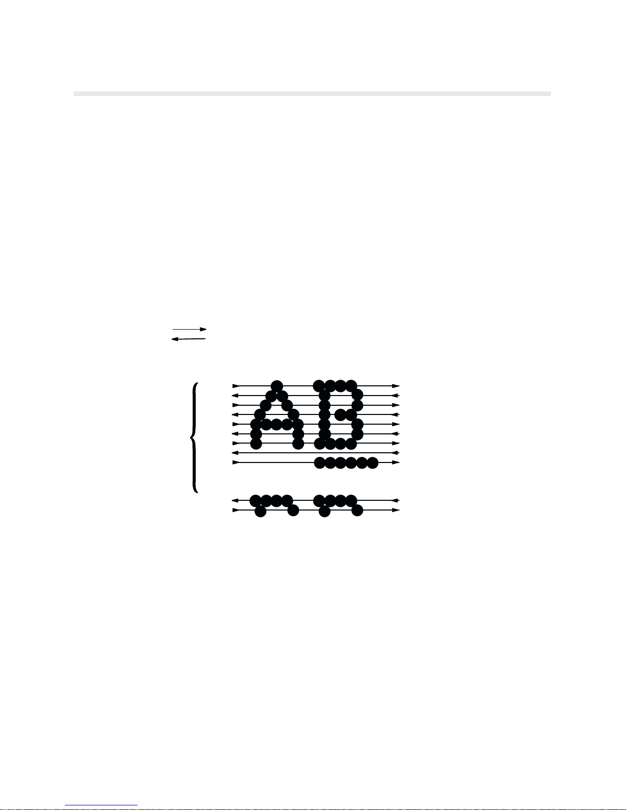
Dot Matrix Line Printing
Unlike single head dot matrix printing, the Printronix P6000L/P6200L Series creates graphics
and characters by printing an entire dot row at one time. As shown in Figure 1-2, dots are
printed in both directions of shuttle travel. In the 400 line per minute printers, the shuttle
sweeps through three tenths (3/10) of an inch. In the 800 line per minute printers, the shuttle
through two tenths (2/10) of an inch. P
sweeps
and
the next row of dots is printed.
During
each sweep of the shuttle, hammers are activated to print dots at selected positions in a
single dot row. When the shuttle reaches the end of a sweep, it reverses direction, paper adĆ
one dot row, and the hammers print the next row of dots.
vances
After
an entire line of characters is printed, hammer
the
first dot row of the next print line. This creates a series of blank rows between lines of char
acters. The number of rows allowed for line separation depends on the line spacing selected.
spacing may be selected from the control panel or the host computer.
Line
INDICATES DIRECTION OF SHUTTLE MOVEMENT
aper is advanced as the
shuttle reverses direction
activity ceases and the paper advances to
Ć
DOT
ROW START
1
2
3
4
ONE
CHARACTER
ROW
5
6
7
8
*
9
**
10
11
12
0
SPACE
1
2
USED FOR LOWERCASE DESCENDER ONLY
*
USED FOR UNDERLINE AND LOWERCASE DESCENDER
**
NOTE: 400 lpm models sweep through three character positions
800 lpm models sweep through two character positions
Figure 1-2. Dot Matrix Line P
rinting
PAPER
ADVANCES
PAPER
FEED
PAPER
ADVANCES
Overview1-4
Page 19
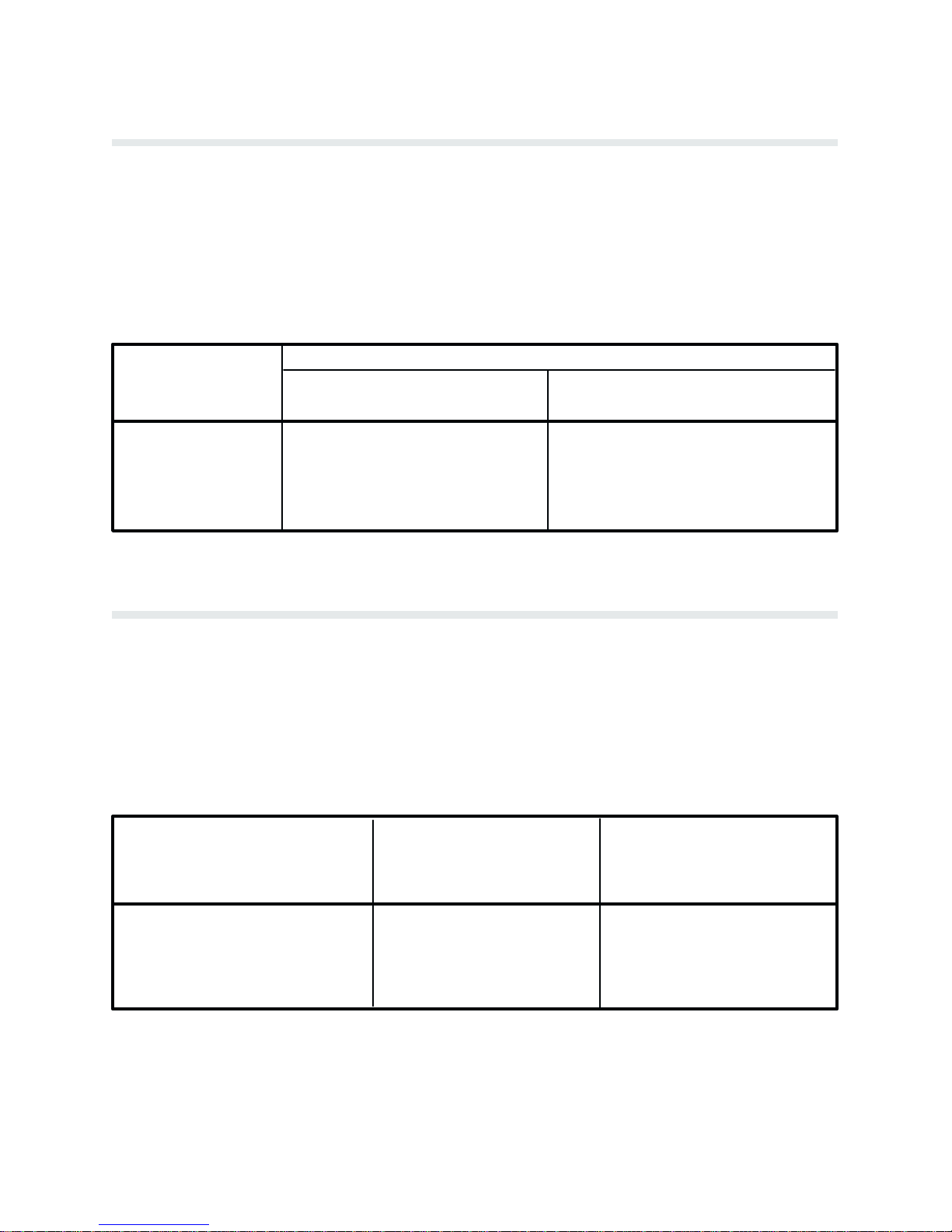
Print Rate
The print rate, in lines per minute (lpm), is a function of the number of dot rows required to
produce the character line regardless of the number of characters in the line. For example,
more dot rows are required to print lowercase characters with descenders and consequently,
those characters are printed at a slower rate. Table 1-1 describes the print rate according to
of character printed and print mode. Complete printing specifications are provided in the
type
Appendix.
PRINT MODE
Table 1-1. Print Rate
PRINT RATE (lpm)
UPPERCASE ONLY UPPER/LOWERCASE
P6040L/P6240L P6080L/P6280L
P6040L/P6240L P6080L/P6280L
Correspondence
Data Processing
High Speed
Plot Rate
As
well as character printing, the printer is capable of dot addressable graphic plotting. Based
on the protocol selected, either P-Series Plot Mode or Serial Matrix Bit Image Graphics is
used; the plot rate specifications apply to both P-Series and Serial Matrix types of graphic
plotting. The plot rate (in inches per minute, ipm) is described in Table 1-2 according to the
dot density (in dots per inch, dpi). Complete plotting specifications are provided in Appendix
C.
DENSITY (dpi)
ă89
300
400
177
600
800
Table 1-2.
P6040L/ P6080L/
P6240L P6280L
Plot Rate
PLOT RATE (ipm)
ă77
240
342
PLOT RATE (ipm)
Unidirectional
P6040L/ P6080L/
P6240L P6280L
154
480
685
60 Horz x 144 Vert (NLQ mode)
60 Horz x 72 Vert (DP mode)
60 Horz x 48 Vert (High Speed) 50 100
16.8
33
33.6
66
8.4
16.6
25 50
16.8
33
1-5Overview
Page 20

Overview1-6
Page 21

Introduction
This
chapter describes basic P6000L/P6200L Series controls and operating procedures. Opera
information and cleaning practices are also provided in the Operator's Guide. R
tion
Installation
P6000L/P6200L Series printers function either online or offline. When online, the printer is
capable
indicates the printer is online and the current print mode. When offline,
pended between the printer and the host computer and the message OFFLINE READY apĆ
pears
of receiving data and control commands from the
on the display. Set the printer offline to perform the following tasks:
n
n
n Run the Self-Test
n
n P
n
n L
n A
n
n A
n A
n Cleaning/R
CHAPTER 2
OPERATION
efer to the
chapter for information on power and site requirements, and printer installation.
host computer. The message display
communication is sus
Select Configuration V
Configure the P
Set T
op-of-Form
erform a Hex Dump
Set Line Spacing
oad P
aper and Ribbon
dvance F
Change P
djust P
dvance P
orms
rint Modes
aper T
ractors
aper
outine Maintenance
alues
rinter
Ć
Ć
P6000L/P6200L Series printers respond to two different command sets or protocol modes:
n
P-Series emulation mode
n
Serial Matrix emulation mode
The
selected protocol determines which programming standard is used by the host computer to
communicate with the printer. Either protocol can be selected as required by the application.
P-Series emulation mode generates characters and graphics by
The
P-Series
control code protocol. The Serial Matrix emulation mode allows printing of charac
ters and graphics utilizing control codes similar to many serial matrix printers used with perĆ
computers. The command protocol is selected
sonal
menu
in
the control panel. R
Series and Serial Matrix protocols and control code definitions.
There are two basic modes of operation: character printing (alphanumeric text) and graphics.
Character
printing is the default mode of operation;
efer to the P
using
Printronix
standard
via the P6000L/P6200L Series application
rogramming chapter for detailed information on P-
graphics, either Serial Matrix compatible
Ć
2-1Operation
Page 22

Bit
Image graphics or P-Series compatible Plot Mode, is programmed on a line-by-line ba
sis.
chapter will discuss the following procedures:
This
n P
ower Switch
n Lock/Unlock F
n
Control P
n P
aper A
n L
oading P
n
Unloading P
n
Setting T
n P
aper Stacking - Floor Cabinet Models
n
Selecting P
n
Setting F
n L
oading the Ribbon
n
Setting Line Spacing
n Hex Code Printout
n P
rinter R
n R
unning the Self-T
unction Switches
anel
djustment Controls
aper
aper
op-of-Form
rint Mode
orms L
ength
eset
est
Ć
or information on the RibbonMinder feature, refer to the RibbonMinder chapter.
F
Power Switch
The printer must be connected to the proper power source, 120/240 V 50/60 Hz, as shown on
the rear panel label. Applying an incorrect power source will damage the printer. Complete
requirement information is provided in the Installation chapter.
power
On floor cabinet models, the printer ac power switch is located on the lower left corner of the
panel as shown in Figure 2-1. On pedestal models, the printer ac power switch is located
rear
on
the lower left side panel
switch
to the ON position.
as shown in Figure 2-2. T
o turn the printer power on, set the power
Operation2-2
Page 23
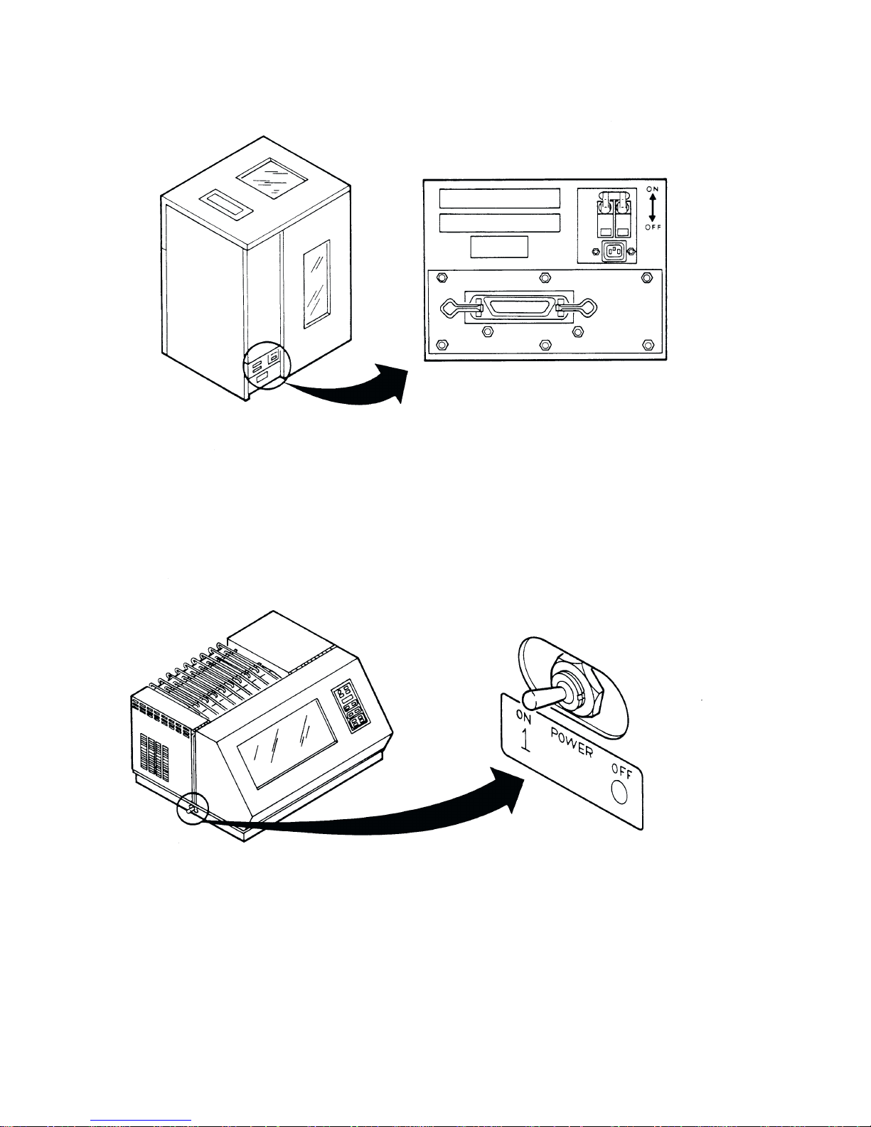
Figure 2-1. P
ower Switch - Floor Cabinet Model
Figure 2-2. P
ower Switch - P
edestal Model
2-3Operation
Page 24

Locking/Unlocking Printer Configuration
To
prevent accidental reconfiguration, the printer configuration (the parameter settings of the
printer) is normally locked. Before any new parameter settings are selected through the use of
the RUN/STOP TEST switch, the printer configuration must be unlocked. Simultaneously
pressing RUN/STOP TEST and CONFIG MENU, while the printer is OFFLINE READY,
alternately unlocks and locks the printer configuration. Resetting the printer or turning the
off and on will also lock the printer configuration.
power
NOTE: While DATA IN BUFFER is present, the printer configuration will remain
Press P
locked.
buffers and remove the DATA IN BUFFER condition.
er's
APER ADV
ANCE
, TOP-OF-FORM, or
Control Panel
The printer control panel contains eleven switches, a power-on indicator, and a 32 character
alphanumeric
ing pages.
Power Indicator - This indicator lights when the ac POWER switch is ON. On floor cabinet
models, the POWER switch is located on the lower left corner of the rear panel. On pedestal
models,
Message Display as shown in Figure 2-3. Each switch is described on the follow
the POWER switch is located on the bottom left side of the printer.
ONLINE to empty the print
Ć
Ć
ON LINE - Press this switch once to place the printer online or offline. The printer must be
online to print. When online, the display will indicate the current print mode and none of the
other control panel switches will function. When offline, the display will indicate OFFLINE
READY and the printer cannot communicate with the host computer. The printer will go ofĆ
automatically when a malfunction occurs and must be offline to change printing format or
fline
configuration.
P
APER ADVANCE -
hold
the switch to advance the paper continuously. This switch functions only when the
is offline.
OF FORM - Press this switch once to advance one forms length (one page) to
TOP
the
next form. This switch functions only when the printer is offline.
Momentarily press this switch to advance the paper one line or press and
printer
the top of
Operation2-4
Page 25
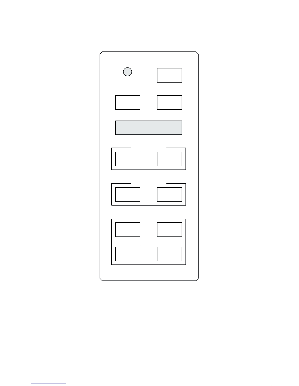
CONTROL PANEL
POWER
ON LINE
PAPER
ADVANCE
MESSAGE
DISPLAY
FORMS SET UP
FORMS
LENGTH
PRINT FORMAT
LINE
SPACING
CONFIG
MENU
TOP OF
FORM
SET
T O F
PRINT
MODE
CONFIG
VALUE
PRINT MODE - Press this switch to display the current print mode. Subsequently pressing
this switch changes the print mode and updates the display through all of the available print
modes listed below. Each print mode has a variety of pitch selections ranging from 10 to 17
characters per inch (cpi). Print mode is a line-by-line attribute; different print modes (and
pitch) can be used for different lines of the form but you cannot mix print modes on one
related
RUN/STOP
TEST
Figure 2-3. Control P
CLEAR
FAULT
anel
2-5Operation
Page 26

individual
must
line. This switch functions
only when the printer is offline. The printer configuration
be unlocked to select a new print mode.
Data P
rocessing (DP) at 10, 12, 13, 15, and 17 cpi.
Correspondence (NLQ) at 10, 12, 13, 15, and 17 cpi.
High Speed at 10, 12, and 13 cpi.
NOTE:
pitch
Print mode control from the host computer will override the
and print attributes can be selected using control codes.
switch setting. Other
Alphanumeric Message Display - The display presents printer status and error condition
messages.
the display
The display has two rows with sixteen characters
indicates the online status and the current print mode (and pitch) selection. When
per row. During normal operation,
offline, the display indicates offline ready.
FORMS
pressing the switch changes the form length and updates the display through all possible
LENG
TH - Press this switch to display the current forms
(page) length. Subsequently
form
length settings from 1.0 to 24.0 inches in 0.5 inch increments. This switch functions only when
printer is offline. The printer configuration
the
NOTE: Forms length control from the host computer will override the switch setting. Us
control codes, forms length in increments other than 0.5 inch can be selected.
ing
SET
TOF
- Press this switch to set the TOF (top-of-form) position. If this switch is pressed
must be unlocked to select a new forms length.
Ć
when the paper is not properly positioned for the required top-of-form, normal operation
and top-of-form function can be affected. Refer to the Setting Top-of-Form section for
complete
instructions. This switch functions only when the printer is offline.
LINE SPACING - Press this switch to display the current line spacing in lines per inch (lpi).
Subsequently
line
spacing settings (6 and 8 lpi). Line spacing is a line-by-line attribute; different line spac
can be used for different lines of the form but you
ing
pressing this switch changes the line spacing and
cannot mix line spacing on one individual
updates the display through all
line. This switch functions only when the printer is offline.The printer configuration does not
have
to be unlocked to change this setting.
Ć
NOTE: Line spacing control from the host computer will override the switch setting.
Control
codes from the host computer can select line spacing other than the 6 or 8 lpi.
CONFIGURATION MENU - Configuration Menu (CONFIG MENU) is used to display/seĆ
lect configuration parameter main menus and certain submenus. Pressing CONFIG MENU
simultaneously
with RUN/STOP TEST alternately locks and unlocks the printer configuration
(the printer must be offline). Repeatedly pressing CONFIG MENU displays the following
menus:
D Ribbon Life
D
Character Set
D
Application Compatibility
D P
aper F
ormat
D
Host Interface
D L
oad P
arameters
D Save Parameters
Operation2-6
Page 27

D Diagnostics
After the required menu is displayed, individual parameters
VA L
UE switch as shown on the Control P
anel Switch F
are displayed using the CONFIG
unction Diagram in the Configuration
chapter.
CONFIGURATION
configuration parameters and the current value from within the main menus.
vidual
NOTE:
allows
Alternately and/or
the display of the configuration parameters as shown on the Control P
VALUE - Press Configuration V
repeatedly pressing CONFIG MENU and CONFIG V
alue (CONFIG VALUE) to display indi
anel Switch
Function Diagram in the Configuration chapter. The CONFIG MENU and CONFIG
VA LU E
menu,
RUN/STOP TEST -
n Press RUN/STOP TEST simultaneously with CONFIG MENU to alternately unĆ
n Press RUN/STOP TEST to select a configuration parameter, forms length, or print
switches when pressed simultaneously
forms length, and print mode selections.
The RUN/STOP TEST switch performs the following functions:
and lock the printer configuration..
lock
An asterisk (*) will appear to the right of the value to indicate that it has been
mode.
step backward through the configuration
selected.
n Press
n If a self-test is selected and shown on the display, press RUN/STOP TEST to start
RUN/STOP TEST simultaneously with CLEAR F
AUL
T to reset the printer.
the test and press it again to stop the test.
n If the CONFIGURATION PRINTOUT message is selected and shown on the disĆ
press RUN/STOP TEST to print a list of the current configuration. P
play,
STOP
TEST again to return to OFFLINE READ
Y.
Ć
ALUE
ress RUN/
CLEAR FAULT - Press this switch to reset the printer after a fault condition has been corĆ
rected. Fault conditions are indicated on the display. After pressing CLEAR FAULT the disĆ
will indicate the printer is offline if the fault was corrected.
play
In addition, the CLEAR F
n P
ress CLEAR F
n Press
menu
CLEAR F
parameter
AUL
AUL
AUL
selection or to offline. R
Diagram in the Configuration chapter.
Paper Adjustment Controls
The printer paper loading controls for the floor cabinet model are shown in Figure 2-4. The
printer paper loading controls for the pedestal model are shown in Figure 2-5. The controls
the F
are
Adjustment
trol
orms Thickness A
Knob (C), and the paper tractors (D). The P
panel is also used during the paper loading procedure.
djustment L
T switch performs two special functions:
T simultaneously with RUN/STOP TEST to reset the printer.
T when one of the parameter values is displayed to move up one
ever (A),
efer to the Control P
the V
ertical P
osition Knob (B), the Horizontal
APER ADVANCE switch on the con
anel Switch F
unction
Ć
2-7Operation
Page 28

Figure 2-4. P
aper Adjustment Controls - Floor Cabinet Model
Operation2-8
Page 29
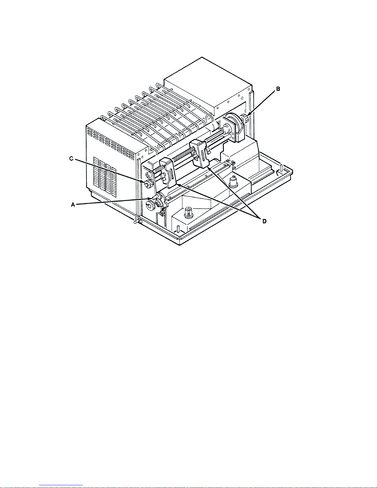
Figure 2-5. P
aper Adjustment Controls - P
edestal Model
Forms Thickness Adjustment Lever - The Forms Thickness Adjustment Lever, shown in
Figure 2-6,
closes
controls
the platen to adjust
the platen gap. R
aising the lever opens the platen and lowering the lever
for various paper thicknesses. The scale indicates approximate posi
tioning to correspond with paper thickness (1 to 6 part forms). Generally, set the lever for a
slight friction on the paper as it moves past the hammer bank. If the F
ment Lever is
of
vertical lines (called poor phasing). When fully
and ribbon replacement; a platen open message is shown on the display. After lowering the
ing
set incorrectly, the print hammer flight timing can be upset, resulting in waviness
raised, the platen is open to allow paper load
orms Thickness A
djustĆ
lever to the appropriate operating position, press CLEAR FAULT on the Control Panel to
the platen open condition.
clear
Ć
Ć
2-9Operation
Page 30
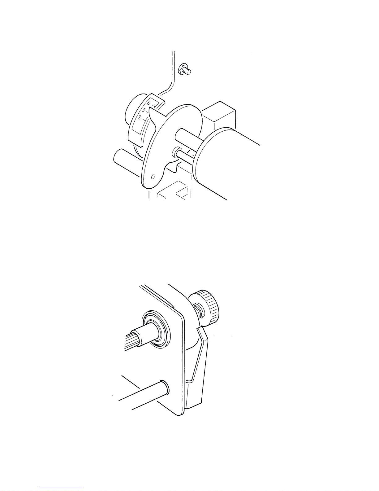
Figure 2-6. Forms Thickness Adjustment Lever
Vertical Position Knob - The Vertical Position Knob, shown in Figure 2-7, moves the paper
or down. The platen must be open (F
up
this
control.
orms Thickness A
djustment L
ever fully raised) to use
Figure 2-7. V
ertical P
osition Knob
Operation2-10
Page 31

Horizontal Adjustment Knob - The Horizontal Adjustment Knob, shown in Figure 2-8,
shifts the paper left or right up to approximately !/3 inch. This control is used to make fine
adjustments
to the left margin. Once adjusted, further adjustments are usually not required.
Figure 2-8. Horizontal Adjustment Knob
Tractors
- The paper tractors feed the paper through the printer. The position of the left trac
tor, shown in Figure 2-9, establishes the left paper margin. Normally, the left tractor is posiĆ
for the left print margin (first character position) to align with character column 1 on the
tioned
paper scale (on top of the ribbon deck cover). Once properly positioned, further adjustments
are not required unless a change is made to the left print margin. Margins can also be estabĆ
by control codes from the host computer. R
lished
tractor
position is adjusted to compensate for various paper widths. Both tractors are locked in
efer to the P
rogramming chapter. The right
position during normal operation and must be unlocked to make any position adjustment. To
unlock the tractor, simply raise or lower the tractor lock to the center position and slide the
as necessary. If the tractor has screw-type locks, simply rotate the knobs to lock/unlock
tractor
the
tractor. Once in position, be sure to lock the tractor again.
Ć
2-11Operation
Page 32

Loading Paper
P6000L/P6200L Series printers use standard fanfold paper from 3 to 16 inches wide and 15 to
lb bond (0.025 inches thick maximum). T
100
to Figure 2-10.
1.
Place the printer offline and raise the top cover.
2. F
ully raise the F
3.
Open both tractor gates (B) by swinging them out.
4. On floor cabinet models, open the front cover and feed the paper up through the paper
(C) from below.
slot
the pedestal or table from below. On both models, push the paper up until it appears
above
5. Load the paper on the tractor sprockets (E); close the tractor gates (B). If necessary to
the right tractor to remove paper slack or to adjust for various paper widths, release
slide
the right tractor lock (F) by raising or lowering it to the center; slide the tractor into
After positioning the tractor, lock it in place.
tion.
Figure 2-9. Left P
orms Thickness A
On pedestal models, feed the paper up through the paper slot (C) in
the ribbon mask (D). If the paper snags, fold the top edge down before feeding.
djustment L
aper T
ractor
o load paper, perform the following steps and refer
ever (A).
posi
Ć
NOTE: The left tractor should remain locked in alignment with the number 1" on the
paper scale to set the left margin with the first character space.
Operation2-12
Page 33

6. Press TOP OF FORM or PAPER ADVANCE to further advance paper into the paper
stacking area. V
erify unobstructed paper feeding.
7. Set
8. P
9.
10.
11. On
the F
parts).
If closed too tightly, the shuttle may smear or tear the paper.
ress CLEAR F
Set the top-of-form as described in the Setting T
Close the printer cover.
floor cabinet models, perform the P
properly.
ing
Unloading Paper
1. Place
2. Tear off the paper below the paper guide. On pedestal model printers, this will be at the
3. F
4.
5. Gently
the printer offline.
bottom
Open both tractor gates and remove the paper from the tractor sprockets.
sprocket
of the printer.
ully raise the F
pull the paper up through the paper
holes catch on the ribbon mask.
orms Thickness A
AUL
T and place the printer online.
orms Thickness A
djustment L
djustment L
ever (A) to approximate the paper thickness (1 to 6
op-of-F
aper Stacking instructions to start the paper stack
ever.
slot. Be careful not to let paper perforations or
orm procedure.
Ć
2-13Operation
Page 34

Figure 2-10. Loading P
aper
Operation2-14
Page 35

Setting Top-of-Form
Top-of-form determines where the first line of print will appear and should be set when paĆ
is loaded. Generally, set the first line of print about one-half inch below the paper perfora
per
or where application requirements dictate.
tion
After
the top-of-form is set, the paper can be advanced to the
the
TOP OF FORM switch. Unless specifically
11-inch length paper is used. For alternate length forms, refer to the Setting Forms Length
section.
the following procedure to set the top-of-form.
Use
1.
Place the printer offline.
Ć
top of the next form by pressing
altered, P6000L/P6200L Series printers assume
2. Fully
3. Set the Forms Thickness Adjustment Lever to approximate the paper thickness (1 to 6
4. P
5. Press SET TOF.
6.
raise the F
to
be printed at
Figure 2-11.
If closed too tightly, the shuttle may smear or tear the paper.
parts).
ress Clear F
NOTE: Pressing SET TOF at any other time will reset the top-of-form position.
Place the printer online.
orms Thickness A
the top of the black TOP-FORM mark on the left tractor gate as shown in
ault to clear the PLA
djustment L
TEN OPEN condition.
ever (A) to position the
top of the first line
Figure 2-11. Setting Top-Of-Form
2-15Operation
Page 36

Paper Stacking - Floor Cabinet Models
The floor cabinet model is capable of stacking up to one complete box of standard computer
paper when the paper is properly loaded. After loading the paper, perform the following inĆ
structions.
1. Open
2.
the rear cabinet door to access the paper stacking area.
NOTE: Steps 2 and 3 pertain to installation of the two paper stacking fences, the front
between the paper stack and the paper supply and the rear fence on the rear cabinet
fence
door. If these fences have already been installed, continue with the paper stacking inĆ
structions at step 4.
If not previously installed, install the front paper fence in the bracket as close as
to the paper stacking area as shown in Figure 2-12. The bracket is located in the upper
portion of the printer paper stacking area near the outer edges. The fence must be inĆ
stalled in the same bracket position on each side to maintain a straight vertical orientaĆ
tion.
possible
Figure 2-12.
3. If not previously installed, install the rear paper fence on the inside of the rear cabinet
door placing the fence in the brackets at each upper edge of the door and in the bracket
centered
on the lower edge of the door as shown in Figure 2-13.
Front P
aper F
ence Installation - Floor Cabinet Models
Operation2-16
Page 37

Figure 2-13. R
ear P
aper F
ence Installation - Floor Cabinet Models
4. Install the paper stacking tent into the paper stacking area with the far edge of the tent
the front paper fence as shown in Figure 2-14.
against
5. Align
the outer edges of the tent with the outer edges of the paper supply as seen through
the
printer cabinet.
6. Advance
the paper until a few sheets begin to stack
on the tent as shown in Figure 2-15.
2-17Operation
Page 38

Figure 2-14. Paper T
ent Installation - Floor Cabinet Models
Figure 2-15. P
aper Stacking - Floor Cabinet Models
Operation2-18
Page 39

7. V
erify the following and make any necessary adjustments.
a.
The paper stack is centered on the tent
b.
The paper perforation folds are folding in their natural prefolded direction.
c. The paper is following a straight path down to the tent in alignment with the outer
edges.
.
d. The
8. R
un the printer and let approximately 15 to 20 sheets of paper stack.
9. Again verify the items listed in step 7. Any adjustments to the paper stack can be made
while
mately
NOTE: If the paper is not stacking properly, check the following items in addition to
those
paper is against the front paper fence as it rests centered on the tent.
the printer is running. If an adjustment is made, again check the stack after approxi
15 to 20 sheets have been processed.
listed in step 7.
1. If
printing occurs across the paper perforations, the paper will not stack cor
Adjust the Skip Over P
rectly.
printing across the paper perforations.
2. If the paper path is too close to either side panel, paper stacking can be disĆ
Adjust the paper path toward the center of the printer
rupted.
side
panels.
3. The
front paper fence may be incorrectly positioned. R
fence into one of the other bracket locations.
per
Selecting Print Mode
erforation configuration parameter to eliminate
, away from the
eposition the front
pa
Ć
Ć
Ć
Characters and symbols are printed based on the print mode selected. During normal operaĆ
tion, the message display indicates the printer is
F
or example,
ON LINE
DP A
T 10 CPI *
indicates
mode,
1.
2. Simultaneously
3. Press
4. R
5. P
6. P
the Data P
perform the following instructions.
Place the printer offline.
figuration.
PRINT MODE; the display will show the current print mode.
epeatedly press PRINT MODE until the required print mode is displayed.
ress RUN/STOP TEST to select the displayed print mode.
ress CLEAR F
rocessing print mode at 10
press RUN/STOP TEST and CONFIG MENU to unlock the printer con
AUL
T to return to OFFLINE READ
online and the print mode currently selected.
characters per inch is selected. T
Y.
o select a print
Ć
2-19Operation
Page 40

7. Simultaneously press RUN/STOP TEST and CONFIG MENU again to lock the
configuration.
Additional printing capabilities and character attributes can be used by sending the appropriĆ
control codes to the printer from the host
ate
P
rint mode control from the host computer will override the control panel setting.
ter.
Loading the Ribbon
Each
printer is shipped with an OCR (extra dark) ribbon. The ribbon should be replaced when
the
print contrast is too light or approximately after
To
replace the ribbon, perform the following steps and refer to Figure 2-16.
1.
Place the printer offline and raise the top cover.
2. F
ully raise the F
3. Unlatch each ribbon spool (B) and carefully lift them off the hubs (C). Raise the ribbon
of the ribbon path. P
out
4.
Place each new ribbon spool (B) on a hub (C) with the ribbon to the outside. The ribbon
rewinds automatically; either ribbon spool can be loaded on either hub.
Place the printer on line.
orms Thickness A
roperly discard the used ribbon.
djustment L
computer as described in the P
each box of standard size computer paper.
ever (A) to open the platen.
rogramming chap
printer
Ć
5. P
ress the spools down until the latch (D) snaps in place.
6. Thread
the
tallic
NOTE: The ribbon must not be twisted in the ribbon path. A twisted ribbon can lower
print
7. Lower
8. Press CLEAR FAUL
9.
Close the top cover and place the printer online.
the ribbon around the ribbon guides (E) and through the ribbon path as shown in
diagram (F) on the ribbon deck cover. The ribbon must pass between the two thin me
strips called the hammer bank cover (G) and the ribbon mask (H).
quality
, shorten ribbon life, or cause a paper jam.
the F
orms Thickness A
T on the control panel to clear the platen open condition.
djustment L
ever (A) to the appropriate operating
Ć
position.
Operation2-20
Page 41

Setting Forms Length
P6000L/P6200L Series printers may use continuous, tractor-fed paper with the forms length
in inches (between 1.0 and 24.0) or lines (between 1
set
the forms length in lines at 6 or 8 lpi does not change the line spacing. The printer has been
preset for standard 11-inch length paper. Therefore, when using alternate length paper, the
top-of-form setting and the forms length setting must be changed to match the alternate
length. T
1.
o set the forms length:
Place the printer offline.
Figure 2-16. Ribbon Replacement
and 192 at 6 or 8 lines per inch). Setting
2. Simultaneously
figuration.
3. Press FORMS LENGTH; the display will show the current FORMS LENGTH SET IN
INCHES.
4. Continuously
tions: FORMS LENGTH SET IN 6 LPI LINES, FORMS LENGTH SET IN 8 LPI
LINES, and FORMS LENGTH SET IN INCHES. Choose the appropriate setting, perĆ
the corresponding instructions, and then save the selected forms length.
form
To set the forms length in inches:
5. Press FORMS LENGTH until FORMS LENG
press RUN/STOP TEST and CONFIG MENU to unlock the printer con
pressing FORMS
LENG
TH will step the display through the following op
TH SET IN INCHES is displayed.
Ć
Ć
2-21Operation
Page 42

6. Press CONFIG VAL
UE to dislay the current forms length in inches.
7. Continue
taneously press CONFIG VALUE and CONFIG MENU to decrement the forms length
0.5 inch. After the appropriate value is displayed, save it as described below.
by
To set the forms length in lines:
8. Press
is
displayed.
9. Press CONFIG VAL
10. Continue pressing CONFIG VAL
neously
1
line. After the appropriate value is displayed, save it as described below.
To save the displayed forms length:
ress RUN/STOP TEST to select the displayed forms length.
11. P
12. P
ress CLEAR F
13. Simultaneously press RUN/STOP TEST and CONFIG MENU to lock the printer conĆ
figuration.
14. Set
pressing CONFIG VALUE to
FORMS LENG
press CONFIG VALUE and CONFIG MENU to decrement the forms length by
the top-of-form using the Setting T
TH until
UE to dislay the current forms length in lines.
AUL
T to return to OFFLINE READ
FORMS LENG
increment the forms length by 0.5 inch or simul
TH SET IN 6 LPI LINES or 8 LPI LINES
UE to increment the forms length by 1 line or simulta
Y.
op-of-F
orm instructions.
Ć
Ć
Forms length in inches can also be set by control code from the host computer. Forms length
from the host computer will override the control panel setting.
control
Setting Line Spacing
P6000L/P6200L
control panel using the LINE SPACING switch. To select the line spacing from the control
perform the following steps.
panel,
1.
Place the printer offline.
2. P
ress LINE SPACING; the display will show the current line spacing.
3. P
ress LINE SPACING again to display and select the alternate line spacing.
4. P
ress CLEAR F
Line
spacing can also be selected by sending line spacing control codes from the host computer.
Using control codes, line spacing
host
computer will override the control panel setting.
Series printers can be set for a line spacing of 6 or 8 lines per inch (lpi) from the
AUL
T to return to OFFLINE READ
other than 6 or 8 lpi is available. Line spacing control from the
Y. Place the printer on line.
Operation2-22
Page 43

Hex Code Printout
The
hex code printout
the host with their corresponding two-digit hex code. Nonprintable characters are indicated
a period symbol. A p" before the hex code
with
a blank space before the hex code indicates an inactive PI line. To print the data stream sent
from the host computer in hex code with ASCII character equivalents, perform the following
steps.
(called a hex dump) provides a listing of A
indicates an active P
SCII character data sent from
aper Instruction (PI) line;
1. Place
2. R
3. Press CONFIG VALUE; CONFIGURA
4. P
5. P
6. P
7.
8. Press
9.
the printer offline.
epeatedly press CONFIG MENU until the DIA
TION PRINTOUT will be displayed.
ress CONFIG MENU; PRINT D
ress RUN/STOP TEST
ress ONLINE. The display will indicate ONLINE HEX DUMP
Send the data from the host; the hex dump will print.
ONLINE again to stop the
Repeatedly
Place the printer online.
press CLEAR F
; the display will be OFFLINE HEX DUMP
ATA
STREAM IN HEX CODE will be displayed.
hex dump. P
AUL
T to return to OFFLINE READ
GNOSTICS message is displayed.
ress RUN/STOP TEST to exit HEX DUMP
.
.
.
Y.
2-23Operation
Page 44

Printer Reset
The printer can be reset to the power-up configuration values whenever necessary. To reset
the printer, simply press CLEAR FAULT and RUN/STOP TEST simultaneously. The proceĆ
resets the printer to the configuration values last saved, not factory default values.
dure
Running the Self-Test
P6000L/P6200L Series printers include various self-test functions. Use the self-test as
needed
T
1.
2. R
to determine if the printer is functioning normally.
o run the self-tests:
Place the printer offline.
epeatedly press CONFIG MENU until DIA
GNOSTICS is displayed.
3. Press CONFIG VALUE; CONFIGURA
4. Repeatedly press CONFIG MENU until either PRINTER TEST 8 INCH WIDTH or
PRINTER
5. Repeatedly press CONFIG VALUE until the appropriate test is displayed. T
shift
6. Press
stop
Examine the print quality. The characters should be solidly formed and aligned. If not, there
be a problem with the printer.
may
7. R
epeatedly press CLEAR F
8.
Place the printer online.
TEST FULL WIDTH is displayed.
recycle, all Es, and others.
RUN/STOP TEST to begin the selected self-test; press RUN/STOP TEST again
the test.
AUL
T to place the printer offline.
TION PRINTOUT will be displayed.
ests include
to
Operation2-24
Page 45

Introduction
CHAPTER 3
CONFIGURATION
Configuration
to
commands sent from the host computer. Most all the configuration parameters are selected
from the control panel as shown on the Control Panel Switch Function Diagrams. A few conĆ
figuration
the
Hardware Jumper Configuration section.
Before reconfiguring any printer function, be sure to read this entire chapter. The following
information
n Lock/Unlock P
n
n
n Set/Save/Load Configuration Values
n Default Configuration Values
n
n
n
refers to a set of operating parameters that define how the printer will respond
parameters are hardware selectable by jumpers on the L
is presented:
rinter Configuration
Configuration Menus
Configuration P
Configuration P
Hardware Jumper Configuration
Control P
rocedure
rintout
anel Switch F
unction Diagram
Locking/Unlocking Printer Configuration
As previously described in the Operation chapter, the printer configuration is locked to preĆ
vent accidental or unintentional reconfiguration. Pressing the RUN/STOP TEST and CONĆ
FIG MENU switches simultaneously will alternately unlock or lock the printer configuration.
P
rinter configuration must be unlocked to reconfigure the printer from the control
The
ogic C board as described in
panel.
NOTE: While DATA IN BUFFER is present, the printer configuration will remain
Press P
locked.
buffers and remove the DATA IN BUFFER condition.
er's
APER ADV
Configuration Menus
The CONFIG MENU switch accesses and displays the various control panel selectable conĆ
figuration menus. The individual parameter values within each
edly pressing
message display:
D
the CONFIG VALUE switch. The following configuration menus appear on the
Ribbon Life
ANCE
, TOP-OF-FORM, or
ONLINE to empty the print
menu are displayed by repeat
Ć
Ć
3-1Configuration
Page 46

D Character
D
Application Compatibility
D P
aper F
D
Host Interface
D L
oad P
D Save Parameters
D Diagnostics
F
rom these menus, the related configuration parameter values can be displayed and selected.
Set
ormat
arameters
Configuration Procedure
Most configuration options can be selected from the control panel. The few hardware selecĆ
table configuration options are described in the Hardware Jumper Configuration section. To
or modify the configuration
verify
(OFFLINE
fline
configuration
Basic configuration procedure requires alternately pressing the CONFIG MENU and CONĆ
V
ALUE
FIG
tration of the configuration menus are described in the Control Panel Switch Function
Diagram section of this chapter. Thoroughly review the diagram to understand the
tion menu hierarchy and the control panel switches necessary to access and display individual
and parameter values.
menus
READ
Y), and the printer configuration unlocked to select parameters in the
menus.
switches to arrive at the desired parameter. The use of these switches and an illus
from the control panel, the printer must be powered up, of
configura
Ć
Ć
Ć
The
following general procedure can be used to reconfigure the printer from the control panel
as necessary to meet application requirements. Detailed descriptions are provided following
general procedure.
the
1. Simultaneously
press RUN/STOP TEST and CONFIG MENU to unlock the printer con
figuration.
2. Obtain a current configuration listing as described in the Configuration Printout section
this chapter.
of
3. Determine
the parameter values that must be changed to meet requirements. R
efer to the
Control Panel Switch Function Diagram for an illustration of the parameter values and
procedure required to select and display the values.
the
4.
Select and display the required value(s).
5.
Enter the value(s) by pressing the RUN/STOP TEST switch.
6. Save the value(s) as the current default (if desired) as described in the Set/Save/Load
Configuration V
7. Simultaneously press RUN/STOP TEST and CONFIG MENU again to lock the
alue section of this chapter.
printer
configuration.
8. Place
the printer online. The selected values are effective.
Ć
Configuration3-2
Page 47

Set/Save/Load Configuration Values
Configuration
power-up default configuration. In addition, current power-up default values
(restored)
values can be stored for temporary use or saved for more permanent use as the
can be loaded
for use as needed.
Set Values
Any
configuration value can be changed as needed to meet application requirements. In order
to change a configuration parameter, the printer configuration must be unlocked. Select the
value of the configuration parameter and press the RUN/STOP TEST
new
(*)
will appear to the right of the value to indicate its selection.
NOTE: This type of change is only temporary. To permanently change a configuration
parameter, refer to the Save V
For example, to temporarily change the forms length parameter to 14.0 inches, unlock the
configuration and
printer
STOP TEST switch to enter the value. 14.0 inches will now be
ter.
alues stored in this way are replaced by the power-up default (saved) values when the printer
V
power
is turned off
it can be stored temporarily. If the value is required for more permanent repeated use,
cation,
it should be saved as a power-up default.
select and display a forms length value of 14.0 inches. P
and on. If a particular value is only required for a short term, limited appli
alues section of this chapter
.
used
as the forms length parame
switch. An asterisk
ress the RUN/
Ć
Ć
Saved Values
Saved configuration values are the power-up default values. These are the parameters effecĆ
tive when the power is turned on. Until another value set is saved, the Printronix default conĆ
figuration values are effective at the initial power-up after receiving the printer from the
factory.
Control Panel Switch Function Diagram for an illustration of the control panel switches reĆ
quired
1. Unlock the printer configuration by simultaneously pressing the RUN/STOP TEST and
2. Select
3.
The following general procedure can be used to save configuration values. Refer to the
to select and display the parameter menus and values.
CONFIG
to
enter the change(s).
NOTE: Changing the Printer Compatibility under the Application Compatibility menu
affects
others. It also sets the current paper position as the top of form. Consequently, if the
Printer Compatibility configuration parameter is changed, it must be changed before
changing
patibility
Select and display S
MENU switches.
the value(s) required
other parameter value choices, automatically disabling some values and resetting
any other parameter
value may be cancelled and not saved with the value set.
AVE PARAMETERS.
as the power-up defaults using the RUN/STOP TEST switch
values. V
alues changed prior to changing the Printer Com
Ć
3-3Configuration
Page 48

4. Press
5. P
6. Lock the printer configuration by simultaneously pressing the RUN/STOP TEST and
The
is
important to remember that all currently selected values are saved, not just the specific value
most recently changed. Note also that values changed by control code sequences will also be
saved.
are subsequently saved, the print mode change is also saved. However, horizontal tab posiĆ
tions, margin settings, and character attributes such as bold, double high, etc. that can be
changed
tion value set.
RUN/STOP TEST
value
set.
ress CLEAR F
CONFIG
saved
values remain effective until specifically changed by storing or saving other values. It
F
or example, if the print mode is changed by control code and the configuration values
by control code but are not reflected on the display are not saved with the configura
AUL
MENU switches, and place the printer online.
. All currently selected values are saved as the power-up default
T once to return to OFFLINE READ
Y.
Load Values
The
current power-up default configuration value set can be loaded (restored) as needed. If,
for
example, a number of configuration values were
complete power-up default set can be restored. This provides a convenient method of resetĆ
the printer's
ting
to
load (restore) the power-up default values.
configuration to known values. The following general procedure can be used
changed and stored for temporary use, the
Ć
1. Unlock the printer configuration by simultaneously pressing the RUN/STOP TEST and
CONFIG
2.
Select and display LO
3. Repeatedly press CONFIG VALUE until the LOAD DEFAULT PARAMETERS mesĆ
sage
4. Press
5. Press CLEAR FAUL
6. L
ock the printer configuration and place the printer online.
MENU switches.
is displayed.
RUN/STOP TEST
T once to return to OFFLINE READ
AD P
ARAMETERS.
. The current power-up default values are restored and in effect.
Y.
Configuration3-4
Page 49

Default Configuration Values
The
printer comes from the factory with a set of
in Table 3-1. These values are operational when the printer is received from the factory. New
values
can be selected and stored or saved as necessary for each application.
T
able 3-1. P
Printronix default configuration values as listed
rintronix Default Configuration Values
CONFIGURATION DEFAULT
PARAMETER VALUE
Forms Length
Print Mode
Line Spacing
Character Set
Printer Protocol
Buffer Size
Automatic Line Feed
Define CR Code
Define LF Code
Uppercase/Lowercase
Special Function Character
VFU Select
Paper Motion Detector
Power On State
Mod Plot
Unidirectional Printing Disable
Perforation Skip
Paper Fault Stop
Data Line 8
PI Line
Fast Busy Enable
11.0 Inches
DP 10 cpi
6 lpi
ASCII
P-Series
2048 characters
After Full Line
CR = CR
LF = CR + LF
Upper and Lower
Disable
EVFU
Enable
Online
Disable
Disable
End of Paper
Enable
Disable
CONFIGURATION DEFAULT
PARAMETER VALUE
Job Rate 350
Ribbon Size
When Worn Action
RibbonMinder Action
Printer Select Disable
Paper Advance Switch
Slew Relative
Host Interface
Data Polarity
Response Polarity
Data Protocol
Data Rate
Word Length
Stop Bit
Parity None
Bit 8 Function Font
CD and DSR
CTS and DSR
Data Term Ready
Request to Send Online and BNF
Reverse Channel Online and BNF
60
Stop Printer
Disable
Print + Paper Advance
1 to 16
Centronics
Standard
Standard
XON/XOFF
9600
8 Bits
One
Disable
Disable
Online and BNF
3-5Configuration
Page 50

Configuration Printout
The
configuration printout lists all of the currently selected configuration
sample
configuration printout is shown in Figure 3-1.
The following general procedure can be used to obtain a configuration printout. Refer to the
Control Panel Switch Function Diagram for an illustration of the switches required to select
display the parameter menus and values.
and
1. V
erify the POWER indicator is lit and the printer is off line.
2. R
epeatedly press CONFIG MENU until DIA
parameter values. A
GNOSTICS is displayed.
3. Press
4. Press RUN/STOP TEST
5. P
CONFIG VALUE; select and display the CONFIGURATION PRINTOUT menu.
. The configuration printout will be produced.
ress RUN/STOP TEST again to return to OFFLINE READ
Y.
Configuration3-6
Page 51

Figure 3-1. Sample Configuration P
rintout
3-7Configuration
Page 52

Hardware Jumper Configuration
Jumpers
ers are installed for normal operation at the factory. However, certain applications may reĆ
quire a modification to the jumper configuration. To change any of these configuration
jumpers,
To access the Logic C PCBA in floor cabinet model printers, the right side panel must be reĆ
moved
the L
on the L
the C3 logic board must
and the
ogic C PCBA for both the floor cabinet and pedestal models.
of these hardware changes require attention to detail on the
Any
prevent damage. Some configurations require cutting an etch on the PCBA and sol
dering. These changes should only be performed by a trained technician.
ogic C board are used to
be removed. T
card cage lowered. The following procedures provide instructions on accessing
- WARNING -
select a few configuration parameters. These jump
able 3-2 describes the jumper configurations.
PCBA assembly to
Ć
Side Panel Removal - Floor Cabinet Model
To
remove the right side panel, perform the following instructions and refer to Figure 3-2.
1. T
urn the printer off and disconnect the ac power cord.
2. R
aise the printer cover.
3.
Disconnect the two ground wire connectors (A) from the corners of the side panel.
Ć
4. Loosen the side panel release screw (B) with the Phillips head screwdriver. Do not reĆ
the screw; simply loosen it enough to slide in the notched cutout on the frame.
move
5. Using both hands, lift the side panel up and out from the bottom edge. The panel fits
on four mounting studs (C). First time removal of the side panel may require extra
snugly
pressure to unseat the studs from the panel keyholes (D). The card cage can now be acĆ
cessed.
Configuration3-8
Page 53

Figure 3-2.
Side P
anel R
emoval - Floor Cabinet Model
Removing the PCBA - Floor Cabinet Model
After removing the side panel, the card cage can be accessed. To remove the Logic C PCBA
the card cage, perform the following instructions and refer to Figure 3-3.
from
1. To
2. L
3.
4. Snap out the top and bottom ejector levers (E) to release the PCBA from the edge conĆ
5. Gently
6. Make or verify the required jumper configuration change(s). See Table 3-2 on page
lower
the card cage (A), loosen but do not remove the release wing nut (B) on the right
side
of the card cage and gently pull the front edge of the cage down.
ocate the L
Cut the tie wrap restraints (D) if present.
nector.
3-13.
ogic C PCBA (C); the names of the PCBAs are printed on the card cage.
slide the PCBA out of the card cage.
3-9Configuration
Page 54

7. Align
the PCBA with its slot and gently slide it back into the card cage.
8. Press
the ejection levers (E) back into position to secure the
PCBA into the edge connec
tor. If the PCBA does not go into position with only moderate force, remove the PCBA
realign it in its slot.
and
- WARNING -
Forcing the PCBA back into position can damage components or break the PCBA.
Never
force the PCBA into position; always realign and reinstall
be replaced with only moderate force.
not
9. R
aise the card cage (A); secure it by tightening the release wing nut (B).
10. R
eplace the side panel on the mounting studs.
11. T
ighten the side panel release screw.
12.
Connect the ground wires to the corners of the side panel.
13.
Close the printer cover.
14.
Connect the ac power source.
the PCBA if it can
Ć
Ć
Figure 3-3. PCBA R
emoval - Floor Cabinet Model P
rinter
Configuration3-10
Page 55

Logic C PCBA Removal and Replacement - Pedestal Model Printer
Perform
PCBA.
1. Turn
2. Turn the two captive screws (A) at the top of the rear panel to unlock it. Lower the rear
3. Swing
4. L
5.
6. Snap out the top and bottom ejector levers (E) to release the PCBA from the edge conĆ
7. Gently
8.
9.
10. Press
the following instructions and refer to Figure 3-4 to remove and replace the L
the printer off and disconnect the ac power cord.
panel.
the card cage (B) out from the back of the printer.
ocate the L
Cut the tie wrap restraints (D) if present.
nector.
Make or verify the required jumper configuration change(s). R
Align the PCBA with its slot and gently slide it back into the card cage.
the ejection levers (E) back into position to secure the
tor. If the PCBA does not go into position with only moderate force, remove the PCBA
realign it in its slot.
and
ogic C PCBA (C); the names of the PCBAs are printed on the card cage.
slide the PCBA out of the card cage.
efer to Table 4-2.
PCBA into the edge connec
ogic
C
Ć
- WARNING -
Forcing
the
stall
11.
Swing the card cage (B) back into the printer.
NOTE
levers.
12. R
13. R
the PCBA back into position can cause damage to the components or break
PCBA
. Never force the PCBA back into position; always try to realign and rein
the PCBA if a large amount of pressure must be exerted.
: It is not necessary to replace the tie wrap restraints on the ejector
aise the rear panel and secure it with the two screws.
econnect the ac power cord and turn the printer on.
Ć
3-11Configuration
Page 56

Figure 3-4. PCBA R
emoval - P
edestal Model P
rinter
Configuration3-12
Page 57

T
able 3-2. Hardware Jumper Configuration
JUMPER LOCATION DESCRIPTION
E3-E6 NTXCLK Input - Serial Interface Transmit Clock *
E4-E7 NRXCLK Input - Serial Interface Receive Clock *
E5-E8 NEXTCLK Input - Serial Interface External Clock *
E6-E9 Clock to TC Input - Serial Interface *
E7-E10 Clock to RC Input - Serial Interface *
E8-E11 Timer C Output to Clock - Serial Interface *
E14-E15 Dataproducts Strobe Polarity In = Inverted
E18-E19 P6X80 Select In = P6X80
Out = P6X40
E20-E21 P6X80 NRESYNC Timer Must be IN for P6X80
E32-E33 P6X80 Phase Fire Enable Must be IN for P6X80
E34-E35 27256 E-PROM 0 Must be IN
E36-E37 CPU Clock Must be IN
E38-E39 P6X40 Hammer Load Must be IN for P6X40
E39-E40 P6X80 Hammer Load Must be IN for P6X80
E45-E46 27256 Font PROM 0 Must be IN
E49-E50 Data Latch Edge Select In = Leading Edge
E50-E51 Data Latch Edge Select In = Trailing Edge
E52-E53 ACK Edge Select In = Leading Edge
*NOTE: Only one of the Serial Interface clocks can be selected by inserting the related
jumper. Selecting one of these clocks may require cutting the related etch on the PCBA:
jumper E5-E8, cut E8-E11; for jumper E4-E7, cut E7-E10; for jumper E3-E6,
For
cut
E6-E9. Any of these changes should only be performed by a qualified technician.
3-13Configuration
Page 58

Control Panel Configuration Diagram
The
Control P
ration menus and the parameters available within each menu. Boxes on the diagram represent
the message display; the message that appears on the display is printed inside the box. The let
ters outside the boxes and adjacent to the directional arrows represent control panel function
switches.
ing that switch. The symbols used on the Control Panel Configuration Diagram are shown in
Figure 3-5.
diagram is presented in 3 levels, each level illustrating a particular set of parameter menus
The
and
values. The relationships between the three levels are shown in Figure 3-6.
Level I - Print Format
Level II - Main Configuration Menus
anel Configuration Diagram is a series of block
When the indicated switch is pressed, the arrow leads to the displayed result of press
Line
Spacing
P
rint Mode
F
orms L
Ribbon Life
Character Set
Application Compatibility
P
aper F
Host Interface
L
Save Parameters
Diagnostics
oad P
ength
ormat
arameters
diagrams that show the configu
Ć
Ć
Ć
Level III - Configuration Menu Parameters
Printer Protocol P
Buffer Size PMD Fault
Uppercase Select
P
rinter Select
aper A
P
P
Unidirectional
A
Define CR Code P
Define LF Code P
VFU Select
P
dvance Switch
ower-On State
uto Line F
erforation Skip
eed
aper Empty
Modified Plot
Slew R
elative
Centronics Interface P
Dataproducts Interface P
Serial RS-232 Interface P
Configuration P
rint Data In Hex Code
rinter T
P
rinter T
P
rint Statistics
est 80 Column P
est 132 Column P
arameters
rintout
arameters
arameters
aper
aper
Configuration3-14
Page 59

CONTROL PANEL CONFIGURATION
DIAGRAM SYMBOLS:
MESSAGE
DISPLAY
CONTROL PANEL
OL = PRESS
FL = PRESS
LS = PRESS
PM = PRESS
CM = PRESS
CV = PRESS
R/S = PRESS
(to change
parameter)
CF = PRESS
ON LINE
FORMS
LENGTH
LINE
SPACING
PRINT
MODE
CONFIG
MENU
CONFIG
VALUE
RUN/STOP
TEST
CLEAR
FAULT
POWER
PAPER
ADVANCE
MESSAGE
DISPLAY
FORMS SET UP
FORMS
LENGTH
PRINT FORMAT
LINE
SPACING
ON LINE
TOP OF
FORM
SET
T O F
PRINT
MODE
PV = PRESS
(previous)
CONFIGURATION
LOCKED / UNLOCKED
(Enables R/S switch
for configuration changes)
= FACTORY DEFAULT PARAMETER
*
= ARROWS LEAD TO
THE DISPLAYED
RESULT AFTER
PRESSING THE
INDICATED SWITCH
CONFIG
MENU
CONFIG
MENU
+ = PRESS SWITCHES
SIMULTANEOUSLY
Figure 3-5. Control P
+
RUN/STOP
+
CONFIG
VALUE
CONFIG
MENU
TEST
RUN/STOP
TEST
anel Configuration Diagram Symbols
CONFIG
VALUE
CLEAR
FAULT
3-15Configuration
Page 60

ON LINE
DP AT 10 CPI
OL
*
NOTE: Factory default print mode
,
shown for illustration only.
Print Mode is an option set
by the user.
NOTE: The message CONFIGURATION LOCKED
will be displayed when entering
LEVEL I or LEVEL II if the
printer configuration is locked
or the DATA IN BUFFER
message is displayed.
LS, PM, FL
LEVEL I LEVEL II
CF CF
Print Format
CM
(Sheet 16)
NOTE: PRINT MODE, LINE SPACING
or FORMS LENGTH menus may be
accessed from ANY other menu, at
any time, except when running
diagnostic tests.
OFFLINE
READY
OL
CM
LS, PM, FL
NOTE: Press OL in any submenu
,
(except when diagnostic tests
are running) to enter the
ON LINE state.
Main
Configuration
Menus
(Sheet 17)
CV
LEVEL III
Configuration
Menu
Parameters
CF
LS, PM, FL
Figure 3-6. Control P
(Sheets 18 - 27)
anel Overview
Configuration3-16
Page 61

FL
FORMS LENGTH SET
IN 8 LPI LINES
PV
FL
FORMS LENGTH SET
IN 6 LPI LINES
PV
FL
CV
CV
CF
FORMS LENGTH SET
PV
CF
FORMS LENGTH SET
PV
*
CV
PV
AT 88 LINES
*
CV
PV
AT 66 LINES
CF
FORMS LENGTH
RANGE IS FROM
1 TO 192 LINES
CF
FORMS LENGTH
RANGE IS FROM
1 TO 192 LINES
CV
PV
CV
PV
CF
FORMS LENGTH SET
AT 87 LINES
CV
CF
FORMS LENGTH SET
AT 65 LINES
CV
LEVEL I - PRINT FORMAT
*
DP AT 10 CPI
ON LINE
OL
OFFLINE
READY
PM
LS
FL
CF CF CF
FORMS LENGTH SET
IN INCHES
PV
CF
*
PRINT MODE
DP AT 10 CPI
PV
CF
CV
PM
PV
CF
FORMS LENGTH SET
AT 11.0 INCHES
PV
DP AT 12 CPI
DP AT 13 CPI
CF
*
CV
PV
DP AT 15 CPI
CF
FORMS LENGTH
RANGE IS FROM
DP AT 17 CPI
NLQ AT 10 CPI
1.0 TO 24.0
INCHES IN 0.5
INCH INCREMENTS
CF
NLQ AT 12 CPI
NLQ AT 15 CPI
NLQ AT 13 CPI
CV
PV
HS AT 10 CPI
NLQ AT 17 CPI
CF
FORMS LENGTH SET
AT 10.5 INCHES
CV
HS AT 12 CPI
CF
PM
HS AT 13 CPI
PRINT MODE
PV
Control Panel Switch Function Diagram (Sheet 1 of 12)
PM
*
LINE SPACING
SET AT 6 LPI
LS
LINE SPACING
SET AT 8 LPI
Configuration 3-17
Page 62

PV
CM
PV
(1)
CF
LOAD PARAMETERS
PV
PV
PAPER FORMAT HOST INTERFACE
PV
CF CF CF CF
CM
CM
CM
second
R/S
SAVE PARAMETERS
CM
PV
CV
CF
DIAGNOSTICS
CM
CF CF CF
CV CV CV
CF
CV
SHEET 5 SHEET 6 SHEET 7 SHEET 12
VALUES SAVED
SAVE PARAMETERS
(1) Returns after 1
G
CF
SHEET 11
LEVEL II - MAIN CONFIGURATION MENUS
the printer configuration must be unlocked by
simultaneously pressing the CM and R/S switches.
NOTE: If configuration changes are to be made,
*
OL
ON LINE
DP AT 10 CPI
OFFLINE
READY
CM
APPLICATION
COMPATIBILITY
PV
CM
CF
CV
P
CHARACTER SET
PV
CM
CF
CV
PV
RIBBON LIFE xxx %
CM
Control Panel Switch Function Diagram (Sheet 2 of 12)
CF
BC D E F
SHEET 4
CF
A
SHEET 3
Configuration 3-18
Page 63

CM
CF
PV
CM
CV
RIBBON LIFE xxx %
WHEN WORN ACTION
PV
CF
CV
RIBBON LIFE xxx %
DISABLE ACTION
CF
*
RIBBON LIFE xxx %
STOP PRINTER
PV
CV
CVCF
*
*
CV or PV
(2)
CVPV
CF
RIBBON LIFE xxx %
ENABLE ACTION
CF
CVPV
RIBBON LIFE xxx %
AUD/VIS ALARM
CF
RIBBON LIFE xxx %
VISUAL ALARM
PV
CV
LEVEL III - CONFIGURATION MENU PARAMETERS
A
CM
CF
RIBBON LIFE xxx %
ANALYZE JOB
PV
PV PV
CM CM CM
CF CFCFCF
CURRENT xxx
R/S
Press R/S to enter
the Job Analysis mode
CV
CF
CURRENT xxx
R/S
Press CV / PV to
increment / decrement
NEW SIZE xxx
NEW RATE by 10
(1)
*
NEW RATE xxx
Press CV / PV to
increment / decrement
NEW RATE by 1
(1)
NOTE: Press CM in any
submenu to go to the next
menu. (For example, press CM
in the NEW RATE submenu
to go to the ANALYZE JOB menu.)
Control Panel Switch Function Diagram (Sheet 3 of 12)
A new ribbon must be installed before printing resumes, (before or after entering this menu selection), or a FAULT CONDITION CHANGE RIBBON will occur.
(1)
(2) The xxx% will disappear from all RIBBON LIFE xxx% menus while the ribbon action is disabled.
FROM SHEET 2
RIBBON LIFE xxx %
CV
RIBBON LIFE xxx % RIBBON LIFE xxx % RIBBON LIFE xxx % RIBBON LIFE xxx %
NEW RIBBON SET JOB RATE SET RIBBON SIZE ENABLE / DISABLE
PV PV
Press R/S to reset
ribbon life to 100% (1)
Configuration 3-19
Page 64

PV
PV
CV
CV
FRENCH CANADIAN
CHARACTER SET
CHARACTER SET
ENGLISH DANISH
CF CF CFCF
CHARACTER SET CHARACTER SET
GERMAN
PV PV PV
PV
CV
JAPANESE
PV
B
FROM SHEET 2
CHARACTER SET
Control Panel Switch Function Diagram (Sheet 4 of 12)
CHARACTER SET
FRENCH
PV
CV CV CV CV
NOTE: Press CM in any submenu to go to the Application Compatibility menu.
CF
*
CHARACTER SET
CV
ASCII
PV
PV PV
CF CF CF CF CF
SWEDISH ITALIAN SPANISH
CHARACTER SET CHARACTER SET CHARACTER SET CHARACTER SET
PV
CV CV CV
CV
Configuration 3-20
Page 65

CM
CF
UNIDIRECTIONAL
PV
CM
POWER ON STATE
CV or PV
CV or PV
CF
UNIDIRECTIONAL
PLOT
CF
POWER ON STATE
ON LINE
CF
*
CV
UNIDIRECTIONAL
DISABLE
CF
*
POWER ON STATE
OFF LINE
C
FROM SHEET 2
APPLICATION
COMPATIBILITY
CV
CV CV
PAPER ADVANCE SW
PRINTER SELECT
CM CM CM
CF CF CF
CV CV
UPPERCASE SELECT
CF
*
PAPER ADVANCE SW
PRINT + PAP ADV
CF
*
PRINTER SELECT
DISABLE
CF
CV or PV CV or PV CV or PV
UPPER & LOWER
UPPERCASE SELECT
CF
PAPER ADVANCE SW
MOVE PAPER ONLY
CF
PRINTER SELECT
ON=DC1 / OFF=DC3
CF
UPPERCASE ONLY
UPPERCASE SELECT
NOTE: Press CM in any submenu
to go to the next menu. (For example,
press CM in any submenu of PAPER
ADVANCE SW to go to the
POWER ON STATE menu.)
Control Panel Switch Function Diagram (Sheet 5 of 12)
CF
PV PV PV PV PV
PV
CF
CM
BUFFER SIZE
CM
CV CV
PRINTER PROTOCOL
CF
PV
CV
BUFFER SIZE
CV
CF
PV
CV
BUFFER SIZE
CV or PV
PRINTER PROTOCOL
CF
512 CHARACTERS
SERIAL MATRIX
CF
BUFFER SIZE
2048 CHARACTERS
***
PRINTER PROTOCOL
P-SERIES
CF
1024 CHARACTERS
PV
Configuration 3-21
Page 66

below
Continued
FROM SHEET 2D
CF
PV
CM
CM
CF
PERFORATION SKIP
2/3 INCH
CV
PV
CV
DISABLE
CV
(2)
PV
PERFORATION SKIP
CV
PERFORATION SKIP
CF
1/2 INCH
CV
PV
PERFORATION SKIP
CV
PERFORATION SKIP
5/6 INCH
CM
CV
Serial Matrix protocol.
PV
PERFORATION SKIP
1 INCH
CF
(3)
(1) Message box is not displayed in P-Series protocol.
PV
Serial Matrix protocol.
(2) Only the SERIAL VFU message box is displayed in
(3) NOT APPLICABLE message box is displayed in
(3)
CF
PV
VFU SELECT
VFU SELECT
PV PV PV
PAPER FORMAT
EVFU
CV
VFU SELECT
DAVFU
PV
VFU SELECT
DISABLE
PV
(1)
PV
** *
CV
CV CV CV
DEFINE LF CODE
PV
CF CF CF CF
DEFINE CR CODE
PV
CM CM CM CM
PV
CF
CF
CV
CF
DEFINE LF CODE
LF = CR + LF
*
DEFINE CR CODE
CR = CR
CV or PV
*
CV or PV
DEFINE CR CODE
LF = LF
DEFINE LF CODE
CR = CR + LF
CF
CF
PV PV
SLEW RELATIVE
MODIFIED PLOT
PMD FAULT
CM
CM
CV
SLEW RELATIVE
CV or PV
1 TO 15
SLEW RELATIVE
1 TO 16
CF
(3)
**
CV
CV or PV
DISABLE
MODIFIED PLOT
CF
MODIFIED PLOT
ENABLE
Control Panel Switch Function Diagram (Sheet 6 of 12)
CV
ENABLE
CV or PV
PMD FAULT
DISABLE
PMD FAULT
CF
**
CF
CV
AUTO LINE FEED
AUTO LINE FEED
AFTER FULL LINE
CV or PV
AUTO LINE FEED
DISABLE
CF
NOTE: Press CM in any submenu to go the next menu.
(For example, press CM in any AUTO LINE FEED submenu
to go to the DEFINE CR CODE menu.)
PV
CF
PV
CM
CV
PAPER EMPTY
CM CM
PAPER EMPTY
END OF PAPER
CV or PV
PAPER EMPTY
IMMEDIATE
Configuration 3-22
Page 67

CM
CF
*
CV
FAST BUSY
NOTE: Press CM in any submenu
to go to the next menu. (For example,
press CM in any submenu of
DATA POLARITY to go to the
RESP POLARITY menu.)
SHEET 9
FOR SERIAL
RS-232 MENUS
I
H
CM CM
CM
SHEET 8
FOR DATAPRODUCTS MENUS
RESP. POLARITY
PV PV
DATA POLARITY
PV
PI LINE
ENABLE
FAST BUSY
CF
CV
STANDARD
RESP. POLARITY
CV or PV CV or PV
FAST BUSY
DISABLE
INVERTED
RESP. POLARITY
**
STANDARD
DATA POLARITY
INVERTED
DATA POLARITY
*
CV CV
DISABLE
PI LINE
ENABLE
PI LINE
Control Panel Switch Function Diagram (Sheet 7 of 12)
CF CF CF
CV
E
HOST INTERFACE
FROM SHEET 2
HOST INTERFACE
PV
CM CM CM CM
*
CV
CENTRONICS
PV PV PV
PV
CF
DATA BIT 8
CF CF CF
*
CV
DATA BIT 8
ENABLE
CV or PV CV or PV CV or PV
DATA BIT 8
DISABLE
NOTE: The strobe and ack edge are selected by hardware jumper.
Configuration 3-23
Page 68

CV
FROM SHEET 7
H
CV
HOST INTERFACE
DATAPRODUCTS
PV PV
PV
PV
CF CF CF CF
RESP. POLARITY
CV
DATA POLARITY
CV
PI LINE
CM CM CM CM
DATA BIT 8
STANDARD
RESP. POLARITY
INVERTED
RESP. POLARITY
**
CV or PV CV or PV CV or PV CV or PV
INVERTED
DATA POLARITY
PI LINE
DISABLE
DATA BIT 8
DISABLE
NOTE: Press CM in any submenu to go to the next menu. (For example,
press CM in any submenu of DATA BIT 8 to go to the PI LINE menu.)
The strobe and ack edge, and strobe polarity are selected by hardware jumper.
Control Panel Switch Function Diagram (Sheet 8 of 12)
STANDARD
DATA POLARITY
CF CF CF
ENABLE
PI LINE
CF
**
CV
DATA BIT 8
ENABLE
CM
Configuration 3-24
Page 69

on next page
Continued
CF
CM
PV
PV
CM
CF
CV
CV
CV
PARITY
STOP BIT
WORD LENGTHDATA PROTOCOL
PV PV PV
CM
PARITY
NONE
PV
PARITY
CV or PV
ODD
PV
PARITY
EVEN
**
TWO
CV or PV
STOP BIT
7 BITS
WORD LENGTH
NOTE: Press CM in any submenu to go to the next menu.
(For example, press CM in any submenu of DATA PROTOCOL
to go to the DATA RATE menu.)
A protocol to stop the host data must be chosen. If a data protocol
of DTR, RC, or RTS is chosen, at least one of the following must be
DATA TERM READY, REQUEST TO SEND, or REVERSE CHANNEL.
configured to assert when either the printer's buffers are full (BF)
In this case, the cable from the host must also carry that control line.
or not full (BNF):
STOP BIT
ONE
CV CV CV
8 BITS
WORD LENGTH
CF CF CF
CF CF CF CF
DATA RATE
PV
150 BAUD
DATA RATE
P PV
I FROM SHEET 7
CM CM CM
PV
CF
**
CF
HOST INTERFACE
SERIAL RS-232
CV
CV
DATA PROTOCOL
X-ON / X-OFF
PV
CV
CV
CV
CV
CV
CV
CV
*
2400 BAUD
PV
DATA RATE
PV
1200 BAUD
CV
DTR, RC, OR RTS
DATA PROTOCOL
DATA RATE
600 BAUD
CV
ACK / NAK
DATA PROTOCOL
PV
DATA RATE
PV
PV
DATA RATE
CV
PV
DATA PROTOCOL
300 BAUD
CV
ETX / ACK
PV
DATA RATE
PV
4800 BAUD
PV
9600 BAUD
DATA RATE
CV
Control Panel Switch Function Diagram (Sheet 9 of 12)
PV
DATA RATE
19200 BAUD
Configuration 3-25
Page 70

CM
CF
CV
CV
CV
CV
CV
REVERSE CHANNEL
PV
CM
CV
CF CF
REQUEST TO SEND
PV
CM
CV
DATA TERM READY
FALSE
FALSE
FALSE
PV
REVERSE CHANNEL
CV
PV
CV
PV
TRUE
CV
REQUEST TO SEND
TRUE
CV
DATA TERM RDY
TRUE
PV
REVERSE CHANNEL
ONLINE AND BNF
PV
CF
REQUEST TO SEND
ONLINE AND BNF
PV
DATA TERM RDY
ONLINE AND BNF
PV
REVERSE CHANNEL
CV
PV
REQUEST TO SEND
***
CV
PV
DATA TERM RDY
PV
OFFLINE OR BF
CV
PV
OFFLINE OR BF
CV
PV
OFFLINE OR BF
REVERSE CHANNEL
REQUEST TO SEND
DATA TERM RDY
CM
CV
CF CFCFCF
CTS AND DSR
PV PV
CD AND DSR
PV
CM CM
BIT 8 FUNCTION
PV
CM
CV or PV
DISABLE
CTS AND DSR
CF CF CF
CV
CD AND DSR
DISABLE
CF
CV
CV
(1)
** *
FONT SELECT
BIT 8 FUNCTION
PV
CTS AND DSR
CV or PV
CD AND DSR
PV
PI LINE
BIT 8 FUNCTION
ENABLE
ENABLE
CV
PV
IGNORE
BIT 8 FUNCTION
Control Panel Switch Function Diagram (Sheet 10 of 12)
NOTE: Press CM in any submenu to go to the next menu.
(For example, press CM in any submenu of DATA TERM READY
to go to the REQUEST TO SEND menu.)
When CD and DSR is enabled, both CD and DSR must be asserted
for the printer to receive data. When CTS and DSR is enabled, both
CTS and DSR must be asserted before the printer can send protocol
characters, such as xoff or xon, to the host.
CV
(1) Not applicable for a 7-bit word.
Configuration 3-26
Continued from
previous page
PV
CF
CM
Page 71

CV
R/S
CF
PV
R/S
CM
CF
PRINT STATISTICS
PV
CM
CF
PRINTER TEST
FULL WIDTH
PV
CM
PRINTER TEST
8 INCH WIDTH
BLACK PLOT
CF
CV
CFCF
CV CV
J
SHEET 12
PV
CV
CFCF
PRINTER TEST PRINTER TEST
UNDERLINE ONLY BLACK PLOT
CV CV
CFCF
R/S
UNDERLINE ONLY
R/S R/S
SHUTTLE/RIBBON
PRINTER TEST
CV
PV
CF
PRINTER TEST
DEMONSTRATION
CV
R/S
RUNNING TEST
SHUTTLE/RIBBON
RUNNING TEST
DEMONSTRATION
PV
CM
CF
FROM SHEET 2
G
DIAGNOSTICS
CV
CF CF
PV
CF
PRINT DATASTREAM
IN HEX CODE
PV
CM
CONFIGURATION
PRINTOUT
R/S
R/S
(1)
OFF LINE
HEX DUMP
CONFIGURATION
PRINTING
OL
ON LINE
HEX DUMP
of printout.
(1) Returns after completion
PV PV PV
PV
CV CV
CF CF
PRINTER TEST PRINTER TEST PRINTER TEST PRINTER TEST
SHIFT RECYCLE ALL E'S E PLUS TOF ALL H'S
PV
R/S
R/S
E PLUS TOF ALL H'S
RUNNING TEST RUNNING TEST RUNNING TEST RUNNING TEST
ALL E'S
RUNNING TEST
NOTE: Press CM in any menu to go to the PRINTER TEST FULL WIDTH
RUNNING TEST
SHIFT RECYCLE
NOTE: The black plot self-test automatically prints unidirectionally
to avoid thermal damage to the hammer bank.
(if in PRINTER TEST 8 INCH WIDTH) or PRINT STATISTICS (if in
PRINTER TEST FULL WIDTH) menu.
Control Panel Switch Function Diagram (Sheet 11 of 12)
Configuration 3-27
Page 72

CV
CF
PRINT PAGES
CF
R/SR/S
PV
CV
F
FROM SHEET 2
CV
LOAD PARAMETERS
CF
PARAMETERS
CV or PV
PARAMETERS
LOAD FACTORY LOAD DEFAULT
DEFAULT PARAMETR
LOADED
(1) (1)
FACTORY PARAMETR
(1) Returns after 1 second
LOADED
PRINT LINES
X,XXX,XXX,XXX X,XXX,XXX,XXX
CV
CF
SHUTTLE STROKES
X,XXX,XXX,XXX
CV
CF CF
PV
PV
Control Panel Switch Function Diagram (Sheet 12 of 12)
NOTE: Press CM in any submenu of PRINT STATISTICS
to go to the CONFIGURATION PRINTOUT menu.
PRINT TIME
XXXXX.X HRS.
PV
CV
NOTE: Press CM in any submenu
of LOAD PARAMETERS to go to
the DIAGNOSTICS menu.
FROM SHEET 11
J
CF PV
PRINT STATISTICS
CV
POWER ON TIME
XXXX.X HRS
Configuration 3-28
Page 73

Introduction
All P6000L/P6200L Series printers are capable of standard Printronix Odd/Even Dot Plotting
normal and high density graphics as well as
for
and double speed double density modes. Odd/Even
the
printer is in the P-Series mode; Bit Image graphics is used when the printer is in the Serial
Matrix mode. Printing text and characters is the default mode of operation. Consequently,
each line of graphics data must include a graphics control code to enable the printer for the
desired
The following graphics information is presented in this chapter:
graphics mode of operation.
n
n
n
CHAPTER 4
GRAPHICS
Bit Image graphics with single, double density,
dot plotting is available for graphics when
Serial Matrix Compatible Bit Image Graphics
P-Series Compatible Plot Mode
Combining Graphics and T
ext
Serial Matrix Compatible Bit Image Graphics
Bit
Image graphics is used with the printer in the
Image Graphics are created by printing a series of
the
binary code bit
byte to print dot patterns. These data bytes are actually the binary equivalent of A
ter decimal values 0 through 255. For example, the binary data byte bit pattern for the ASCII
character
If this
nificant bit (MSB) at the top as shown in Figure 4-2.
A" (hex 41, decimal 65) is shown below in Figure 4-1.
data byte is rotated vertically, the result is a vertical data byte pattern with the most sig
pattern. The Bit Image mode utilizes the 1" or true bits from a binary data
MSB
Figure 4-1. Binary Data Byte
IBM Graphics P
vertical Bit Image data bytes which represent
rinter Serial Matrix mode. Bit
SCII charac
Ć
Ć
4-1Graphics
Page 74

MSB
MSB
Figure 4-2. V
ertical Data Byte P
If each 1" or true bit is plotted, the result is a
relationship of A
ASCII
CHARACTER
SCII character, decimal value, and Bit Image plot is shown in Figure 4-3.
DECIMAL
VALUE
BINARY
CODE
EQUIVALENT
128
64
32
=A65=
16
8
4
2
1
Figure 4-3. Bit Image P
attern from an ASCII Character
attern
Bit Image plot of the A
VERTICALLY
ROTATED DATA
TO
BYTE
MSB
SCII character A". The
BIT IMAGE
PATTERN
=
Any byte, such as the one in the previous example, can be identified by its binary, octal, hexaĆ
decimal,
of
to
or decimal equivalent and subsequently used to generate a
the standard A
SCII character set and equivalences is included in Appendix A. Use this
quickly identify the various equivalences of A
ited to printable ASCII characters; Bit Image patterns can be plotted for any 8-bit data byte
decimal values ranging from 0 to 255.
with
NOTE: Printing solid black bit image for extended periods will overheat the hammer
bank.
SCII characters. Bit
Bit Image pattern. A table
table
Image plotting is not lim
Ć
Graphics4-2
Page 75

Plotting a Bit Image Pattern
A
Bit Image pattern can be developed as follows:
1. L
ayout the graphic to be printed on a quadrille pad or graph paper.
2. Determine the decimal equivalence of each Bit Image data byte required to produce the
pattern.
3. W
4.
Figure 4-4
corresponding
rite a program to generate the complete pattern.
Enter and run the program on the host computer.
illustrates steps 1 and 2. Eight vertical cells are used to create the Bit Image pattern
to the eight bits of the vertically rotated data byte. Dots are placed in the cells to
provide a visual representation of the graphic to be printed. Each dot corresponds to a 1" or
bit in the data byte.
true
dot
pattern. These seven data bytes must be specified in the written program (step 3) to gener
the entire pattern.
ate
In this example, seven Bit Image data bytes are required to create the
1st BIT IMAGE DATA BYTE
2nd BIT IMAGE DATA BYTE
DECIMAL
WEIGHTS
128
64
32
16
8
4
2
1
7th BIT IMAGE DATA BYTE
Ć
A
Bit Image pattern is easily defined by determining the decimal equivalent of the binary data
byte. This decimal value may then be included
final Bit Image pattern. To determine the decimal value of a data byte, each dot's decimal
is added together. F
weight
puted
as shown in T
able 4-1.
73
1463625536146
Figure 4-4. Bit Image P
in
or the seven
bytes shown in Figure 4-4, the decimal values are com
73 DECIMAL
VALUES
attern Plan
a program data statement that generates the
Ć
4-3Graphics
Page 76

T
able 4-1. Example Bit Image P
attern Decimal V
alues
BIT IMAGE
DATA BYTE
st
1
byte
nd
2
byte
rd
3
byte
th
4
byte
th
5
byte
th
6
byte
th
7
byte
DECIMAL WEIGHT DECIMAL VALUE
64 + 8 + 1
128 + 16 + 2
32 + 4
128 + 64 + 32 + 16 + 8 + 4 + 2 + 1
32 + 4
128 + 16 + 2
64 + 8 + 1
= 73
= 146
= 36
= 255
= 36
= 146
= 73
Bit Image Density
Bit
Image graphics may be printed in different dot densities selected by control code.
Control code ESC K selects the Single Density mode.
Control code ESC L selects the Double Density mode.
Control code ESC Y selects the Double Speed, Double Density mode.
Control code ESC Z selects the Quadruple Density mode.
In
Single Density Bit Image graphics from the
is
60 dots per inch (dpi) horizontal and 72 dpi vertical. F
horizontal dot density is 120 dpi and vertical density is 144 dpi.
The Double Density mode prints up to twice the number of dots per inch horizontally (up to
120 dpi from the Data Processing mode). The vertical dot density remains the same as in the
Density mode. Double horizontal density requires
Single
to
print the same length line as Single Density. Printing the additional dots reduces the printing
speed
by half.
When the Double Density, Double Speed control code is received, the data can be printed up
to
double the current horizontal dot density but all adjacent dots are removed which will
the final density of the printed image. Since double density graphics are printed at half
double
density double speed
Quadruple Density graphics is printed by pairing adjacent bit image bytes. The paired data is
printed in the Double Density mode
then
graphics are printed at the same speed as single density graphics.
Data P
rocessing print mode, printed dot density
rom the Correspondence print mode,
twice the number of input data bytes
affect
speed,
Graphics4-4
Page 77

Bit Image Programming Format
The syntax of the Bit Image expression must be correct. The expression must include the apĆ
propriate
The general Bit Image expression is:
The
The
integer division. The INT operator refers to integer division and is denoted by the backslash \.
Therefore,
of
the number of data divided by 256.
dot density control
ESC,CC,(n1),(n2),DATA
where:
ESC =
CC =
n1, n2
DATA =
values for n1 and n2 must be specified in the control code expression. They are defined as:
n1
= number of data bytes MOD 256
n2 = INT (number of data bytes\256)
modulus arithmetic operator MOD refers to the integer value that is the remainder of an
n1 is the
=
remainder of the number of data divided by 256 and n2 is the integer value
code, the exact number of data to be plotted, and the data itself.
the Serial Matrix compatible header
K, L, or Y to select dot density; K = single, L = double,
Y =
double density double speed, and Z = quadruple density
define the number of data bytes to be printed
the dot pattern bytes
n1 = (number of data bytes)-(n2 x 256)
n2 = (number of data bytes)\256
If
the number of data bytes to be printed is less than 256, n2 equals zero and n1
of data bytes to be printed.
ber
The following examples illustrate the procedure to determine the Bit Image program stateĆ
ment.
450 data bytes, single density
Print
n2 = 450\256 = 1
n1 = 450-(1x256) = 194
The program statement is:
ESC K (194)(1)(D
rint 700 data bytes, single density
P
n2 = 700\256 = 2
n1 = 700-(2x256) = 700-512 = 188
The program statement is:
ESC K (188)(2)(D
rint 180 data bytes, single density
P
n2 = 180\256 = 0
n1 = 180-(0x256) =180-0 = 180
ATA )
ATA )
equals the num
Ć
4-5Graphics
Page 78

The program statement is:
ESC K (180)(0)(D
The
number of data bytes and the n1, n2
printing
be
will not begin until sufficient data is received. Any characters following n1 and n2 will
interpreted and plotted as data until the n1, n2 definition is satisfied.
ATA )
definition must be equal. If too few data bytes are sent,
If excess data is received, only the defined amount will be plotted. Excess data will be interĆ
as printable characters or control
preted
codes. The maximum number of data bytes (when us
ing 132 column paper) that can be included in the DATA portion of the program statement
according to the operating mode. At 60 dpi, Single Density = 792 bytes; Double Density
varies
=
1584 bytes.
A detailed description of the individual Bit Image control codes with examples is provided in
P
rogramming chapter.
the
Ć
NOTE:
Depending on the host computer system, it may be necessary to include a width
statement within the BASIC program.
The following sample program written in BASIC produces Single Density Bit Image graphics
of the pattern shown in Figure 4-4. The 7 data bit pattern is repeated 40 times. The printed
of running the program is shown in Figure 4-5.
result
10 LPRINT ”Single Density Bit Image Graphics
20 LPRINT CHR$(27);
”K”;CHR$(24);CHR$(1);
”
30 FOR N=1 TO 40
40 RESTORE
50 FOR I=1 TO 7
60 READ R
70 LPRINT CHR$(R);
80 NEXT I
90 NEXT N
100 DATA 73, 146, 36, 255, 36, 146, 73
110 LPRINT
Figure 4-5. Sample Single Density Bit Image Graphics
Graphics4-6
Page 79

P-Series Compatible Plot Mode
This part of the Graphics chapter describes
of operation. Plot mode allows any individual dot position to be addressed and printed. This
enables
bar charts, block characters, or halftones. The plot commands indicated in this section may also
be
you to produce a variety of graphics including bar codes,
accessed in the Serial Matrix mode.
the P-Series compatible odd/even dot Plot mode
complex curve graphs, pie and
Plot Density
Plot
density refers to the number of dots per inch (dpi) printed in a single
plot density are available with P-Series Plot mode graphics: normal density and high density.
The densities can be mixed within the printed page on a dot row-by-row basis, but the two
densities
Normal
numbered dot columns are addressed to produce a horizontal and vertical density that varies
based
mode, 120 dpi horizontal and 144 dpi vertical for Correspondence (NLQ) mode, and 60 dpi
horizontal
plot.
cannot be mixed on the same dot row.
density plotting is selected with the odd dot plot control code ENQ (05 hex). The odd
on the mode of operation: 60 dpi horizontal and
and 48 dpi vertical for High Speed mode. Figure 4-6 illustrates
72 dpi vertical for Data P
dot row. T
normal density dot
wo types of
rocessing (DP)
Figure 4-6.
High
density plotting is selected with the even dot plot control code EOT (04 hex) in conjunc
tion with the odd dot plot control code ENQ (05 hex). The odd and even numbered dot colĆ
umns are addressed to double the horizontal density with a maximum of 1584 dots in a single
row. The vertical density remains the same in normal and high density plotting. Figure 4-7
dot
illustrates
high density plotting.
Figure 4-7. High Density Plot
NOTE:
vent overheating the hammer bank.
When printing black plot for
Normal Density Plot
extended periods, enable unidirectional plot to pre
Ć
Ć
4-7Graphics
Page 80

Plot Data Line Format
A
P-Series compatible plot data line contains a maximum of 132 data bytes, a plot mode
code, and a line
trol
the dot
positions to print in the first character column; the second data byte addresses the dot
terminator as shown in Figure 4-8. The first data byte in the line addresses
positions to print in the second character column, etc.
The
P-Series Plot mode control code is either odd dot plot (05 hex) or even dot plot (04 hex),
depending
on the desired plot density, and should occur before
any of the data bytes. The line
terminator used is commonly a line feed (0A hex), but a form feed (0C hex) can also be used.
commands cannot be used as a line terminator in the Plot mode.
VFU
For normal density plot, the odd dot plot control code is sent along with the data bytes and a
terminator. In odd dot plot, a line feed control code used as the line terminator causes the
line
contents
of the buffer
to be plotted and advances the paper a single dot row based on the verti
cal density of the current mode. If a form feed control code is used as the line terminator, the
contents
The
For
with
of the buffer are plotted and the paper is advanced to the next top-of-form position.
printer then defaults to the print mode.
high density plot, the even dot plot and odd dot plot control codes are used in conjunction
two data lines. The even dot
plot control code is sent with the first data line along with the
line terminator. The line terminator, either a form feed or a line feed, causes the contents of
the buffer to be plotted in the even dot columns but does not advance the paper. The printer
for the second line of data using the odd dot plot control code and a line terminator. If a
waits
line
feed control code is used as the line terminator of the second line, data in the buffer is plot
in odd dot columns of the same row where even dot column data was just
ted
plotted, paper is
advanced one dot row (at the vertical density of the current mode), and the printer defaults to
the print mode. If a form feed is used as the line terminator of the second data line, the same
occurs except the paper is advanced to the top of the next form rather than one dot
action
con
row.
Ć
Ć
Ć
05 HEX =
NORMAL
DENSITY PLOT
OR
04 HEX + 05 HEX =
HIGH
DENSITY PLOT
1st CHAR 2nd CHAR 3rd CHAR 132nd CHARPLOT MODE LINE TERMINATOR
0011111 1111111 1100001 0000111
ss
FFFF
BIT 1
FFFFFFFFFF
BIT 1
BIT 6
Figure 4-8.
BIT 6
Plot Data Line F
ormat
0A HEX=
LINE FEED
OR
0C HEX=
FORM FEED
Graphics4-8
Page 81

Plot Data Byte Format
Each
data byte
ing odd dot plot, bits 1 to 6 of the data byte address the odd numbered dot columns; using even
dot
plot, bits 1 to
the
data byte must be a 1" (or true) bit in the Plot mode. Bit 8 of the data byte is not used in the
Plot
Mode and can be either 1 or 0.
specifies six of the twelve dot columns that compose one character column. Us
6 of the data byte address the even numbered dot columns. Bit 6 and/or bit 7 of
Ć
As shown in Figure 4-9, a dot is printed at the location addressed by each of bits
data
byte that is set (1 or true). Consequently,
the binary equivalent of the plot data bytes must
1 to 6 in the
be known to accurately address specific dot positions. Table 4-2 presents the binary equivaĆ
and resultant dot patterns of the standard A
lents
SCII characters.
ODD DOT PLOT DATA BYTE
LSB MSB
BIT 1 BIT 2 BIT 3 BIT 4 BIT 5 BIT 6 BIT 7 BIT 8
NOT
DOT COLUMN
NO.12 OF
PREVIOUS
CHARACTER
COLUMN
NOTE:
BIT 6 AND/OR
BIT 7 MUST BE
A 1 FOR PLOT
MODE
111 1110
1357911
24681012
USED
DOT COLUMN NO. 1
OF NEXT
CHARACTER COLUMN
00 01111
BIT 1 BIT 2 BIT 3 BIT 4 BIT 5 BIT 6 BIT 7 BIT 8
LSB MSB
USED
EVEN DOT PLOT DATA BYTE
Figure 4-9. P-Series Plot Data Byte F
ormat
NOT
4-9Graphics
Page 82

1 3 5 7 9 11
2 4 6 8 1012
BINARY OCT HEXDEC ASCII
1 3 5 7 9 11
2 4 6 8 1012
i
j
‘
a
c
b
f
e
g
d
h
l
m
nop
k
q
t
r
s
u
v
w
z
{
x
y
}
606162636465666768696A6B6C6D6E6F707172737475767778797A7B7C7D7E
96
97
98
99
100
101
102
103
104
105
106
107
108
109
110
111
112
113
114
115
116
117
118
119
120
121
122
123
124
125
140
141
142
143
144
145
146
147
150
151
152
153
154
155
156
157
160
161
162
163
164
165
166
167
170
171
172
173
174
175
1100000
1100001
1100010
1100011
1100100
1100101
1100110
1100111
1101000
1101001
1101010
1101011
1101100
1101101
1101110
1101111
1110000
1110001
1110010
1110011
1110100
1110101
1110110
1110111
1111000
1111001
1111010
1111011
1111100
1111101
@
I
F
B
A
E
C
D
G
J
L
H
K
M
N
OPQ
S
T
R
U
VWX
Y
\
[
Z
]
404142434445464748494A4B4C4D4E4F505152535455565758595A5B5C5D5E
64656667686970717273747576777879808182838485868788899091929394
100
101
102
103
104
105
106
107
110
111
112
113
114
115
116
117
120
121
122
123
124
125
126
127
130
131
132
133
134
135
~
126
176
1111110
^
136
__
Delete
7F
127
177
1111111
5F
95
137
Table 4–2. Plot Data Byte Dot Patterns
BINARY OCT HEXDEC ASCII
1000000
1000001
1000010
1000011
1000100
1000101
1000110
1000111
1 3 5 7 9 11
2 4 6 8 1012
!
Space
”#$
%&’
20320402122232425262728292A2B2C2D2E2F303132333435363738393A3B3C3D3E
33343536373839404142434445464748495051525354555657585960616263
041
042
043
044
045
046
047
BINARY OCT HEXDEC ASCII
0100000
0100001
0100010
0100011
0100100
0100101
0100110
0100111
1001000
1001001
(
)
050
051
0101000
0101001
1001010
1001011
1001100
*+,
052
053
054
0101010
0101011
0101100
1001101
–
055
0101101
1001110
.
056
0101110
1001111
/
057
0101111
1010000
1010001
1010010
0
1
2
060
061
062
0110000
0110001
0110010
1010011
1010100
3
4
063
064
0110011
0110100
1010101
1010110
1010111
5
6
7
065
066
067
0110101
0110110
0110111
1011000
8
070
0111000
1011001
9
071
0111001
1011010
:
072
0111010
1011011
;
073
0111011
1011100
<
074
0111100
1011101
=
075
0111101
1011110
>
076
0111110
1011111
?
3F
077
0111111
4–10Graphics
Page 83

Plotting the Data
P-Series
pattern
two
tern
ROW
Plot mode plots the image from the horizontal bit
shown in Figure 4-4 but referenced
characters
were found in T
DOT
pattern. Figure 4-10 repeats the
for odd dot plot. Eight vertical rows are required,
per row, six columns per character. The characters required to produce the pat
able 4-2.
1st
CHARACTER
ODD COLUMNS
13 11579 13 11579
1
2
3
4
5
6
7
8
ODD COLUMNS
Figure 4-10. Odd Dot Plot P
2nd
CHARACTER
1st
CHARACTER
ASCII DECIMAL
*
|
\
*
|
\
*
|
42
73
92
42
73
92
42
73
attern Plan
2nd
CHARACTER
ASCII DECIMAL
@
A
@
@
A
@
@
A
64
65
64
64
65
64
64
65
Ć
The following
program uses the odd dot plot control code to produce the image. The image is
printed 25 times as shown in Figure 4-11. An entire dot row is plotted in one printing pass.
Consequently,
etc,
until all rows have been printed. Notice the difference between the image printed from Bit
the first row of all 25 images is printed in one pass, followed by the second row,
Image graphics shown in Figure 4-5 and the image printed from odd dot plot shown in
Figure 4-11. In the odd dot plot, the second character required to produce the complete imĆ
contains blank spaces that cause the apparent gaps between images.
age
10 LPRINT ”Odd Dot Plot
”
20 FOR I=1 TO 8
30 READ R1
40 READ R2
50 LPRINT CHR$(5);
60 FOR N=1 TO 25
70 LPRINT CHR$(R1);CHR$(R2);
80 NEXT N
90 LPRINT
100 NEXT I
110 DATA 42, 64, 73, 65, 92, 64, 42, 64, 73, 65, 92, 64, 42, 64, 73, 65
120 LPRINT
4-11Graphics
Page 84

Figure 4-11. Sample Odd Dot Plot
Combining Graphics and Text
P6000L/P6200L
same
page in two ways: using Bit Image graphics or P-Series Plot mode
as
well as graphics and using a combination of print mode/graphics.
Any
character or symbol can be created in the Plot mode or with Bit Image graphics simply by
addressing
produced
method of producing characters.
cient
Either
Bit Image or Plot mode graphics can be mixed with text within the page
basis. Each line of graphics data must include a graphics control code or the printer will autoĆ
matically default to the print mode. Using Bit Image graphics, it is possible to use the print
mode to produce text on one print pass followed by a print pass to produce graphics on the
same line; however, text characters can be affected by the Bit Image data when combined on
same line.
the
When returning to the print mode from graphics, an extra line feed should be included in the
data stream to maintain proper line registration throughout the page. If the extra line feed is
not included, the first character line after the graphics data may be truncated as shown in
Figure 4-12.
MODIFIED PLOT SELECT configuration option, as shown on the Control P
The
Function Diagram, sheet 6 of 12 on page 3-22, will affect the translation from graphics to
print mode. MODIFIED PLOT DISABLED places the next line of text on the page as if the
current line spacing had been followed while plotting. MODIFIED PLOT ENABLED places
next line of text on the dot row following the last dot row of plotting.
the
Series printers are capable of combining graphics and characters (text) on
to produce characters
and plotting
on the same line
the appropriate dot positions. In this way, both graphics and text can be
in a single printing pass. However, P
rint mode is a faster, more effi
the
on a line by line
anel Switch
Ć
Figure 4-12. Truncated Character Line
Graphics4-12
Page 85

Introduction
P6000L/P6200L Series printers include the Printronix standard Electronic Vertical Format
(EVFU) for P-Series emulation mode, a Direct A
Unit
the printer has a Dataproducts interface, and a serial emulation mode V
if
(VFU). Each vertical format unit provides an efficient method for fast paper slewing during
repetitive
panel. This chapter describes:
trol
n DAVFU
n
n
CHAPTER 5
VERTICAL FORMAT UNITS
ccess V
printing tasks. The type of VFU used is a configuration option selected
P-Series EVFU
Serial Emulation VFU
ertical Format Unit (D
ertical F
AVFU)
ormat
Unit
from the con
Ć
DAVFU
The DAVFU is a feature of P6000L/P6200L Series printers equipped with a Dataproducts inĆ
terface.
A
ming
form.
slewing
General DAVFU Programming
The
1.
2.
The DAVFU permits fast paper slewing within a form of up to 143 lines in length.
maximum of 12 channels can be assigned to each physical line of a form. Similar to program
a normal EVFU, the user is responsible for assigning channel numbers to each line on
Channel codes are then sent by the host computer to the printer resulting in rapid
to the corresponding line.
general DAVFU programming procedure is:
Design the form, determining spacing and channel assignments for each line as shown in
Figure 5-1.
After the form is designed, the programming
DA
VFU sequence is:
Start Load code, channel assignments per line (requiring two data bytes per line), and the
End L
oad code.
sequence can be sent to the host. The basic
the
paper
Ć
Details of this procedure are described on the following pages.
5-1Vertical Format Units
Page 86

FORM DATA
PART NUMBER
PART NAME
QUANTITY
VENDOR
ADDRESS
PHONE NUMBER
FORM
LINE #
1
2
3
4
5
6
7
8
9
10
11
12
DAVFU CHANNEL
1 and 12 (Top of Form)
2
3 and 8
4 and 10
5
6
7
Figure 5-1. Sample DAVFU F
orm Design
Start Load Code - 6E Hex
The DAVFU Start Load code is 6E (hex) with the Paper Instruction line (PI) high. This initiĆ
the DAVFU memory load routine. Subsequent data received is considered channel assign
ates
until the End Load code is received. The PI line is a hardware interface signal that is held
ments
either
high or low. R
Alternatively, a Start L
used
as the Start L
Start Load Code, line spacing will be 8 lpi. When the standard 6E is used, line spacing is not
changed.
efer to the Interface chapter for PI and Data Line pinout information.
oad Code of 6C or 6D hex
oad Code, line spacing will be 6 lines per minute (lpi). When 6D is used as the
may be used in place of 6E hex. When 6C is
Channel Assignment
Following the Start Load code, all data bytes received are interpreted as channel assignment
until the End L
data
A
maximum of 12 channels can be assigned to one physical line
bytes (DAVFU characters) are required per channel assignment. Lines that have no channel
assigned
the
ond
also require two identifying bytes. As shown in T
first data byte are used to assign channels 1 through
data byte are used to assign channels 7 through 12.
oad code is received.
on the form. T
able 5-1, the least significant 6 bits of
6; the least significant 6 bits of the sec
wo eight bit data
Ć
Ć
Vertical Format Units5-2
Page 87

Table 5-1. DAVFU Channel Assignment
SECOND DATA BYTEFIRST DATA BYTE
BIT #
8
7
6
5
4
3
2
1 (LSB)
CHANNEL #
X (don't care)
6
5
4
3
2
1
8
7
6
5
4
3
2
1 (LSB)
CHANNEL #BIT #
X (don't care)
X (don't care)X (don't care)
12
11
10
9
8
7
If a bit is set, the corresponding channel is assigned. If a bit is not set, the channel is not asĆ
signed. Consequently, you must be aware of the binary equivalent of the data. For example,
assume
41 (hex) and 60 (hex) are the first two data bytes sent following the Start L
oad code.
41 hex = 01000001 binary
60 hex = 01100000 binary
This
sequence results in channel 1 and channel 12 being assigned to line 1 of the form as shown
in T
able 5-2. No other channels are assigned to line 1.
Each line on the form requires two bytes. For blank lines, the two bytes should not contain
channel
line
This
assignments. That is, the data bytes sent in the load program corresponding to a blank
on the form should not set any of bits 1 through 6.
procedure can be continued for a maximum of 143 lines (286 DAVFU bytes). The D
AVFU
ignores anything more than 286 bytes until the End Load code is received; if 572 bytes are reĆ
without an End L
ceived
oad code, the End L
oad code is forced" and the load routine is termi
nated.
Table 5-2.
Example D
AVFU Date Bytes
SECOND DATA (Load) BYTEFIRST DATA (Load) BYTE
HEX 41 HEX 60
BIT #
8
7
6
5
4
3
2
1
CHANNEL
BINARY
NUMBER VALUE
XX
X
8
7
6
5
4
3
2
1 - assign ch 1
1
0
0
0
0
0
(TOF)
6
5
4
3
2
1
CHANNEL
NUMBER VALUE
XX
12
11
10
9
8
7
BINARYBIT #
X
XX
1 - assign ch 12
0
0
0
0
0
Ć
X = don't care (1 or 0)
5-3Vertical Format Units
Page 88

End Load Code - 6F Hex
The DAVFU
Load code is received during the load routine, the state of the PI line is ignored. Sending the
End L
End L
oad code is 6F (hex), regardless of the state of the PI line. Before the End
oad code terminates the DAVFU memory load routine.
Using The DAVFU
Once the DAVFU program has been loaded, it can be accessed by sending the appropriate
channel instruction to the printer. The paper is slewed to the physical line on the form having
specified channel number assigned in the DAVFU memory. This is accomplished only with
the
the PI line held high. For a data byte to be recognized as a DAVFU channel instruction, the
following
Given
Table 5-3
criteria must be met:
1)
PI line must be high
2)
Data bit 5 must be 0 (not set)
these two conditions, the lower 4 bits of a byte will specify the DAVFU channel number.
lists DAVFU channels and their equivalent data bytes.
Clearing The DAVFU Memory
The
following actions will reset (clear) the DAVFU memory.
1.
Only Start L
2. An odd number of DAVFU characters (channel assignment data) are sent and are deĆ
tected after the End Load code is received. Remember, two data bytes are required per
line.
second Start L
3. A
routine.
oad and End L
oad code is received, resulting in reinitialization of the DAVFU memory
This allows the routine to be restarted.
oad codes are sent (no channel assignment data).
Vertical Format Units5-4
Page 89

Table 5-3. DAVFU Channel Instruction
CHANNEL
SELECTED 12345678PI LINE
1
2
3
4
5
6
7
8
9
10
11
12
1
1
1
1
1
1
1
1
1
1
1
1
X = don't care (1 or 0)
BITS OF DATA BYTE
X
X
X
X
X
X
X
X
X
X
X
X
X
X
X
X
X
X
X
X
X
X
X
X
X
X
X
X
X
X
X
X
X
X
X
X
0
0
0
0
0
0
0
0
0
1
0
0
0
1
0
0
0
0
1
1
0
0
0
0
0
0
0
0
0
1
0
1
0
1
0
1
0
1
1
1
1
0
0
0
0
0
0
1
1
0
1
1
0
0
0
1
1
0
1
1
DAVFU/IGP Execute Form Mode
To
use the DA
while
the IGP is in the Execute F
empty
form prior to the DAVFU load routine. A typical procedure follows:
1. Create an empty form using the IGP-10/-11 Special Function Control Character
(SFCC)
length
2.
End the Create F
3. Execute the form using the IGP-10/-11 Special Function Control Character (SFCC)
and
4.
Enter the DAVFU Start L
5.
Enter the DAVFU channel assignments.
6.
Enter the DAVFU End L
NOTE: Refer to the IGP-10/20/40 or IGP-11/21/41 User's Reference Manual for
forms
VFU with the IGP-10 or IGP-11 in the Execute F
orm Mode. Consequently, the IGP must create
and Create command. Do not create any form elements and do not use the
parameter.
orm Mode with the End command.
Execute command. Do not use the form count or page parameters.
oad code.
oad code.
creation and execution information
orm Mode, it must be loaded
and execute an
forms
5-5Vertical Format Units
Page 90

DAVFU Line Slewing
Another method of moving paper using the DAVFU and PI line results in vertical slews of a
specified
cur, two criteria must be met:
If
these criteria are met, a specific number of lines will be slewed based on
1-4
will
number of lines within
1)
PI line must be high
2)
Data bit 5 must be 1 (set)
as shown in T
occur whether the DAVFU memory is loaded or not.
able 5-4. W
the form, rather than slewing to a specific line. F
the status of data bits
ith bit 5 set and the PI line high, this type of vertical paper motion
or this to oc
Ć
Table 5-4. DA
NUMBER OF
LINES SLEWED
0
1
21XXX00101
3
4
5
6
7
8
9
10
11
12
13
14
15
VFU V
ertical P
1
1
1
1
1
1
1
1
1
1
1
1
1
1
1
aper Motion By Line Slewing
BITS OF DATA BYTE
X
X
X
X
X
X
X
X
X
X
X
X
X
X
X
X
X
X
X
X
X
X
X
X
X
X
X
X
X
X
X
X
X
XX
XXX
XXX
XXX
X
0
1
1
1
1
1
1
1
1
1
1
1
1
1
1
11 11 1
0
0
0
0
0
0
1
0
1
0
1
0
1
0
1
0
1
0
1
0
1
1100
1101
1110
12345678PI LINE
0
0
0
1
1
1
0
0
0
1
1
0
1
1
0
0
0
1
1
0
1
1
X = don't care (1 or 0)
Vertical Format Units5-6
Page 91

P-Series EVFU
The EVFU, a standard feature on all P6000L/P6200L Series printers, is a software controlled
vertical formatter. It allows you to preprogram frequently used lines on forms and documents
for efficient paper handling in merging operations such as invoicing or payrolling. By flagging
line to be printed, the EVFU automatically
each
to
the identified lines. The EVFU provides 14 channels to identify up to 132 lines. The EVFU
also
allows you to slew a specific number of lines on the form.
General P-Series EVFU Programming Information
The P-Series EVFU is loaded with a program of line identification codes, one code assigned
to each line of the form. To load the memory, the host computer sends the Start Load code, a
identification code (channel code) for each line on the form, and
line
the memory is loaded, a line identification code occurring in the data stream enables the
EVFU to slew the paper to the identified line. The EVFU memory can be cleared by sending
a Start L
just
Apply the following information when programming and using the EVFU.
Printer Operation During EVFU Load - The printer mechanism should not operate during
EVFU memory load routine. If the printer starts to print or if the paper advances, an error
the
may
occur in the load program.
slews the paper (rapidly advances the paper)
oad code without channel codes or the End L
oad code.
the End L
oad code. After
Intelligent Graphics Processor - Some operation of the EVFU as described in this section
change when the IGP option is installed. R
may
R
eference Manual for operating parameters.
er's
P
age P
erforation Skip
Forms
Length
loading
6
lpi spacing and a 4-inch
the
EVFU memory to establish the proper forms length (4" x 6 lpi = 24 lines). Similarly, if the
same
form were printed at 8 lpi, 32 lines must be loaded (4" x
code is sent to clear the EVFU memory, the printer then responds to form feed codes by adĆ
vancing
Line
Spacing
forms length by line density selected. For example, the maximum of 132 lines at 6 lpi yields a
22-inch
if
mixed line spacing is unavoidable, the forms length can be calculated as follows.
1.
Count the number of lines printed at 6 lpi and divide by 6; the result is in inches.
2.
Count the number of lines printed at 8 lpi and divide by 8; the result is in inches.
3. Add the two results; this is the total forms length and should not exceed the maximum
allowable
- F
the EVFU memory with the desired number of lines on the form. If the printer is set for
the paper the forms length set by printer configuration.
- The printer can use 6 or 8 lpi spacing with the EVFU. The EVFU calculates the
forms length. The 6 and 8 lpi spacing should not be mixed on the same form. However,
forms length which is 22 inches.
- L
oading the EVFU disables the page perforation skip.
orms of any length, up to 22 inches, can be defined using the EVFU simply
high form is to be printed with the EVFU, 24 lines must be loaded in
efer to the IGP-10/20/40
8 lpi = 32 lines). If a Start L
or IGP-11/21/41 Us
by
oad
Ć
Elongated Characters - Elongated characters can be used within EVFU programs. The
EVFU
automatically counts one line of elongated characters as two character lines.
5-7Vertical Format Units
Page 92

EVFU Memory Not Loaded - If the EVFU memory is not loaded, the printer
EVFU commands and channel codes sent from the host computer as a single line feed.
Paper Runaway Protection - If the EVFU memory is loaded and a channel code is sent that
not previously loaded, the printer will move the paper a single line feed.
was
will respond to
E Display
L
Display
panel.
Channel
length). The first line identification code (channel code) in the memory load program defines
the first line on the form; the second line identification code defines the second line on the
form, etc. The line identification codes used depends on the type of interface. No particular
sequence is required for the codes but each line must have a line identification code. Filler
channel codes are used for lines that will not be accessed by the print program. Any channel
code can be used as a filler except channel code 1 which defines the top-of-form. The same
filler
- When the EVFU is enabled, E will be displayed on the control panel.
- When the printer receives
Codes
channel code can be repeated as necessary for any number of lines.
- The EVFU memory has the capacity for 132 line forms (22 inches maximum
a valid load sequence, L will be displayed on the control
P-Series EVFU Command and Channel Codes
The P-Series EVFU channel and command codes are loaded into the EVFU memory and
subsequently activated in one of two ways: by embedded ASCII codes in the data stream (PI
disabled), or with the PI line and decoded interface data lines. T
line
channel
nel and commands selected with embedded ASCII codes when the PI line is not used (disĆ
abled).
and commands when the PI line is used (enabled); T
The channel and command codes are described as follows.
able 5-5 shows the
able 5-6 shows the EVFU chan
EVFU
Ć
NOTE
: Sensing the PI interface line is configuration controlled.
Vertical Format Units5-8
Page 93

Table 5-5. P-Series EVFU Codes - PI Line Enabled
ASCII Codes Parallel Interface EVFU Code Selected
Hex
00
01
02
03
04
05
06
07
08
09
0A
0B
0C
0D
0E
0F
6E
6F
Dec
0
1
2
3
4
5
6
7
8
9
10
11
12
13
14
15
110
111
PI7654321
0
X
X
1
0
X
X
1
0
X
X
1
0
X
X
1
0
X
X
1
0
X
X
1
0
X
X
1
0
X
X
1
0
X
X
1
0
X
X
1
0
X
X
1
0
X
X
1
0
X
X
1
0
X
X
1
11XXXX0
0
0
1
1
1
0
1
1
1
Data Lines
0
0
0
0
0
0
0
0
1
1
1
1
1
1
1
1
1
1
0
0
0
1
0
0
0
1
0
1
1
0
0
0
1
1
0
1
0
1
1
1
1
1
0
0
0
1
0
0
0
1
0
1
1
0
0
0
1
1
0
1
1
000
1
1
1
1
0
1
1
1
1 (TOF)
2
3
4
5
6
7
8
9
10
11
12 (VT)
13
14
15
16
Start Load
End Load
X = Undefined, 0 or 1 1 = True 0 = False
Table 5-6. P-Series EVFU Codes - PI Line Disabled
ASCII Codes Parallel Interface EVFU Code SelectedData Lines
Hex
10
11
12
13
14
15
16
17
18
19
1A
1B
1C
1D
1E
1F
Dec
16
17
18
19
20
21
22
23
24
25
26
27
28
29
30
31
7654321
0
0
0
X
X
X
X
X
X
X
X
X
X
X
X
X
X
X
X
X
X
X
X
X
X
X
X
X
X
X
X
0
0
0
0
0
1
1
0
0
0
1
0
1
0
0
1
1
1
0
0
1
0
0
1
0
1
1
0
1
0
1
0
1
1
0
1
1
1
1
0
1
0
0
0
1
1
1
0
0
1
1
0
1
0
1
1
1
1
0
1
1
0
0
1
1
1
1
0
1
1
1
0
1
1
1
1
1
1
1
1
1
X = Undefined, 0 or 1 1 = True 0 = False
1 (TOF)
2
3
4
5
6
7
8
9
10
11
12 (VT)
13
14
Start Load
End Load
5-9Vertical Format Units
Page 94

Start Load - Clears and initializes the EVFU memory for the memory load program. The
oad code is 1E hex when the PI line is not used or 6E hex when the PI line is used.
Start L
End
Load
- T
erminates the memory load program. The End L
line
is not used or 6F hex when the PI line is used.
oad
code is 1F hex when the PI
Channel 1 - The top-of-form code, reserved as the first line on the form or the first line
printed
to
(top-of-form position). The operating program sends the
the top of the next form.
channel 1 code to advance
Channels 2 through 11, 13 and 14
or
filler channels. Each line on the form must be identified by a channel code. When the operat
- Used as general channel codes, line identification codes,
ing program sends the channel code, the paper advances to the line identified by the channel
Filler channels are used to identify lines that will never be accessed by the operating
code.
gram.
Channel 12
any
data in the print buffer and rapidly
- R
eserved as the V
ertical T
ab channel. The V
ertical T
ab code (VT
, 0B
slews the paper to the next line identified by the channel
hex)
12 code. If channel 12 is not loaded in the EVFU memory, a single line feed will be executed
a VT code is sent.
when
Form Feed - A Form Feed code (0C hex) advances the paper to the next top-of-form posiĆ
tion.
P-Series EVFU Form Definition Program
The P-Series EVFU form definition program (memory load program) is sent to the printer
from the host computer to assign channel codes to the lines of a form. The channel codes are
later accessed by the operating program to print specific data at the lines identified by the
A sample EVFU form definition program is shown in Figure 5-2.
codes.
FORM DATA
NAME
AGE
DEPARTMENT
TITLE
ADDRESS
NUMBER
DATE
Joe Jacob Doe
45
Manager
02/06/64
Station E5
1759386
Accounting
FORM
NUMBER
1
2
3
4
5
6
7
8
9
10
11
12
13
14
15
16
17
18
19
20
LINE
EVFU
PROGRAM
START
CH2
CH2
CH1
CH2
CH3
CH2
CH2
CH4
CH5
CH2
CH2
CH2
CH14
CH2
CH2
CH9
CH2
CH2
CH12
CH2
END
LOAD
LOAD
LOAD
HEX CODE PI LINE
DISABLED
1E
11
11
10
11
12
11
11
13
14
11
11
11
1D
11
11
18
11
11
1B
11
1F
pro
prints
Ć
Ć
Vertical Format Units5-10
Page 95

Figure 5-2. Sample P-Series EVFU F
orm Definition P
rogram
The format for the form definition program sent from the host computer is as follows.
1.
EVFU Start L
oad code.
2. The
channel 2 code is sent two times to define the first two lines of the form as fillers. Al
ternatively, the channel 1 code, top-of-form, could have been the first code sent to
de
Ć
Ć
fine the first line of the form as the top-of-form position.
3. The
4. A
channel 1 code is sent to assign the top-of-form position to
the
form, rather than using the top-of-form code to define the first line on the form.
the first line printed on
series of channel codes are sent, one for each line of the form. If the form is 25 lines long,
25
channel codes must be sent. Each line to be accessed for printing by
should have a unique channel code. Lines not to be accessed for printing by the
gram
program should have a filler
ating
channel code assigned. One filler channel code can be
the operating pro
oper
Ć
Ć
used for all blank" lines of the form.
5.
EVFU End L
The
top-of-form code can be used to identify the first line of the form, whether or not it is
oad code.
the
first line printed, or it can be used to identify the first line printed. In this example, the topof-form code, channel 1, is used as the line identification code of the first line to be printed,
the first line of the form. In the case shown by the example, a F
not
TOF
switch on
the control panel, or sending the channel 1 code will slew paper to line 3 of the
orm F
eed code, pushing the
form.
avoid confusion, it is best to assign unique channel numbers to each line printed. If you have
To
an
exceptionally long form with a large amount of lines, one channel code can define more than
one
line. In Figure 5-1 for example, both line 5 and line 8 of the form could have been assigned
channel 4. When the host computer sends the channel 4 code the first time, the EVFU slews the
paper
to line 5 and prints the A
GE data.
When the host computer sends channel 4 the second
time, the EVFU slews the paper to line 8 and prints the DEPARTMENT data. (If a third line
was defined by channel code 4, that line would be accessed by the next occurrence of channel
code 4 in the data stream, etc. Otherwise, the next occurrence of channel code 4 in the data
would cause the EVFU to slew paper to the first line identified by channel 4 on the
stream
next
form.) This procedure allows a single channel code to define more than one line on the form,
you must be aware of which line of the form is being accessed by the number of occurrences
but
of
the channel code in the data stream.
In the example shown in Figure 5-2, channel 2 is used repeatedly as the filler channel. The
program would not send the channel 2 code. The lines identified by channel 2 are always
print
blank.
Table 5-7
defines the functions of the EVFU channels used in the Figure 5-2 example.
5-11Vertical Format Units
Page 96

Table 5-7. Example P-Series EVFU Channel Functions
FORM EVFU FUNCTION
LINE # CH.
N/A Start Load
Resets EVFU memory, begins load program, sets forms
length to default.
1 ch 2 Any EVFU channel can be used as a filler (except ch 1 & 12).
In
this example, ch 2 is used as the filler.
2 ch 2
Defines this line as a filler.
3 ch 1 In this example, the first line printed is assigned the TOF
channel code. This code is normally used once per form at
either the first print line or the first line of the form. A FF (form
feed code),
pressing TOF, or sending ch 1 slews the paper to this line.
4 ch 4 Defines this line as a filler.
5 ch 3 Defines line 5 to be printed with AGE data.
6 ch 2 Defines this line as a filler.
7 ch 2 Defines this line as a filler.
8 ch 4 Defines line 8 to be printed with DEPARTMENT data.
9 ch 5 Defines line 9 to be printed with TITLE data.
10 ch 2 Defines this line as a filler.
11 ch 2 Defines this line as a filler.
12 ch 2 Defines this line as a filler.
13 ch 14 Defines line 13 to be printed with ADDRESS data.
14 ch 2 Defines this line as a filler.
15 ch 2 Defines this line as a filler.
16 ch 9 Defines line 16 to be printed with NUMBER data.
17 ch 2 Defines this line as a filler.
18 ch 2 Defines this line as a filler.
19 ch 12 Channel 12, Vertical Tab, defines line 19 to be printed with
DATE data. Each time a VT code or ch 12 is sent, the paper is
slewed to this position.
20 ch 2 Defines this line as a filler.
N/A End Load Terminates the memory load routine.
Vertical Format Units5-12
Page 97

P-Series EVFU Line Slewing
The
P-Series EVFU can also be used to slew a specified number of lines rather than slewing to
a
specific line. The PI line must be enabled and set true as well as data bit 5 true to slew a num
ber of lines. With the PI line true and data bit 5 true, the binary count of interface lines 1
through 4 determine the number of lines slewed as described in Table 5-8. Note that state of
bit 5 is the difference between line slewing and using the interface lines as EVFU channel
data
codes; for line slewing, data bit 5 must be true but for EVFU channel codes under interface
control,
data bit 5 must be false.
NOTE: If the printer is configured for the DAVFU, the binary count for line slew proĆ
a 0 - 15 line slew rather than 1 - 16 as shown in the table for the EVFU
duces
16 (EVFU) or 0 - 15 (DAVFU) binary count line slew is determined based on if the
EVFU or the D
NOTE: The # of lines slewed in the P-Series EVFU may be configured via the front
panel for 1-16 or 1-15 lines.
AVFU is currently enabled or last enabled.
Table 5-8. P-Series EVFU Line Slewing
. The 1 -
Ć
DATA LINES
PI 7 6 5 4 3 2 1
1
X
X
1
0
1
X
X
1
0
1
X
X
1
0
1
X
X
1
0
1
X
X
1
0
1
X
X
1
0
1
X
X
1
0
1
X
X
1
0
1
X
X
1
1
1
X
X
1
1
1
X
X
1
1
1
X
X
1
1
1
X
X
1
1
1
X
X
1
1
1
X
X
1
1
1
X
X
1
1
X = undefined, either 1 or 0
1 = true
0 = false
LINES# OF
1 - 16 1 - 15
0
0
0
0
0
1
0
1
0
0
1
1
1
0
0
1
0
1
1
1
0
1
1
1
0
0
0
0
0
1
0
1
0
0
1
1
1
0
0
1
0
1
1
1
0
1
1
1
1
2
3
4
5
6
7
8
9
10
11
12
13
14
15
16
SLEWED
1
1
2
3
4
5
6
7
8
9
10
11
12
13
14
15
5-13Vertical Format Units
Page 98

Serial Emulation VFU
In the Serial Matrix emulation mode, the VFU is basically a set of preprogrammed vertical
tabs. Various lines of the form are assigned vertical tabs which are then accessed by control
for rapid paper advancement to the tab position. A
code
various channels and
formats
VFU:
tab
use
to be set, stored, and called as needed. F
ESC / for channel selection, ESC b for tab setting by channel, ESC B for single
setting, and VT to execute a vertical tab. These codes and the parameters surrounding their
are described in the P
Executing Vertical Tabs
The
vertical tab execute code is VT
is in the buffer) and causes paper movement to the next predefined vertical tab position. If a
tab position is not defined, the paper is moved to the next line at the current line spacing. If a
position is at the current line, the paper is moved to the next tab position. If no tab positions
tab
are defined between the current line and the end of the form, the paper moves to the next TOF
Vertical Tab Positions
each channel can be assigned different tab positions. This allows various
rogramming chapter.
. When sent, it prints the
dditionally, one form can be assigned
our control codes are used for the Serial mode
channel
contents of the print buffer (if data
.
Vertical
per channel of the
be set for the form. A sample single channel format is shown in Figure 5-3. The first vertical
tab is set at line 6 for part number data, a second tab is set at line 8 for part name data, and a
third
can be used to assign the vertical tabs to the lines of the form. Once the tab positions are set,
sending the vertical tab execute code (VT) causes the paper (currently at the top-of-form
position) to advance to the first tab position for PART NUMBER data. Sending another VT
moves the paper to the second tab position for the PART NAME, followed by a third VT to
access
tab positions are set by line number. A maximum of 16 vertical tab positions can be set
form. If the single channel format is used, a maximum of 16 vertical tabs can
tab
is set at line 14 for quantity data. Since this is a single channel format, the ESC B code
the third tab position for the QU
ANTITY data.
Vertical Format Units5-14
Page 99

FORM DATA
FORM
NUMBER
LINE
VERTICAL TABS
PART NUMBER
PART NAME
QUANTITY
Figure 5-3. Sample Serial Matrix V
10
11
12
13
14
15
16
17
18
19
20
1
Top of Form
2
3
4
5
6
Tab 1
7
8
Tab 2
9
Tab 3
ertical T
ab P
ositions
5-15Vertical Format Units
Page 100

Vertical Format Units5-16
 Loading...