

Page 1
OPERATING
INSTRUCTIONS
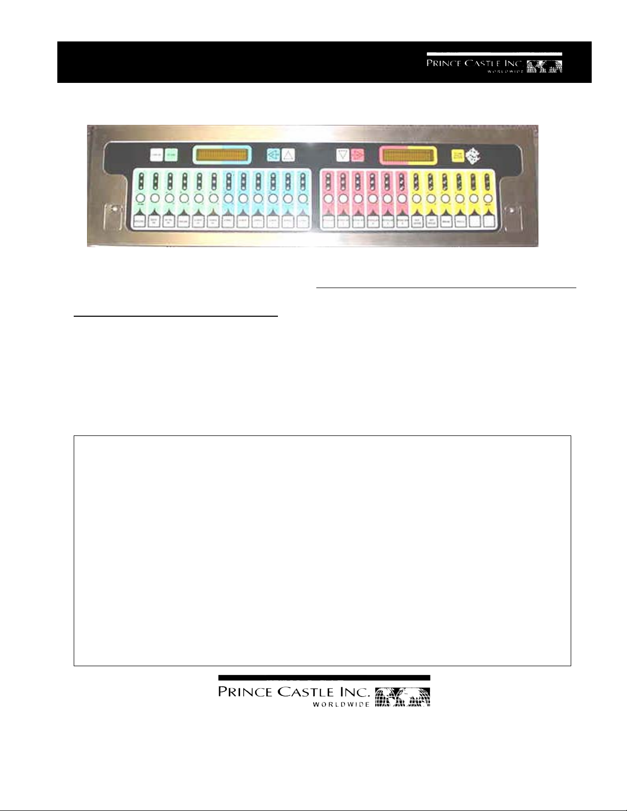
893 Series Timers
ELECTRICAL
90-130 Volts
50/60 Hz
15 Watts
UL, cUL & NSF Listed
TABLE OF CONTENTS PAGE
Installation..................................................................... 2
Programming.............................................................. 2-6
Operation ....................................................................... 5
Parts List....................................................................... 7
Exploded View .............................................................. 7
Troubleshooting ............................................................ 8
LIMITED WARRANTY
This product is warranted to be free from defects in material
and/or workmanship for a period of 1 year from date of original
installation, not to exceed 18 months from the date of
manufacture.
Any component which proves to be faulty in material and/or
workmanship will be replaced or repaired (at the option of
Prince Castle, Inc.) without cost to the customer for parts and
labor. This equipment is portable; charges for on-location
service (e.g., trip charges, mileage) are not included in the
provisions of this warranty.
This warranty is subject to the following exceptions/conditions:
• Use of any non-genuine Prince Castle parts voids this
warranty.
• All labor to be performed during regular work hours.
Overtime premium (the incremental amount) will be charged
to the customer.
• Damage caused by carelessness, neglect and/or abuse
(e.g., dropping, tampering or altering parts, equipment
damaged in shipment, by fire, flood or an act of God) is not
covered under this warranty.
• All problems due to operation at voltages other than that
specified on equipment nameplates are not covered by this
warranty. Conversion to correct voltage is the customer’s
responsibility.
• This equipment must be serviced by Prince Castle
Authorized Service Agency or a Prince Castle Service
Technician during the warranty period.
355 East Kehoe Blvd. z Carol Stream, IL 60188
Tel: (630) 462-8800 z Fax: (630) 462-1460
Toll Free: 1-800-PCASTLE
893-504revC P
rinted in USA 8/06 © 2006
Page 2

INSTALLATION
1. Remove timer from shipping box. Packed
with timer, there are programming
instructions, three (3) product strips, one
(1) grill and two (2) fryers (standard and
reverse).
2. The timer is shipped programmed for grill
use. If the timer is to be used on the fryer,
follow the appropriate programming
instructions (standard or reverse).
3. Install the appropriate product strip.
4. Remove the old timer and bracket.
5. Clean surface and install the new bracket.
a. There are (14) 5/16” holes spaced
around the opening in the back of the
bracket to use for mounting. If the holes
do not line up with existing holes, new
holes need to be drilled.
b. Cover grill or fryer to prevent shavings
from falling into fryer, grill or food
prep areas.
c. Use timer bracket as a template to mark
holes and drill as necessary. To insure a
safe installation, there should be a
minimum of three self-tapping screws
(top/bottom and one on each end).
d. In some restaurants, it will be necessary
to transfer the VCK bracket from the
thumbscrews provided.
6. Run timer power cord to nearest 120V
outlet and install timer on bracket using
the thumbscrews provided.
ELECTRICAL REQUIREMENTS
1. There must be a 120V receptacle within 5
feet of the center of the timer.
2. Cords should not be run in a way that would
cause a hazzard.
3. If the receptacle is not available, find the
transformer for the existing timer and
extend that circuit to the new bracket.
In the following descriptions,
Arrow,
is for the DOWN Arrow, is for the
is for the UP
QUICK START INSTALLATION
To Select Grill or Fryer Mode:
1. Press the Logo Button and the SCAN/
ENTER Button simultaneously for 6 seconds.
2. Press the
Button to select: 1) Grill, 2)
Fryer, or 3) Fryer Reverse.
3. Press the SCAN/ENTER Button to save.
Continue to set the Real Time Clock and
Date, or press Logo to exit programming.
4. Use the SCAN>Button to move cursor.
5. Use the Number Buttons to make changes
(Note: if a number on the bottom row needs to
be entered, use either of the
Buttons located
on the far ends of the product strip to shift down.
6. When setting AM/PM, use the
and
Buttons.
7. Press the SCAN/ENTER Button to save (a
test tune will play).
8. Press the Logo Button to exit
programming
ONGONING
Volume Control
• Use the
or Button to change volume
level when timer is not in operation.
Productivity Messages (“STIR SAUCE-CHK
WATER”)
• The display will continue to show unless the
CANCEL Button is pressed, or another message comes up.
• The audio “alarm” heard when productivity
message is displayed will stop sounding in
about 5 seconds.
• If desired, pressing the CANCEL Button can
terminate this “alarm”. Note: this will also remove the message that is displayed.
PROGRAMMING INSTRUCTIONS
1. Scope
There are four different programming modes. In
the specifications below, they are referred to as
levels. There is also a volume level adjustment
available.
LEFT Arrow, and
Printed in USA 8/06 © 2006
is for the RIGHT Arrow.
Volume Level Adjustment is used to set the
2
893-504revC
Page 3

desired volume level.
pressed:
Level 1 is used to configure the timer for Grill or
Fryer, Standard or Reverse. It also allows set-up
of the Real Time Clock and a “User Test Mode”
Top Line Reverse
Bottom line Fryer Timer ENTER=SAVE/
Left Display Right Display
which allows verification that all Displays,
LED’s, Switches and Speakers are working.
• When the ENTER button is pressed, the
Level 2 is used to change only the time values
of a timer.
Level 3 is used to completely edit a timer:
timer configuration is saved and the displays
change to setting the Real Time Clock:
Left Display Right Display
menu names, time values, alarm cancels and
duty function name.
Level 4 is used to edit, schedule and set active
Top Line
Bottom line
Time: 09:00AM
Date: 05/14/99
status for productivity messages.
2. Volume Level
When no timers are running and when the 893
is not in a programming mode, the Up and
Down Arrow Buttons will adjust the volume level.
Press and release the Up Arrow to increase
volume level one step. Press and release the
Down Arrow Button to decrease the volume
level one step. There are seven volume steps
available and a tone sounds while the Up or
Down Arrow Buttons are pressed to aid in
choosing the desired setting.
3. Level 1
1. Configure a timer for Grill or Fryer timing.
2. Set standard or reverse timer layout.
3. Set the Real Time Clock.
4. Test Displays, Switches, LED’s and
Speakers.
Procedure:
• Press and hold the LOGO button and then
immediately press and hold the ENTER. Hold
both buttons for 6 seconds.
• As shown below, the example timer is configured for a Reverse Fryer. Press the ENTER
button to accept (save) this configuration. Use
Initially, the cursor is positioned over the first
digit of the time of day. Use the
buttons to move the cursor. Use the Number
buttons to make changes at each cursor location for time values. When setting AM/PM, use
the
and arrow buttons to choose. The
ENTER button saves changes and moves on to
the Test Mode; the LOGO button ends level 1
programming.
• When the ENTER button is pressed, the Time
of Day configuration is saved and the displays
change to the Test Mode. All LED’s will begin
flashing on and off, the Displays will alternate
between all segments on and all segments off
and the Speakers will play a test tune. View
each LED and Display segment to be sure
each turns completely on and completely off.
Additionally, press and hold any button, except
ENTER or LOGO, and its reference number will
appear on each Display alternately. Press and
release the LOGO button to exit level 1 programming or press and release the ENTER
button to exit the test mode and move back to
the Timer Configuration Mode.
the or arrow buttons to choose another
Timer Mode configuration, then press the
4. Level 2
ENTER button to select (save) the new timer
configuration. NOTE: The new timer configuration will not be saved if only the LOGO button is
893-504revC P
3
TO CHANGE
LOGO=DONE
=MOVE/
INPUT NUMBER
ENTER=SAVE/
LOGO=DONE
and arrow
rinted in USA 8/06 © 2006
Page 4

To change only the time values of a timer.
Procedure:
• Press and hold the logo button then immediately press and hold the timer button to
change. Hold both buttons for 6 seconds.
• Use the arrow keys to move the cursor
through the time value locations. Make
changes at the cursor location using the
Number buttons.
• Press the Enter button to store the
changes. Press the Logo button to stop
editing this timer.
The opening displays:
Left Display Right Display
• As a reference for this step in the programming sequence, the left panel of the display will
not change. It will continue to show the menu
name and total cook time.
• The cursor will be at the HOLD time. Use the
and arrow button to move the cursor. Use
the Number buttons to change the time values.
• Press the ENTER button to save all
changes. Changes will not be saved if only the
LOGO button is pressed. The display will
change to show the opening window. Press the
ENTER button to review all changes.
• Press the LOGO button to return to the beginning of level 2 and choose another timer to edit.
Press the LOGO button again to exit level 2.
Top Line XXXX ll 1ST A ALM
Bottom line
COOK T:CT ll 0:00
=MOVE/
INPUT NUMBER
ENTER=SAVE/
LOGO=DONE
Where:
XXXXXXXX = Menu Name
T:CT = the Total Cook Time
0:00 = The time value for the First Duty
A = Auto Alarm Cancel
M = Manual Alarm Cancel
• The cursor will be at the T in the T:CT. Use
the
and arrow buttons to move the cursor.
Use the Number buttons to make time value
changes at the cursor location.
• Use the arrow buttons to move the cursor
to the 1ST duty cook time. Use the Number
buttons to make time value changes at the
cursor location.
• Press the ENTER button to save changes
and move to the next step. Press the LOGO
button to stop editing this timer. No changes are
saved unless the ENTER button is pressed.
Set the Hold time:
Left Display Right Display
Top Line XXXX ll HLD A ALM
Bottom line
COOK T:CT ll 0:00
=MOVE/
INPUT NUMBER
ENTER=SAVE/
LOGO=DONE
5. Level 3
To assign or rename the selected button menu
name, change time values, and alarm cancel
modes.
Procedure:
• Press and hold the logo button for six seconds.
• Press the timer button to edit.
• Use the arrow keys and follow prompts to
make changes.
• Review changes.
•
Press another button to edit and make changes.
• Press the logo button to quit level 3.
The opening window:
Left Display Right Display
Top Line Press Button To Edit Press Button To
Edit
Bottom line LOGO=DONE
• Select a timer button to edit.
• Save and review all changes.
• Select another button to edit or press the
logo button to quit.
Set the total cook time, menu name, the first
duty time, alarm, and duty name for a selected timer:
Left Display Right Display
Printed in USA 8/06 © 2006
4
893-504revC
Page 5

Top Line XXXX ll 1ST A ALM =MOVE/
INPUT NUMBER
Bottom line
COOK T:CT ll 0:00
ENTER=SAVE/
LOGO=DONE
Where:
XXXXXXXX = Menu Name
T:CT = the Total Cook Time
0:00 = The time value for the First Duty
A = Auto Alarm Cancel
M = Manual Alarm Cancel
• The cursor is at the first character location of
the menu name. Use the
and arrow
buttons to move the cursor through the Menu
Name (XXXXXXXX). Use the keypad alphanumeric characters identified on the buttons to
enter the menu name.
• Use the and arrow buttons to move the
cursor to the T:CT. Use the Number Buttons to
make changes at the cursor location.
• The cursor will be at the 2nd alarm cancel.
Use the
and arrows to select the alarm
cancel desired.
• Press the ENTER button to save changes
and to move to the next step.
Set the Hold time and alarm cancel:
Left Display Right Display
Top Line XXXX ll HLD A ALM
Bottom line
COOK T:CT ll 0:00
=MOVE/
= CHANGE
ENTER=SAVE/
LOGO=DONE
• As a reference, the left panel of the display
will continue to show the menu name and total
cook time.
• The cursor will be at the Hold time. Use the
and arrows to move the cursor and use
the Number buttons make changes.
• Use the
and arrow buttons to move the
cursor to the 1ST duty time. Use the Number
buttons to enter the time value at the cursor
location.
• Use the
the alarm cancel position. Use the
arrow button to move the cursor to
or
arrow to select between Auto or Manual cancel.
• Use the
function (YYYY). Use the
arrow button to move the duty
or arrow but-
tons to scroll through function names.
• Press the ENTER button to save changes
and to move to the next step.
Set the second function alarm:
Left Display Right Display
Top Line XXXX ll 2ND A ALM
Bottom line
COOK T:CT ll 0:00
=MOVE/
= CHANGE
ENTER=SAVE/
LOGO=DONE
• As a reference, the left panel of the display
will continue to show the menu name and total
cook time.
• Use the arrow to move the cursor to the
HOLD alarm cancel position. Use the
and
arrows to select the alarm cancel desired.
• Press the ENTER button to save all
changes. Changes will not be saved if only the
LOGO button is pressed. The display will
change to show the opening window. Press the
ENTER button to review all changes.
• Press the LOGO button when reviewing and
editing are done.
Select another button to edit or quit:
Left Display Right Display
Top Line Press Button To Edit Press Button To
Edit
Bottom line LOGO=DONE
• Press another button to edit or the LOGO
button to quit level 3.
6. Level 4
To schedule and edit productivity messages.
893-504revC P
5
rinted in USA 8/06 © 2006
Page 6

Procedure:
• Press and hold the LOGO button then immediately press and hold the CANCEL button.
Hold both buttons for 6 seconds.
• Use the arrow keys to move the cursor.
Make changes at the cursor location.
• Press the Enter button to store the changes.
• Press the LOGO button to exit level 4.
• The cursor will be at the first character of the
start time. Use the and buttons to move
the cursor and the Number buttons to change
the value at the cursor location. The time can be
set for AM or PM using the and buttons
when the cursor is in that location. Press the
Enter button to save changes.
Opening Display:
Left Display Right Display
Top Line MESSAGE X (Active)
Bottom line
XXXXXXXXXXXXXX
TO VIEW
MESSAGES
ENTER=EDIT/
LOGO=DONE
Scroll through each message using the and
arrow buttons. To edit the message being
displayed, press Enter. The displays change to:
Left Display Right Display
Top Line Edit MESSAGE X =MOVE/
INPUT LETTER
Bottom line
XXXXXXXXXXXXXX
ENTER=SAVE/
LOGO=DONE
• Use the and arrow buttons to move the
cursor through the message. Use the keypad
(the characters identified for buttons 3 through
22) to enter the desired characters. Press the
ENTER button to save the changes and move to
set the active status of the message:
Left Display Right Display
Top Line EDIT MESSAGE X
Bottom line
ACTIVE
TO
CHANGE
ENTER=SAVE/
LOGO=DONE
• Use the or button to set the message
active or inactive. Press the ENTER button to
save changes and move to the scheduling
steps.
Left Display Right Display
Top Line EDIT MESSAGE X
Bottom line
Printed in USA 8/06 © 2006
START AT YY:YY AM
=MOVE/
INPUT NUMBER
ENTER=SAVE/
LOGO=DONE
Left Display Right Display
Top Line EDIT MESSAGE X
Bottom line
Repeat Every YY MIN
=MOVE/
INPUT NUMBER
ENTER=SAVE/
LOGO=DONE
The cursor will be on the first time value of the
repeat cycle time. Use the or button to
move the cursor and the Number buttons to
change the time value. Press the ENTER
button to save changes and the LOGO button to
quit editing the chosen message and return to
viewing the messages.
• Preprogrammed Productivity Messages
and Times:
The 893Timer comes with three messages
pre-loaded in memory for Grill Timer mode only.
The messages and times are:
No. Message Start Time Repeats every
1 STIR SAUCE/
CHECK WATER 6:05 AM 15 minutes
2 CHECK/SCRAPE GRILL 6:10 AM 15 minutes
3 WASH HANDS 7:00 AM 10 minutes
4 available ——— ———5 available ———- ———-
893 INSTALLATION INSTRUCTIONS
893 Timer
1. Install the timer following the 893 series
timer installation instructions.
2. From the 893 series Installation Instruc-
tions, use the Quick Start Instructions to
configure the timer for grill or fryer operation.
6
893-504revC
Page 7

EXPLODED VIEW
Power Cord 72-282 (not shown)
Strain Relief 66-055 (not shown)
893-092
Menu Strip Door
893-086
88-709 Rear Panel
Speaker
893-022
893-078
VF Display
Backer Plate
7
893-070
Main PCB
893-072
893-077 Display PCB (2)
Chassis
893-090
Overlay
88-709
Speaker
893-092
Menu Strip
Door
893-504revC P
7
rinted in USA 8/06 © 2006
Page 8

TROUBLESHOOTING GUIDE
PROBLEM
A. No displays or indicators lit. Unit unplugged. Plug unit in.
Store's circuit breaker blown. Reset breaker.
Circuit inoperable. Replace Main Circuit
B. Absence of Audio Alarm. Speaker inoperable. Replace Speaker.
Circuit inoperable. Replace Main Circuit
C. Unable to start, stop, or store Circuit inoperable. Replace Switch Panel. If
timer presets in program mode. problem persists, replace
Missing or abnormal characters
in displays.
CAUSE
SOLUTION
Board.
Board.
Main Circuit Board
Printed in USA 8/06 © 2006
8
893-504revC
Page 9

NOTES
893-504revC P
9
rinted in USA 8/06 © 2006
 Loading...