

Page 1
OPERATING
This product is warranted to be free from defects in material
and/or workmanship for a period of 1 year from date of original
installation, not to exceed 18 months from the date of
manufacture.
Any component which proves to be faulty in material and/or
workmanship will be replaced or repaired (at the option of
Prince Castle, Inc.) without cost to the customer for parts and
labor. This equipment is portable; charges for on-location
service (e.g., trip charges, mileage) are not included in the
provisions of this warranty.
This warranty is subject to the following exceptions/conditions:
• Use of any non-genuine Prince Castle parts voids this
warranty.
• All labor to be performed during regular work hours.
Overtime premium (the incremental amount) will be charged
to the customer.
• Damage caused by carelessness, neglect and/or abuse
(e.g., dropping, tampering or altering parts, equipment
damaged in shipment, by fire, flood or an act of God) is not
covered under this warranty.
• All problems due to operation at voltages other than that
specified on equipment nameplates are not covered by this
warranty. Conversion to correct voltage is the customer’s
responsibility.
• This equipment must be serviced by Prince Castle
Authorized Service Agency or a Prince Castle Service
Technician during the warranty period.
LIMITED WARRANTY
840-507revB
Printed in USA 3/06 © 2006
INSTRUCTIONS
Multi-Function Timers
840-T, 840-TJ & 840-TF
Series
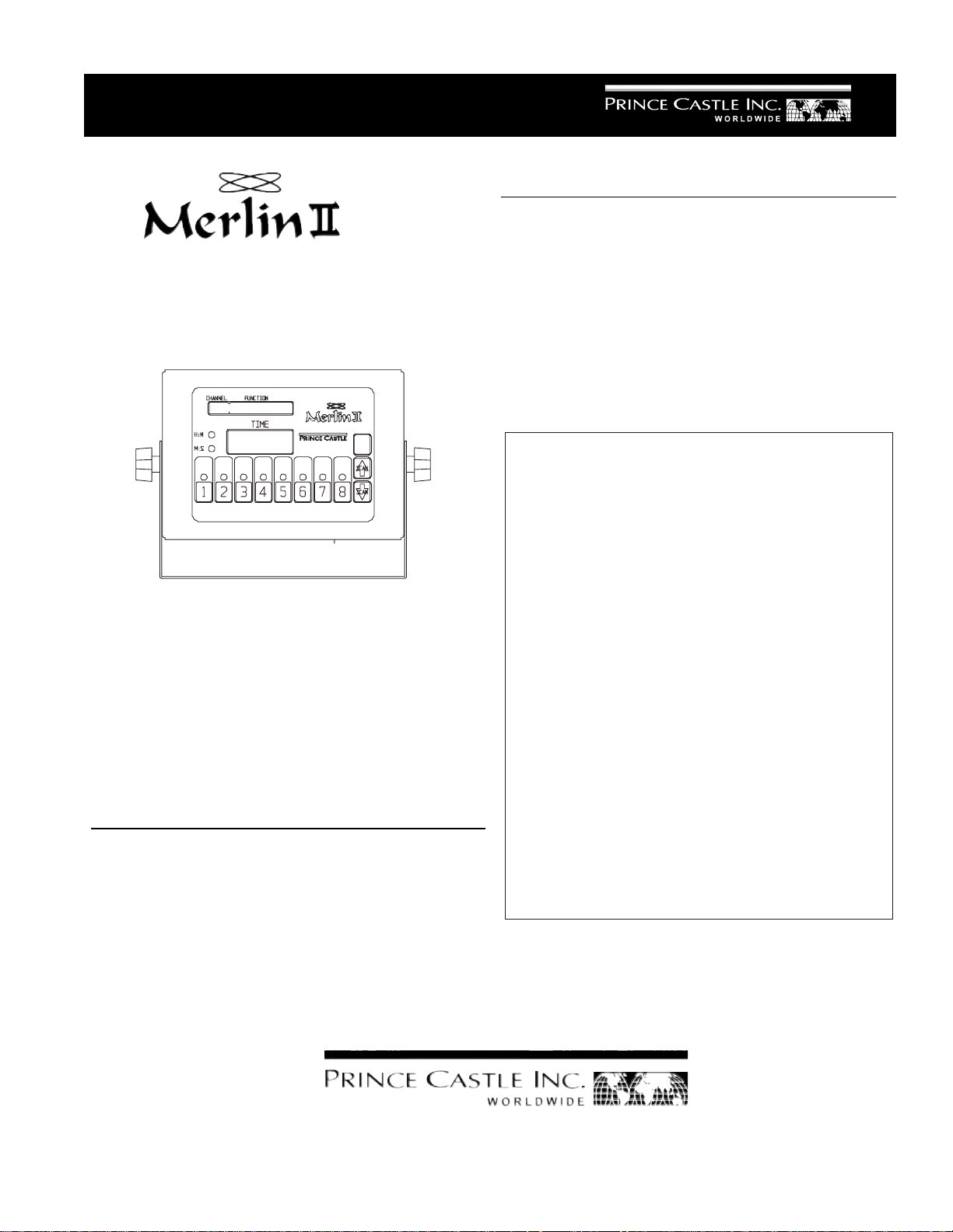
Pictured Model 840-T8
Prince Castle’s second generation of Merlin Timers
feature a new slim design which gives you mounting
flexibility . The 840 Series Timers are designed so
each channel can be programmed independently,
and used simultaneously. The push of a button
activates each channel, and a alarm and multicolored flashing channel buttons alert the operator
when timing is complete.
ELECTRICAL
840-T Series 840-TJ Series
120 Volts 100 Volts
50-60 Hz 50/60 Hz
TABLE OF CONTENTS PAGE
Installation..................................................................... 2
Programming..............................................................2-3
Operation....................................................................... 4
Cleaning ........................................................................ 4
Parts List ....................................................................... 5
Exploded View.............................................................. 5
Troubleshooting ............................................................ 6
Wiring Diagrams........................................................... 6
840-TF Series
220-240 Volts
50/60 Hz
355 East Kehoe Blvd. z Carol Stream, IL 60188
Tel: (630) 462-8800 z Fax: (630) 462-1460
Toll Free: 1-800-PCASTLE
Page 2
INSTALLATION
Printed in USA 3/06 © 2006
840-507revB
1. After you have removed the timer from the carton,
inspect the unit for signs of damage. If there is
damage to the unit:
z Notify carrier within 24 hours after delivery.
z Save carton and packing materials for inspection
purposes.
z Contact your local dealer or, if purchased di-
rectly, the Prince Castle Customer Sales
Department at 1-800-722-7853 to arrange for
a replacement to be sent.
2. Verify that all parts have been received. Mounting
bracket and hardware are provided.
3. To mount the timer, place mounting brackets in desired location. Scribe location of mounting holes,
center punch, and drill holes. Attach timer to mounting brackets placing star washer between bracket and
timer.
PROGRAMMING
Note: The 6 following functions can be programmed
on each channel:
Total Cook Time: ( Factory Preset 3:00 Minutes)
2. Select and press the timer channel to be programmed. The LED indicator for the selected
button will turn yellow and a beep will sound. The
CHANNEL/FUNCTION display will read,
CKT=COOK TIME with up and down arrows. The
current complete cook time (Factory Preset 3:00
M:S) for that channel will be displayed in the TIME
display, and the time value will indicate either H:M
or M:S.
CKT=COOK TIME
3 : 0 0
ENTER
3. At this point, program in your complete cook time
by using the SCAN/UP Arrow or the SCAN/DOWN
Arrow button. Once you have reached your desired time press the ENTER button to store your
complete cook time. Note: The Enter button must
be pressed after any time changes in the cook,
duty or hold functions or the the time change will
not be stored.
1st Duty During Cook Time: (Factory Preset :30 Sec.)
2nd Duty During Cook Time:(Factory Preset 1:00 Min.)
3rd Duty During Cook Time:(Factory Preset 1:30 Min)
Hold Time: (Factory Preset 10:00 Minutes)
Duty During Hold Time: No Preset Time.
Each function programs in the same manner, first
setting the time, then setting the alarm cancel
mode (Automatic or Manual) and finally naming the
function.
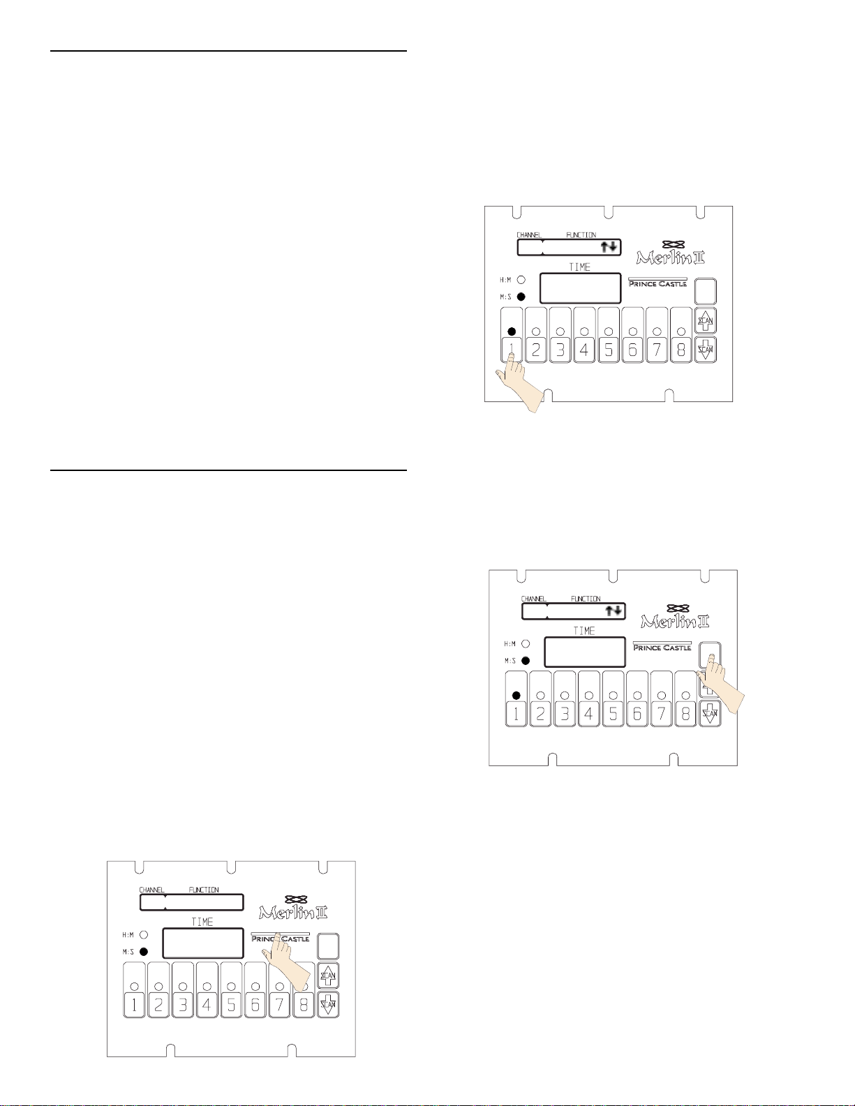
1. To program, press and hold the PRINCE CASTLE
LOGO for eight seconds, a beep will sound and the
CHANNEL/FUNCTION DISPLAY will read SEL CH/
LOGO = QUIT.
SEL CH/LOGO = QUIT
ENTER
CKT=COOK TIME
6 : 0 0
ENTER
IMPORTANT: To change from Minutes and Seconds M:S to Hours and Minutes H:M. Press and
hold the SCAN/UP Button. When the display
reaches 59:59 it will automatically change to 1:00
Hour and the LED will switch from M:S to H:M.
The program value for the H:M indicator is from
1:00 hour to 17 hours: 59 minutes.
2
Page 3

4. Once you press ENTER ,The CHANNEL/FUNC-
840-507revB
Printed in USA 3/06 © 2006
TION display switches to CKC=MAN CANCEL, this
allows you to select a manual or an automatic
alarm cancel , press the SCAN UP arrow or SCAN
DOWN arrow to toggle between AUT and MAN
Cancel. Press the ENTER button to store your
selection.
CKC=MAN CANCEL
D1T=DUTY 1 TIME
0 : 30
ENTER
6 : 0 0
ENTER
5. After you press ENTER, the CHANNEL/FUNCTION
display will change to CKL=COOK. To select an
alternate function (see list below) use the SCAN
UP or SCAN DOWN arrows. Press ENTER to store
the selection. The function name selected will be
displayed during the final countdown sequence.
Note: The function name options are as follows:
BAKE, BAKE MORE, BASTE, BRAISE, CHILL,
COOK, COOK DUTY 1, COOK DUTY 2, COOK
DUTY 3, COOK MORE, COVER, DISCARD,
DONE, DROP, END, FOLD, FRY, FRY MORE,
GRILL, GRILL MORE, HOLD, HOLD DUTY, MIX,
POACH, POUR, REMOVE, ROTATE, SEAR,
SHAKE, SIDE 1, SIDE 2, STIR, TURN, WHIP And
WRAP.
CKL=COOK
7. To set the DUTY TIME Press the SCAN UP Arrow
Button. If no DUTY TIME is desired use the SCAN
DOWN Arrow Button to set the DUTY TIME to 0:00,
press ENTER to store your setting.
DT1=DUTY TIME1
0 0 : 0 0
ENTER
8. Once you press ENTER ,The CHANNEL/FUNCTION display switches to DT1=MAN CANCEL, this
allows you to select a manual or an automatic
alarm cancel , press the SCAN UP arrow or SCAN
DOWN arrow to toggle between AUT and MAN
Cancel. Press the ENTER button to store your
selection.
6 : 0 0
ENTER
6. After pressing the ENTER button, the CHANNEL/
FUNCTION display will read CKT=COOK TIME.To
move on to the DUTY function press the selected
CHANNEL BUTTON once.The CHANNEL/FUNCTION display reads DT1=DUTY TIME1 and :30
Seconds (The Factory Preset) will appear in the
TIME DISPLAY.
DT1=MAN CANCEL
0 : 0 0
ENTER
9. After you press ENTER, the CHANNEL/FUNCTION
display will change to DT1=COOK. To select an
alternate function (see list by step 5) use the
SCAN UP or SCAN DOWN arrows. Press ENTER
to store the selection. The function name selected
will be displayed during the DUTY 1 sequence.
3
Page 4

10. After pressing the ENTER button, the CHANNEL/
Printed in USA 3/06 © 2006
840-507revB
FUNCTION display will read DT1=DUTY TIME1.To
move on to the DUTY 2 function press the selected
CHANNEL BUTTON once.The CHANNEL/FUNCTION display reads DT2=DUTY TIME 2 and :00
Seconds (The Factory Preset) will appear in the
TIME DISPLAY.
11. Repeat steps 6-10 for DUTY 2, DUTY 3, HOLD and
HOLD DUTY Settings. NOTE: The HOLD FUNCTION is preset at the factory for 10:00 M:S, if no
HOLD TIME is desired you must set the HOLD
FUNCTION to 00:00.
12. After you have completed programming the HOLD
DUTY FUNCTION, press the CHANNEL BUTTON
again, the display will read SEL CH/LOGO=QUIT.
Select another channel button to program, or press
the PRINCE CASTLE LOGO to return to the RUN
MODE
13. You can change the sound level of the alarm in
RUN MODE. Press and hold the PRINCE CASTLE
LOGO ; then, within six seconds, press either the
SCAN UP Arrow button or the SCAN DOWN Arrow
button. The SCAN UP Arrow button adjusts the
sound level to the louder alarm, and the SCAN
DOWN Arrow button adjusts the sound level to the
lower alarm.
OPERATION
IMPORTANT: The channel timer button’s multicolored LED indicator shows the status of the
timer. The indicator has three colors: green,
yellow, and red. The LED will be green during
the first 70% of the countdown. It changes to
yellow during the next 20% of the countdown. It
will be red during the final 10% of the countdown,
and will start flashing red once the time has run
out.
Note: If a Manual Cancel is programmed into a
duty function the LED will flash red until the
channel button has been pressed. If an Automatic Cancel is programmed the LED will flash
green for 5 seconds and the alarm will automatically turn off.
3. The timer will countdown from the programmed
value to zero. When the complete cooked time is
finished, the display flashes 0 0 and the alarm
sounds.
4. When the timing cycle is complete, and the alarm
sounds, press the channel button with the flashing
red indicator to cancel the alarm.
5. The scan feature is used to check the time values on
other active channels. There are two different ways
to scan active channels. Press the SCAN/UP or
SCAN/DOWN button.Or press any of the active
timer CHANNEL buttons. If no other button is
pressed within 5 seconds, the display will change to
show the timer with the least amount of time left.
1. Press a channel button to activate a timing cycle.
(All channels can be activated and running at the
same time.) The channel with the least amount of
function time remaining will be displayed in the
CHANNEL/FUNCTION display along with the next
function. The time remaining will countdown in the
TIME display, and the time value M:S or H:M will be
illuminated.
1 - COOK
3 : 0 0
ENTER
2. Press the desired channel button three times within
five seconds to cancel an active timing cycle.
CLEANING
1.Do not allow grease to build up on the timer, wipe it
down daily with clean damp cloth.
IMPORTANT: Do not use abrasive or chemical cleaners
on your timer, this may cause damage to the overlay.
4
Page 5

EXPLODED VIEW
840-507revB
Printed in USA 3/06 © 2006
7
8
6
5
2
3
1
4
9
PART LIST
ITEM PART NUMBER DESCRIPTION
1 69-079 Rivet Plastic Push Pin
2 840-100 Rear Cover
3 840-108S Main P.C.Board
840-109S Auxillary P.C.Board
(840-T8D & 840-T16D)
4 71-142-02S Display Board
5 88-653-2-4S Speaker Assy.
6 840-096S Switch Panel Assy.
(840-T8 Series)
840-110S Switch Panel Assy. (840-T4 Series)
7 70-048S Knob W/Washer (Pkg of 2)
8 840-103 Chassis (840-T4 & T8)
840-115 Chassis
(840-T8D & T16D)
9 72-292S Power Supply (110-120V)
72-293-01JS Power Supply (100V)
72-293-04FS Power Supply (220-240V)
5
Page 6

WIRING DIAGRAM 840-T Series
Printed in USA 3/06 © 2006
840-507revB
TROUBLESHOOTING GUIDE
PROBLEM
A. No displays or indicators lit. Unit unplugged. Plug unit in.
Store's circuit breaker blown. Reset breaker.
Defective transformer. Replace Main Circuit Board.
Circuit inoperable. Replace Main Circuit Board.
B. Absence of Audio Alarm. Speaker inoperable. Replace Speaker.
Circuit inoperable. Replace Main Circuit Board.
C. Unit will not enter program All channels are still counting. Wait until channels are in stop
mode. mode.
Logo Switch inoperable. Replace Switch Panel.
D. Unit enters program mode. The channel is still counting. Wait until channel is in stop mode.
but cannot change times. Arrow Switch inoperable. Replace Switch Panel.
Circuit Inoperable Replace Main Circuit Board.
CAUSE
SOLUTION
E. Unable to start, stop, or store Circuit inoperable. Replace Switch Panel. If
timer presets in program mode. problem persists, replace Main
Missing or abnormal characters Circuit Board.
in displays.
6
 Loading...