

Page 1
OPERATING
INSTRUCTIONS
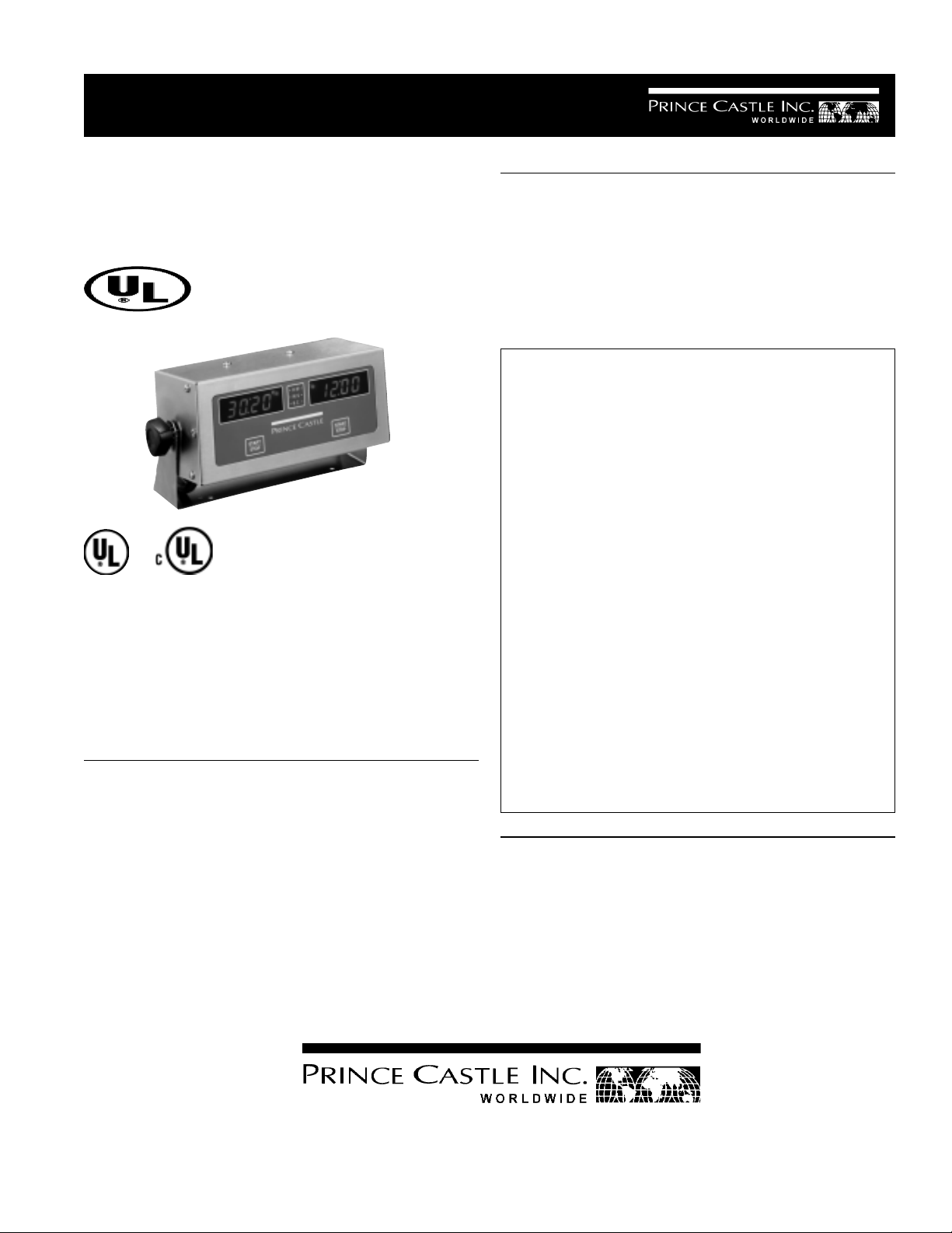
Multi Function
Grill Timer
Model No. 835-GT2 Series
Prince Castle's Merlin Timers are simple to program
and easy to use. The push of a button activates
each channel. An audible alarm and flashing channel button alert the operator when timing is complete. The 835-GT2 functions include: sear, turn, and
remove. An LED will light and show the function
being timed.
SPECIFICATION
TABLE OF CONTENTS PAGE
Installation............................................................... 2
Programming........................................................... 2
Operating ................................................................. 3
Cleaning and Calibration........................................ 3
Parts List/Exploded View ................................... 4-5
Troubleshooting ...................................................... 5
Wiring Diagram ....................................................... 6
LIMITED WARRANTY
This product is warranted to be free from defects in
material and/or workmanship for a period of two (2)
years from date of original installation, not to exceed 30 months from date of shipment from our
factory. Any part or component which proves to be
faulty in material and/or workmanship within the
warranty period will be replaced or repaired without
cost to the customer for parts or labor (at the option
of Prince Castle, Inc.).
This warranty is subject to the following exceptions/
conditions:
z Any use of non-genuine Prince Castle spare
parts voids this warranty.
z All labor shall be performed during regular work-
ing hours. Overtime premium will not be covered.
z Damage caused by carelessness, neglect, and/or
abuse (e.g., using wrong current, dropping, tampering with or altering electrical components, or improper cleaning) is not covered by the terms of this
warranty. Equipment damaged in shipment, by fire,
flood or an act of God is not covered.
835-T Series Dimensions
Width 10” (25.4 cm)
Depth 33/4 ” (9.52 cm)
Height 33/4” (9.52 cm)
Shipping Weight 6lbs. (2.72 kg.)
355 East Kehoe Blvd. z Carol Stream, IL 60188
Printed in February 1998
Prince Castle Inc.
Tel: (630) 462-8800 z Fax: (630) 462-1460
Toll Free: 1-800-PCASTLE
ELECTRICAL
835-GT2 835-AF 835-AJ
110-220 Volts 220-240 Volts 100 Volts
60Hz 50 Hz 50-60 Hz
Single phase Single phase Single phase
8 Watts 8 Watts 8 Watts
834-502
Page 2
INSTALLATION
1. After you have removed the timer from the carton,
inspect the unit for signs of damage. If there is
damage to the unit:
Notify carrier within 24 hours after delivery.
Save carton and packing materials for inspection
purposes.
Contact the Prince Castle Customer Sales
Department at 1-800-722-7853 to arrange for
a replacement to be sent.
2. Verify that all parts have been received.
CAUTION: Solid state components in this
product are designed to operate reliably in
a temperature range up to 150° F (65.6°C).
When installing it should be confirmed that
the ambient temperatures at the mounting
sight do not exceed 150°F (65.6°C).
3. Mount brackets (2) at desired location. Scribe
location of mounting bracket holes and center
punch. Drill holes with a No. 29 (3.70 mm) drill and
thread hole with a # 8-32 tap.
IMPORTANT: After drilling one hole, attach timer to
bracket so the second bracket can be mounted in the
proper location. See figure 1.
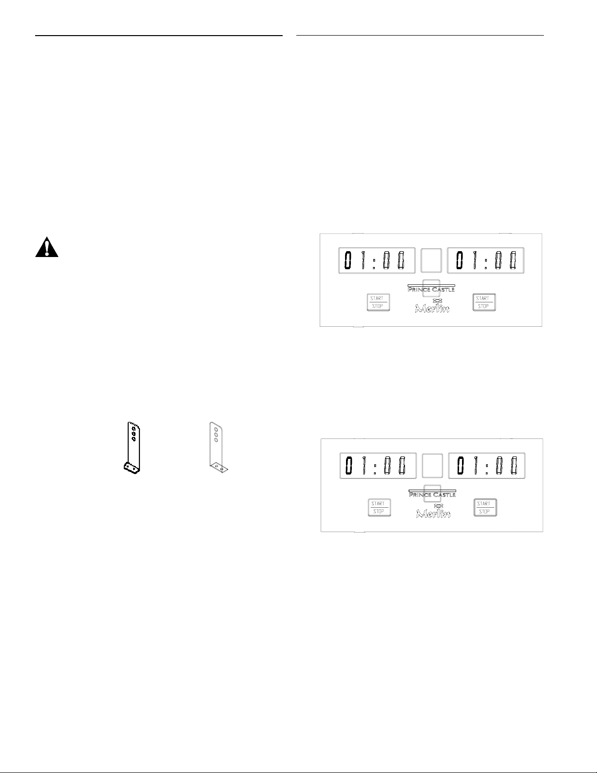
PROGRAMMING
1. Press and hold PRINCE CASTLE LOGO for 5
seconds. The display will become brighter, a tone
will sound, and the left most digit on both displays
will flash. The times for the three functions: SEAR,
TURN, and REMOVE can now be set. (One at a
time) Factory preset times are: Sear 15 seconds,
Turn 1 minute, Remove 1 minute. See figure 2.
figure 2
SEAR
TURN
REMOVE
2. The LED light that corresponds to the SEAR function will be lit. The SEAR function time can now be
set. See figure 3.
figure 1
4. Plug timer into proper voltage receptacle.
IMPORTANT: This should be a dedicated outlet. No
other equipment should be operating on this line (i.e.
fryers, refrigerators, cash registers, etc.)
figure 3
SEAR
zz
TURN
REMOVE
IMPORTANT: SEAR and/or TURN function can be set
at 00:00 if not desired.
3. Push the START/STOP to change the flashing
digit under the display until the desired number is
reached. See figure 4.
2
Page 3

figure 4
SEAR
zz
TURN
REMOVE
OPERATION
1. Press START/STOP under the desired display.
See figure 7.
figure 7
LEFT DISPLAY RIGHT DISPLAY
4. Push the PRINCE CASTLE LOGO to advance a
digit (digit will start flashing).
5. Repeat steps 3 and 4 for all four digits.
6. When all four digits are set to the desired time,
press the PRINCE CASTLE LOGO to move to the
next function. The LED will switch to TURN. See
figure 5.
figure 5
SEAR
TURN
zz
REMOVE
7. Repeat steps 3, 4, 5, & 6 to set desired times for
TURN and REMOVE functions.
SEAR
TURN
REMOVE
z
z
START/STOP
2. When the time reaches 0 0 : 0 0 for each function
a two toned alarm will sound. To cancel the alarm,
press the START/STOP square. The timer will
automatically start counting down the next function after the previous function sounds regardless
of when sound is cancelled. See figure 8.
figure 8
BEEP
SEAR
TURN
z
REMOVE
z
BEEP
8. After setting the REMOVE function press PRINCE
CASTLE LOGO and the unit will return to the RUN
MODE. The unit is ready for operation. See figure 6.
figure 6
SEAR
TURN
REMOVE
zz
3. When pressing the START/STOP square for the
remove alarm, the timer will go back to the sear
function, the display will be at half brightness, and
remain inactive until pressed again.
IMPORTANT: Pressing the START/STOP square
during a cooking sequence while an alarm is not
sounding will cancel the sequence.
3
Page 4

EXPLODED VIEW
IMPORTANT: Timer must operate on a dedicated
outlet. No other equipment should be plugged into
this outlet (i.e. refrigerators, cash registers, etc.). If
unit malfunctions the customer should unplug it for
approximately ten seconds. If malfunction exists,
and the Troubleshooting Chart on the next page is of
no help, the printed circuit board should be replaced
by a qualified technician.
4
Page 5

PARTS LIST
ITEM PART NO. DESCRIPTION
1 836-9 Front Cover
2 836-5 Front Panel/Switch Assy
3 835-9S P.C.Board Assy
4 828-23S Speaker Assy.
5 482-18 Speaker Grease Seal
6 307-76S Transformer Assy.
7 72-091S Power Cord
8 66-006 Strain Relief
9 834-3 Function Strip (835-GT2)
10 89-766 Spacer
11 835-2 Back Cover
12 752-6S Mounting Bracket
13 70-039 Knob
14 834-9 Cover Plate
TROUBLESHOOTING CHART
ITEM PART NO. DESCRIPTION
A 76-405 Pan Head Screw
B 76-043 Pan Head Screw
79-012 Washer
73-021 Hex Nut
C 79-079 Washer
D 76-044 Binder Head Screw
76-013 Self Locking Hex Nut
E 73-015S Self Locking Hex Nut (Pkg of 12)
79-057 Flat Washer
F 73-015S Self Locking Hex Nut (Pkg of 12)
H 76-051 Binder Head Screw
79-002 Washer
73-031 Hex Nut
J 76-043 Binder Head Screw
PROBLEM CAUSE SOLUTION
No displays or indicators lit. Unit unplugged. Plug unit in.
Stores circuit breaker blown. Reset breaker.
Loose transformer connection. Reconnect transformer to TRNSF
Plug on Circuit Board or replace
transformer wire crimp in connector
Inoperable transformer. Replace transformer.
Circuit inoperable. Replace circuit board.
Absence of audio alarm. Loose speaker connection. Reconnect apeaker to SPKR plug
on circuit board or repair speaker
wire crimp in connector.
Inoperable speaker. Replace speaker.
Circuit board inoperable. Replace circuit board.
Unit will not enter program Both channels are still counting. Wait until channels stop.
mode. Circuit board inoperable. Replace circuit board.
Unable to start, stop, or store. Circuit board inoperable. Replace circuit board.
Timer presets in program mode.
Missing or abnormal characters
in the display.
5
Page 6

WIRING DIAGRAM
IMPORTANT ELECTRICAL INFORMATION: This power
cord has international colored wires. Refer to this chart
when replacing your cord.
INTERNATIONAL DOMESTIC WIRE TYPE
BLUE WHITE NEUTRAL
BROWN BLACK HOT
GR EEN /YE LL OW GREEN GROUND
BLACK RED HOT
6
 Loading...