

Page 1

use
LPR808
Users Guide
70cm Built In Gas Single Oven and Grill
and Installation
Natural Gas
Handbook
Built In Gas
Page 2

contents
Introduction
Before Using
Safety
Using the Grill
Using the Ovens
Cleaning
Installation
Technical
Customer Care
Please keep this handbook for future reference, or for anyone else
who may use the appliance.
Page 3

Thank you for buying this British-built
appliance from us.
This guide book is designed to help you
through each step of owning your new
cooker, from installation to use. Please
read it carefully before you start using
your product, as we have endeavored to
answer as many questions as possible,
and provide you with as much support
as we can.
If, however, you should find something
missing, or not covered, please contact
our Customer Care team on:
0844 248 4201
For customers outside the UK and
Northern Ireland, please contact your
local supplier.
When you dial this number you will hear
a recorded message and be given a
number of options. This indicates that
your call has been accepted and is
being held in a queue. Calls are answered in strict rotation as our Customer
care representatives become available.
Please ensure that you have the
product’s model no and serial no
available when you call. These can be
found on the silver data label on your
product.
Warranty
Your new appliance comes with our
12-month guarantee, protecting you
against electrical and mechanical
breakdown. To register your appliance
please call 0870 240 1914, complete
the registration form included or register
online at the address above.
In addition, you may wish to purchase
an extended warranty. A leaflet
explaining how to do this is included
with your appliance.
Our policy is one of constant
development and improvement,
therefore we cannot guarantee the strict
accuracy of all of our illustrations and
specifications - changes may have been
made subsequent to publishing.
INTRODUCTION
Page 4

• Make sure that you have removed all
packaging and wrapping. Some of the
items inside this appliance may have
additional wrapping.
• It is advised that you turn the ovens
and/or grill on for a short while. This
will burn off any residues left from
manufacturing. There may be a smell
which accompanies this process - but this
is nothing to worry about and is harmless.
• It is recommend that you wash the
oven shelves, baking tray, grillpan and
grillpan trivet before their first use in
hot soapy water. This will remove the
protective oil coating.
Before Using the ProdUct
Page 5

safety
GeNeRaL
• Parts of the appliance may become
hot while in use. Always make sure that
children are supervised when they are
near to the appliance.
• The appliance must never be disconnected from the mains supply during use,
as this will seriously affect the safety and
performance, particularly in relation to
surface temperatures becoming hot and
gas operated parts not working efficiently.
The cooling fan (if fitted) is designed to
run on after the control knob has been
switched off.
OVeN/GRILL
✓ Always take care when removing food
from the oven as the area around the cavity may be hot.
✓ Always use oven gloves when handling
any utensils that have been in the oven as
they will be hot.
✓ Always make sure that the oven
shelves are resting in the correct position
between two runners. Do not place the
oven shelves on top of the highest runner,
as this is not stable and can lead to spillage or injury.
✓ Always use the Minute Minder (if fitted)
if you are leaving the oven unattended
- this reduces the risk of food burning.
✗ Do not place items on the door while it
is open.
✗ Do not wrap foil around the oven
shelves or allow foil to block the flue.
✗ Do not drape tea towels near the oven
while it is on; this will cause a fire hazard.
✗ Do not pull heavy items, such as turkeys or large joints of meat, out from the
oven on the shelf, as they may overbalance and fall.
✗ Do not use this appliance to heat
anything other than food items and do not
use it for heating the room.
Page 6
USING THE GRILL - GAS
Caution: Accessible parts maybe hot when the
grill is used. Young children should be kept
away.
Ignition
Open the grill door. Push in and turn the
grill control knob anticlockwise to the
“full-on” position. Hold the control knob
in for 15 seconds and press the ignition
switch (if fitted), or hold a lighted match or
taper to the burner, until the burner lights.
Do not hold the control knob in for longer
than 15 seconds. If the burner fails to light
within this time, release the control knob
and wait for one minute before attempting
further ignition.
Important: Keep the grill door open when
the grill is on. To turn off, push in the
control knob and turn it clockwise to the
“off” position.
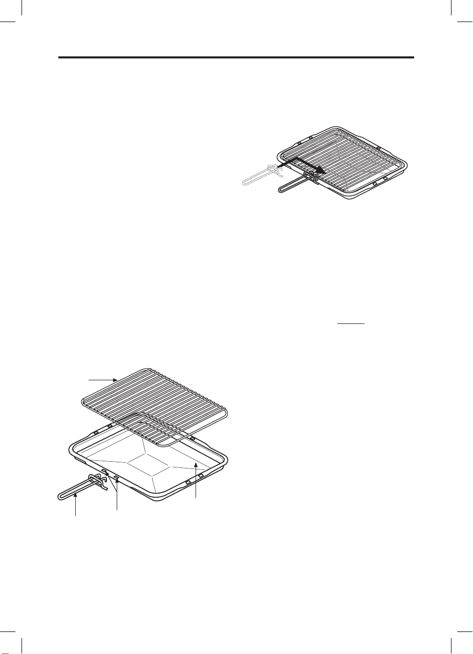
Detachable grill pan handle
Place the handle over the edge of the grill
pan, at the narrow side edges. Slide the
handle to the centre, and locate between
the handle position indicators.
The handle should be removed from
the pan during grilling, to prevent
overheating.
The handle is designed for removing/
inserting the grill pan under the grill when
grilling.
If cleaning the grill pan when it is hot, use
oven gloves to move it. Do not use the
handle to pour hot fats from the grill pan.
Food for grilling should be positioned
centrally on the trivet.
Preheating
For best cooked results, always preheat
the grill for about 3 minutes.
USING THE GRILL
Caution: Accessible parts may
be hot when the grill is used.
Young children should be kept
away.
Ignition
Important: Keep the grill door open
when the grill is on.
To turn off, push in the control knob
and turn it clockwise to the “off”position.
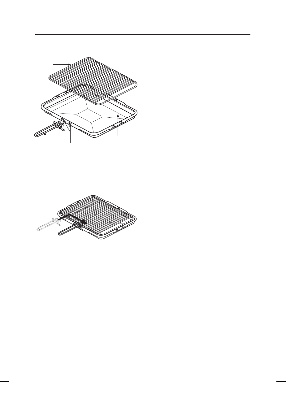
Detachable grill pan handle
Place the handle over the edge of the
grill pan, at the narrow side edges.
Slide the handle to the centre, and
locate between the handle position
indicators.
The handle should be removed from
the pan during grilling, to prevent
overheating.
The handle is designed for removing /
inserting the grill pan under the grill
when grilling.
If cleaning the grill pan when it is hot,
use oven gloves to move it. Do not use
the handle to pour hot fats from the
grill pan.
Food for grilling should be positioned
centrally on the trivet.
Preheating
For best cooked results, always
preheat the grill for about 3 minutes.
handle
grill pan
grid
handle position
indicators
Open the grill door.
Push in and turn the grill control knob
anticlockwise to the “full-on” position.
Hold the control knob in for 15 seconds
and press the ignition switch (if fitted),
or hold a lighted match or taper to the
burner, until the burner lights.
Do not hold the control knob in for
longer than 15 seconds. If the burner
fails to light within this time, release the
control knob and wait for one minute
before attempting further ignition.
Page 7

USING THE GRILL - GAS
Aluminium foil
Using aluminium foil to cover the grill
pan, or putting items wrapped in foil
under the grill creates a fire hazard.
Using the grill
Push the grill pan towards the back of the
shelf, to position it under the grill.
Variation in grilling can be achieved by
setting the grill between the large and
small flame symbols.
Important: Never operate the grill between
the large flame and the off position.
The speed of grilling can also be
controlled by selecting a higher or lower
shelf position.
For toasting, and for grilling foods such as
bacon, sausages or steaks,use a higher
shelf position.
For thicker foods such as chops or chicken
joint pieces, use a middle to low shelf
position.
The grill trivet, inside the grill pan, can be
inverted to give a high or low position, or
it may be removed.
When you have finished grilling, check
that the control knob is returned to the off
position.
The cooling fan
When the grill is switched on, you will hear
the cooling fan come on this keeps the
fascia and control knobs of the appliance
cool during grilling. The fan may continue
to operate for a period after the grill
control has been switched off.
During oven use the fan may cycle on and
off. Should any fault occur with the cooling
fan, the appliance will require servicing.
Contact Customer Support.
Page 8

USING THE GRILL - ELECTRIC (IN A GAS PRODUCT)
Caution: Accessible parts may be hot when
the grill is used - young children should be
kept away.
Open the top oven / grill door. Push in
and turn the top oven / grill control knob
clockwise to the ‘FULL ON’ position.
To switch off, turn the control knob
antclockwise to return it to the off position.
Important: The top oven / grill doormust
be fully open when the grill is used.
Preheating
For best cooked results, we recommend
that you preheat the grill for about 3
minutes.
The cooling fan
When the grill is switched on, you will hear
the cooling fan come on this keeps the
fascia and control knobs of the appliance
cool during grilling. The fan may continue
to operate for a period after the grill
control has been switched off.
During oven use the fan may cycle on and
off. Should any fault occur with the cooling
fan, the appliance will require servicing.
Contact Customer Support.
Page 9
USING THE GRILL - ELECTRIC (IN A GAS PRODUCT)
Detachable grill pan handle
Place the handle over the edge of the grill
pan, at the narrow side edges. Slide the
handle to the centre, and locate between
the handle position.
The handle should be removed from
the pan during grilling, to prevent
overheating. The handle is designed for
removing / inserting the grill pan under
the grill when grilling.
If cleaning the grill pan when it is hot, use
oven gloves to move it. Do not use the
handle to pour hot fats from the grill pan.
Food for grilling should be positioned
centrally on the trivet.
Using the grill
Push the grill pan towards the back of the
shelf, to position it under the grill.
The speed of grilling can be controlled by
selecting a higher or lower shelf position.
For toasting, and for grilling foods such as
bacon, sausages or steaks, use a higher
shelf position.
For thicker foods such as chops or chicken
joint pieces, use a middle to low shelf
position.
The grill trivet, inside the grill pan, can be
inverted to give a high or low position, or
it may be removed.
The HIGH trivet position is suitable
fortoasting bread.
The LOW trivet position is suitable
forgrilling all types of meat & fish.
With the grill trivet removed the food is
placed directly on the base of the grill
pan - eg: when cooking whole fish or
browning dishes such as cauliflower
cheese.
When you have finished grilling, check that
the control knob is returned to the off position.
Using aluminium foil
Using aluminium foil to cover the grill
pan, or putting items wrapped in foil
under the grill creates a fire hazzard.
USING THE GRILL
Detachable grill pan handle Using the grill
Push the grill pan towards the back of
the shelf, to position it under the grill.
The speed of grilling can be controlled
by selecting a higher or lower shelf
position.
For toasting, and for grilling foods
such as bacon, sausages or steaks,
use a higher shelf position.
For thicker foods such as chops or
chicken joint pieces, use a middle to
low shelf position.
handle
grill pan
grid
handle position
indicators
USING THE GRILL
Detachable grill pan handle Using the grill
Place the handle over the edge of the
grill pan, at the narrow side edges.
Slide the handle to the centre, and
locate between the handle position.
Push the grill pan towards the back of
the shelf, to position it under the grill.
The speed of grilling can be controlled
by selecting a higher or lower shelf
position.
For toasting, and for grilling foods
such as bacon, sausages or steaks,
use a higher shelf position.
For thicker foods such as chops or
chicken joint pieces, use a middle to
low shelf position.
The grill trivet, inside the grill pan, can
be inverted to give a high or low
position, or it may be removed.
The HIGH trivet position is suitable for
toasting bread.
The LOW trivet position is suitable for
grilling all types of meat & fish.
With the grill trivet removed the food is
handle
grill pan
grid
handle position
indicators
Page 10

USING THE MAIN OVEN - GAS
Using the main oven
Ignition
Push in and turn the main oven control
knob to the ‘FULL ON’ position (gas mark
9). Hold the control knob in, and press the
ignition switch or hold a lighted match or
taper to the burner, until the burner lights.
If after 15 seconds, the burner has
not lit, turn off the oven and leave the
compartment door open. Wait at least one
minute before a further attempt to ignite
the burner.
Do not hold the control knob in for more
than 15 seconds.
Turn the control knob to the required
setting.
To turn off, return the control knob to the
“off” position.
Preheat the main oven for 15 minutes.
If you are not preheating the oven, the
cooking times in the baking guides may
need to be extended, as they are based on
a preheated oven.
The oven must be preheated when
reheating frozen or chilled foods, and we
recommend preheating for yeast mixtures,
batters, soufflés and whisked sponges.
Put the oven shelves in the position
required before preheating the oven.
Oven light
Press the light button on the facia panel.
Zones of heat
The temperature at the centre of the oven
corresponds with the selected gas mark
and is slightly higher towards the top of
the oven and slightly lower towards the
oven base.
These zones of heat can be useful
as different dishes requiring different
temperatures can be cooked at the same
time, when more than one shelf is used.
The temperature at the oven base is
suitable for cooking baked vegetables,
baked fruit, milk pudding etc, and for
warming bread rolls, soup, coffee, or
ovenproof plates and dishes.
If you find that over a period of time,
the oven becomes hotter when used at a
particular gas mark, the thermostat may
need to be replaced.
Oven furniture
Baking tray and roasting tins
For best cooked results and even
browning, the maximum size baking trays
and roasting tins that should be used are
as follows;
Baking tray 350mm x 330mm
Roasting tin 370mm x 320mm
Position baking trays and roasting tins on
the middle of the shelves, and leave one
clear shelf position between shelves, to
allow for circulation of heat.
Oven shelves
Extra shelves may be ordered from your
local supplier.
The oven shelf must be positioned with the
upstand at the rear of the oven and facing
upwards.
Slow cooking
Make sure that frozen foods are
thoroughly THAWED before cooking.
Do not slow cook joints of meat or poultry
weighing more than 2¼kg / 4½lb.
Always use the top half of the oven for
slow cooking.
Page 11
USING THE MAIN OVEN - GAS
For roasting joints of meat or poultry, and
for pot roasts preheat the oven to gas
mark 6 and cook for 30 minutes, then
adjust the oven control to the “S” slow
setting for the remainder of the cooking
time.
Slow cooking times will be about three
times as long as conventional cooking
times.
Main oven baking guide
Dish Recommended
gas mark
Suggested shelf
position
Approximate
cooking time
(preheated oven)
Scones
Meringues
7
“S” slow set
middle - top
bottom
8 - 15 mins
2 - 3 hours
Cakes
Small cakes
Whisked sponge
Swiss roll
Victoria sandwich
(2 x 180mm / 7”)
Genoese sponge
Madeira (180mm / 7”)
Gingerbread
Semi rich fruit cake
(205mm / 8”)
Christmas cake
(205mm / 8”)
Dundee cake (205mm / 8”)
5
5
6
4
4
3
3
2 or 3
1 or 2
3
middle - top
middle - top
middle - top
middle - top
middle
middle
middle
middle - top
bottom
middle - bottom
15 - 25 mins
20 - 25 mins
10 - 12 mins
20 - 30 mins
20 - 30 mins
1 - 1¼ hours
1 - 1¼ hours
2½ - 3 hours
depending on
recipe
2 - 2½ hours
Pastry
Rough Puff
Flaky / Puff
Shortcrust
Flan
7
6
6
6
middle - top
middle - top
middle - top
middle - top
Cooking time
depends on
recipe and type
of filling
Biscuits
Nut brownies
Brandy snaps
Flapjacks
Gingernuts
5
4
4
4
middle - top
middle - top
middle - top
middle - top
25 - 35 mins
10 - 12 mins
20 - 25 mins
10 - 20 mins
Page 12

USING THE MAIN OVEN - GAS
Traditional fruit cakes
It should be remembered that ovens can
vary over time, therefore cooking times
can vary, making it difficult to be precise
when baking fruit cakes.
It is necessary therefore, to test the cake
before removal from the oven. Use a fine
warmed skewer inserted into the centre of
the cake. If the skewer comes out clean,
then the cake is cooked.
• Do not attempt to make Christmas
cakes larger than the oven can cope with,
you should allow at least 25mm (1 inch)
space between the oven walls and the tin.
• Always follow the temperatures
recommended in the recipe.
• To protect a very rich fruit cake during
cooking, tie 2 layers of brown paper
around the tin.
• We recommend that the cake tin is not
stood on layers of brown paper, as this
can hinder effective circulation of air.
• Do not use soft tub margarine for rich
fruit cakes, unless specified in the recipe.
• Always use the correct size and shape
of tin for the recipe quantities.
Roast turkey
Roasting turkey involves cooking two
different types of meat - the delicate light
breast meat, which must not be allowed
to dry out, and the darker leg meat, which
takes longer to cook.
The turkey must be roasted long enough
for the legs to cook, so frequent basting
is necessary. The breast meat can be
covered once browned.
• Always make sure that the turkey is
completely thawed and that the giblets are
removed before cooking.
• Turkey should be roasted at gas mark
5 for 20 minutes per lb, plus 20 minutes,
unless packaging advises otherwise.
• The turkey can be open roasted,
breast side down, for half of the cook
time, and then turned over for the
remainder of the cooking time.
• If the turkey is stuffed, add 5 minutes
per lb to the cooking time.
• If roasting turkey covered with foil, add
5 minutes per 1lb to the cooking time.
To test if the turkey is cooked, push a fine
skewer into the thickest part of the thigh. If
the juices run clear, the turkey is cooked. If
the juices are still pink, the turkey will need
longer cooking.
Page 13

USING THE MAIN OVEN - GAS
Roasting guide
The times given in the roasting guide are
only approximate, because the size and
age of the bird will influence cooking
times as will the shape of a joint and the
proportion of the bone.
Frozen meat should be thoroughly thawed
before cooking. For large joints it is
advisable to thaw over night.
Frozen poultry should be thoroughly
thawed before cooking. The time required
depends on the size of the bird - eg; a
large turkey may take up to 48 hours to
thaw.
Use of a trivet with a roasting tin will
reduce fat splashing and will help to keep
the oven interior clean. Alternatively, to
help reduce fat splashing, potatoes or
other vegetables can be roasted around
the meat / poultry.
Notes:
• When cooking stuffed meat or poultry
calculate the cooking time from the total
weight of the meat plus the stuffing.
• For joints cooked in foil or covered
roasters, and for lidded casseroles, add 5
minutes per 450g (1lb) to the calculated
cooking time.
• Smaller joints weighing less than
1.25kg (2½lb) may require 5 minutes per
450g (1lb) extra cooking time.
• Position the oven shelf so that the meat
or poultry is in the centre of the oven.
• It is recommended that the appliance
is cleaned after open roasting.
Cook in oven at Gas Mark 5 Approximate Cooking Time
(preheated oven)
Beef Rare
Medium
Well done
20 minutes per 450g (1lb), plus 20 minutes
25 minutes per 450g (1lb), plus 25 minutes
30 minutes per 450g (1lb), plus 30 minutes
Lamb Medium
Well Done
25 minutes per 450g (1lb), plus 25 minutes
30 minutes per 450g (1lb), plus 30 minutes
Pork 35 minutes per 450g (1lb), plus 35 minutes
Poultry 20 minutes per 450g (1lb), plus 20 minutes
Page 14

USING THE MINUTE MINDER (if fitted)
The digital timer enables you to set the
time of day (24 hour clock) and the minute
minder alarm.
Setting the “Time of Day”
1. Switch on the electricity supply to the
appliance.
The display will flash.
2. Press and release the time of day
button.
3. Set the time of day with the plus and
minus buttons.
4. The time will be set 7 seconds after the
last plus or minus operation.
Alarm tones
After setting the time of day, you can select
one of three alarm tones.
Press the minus button to listen to the first
tone, then release the minus button and
press it again to listen to the second tone,
etc.
Releasing the minus button after a tone
has sounded will automatically select that
tone.
Setting the minute minder
1. Press and release the plus button to
change the display from clock to minute
minder - the bell symbol will light.
2. Use the plus and minus buttons to set
the length of time before the alarm tone
will sound. The display will increase /
decrease in units of 10 seconds up to 99
minutes 50 seconds, and in units of 1
minute from 1 hour 40 minutes upwards.
The maximum period which may be set is
10 hours.
The display format will change after 99
minutes and 50 seconds to 1 hour and 40
minutes.
During countdown, the minute minder has
priority on the display, which will show (in
minutes : seconds, or hours : minutes) the
time remaining.
When countdown is complete, the tone will
sound for 7 minutes, or it can be reset with
one touch of any button.
To cancel the minute minder at any other
time, run down the set time with the minus
button.
The display will revert to show the time of
day.
Minute Minder (if fitted)
Initial display
Setting the minute minder
1. Press and release the plus button
to change the display from clock
to minute minder - the bell symbol
will light.
2. Use the plus and minus buttons to
set the length of time before the
alarm tone will sound. The display
will increase / decrease in units of
10 seconds up to 99 minutes 50
seconds, and in units of 1 minute
Use to set
the correct time
Minus
button
Plus
button
Function
select
Press &
release:
to set
the time
Page 15

CLEANING
GENERAL
• It is important to clean the product
regularly as a build up of fat can affect
its performance or damage it and may
invalidate your guarantee.
• Always switch off your appliance and
allow it to cool down before you clean any
part of it.
• Do not use undiluted bleaches,
products containing chlorides, wire wool,
abrasive cleaners or nylon pads.
• Take extra care when cleaning over
symbols on fascia panels. Excessive
cleaning can lead to the symbols fading.
Painted & Plastic parts
• Only use a clean cloth wrung out in
hot soapy water.
• Do not use abrasive cleaners, such
as “Cif”, wire or nylon cleaning pads on
these parts.
Stainless steel & Aluminium surfaces
• Only use a clean cloth wrung out in
hot soapy water, and dry with a soft cloth.
• Stubborn marks can be removed using
a stainless steel cleaner. Supplies can
be purchased from the Customer Care
Centre.
• Sharp objects can mark the surface
of stainless steel, but will become less
noticeable with time.
• Wipe any spillage immediately, taking
care to avoid burning your hands.
• Some foods are corrosive eg; vinegar,
fruit juices and especially salt - they can
mark or damage the metal if they are left
on the surface.
• Baby oil can be used to restore
stainless steel finishes - but only use a few
drops. Don’t use cooking oils as they
can contain salts, which will damage the
metal.
• Do not use steam cleaners.
Enamel surfaces & parts
• Clean with warm, soapy water and a
clean cloth.
• If larger splashes of fat do not readily
disappear, you can use a mild cream
cleaner to remove them. More stubborn
marks can be removed using a soap filled
pad.
• Rinse well and dry with a soft clean
towel or cloth.
• Do not use steam cleaners.
Glass parts
• Only use a clean cloth wrung out
in hot soapy water, or a specialist glass
cleaner.
• Rinse away any excess cleaner and dry
with a soft cloth.
• Do not use abrasives or polishes as
they will scratch and damage the glass.
Chrome plated parts
• Use a moist soap filled pad, or place
in a dishwasher.
REMOVING OVEN PARTS FOR CLEANING
Inner Door Glass
• The inner door glass panel can be
removed for cleaning but it must be
replaced the right way up. If there is any
writing on the glass, you must be able to
read it clearly when the cavity doors are
open.
• Always make sure that the glass is
pushed fully into the Stop position.
• To remove the glass panel, open the
door wide, hold the top and bottom edges
and slide out.
Page 16

CLEANING
• Warning: DO NOT operate the appliance
without the glass panel correctly fitted.
• For your safety, glass door panels are
made of toughened glass. This ensures
that, in the unlikely event that a panel
breaks, it does so into small fragments to
minimise the risk of injury. Please take care
when handling, using or cleaning all glass
panels, as any damage to the surfaces
or edges may result in the glass breaking
without warning or apparent cause at
a later date. Should any glass panel be
damaged, we strongly recommend that it
is replaced immediately.
Shelf Runners
• Shelf runners can be removed to
enable you to clean then thoroughly.
Make sure they are cool to touch and then
grasp the runners and slide out of their
hanging holes.
Page 17

INSTALLATION INSTRUCTIONS
Before you start: Please read the
instructions. Planning your installation will
save you time and effort.
Prior to installation, ensure that the local
distribution conditions (nature of the gas
and gas pressure) and the adjustment
of the appliance are compatible. The
adjustment conditions are stated on the
data badge.
This appliance is not connected to a
combustion evacuation device. It shall be
installed and connected in accordance
with current installation regulation.
Particular attention shall be given to
the relevant requirements regarding
ventilation.
In your own interest and that of safety, it is
the law that all gas appliances be installed
and serviced by competent persons. Gas
Safe registered installers undertake to
work to satisfactory standards.
Where regulations or standards have been
revised since this handbook was printed,
always use the latest edition.
In the UK the regulations and standards are
as follows:
1. Gas Safety Regulations (Installation
and Use).
2. Building Regulations - Issued by the
Department of the Environment.
3. Building Standards (Scotland)
(Consolidated) - Issued by the Scottish
Development Department.
4. The current I.E.E. Wiring Regulations.
5. Electricity at Work Regulations.
6. BS 6172 Installation of Domestic Gas
cooking Appliances
7. Installation & Servicing Instructions for
this appliance.
For installation in countries other than the
UK, the appliance must be connected in
accordance with all local gas and
electrical regulations. In the Republic of
Ireland, Installers should refer to IS813
Domestic Gas Appliances.
Ventilation Requirements
The room containing the appliance should
have an air supply in accordance with BS
5440: Part 2.
• All rooms require an openable
window, or equivalent, and some
rooms will require a permanent vent
as well.
• For room volumes up to 5m3 an air
vent of 100cm2 is required.
• If the room has a door that opens
directly to the outside, or the room
exceeds 10m3, NO AIR VENT is
required.
• For room volumes between 5m3 and
10m3 an air vent of 50cm2 is
required.
• If there are other fuel burning
appliances in the same room, BS
5440: Part 2 should be consulted to
determine the air vent requirements.
• This appliance must not be installed in
a bed sitting room of less than 20m3
or in a bathroom or shower room.
Windows and permanent vents should
therefore not be blocked or removed
without first consulting a Gas Safe gas
installer.
In the Republic of Ireland, refer to relevant
Irish Standards for correct ventilation
requirements.
Failure to install appliances correctly is
dangerous and could lead to prosecution.
This appliance is not connected to a
combustion products evacuation device.
It shall be installed and connected in
accordance with current installation
regulations. Particular attention shall
be given to the relevant requirements
regarding ventilation.
Page 18

INSTALLATION INSTRUCTIONS - 60CM
Step 1: Prepare installation
Do not lift the appliance by the door handle.
Whilst every care is taken to eliminate
burrs and raw edges from this product,
please take care when handling - we
recommend the use of protective gloves
during installation.
Please note that the weight of this
appliance is approximately 31kg
(unpacked). Take care when lifting it
into the housing unit - always use an
appropriate method of lifting.
Remove the fixing screws from the
polythene bag on the top of the appliance,
but leave the appliance in the base tray
packaging until you are ready to install it.
If this appliance is to be installed near to
a corner where the adjacent cabinets run
at right angles forward of the appliance,
there must be a gap of at least 90 mm
between the appliance and the cabinets,
to prevent overheating of the cabinets.
Housing dimensions
The appliance is designed to fit into a
standard 600mm wide housing unit with
minimum internal dimensions as shown.
591mm is to the underside of the worktop
when the appliance is built under, or to the
underside of the panel above, when the
appliance is installed into a tall housing
unit.
Housing dimensions
The appliance is designed to fit into a
standard 600mm wide housing unit
with minimum
internal dimensions as
shown.
591mm is to the underside of the
worktop when the appliance is built
under, or to the underside of the panel
above, when the appliance is installed
into a tall housing unit.
585
mm
min
560mm
595mm
550mm
568
mm
547mm
20mm
min 550mm
30 - 80mm
min
580
mm
min
590
mm
12mm
gap in plinth
6mm
588
mm
90mm (minimum)
Installation Instructions
90mm (minimum)
Page 19

INSTALLATION INSTRUCTIONS - 60CM
i) When installed in a typical 600mm
deep built in housing unit, the false
back should be removed from the
housing unit to provide the necessary
depth for installation.
ii) When the false back is removed, it is
normally the case that the support
shelf for the appliance leaves a gap
between the back edge and the wall of
approximately 80mm.
iii) If no gap occurs between the back
edge of the shelf and the wall behind
the unit, we recommend that a gap of
at least 30mm is made by shortening
the shelf.
iv) When installing the appliance below a
worktop, there must be a minimum
ventilation area of 60cm2 below the
appliance, in either area (1) or (2), as
indicated below. There must be a
5mm gap between the front top edge
of the oven and the underside of the
worktop.
Important: Do not modify the outer panels
of this appliance in any way.
Ensure that you route all mains electrical
cables and flexible tubing well clear of any
adjacent heat source, such as an oven,
grill or hob.
Ensure that all pipe work is of the correct
rating for both size and temperature.
Installing the appliance under a worktop
Where the appliance is installed under
a worktop, with a hob installed above it,
the installation instructions for the hob
must be read in conjunction with these
instructions.
2
Important: Do not
modify the outer
panels of this appliance in any way.
Ensure that you route all mains
electrical cables and flexible tubing
well clear of any adjacent heat source,
such as an oven, grill or hob.
Ensure that all pipe work is of the
correct rating for both size and
temperature.
Installing the appliance under a
worktop
Where the appliance is installed under
a worktop, with a hob installed above
it, the installation instructions for the
hob must be read in conjunction with
these instructions.
worktop
support shelf
rear wall
front
of oven
5 mm
30 - 80
mm
minimum
ventilation
area 60 cm
2
(1)
(2)
Installation Instructions
Page 20

INSTALLATION INSTRUCTIONS - 70CM
Before you start - please read the
instructions carefully - planning your
installation will save you time and effort.
Look at the different ways the appliance
can be installed - as shown on the
following pages - and plan the installation
to suit your situation.
Leave the appliance in the base tray
packaging until you are ready to install
it. When you remove the appliance from
the base tray packaging, take care not to
damage it.
Whilst every care is taken to eliminate
burrs and raw edges from this product,
please take care when handling - we
recommend the use of protective gloves
during installation.
Please note that the weight of this
appliance is approximately 47kg
(unpacked). Take care when lifting it
into the housing unit - always use an
appropriate method of lifting.
This appliance must be installed only
at low level - ie; under a worktop. The
controls have been designed for viewing
at a low level, and it should therefore not
be installed at high level.
Please note that all dimensions and sizes
given are nominal, some variation is to be
expected.
If this appliance is to be installed near to
a corner where the adjacent cabinets run
at right angles forward of the appliance,
there must be a gap of at least 90mm
between the appliance and the cabinets,
to prevent overheating of the cabinets.
Important: Do not modify the outer panels
of this appliance in any way.
Fixing screws - The fixing screws are
in a polythene bag in the oven pack.
Depending on the method of installation,
some of the screws may not be needed.
Step 1: Prepare for installation
There are 3 methods of installing the
appliance:
Method 1: Into a space between two base
units, ie; without a housing unit.
Method 2: Into a housing unit, with an
internal height of less than 710mm, which
can be modified to obtain the required
dimensions.
Method 3: Into a housing unit, with an
internal height of 710mm or more. If
you have a non standard size of cabinet
which leaves a gap above or below the
appliance, you may be able to buy a trim
kit (to fill in the gap) from the supplier of
your cabinets.
Quantity Colour Description For Fixing
6 Silver No 8 x 12mm long Self
tapping screw
Runners to appliance
12 Black No 8 x 12mm long
Chipboard screw
Runners and sidetrims
to cabinet or housing
6 Black No 8 x 25mm long
Chipboard screw
Appliance to cabinet
2 Silver No 8 x 12mm long Self
tapping screw
Appliance to sidetrims
Page 21

INSTALLATION INSTRUCTIONS - 70CM
Method 1: Without housing unit
(between 2 base units)
Before installing the appliance, check the
internal dimensions as shown.
The space for the appliance must be clear
of obstruction. You may have to cut into or
remove any rear cross members to obtain
the 550mm minimum depth.
The Fixing Kit
Should you need a replacement fixing kit
please call the customer care helpline and
order part number: 01 28287 00.
In the fixing kit you will find 2 side trims
(687mm long) and 4 runners (420mm
long). The fixing screws are in a polythene
bag in the oven.
1. Take the 6 No 8 x 12mm (silver) self
tapping screws from the polythene
bag, and use them to fit one runner to
each side of the appliance.
2. Make sure they are the right way up as
shown.
3. Take one of the side trims, hold it
against the side of the base unit, and
mark off 687mm from the top edge of
the base unit, to the top edge of the
runner.
Note: This ensures a 5 - 8mm
clearance from the underside of the
worktop to the top of the appliance.
4. Measure 50mm from the front edge of
the base units, to mark the front edge
of the runners.
5. Take 6 of the No 8 x 12mm (Black)
chipboard screws and screw the
runners into opposition the right way
up as shown.
6. Fit the side trims to be flush to the top
and front edges of the base units,
using the remaining 6 No 8 x 12mm
(Black) chipboard screws.
Page 22

INSTALLATION INSTRUCTIONS - 70CM
Method 1: Without housing unit (between 2 base units)
Shown with fixing kit
Installation Instructions
Method 1: Without housing unit (between 2 base units)
Shown with fixing kit
min 550mm
598-602mm
710mm
runners
50mm
side trim
687
mm
Page 23

INSTALLATION INSTRUCTIONS - 70CM
Method 1: Without housing unit (between 2 base units)
Shown without fixing kit
Method 1: Without housing unit (between 2 base units)
Shown without fixing kit
Installation Instructions
min 550mm
598-602mm
side trim
Page 24

INSTALLATION INSTRUCTIONS - 70CM
Method 2: Housing unit with
internal height less than 710mm.
Note: You will not need the 2 side trims
(687mm long) or the appliance runners
for this installation. You will need the 2
runners to fix to the adjacent cabinets.
Before you start;
Before removing the bottom shelf or
modifying the housing unit, make sure
that it will remain structurally sound, eg;
by fixing to adjacent cabinets, floor or
worktop.
You may have to cut into or remove any
rear cross members to obtain the 550mm
minimum depth.
To obtain the required 710mm height,
you may have to lower or remove the
bottom shelf - remove any cross rails and
reposition brackets.
To fix the runners (if required)
1. Take the side trims, hold it against
the side of the base unit, and use it to
mark off the 687mm from the top
edge of the side unit, to the top edge
for the runner.
Note: This ensures a 5 - 8mm
clearance from the underside of the
worktop to the top of the appliance.
2. Measure 50mm from the front edges
of the base units, to mark the front
edge for the runners.
3. Take 6 of the No 8 x 12mm (Black)
chipboard screws and screw the
runners into position the right way up
as shown.
4. If necessary, adjust the height of the
plinth to just below the bottom edge of
the runners.
If you require a replacement fixing kit
please call the customer care helpline and
order part number 01 28287 00.
Page 25

INSTALLATION INSTRUCTIONS - 70CM
Method 2: Housing unit with internal height less than 710mm
Shown with fixing kit
Installation Instructions
Method 2: Housing unit with internal height less than 710mm
Shown with fixing kit
min 550mm 560-570mm
710mm
687
mm
runners
50mm
Page 26

INSTALLATION INSTRUCTIONS - 70CM
Method 2: Housing unit with internal height less than 710mm
Shown without fixing kit
Method 2:
Housing unit with internal height less than 710mm
Shown without fixing kit
Installation Instructions
min 550mm
560-570mm
Page 27

INSTALLATION INSTRUCTIONS - 70CM
Method 3: Housing unit with internal height
710mm or more
Note: You will not need the 4 runners and
2 trims that are packed with the oven for
this installation.
1. When installed in a typical 600mm
deep built in housing unit, the false
back should be removed from the
housing unit to provide the necessary
depth for installation.
2. When the false back is removed, it is
normally the case that the support
shelf for the appliance leaves a gap
between the back edge and the wall of
approximately 80mm.
3. If no gap occurs between the back
edge of the shelf and the wall behind
the unit, you must create a gap of at
least 30mm by shortening the shelf.
Remove any fixings that may prevent
entry of the oven into housing, or obstruct
the gas inlet pipe. The cabinetry should
be kept structurally sound by fixing to
adjacent cabinets, floor or worktop.
Method 3: Housing unit with internal
height 710mm or more
Note: You will not need the 4 runners
and 2 trims that are packed with the
oven for this installation.
Remove any fixings that may prevent
entry of the oven into housing, or
obstruct the gas inlet pipe. The
cabinetry should be kept structurally
sound by fixing to adjacent cabinets,
floor or worktop.
1. When installed in a typical
600mm deep built in housing unit,
the false back should be removed
from the housing unit to provide
the necessary depth for installation.
2. When the false back is removed,
it is normally the case that the
support shelf for the appliance leaves
a gap between the back edge and
the wall of approximately 80mm.
3. If no gap occurs between the back
edge of the shelf and the wall
behind the unit, you must create a
gap of at least 30mm by
shortening the shelf.
Installation Instructions
595mm
703mm
9mm
706
mm
547mm
697
mm
560-570mm
min 550mm
min
710
mm
12mm gap in
plinth for air intake
550mm
Worktop
Rear
wall
space behind
appliance to
be kept clear
12mm gap in
plinth for air intake
12mm air
gap in top
of plinth
support
shelf
Page 28

INSTALLATION INSTRUCTIONS - 90CM
Step 1: Prepare installation
Do not lift the appliance by the door handle.
Remove the fixing screws from the
polythene bag on the top of the appliance,
but leave the appliance in the base tray
packaging until you are ready to install it.
Whilst every care is taken to eliminate
burrs and raw edges from this appliance,
please take care when handling - we
recommend the use of protective gloves
during installation.
Please note that the weight of this
appliance is approximately 48kg
(unpacked). Take care when lifting it
into the housing unit - always use an
appropriate method of lifting.
Note: When removing the appliance from
the base tray packaging care should
be taken to ensure the appliance is not
damaged.
Siting the appliance
If this appliance is to be installed near to
a corner where the adjacent cabinets run
at right angles forward of the appliance,
there must be a gap of at least 90mm
between the appliance and the cabinets,
to prevent overheating of the cabinets.
When installed in a typical 600mm
deep built in housing unit, the false back
should be removed from the housing
unit, to provide the necessary depth for
installation.
When the false back is removed, it is
normally the case that the support shelf
for the appliance leaves a gap between
the back edge of the support shelf and the
rear wall of approximately 80mm.
If no gap occurs between the back edge
of the shelf and the wall behind the unit,
you must create a gap of at least 30mm
by shortening the shelf and any other shelf
below the appliance.
Cut 12mm from the top of any plinth that
may be fitted (see diagram).
Important: Do not modify the outer
panels of this appliance in any way.
When the false back is removed, it is
normally the case that the support shelf
for the appliance leaves a gap
between the back edge of the support
shelf and the rear wall of
approximately 80mm.
If no gap occurs between the back
edge of the shelf and the wall behind
the unit, you must create a gap of at
least 30mm by shortening the shelf
and any other shelf below the appliance.
Cut 12mm from the top of any plinth
that may be fitted (see diagram).
Important: Do not modify the outer
panels of this appliance in any way.
Page 29

INSTALLATION INSTRUCTIONS - 90CM
Dimensions
The appliance is designed to fit into a
standard 600mm wide housing unit, with
minimum internal dimensions as shown.
Note: All sizes are nominal, some
variation is to be expected.
Dimensions
The appliance is designed to fit into a
standard 600mm wide housing unit,
with minimum internal dimensions as
shown.
Note: All sizes are nominal, some
variation is to be expected.
INSTALLATION INSTRUCTIONS
Page 30

INSTALLATION INSTRUCTIONS
Step 2: Connect to gas supply
1. The inlet to the appliance is ISO 7
- Rp ½” internal thread situated
towards the top right hand rear corner.
2. Fit the bayonet connection to the wall
in the shaded area as shown.
The shaded area shown is applicable to
installations in minimum depth cabinets.
If more room is available, the bayonet
fixing area can be extended, provided that
the flexible tube does not obscure the fan
intake.
3. Use a 900mm - 1125mm length of
flexible connector. The flexible
connector shall be fitted such that it
cannot come into contact with a
moveable part of the housing unit (eg;
drawer) and does not pass through
any space susceptible of becoming
congested. Make sure that the flexible
connector does not block the cooling
fan inlet.
4. Flexible connections should comply
with BS 669. Parts of the appliance
likely to come into contact with a
flexible connector have a temperature
rise of less than 70°C.
5. Rigid connections must be accessible
to disconnect for servicing. Cut a
150mm square hole in the right hand
rear corner of the support shelf for the
supply pipe.
6. Make sure all connections are gas
sound.
- Rp
1
⁄2” internal thread situated
towards the top right hand rear
corner.
wall in the shaded area as shown.
The shaded area shown is
applicable to installations in
minimum depth cabinets.
If more room is available, the
bayonet fixing area can be
extended, provided that the
flexible tube does not obscure the
fan intake.
4. Flexible connections should
comply with BS 669. Parts of the
appliance likely to come into
contact with a flexible connector
have a temperature rise of less
than 70˚C.
5. Rigid connections must be accessible
to disconnect for servicing. Cut a
150mm square hole in the right
hand rear corner of the support
shelf for the supply pipe.
6. Make sure all connections
are gas sound.
Installation Instructions
60mm
60
mm
60mm
square
rear
wall
Page 31

INSTALLATION INSTRUCTIONS
Step 3: Connect to the electricity supply
This appliance must be connected by a
competent person, using fixed wiring via
a double pole switched fused spur outlet,
with a contact separation of 3mm at all
poles.
Use a 13 amp fuse.
We recommend that the appliance is
connected by a qualified electrician,
who will comply with the I.E.E. and local
regulations.
Warning: This appliance must be earthed.
The wires in the mains lead are coloured
in accordance with the following code:
Green & Yellow = earth, Blue = neutral,
Brown = live.
Typical example of a double pole fuse spur
outlet
As the colours of the wires in the mains
lead for the appliance may not correspond
with the coloured markings identifying the
terminals in your spur box, proceed as
follows:
1. The wire which is coloured green and
yellow must be connected to the
terminal marked E (Earth)
or coloured green.
2. The wire which is coloured blue must
be connected to the terminal marked
N (Neutral) LOAD or coloured Black.
3. The wire which is coloured brown must
be connected to the terminal marked L
(Live) LOAD or coloured Red.
If the supply cord is damaged, obtain a
special cord from the Customer Support
Helpline, which must be fitted by a
qualified person.
Step 3: Connect to the electricity
supply
This appliance must be connected by
a competent person, using fixed
wiring via a double pole switched
fused spur outlet, with a contact
separation of 3mm at all poles.
Use a 13 amp fuse.
We recommend that the appliance is
connected by a qualified electrician,
who will comply with the I.E.E. and
local regulations.
Warning: This appliance must be
earthed.
The wires in the mains lead are
coloured in accordance with the
following code: Green & Yellow =
earth, Blue = neutral, Brown = live.
As the colours of the wires in the mains
lead for the appliance may not
correspond with the coloured markings
identifying the terminals in your spur
box, proceed as follows:
1. The wire which is coloured green
and yellow must be connected to
the terminal marked E (Earth) or
coloured green.
2. The wire which is coloured blue
must be connected to the terminal
marked N (Neutral)
LOAD or
coloured Black.
3. The wire which is coloured brown
must be connected to the terminal
marked L (Live)
LOAD or coloured
Red.
If the supply cord is damaged, obtain
a special cord from the Customer
Support Helpline, which must be fitted
by a qualified person.
Installation Instructions
USE A 13 AMP FUSE
FUSE
ON
Typical example of a double
pole fuse spur outlet
Live
Earth
Neutral
Cable
N LOAD
LOAD L
N SUPPLY L
13
250
~
Page 32

INSTALLATION INSTRUCTIONS - 60/90CM
Step 4: Secure appliance into housing unit
There are 4 black no 8 x 25mm long
chipboard screws for securing appliance
to cabinet.
Insert appliance into cabinet and secure
- open the oven door and screw the 4
screws through the holes in the front
frame.
Note: The unit housing the appliance must
be appropriately fixed.
Installation Instructions
Step 4: Secure appliance into
housing unit
There are 4 black no 8 x 25mm long
chipboard screws for securing
appliance to cabinet.
Insert appliance into cabinet and
secure - open the oven door and screw
the 4 screws through the holes in the
front frame.
Page 33

INSTALLATION INSTRUCTIONS - 70CM
Step 4: Secure appliance into housing unit
Note: The unit housing the appliance must
be appropriately fixed.
Method 1: Care must be taken to ensure
the appliance runners are sufficiently
engaged over the top of the runners on
the base units.
Method 2: Insert appliance into cabinet
- ensure that it is engaged over the top of
the side runners.
Method 3: Insert appliance into cabinet.
To secure appliance to housing unit
Note: Ensure that the appliance is centrally
located. Take care not to damage the
appliance or cabinet.
Note: For installation Method 1, you will
need to drill through the fixing holes into
the side trims with a 3.2mm diameter drill.
There are 6 securing screws.
■ Open the grill / top oven door, and
screw 2 screws through the top corner
holes in the front frame.
■ With the grill / top oven door still
open, screw 2 screws through the
holes in the front frame, located under
the grill compartment.
Close the grill / top oven door.
■ Open the main oven door, and screw
the remaining 2 screws through the
bottom corner holes in the front frame.
Close the main oven door.
Installing a hob above the appliance
When the appliance is installed under a
worktop, with a hob installed above it,
the installation instructions for the hob
must be read in conjunction with these
instructions.
When installing a gas hob above the
appliance, care must be taken to ensure
that the hob inlet pipe is as close to the
back wall as possible, so that it does not
obstruct the appliance or the appliance
inlet pipe.
If a flexible inlet pipe is used, it must hang
vertically and not be trapped between the
oven and rear wall.
Important: - ensure that you route all
mains and electrical cables and flexible
tubing well clear of any adjacent heat
source, such as an oven, grill or hob.
Page 34

INSTALLATION INSTRUCTIONS
Step 5: Commissioning
Pressure test point
Use the oven burner. From inside the oven
remove the burner cowl. Remove the small
screw at the LHS of the burner cradle.
Slide the burner to the left to access the
injector.
Connect suitable T-piece (incorporating
a 115 injector) to the injector. Connect
manometer to the T-piece, and turn oven
control to full on to check pressure.
Replace in reverse order.
Burner aeration
All burners have fixed aeration and no
adjustment is possible.
Pressure setting
Cat I2H Natural Gas G20 @ - 20mbar
Electrical systems check
In the event of an electrical fault the
preliminary electrical system check (earth
continuity, short circuit, polarity and
resistance to earth) must be carried out.
Oven Ignition
Push in and turn the main oven control
knob anti clockwise to the ‘FULL ON’
position (gas mark 9). The ignition
system will spark automatically. Push in
the control knob to ignite the gas. The
sparking will stop. If after 15 seconds, the
burner has not lit, turn off the oven and
leave the compartment door open. Wait at
least one minute before a further attempt
to ignite the burner.
Do not hold the control knob in for more
than 15 seconds.
Turn the control knob clockwise to the
required setting.
To turn off, return the control knob to the
“off” position.
Grill
1. The door must be open for grilling.
2. Push in and turn the control knob
clockwise to the grill symbol.
Before leaving the installation
Show the customer how to ignite the oven
and operate the grill and give them this
handbook. Thank you.
Page 35

TECHNICAL DATA
Data badge
Lower part of front frame and rear of
appliance
Type of gas
This cooker must only be used on Natural
Gas only.
Gas category Natural Gas - I2H.
Pressure setting
G20 Natural Gas @ 20 mbar
Gas Data
60cm
70/90cm - Oven & Grill
70/90cm - Double Oven
Appliance class
Class 3, built-in oven and grill
Countries of destination
GB - Great Britain, IE - Ireland
Electrical supply
220 - 240V ~ 50Hz
Warning: This cooker must be earthed.
Gas Burner Nominal
Rate On
Injector
Size
Nat Gas Oven 2.5kW 115
Grill - -
Total heat input 2.5kW
Gas Burner Nominal
Rate On
Injector
Size
Nat Gas Oven 2.5kW 115
Grill 2.4kW 1.12
Total heat input 4.9kW
Gas Burner Nominal
Rate On
Injector
Size
Nat Gas Main Oven 2.5kW 115
Top Oven 1.8kW 130 Amal
Grill -
Total heat input 4.3kW
Page 36

CUSTOMER CARE
FAQs
What parts of the appliance can be washed in
a dishwasher?
• Any enamelled parts such as the
grillpan can be cleaned in a dishwasher,
as can oven shelves and shelf guides.
What parts must NOT be cleaned in a dish
-
washer?
• Parts such as burner skirts and caps,
control knobs and any cast iron items
must not be cleaned in a dishwasher, they
should be cleaned with hot soapy water
and a nylon brush once they are cool
enough.
There’s been a power failure and the product
won’t work.
• Switch off the electricity supply.
• When the power returns switch the
electricity supply back on and re-set any
programmer/clock to the correct time of
day.
My oven is a single combined oven and grill
- can I use both functions together?
• No. You can only use one or the
other.
Why is there condensation on the doors?
• Condensation is caused by hot, moist
air meeting a cooler surface (i.e. the oven
door). You cannot always prevent it, but
you can minimise it when it happens by
doing the following:
o Pre-heat the oven at a high
temperature before putting
food in the oven, and cover the
food you are cooking wherever
possible.
o Whenever you can, cook wet
foods at higher temperatures.
o Don’t leave food in the oven to
cool down.
• Automatic cooking will normally
produce condensation when the oven is
cooling down with food inside.
Should the cooling fan continue to run once
the appliance has been switched off?
• Yes. This is to make sure that you can
always touch the control knobs to make
temperature adjustments, and turn your
appliance off.
Can all gas appliances be converted from
Natural Gas to LP Gas?
• Not all gas appliances can be
converted. If Category II is stated on
the databadge, then the appliance may
be converted and a conversion kit must
be obtained if not already provided. If in
doubt, please contact Customer Care for
further advice - do not attempt to convert
an appliance if it is not compatible.
Why won’t the ignition work?
• Check there is a spark when the
ignition button is depressed. If there is
no spark, check the electricity supply is
switched on at the socket. Check that the
gas supply is switched on.
Page 37

CUSTOMER CARE
CHANGING LIGHT BULBS (where fitted)
Warning: There is a risk of electric shock,
so always make sure you have turned off
and unplugged your appliance before
starting. Always allow the product to cool
down before you change a bulb.
Not all appliances have the same number
and type of bulbs. Before replacing your
bulb, open the oven door and see which
type you have. Then use the table to help
you change your bulb correctly.
Bulbs can be purchased from hardware
stores (always take the old bulb with you).
Please remember that bulbs are not covered
by your warranty.
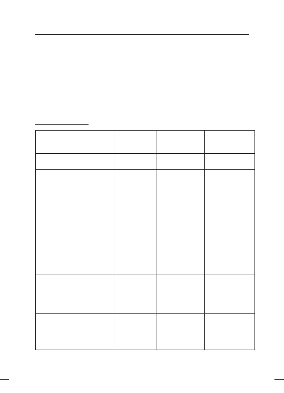
No of Lamps Bulb location Oven Type Instructions
2 Side All Remove the oven shelves. Grasp the
lens cover on the light fitting and pull
it away from the side of the oven. Unscrew the bulb and replace. Replace the
lens cover
1 Rear Fanned/Multifunction Remove the oven shelves. Remove the
loose oven back by unscrewing the 4
securing screws (one at each corner)
and remove. Unscrew the lens cover by
turning anticlockwise. Remove the bulb
and replace. Replace the lens cover and
oven back.
1 Rear Conventional Remove the oven shelves. Unscrew the
lens cover by turning anticlockwise.
Remove the bulb and replace. Replace
the lens cover.
Page 38

CUSTOMER CARE
Product Description Product Code Quantity Where Used
Rectangular carbon filters 082612620 2 Hoods
Round carbon filters 082611571 1 Hoods
Ceramic hob scraper kit 082606781 1 All ceramic glass hobs
including induction
Ceramic hob cleaner and
conditioner
082606780 1 All ceramic glass hobs
including induction
Sealed hotplate conditioner 082606783 1 All sealed / solid plate
hobs
Stainless steel cleaner 082606764 1 All stainless steel parts
Oven cleaner spray 082606786 1 All cookers, inside
cavities and on glass
Multi-purpose kitchen cleaner 082606782 1 General kitchen
cleaner
E-cloth 082813300 1 All cookers, for clean-
ing glass and stainless
steel
COOKSHOP
To order or enquire about any of these
products, please call the Spares Sales
team on 0870 458 9961
Page 39

Page 40

customer care
In case of difficulty within the UK, please call Prima Customer Care Helpline on
0844 248 4201
When you dial this number you will hear a recorded message and be given a number of
options. This indicates that your call has been accepted and is being held in a queue.
Calls are answered in strict rotation as our Customer care Representatives become
available.
Please ensure that you have the product’s model no and serial no available when you
call. These can be found on the silver data label on your product which is located:
Ovens Open the door; adjacent to the oven cavity
High-level grill products Inside the base compartment
Hobs On the underside of the product
Enter appliance numbers here for future reference:
Model No
Serial No
serVIce recorD
For customers outside the UK and Northern Ireland, please contact your local supplier.
Stoney Lane, Prescot, Merseyside, L35 2XW
Date of purchase Installed by Installation Date
Place of purchase:
Date Part(s) replaced Engineer’s name
08 30547 00a 02.2010
 Loading...