

PRESONUS DigiTube Single-Channel Tube, DigiTube User Manual

Copyright © 2001, PreSonus Audio Electronics, Inc.
ALL RIGHTS RESERVED
DigiTUBE
Single-Channel Tube Mic-Preamplier
with S/PDIF Output
USER’S MANUAL 1.1

1 Overview..................................................................................1
1.1 Introduction ............................................................................... 1
1.2 Features .................................................................................... 2
2 Controls & Operation................................................................ 4
2.1 Front Panel................................................................................. 4
2.1.1 Tube Preamp Section ................................................................... 4
2.1.2 Equalizer Section ........................................................................ 6
2.2 Back Panel ................................................................................. 9
2.2.1 Digital Section ............................................................................ 9
2.2.2 Analog Section............................................................................ 9
2.3 Vacuum Tubes .......................................................................... 12
2.3.1 Replacing the Vacuum Tube ........................................................ 10
2.4 Power Supply ........................................................................... 12
3 Technical Specications ......................................................... 12
4 PreSonus Limited Warranties ................................................. 14
TABLE OF CONTENTS
i

1
OVERVIEW 1
1.1 INTRODUCTION
Thank you for purchasing the PreSonus DigiTUBE Single-Channel Tube MicPreamplier with S/PDIF Output. This preamp was designed using state of the
art components to deliver crystal clear audio for an indenate period of time.
We believe the DigiTUBE to be an exceptional sounding unit and an exceptional
value.
Please contact us at 1-800-750-0323 with your questions or comments regarding this product. PreSonus Audio Electronics, Inc. is committed to constant
product improvement and believes the best way to accomplish this task is by
listening to the experts on our gear, our valued customers. We appreciate the
support you have shown us through the purchase of this product.
Please pay close attention to how you connect your DigiTUBE to your system.
Improper grounding is the most common cause of noise problems found in
studio or live sound systems. We urge you to scan this manual before hooking
up your DigiTUBE to familiarize yourself with its features and applications.
Good luck and enjoy your DigiTUBE!

1 OVERVIEW
2
1.2 FEATURES
The following is a summary of your DigiTUBE’s features:
Dual Servo Gain Stage
Your DigiTUBE contains a dual servo gain stage (no capacitors). This design
provides ultra low noise performance and wide dynamic control. The DigiTUBE
can boost the desirable signal without increasing unwanted background noise.
Mic/Instrument/Line Input
The DigiTUBE has a Neutrik™ combo (XLR & ”) connector. The XLR input can
be used for microphone signals and phantom power is available for condenser
mics when the 48V switch is engaged. The XLR will also accept line level signals
when the PAD/LINE switch is engaged. The ” input will accept instrument level
signals, only. The PAD/LINE switch has no effect on the ” input and it should
be understood that the ” input is not designed to accept line level signals.
Pad/Line
A switch on the front panel may be used to engage a -20dB pad for mic level
signals or change the XLR input operating level from mic to line. Using the 20dB pad provides a more manageable signal from high output devices giving
the operator greater control over the incoming signal and a much reduced
chance of over-driving the input, thereby avoiding distortion.
48V
The DigiTUBE has 48V phantom power available. Phantom power assures
optimum performance from your condenser microphone without the need of
an external power supply. A 80Hz switch is provided on the front panel of the
DigiTUBE that enables the user to insert an 80Hz lter. Often referred to as a
rumble lter, this feature is useful for eliminating bothersome low-end sounds
such as air conditioning noise without greatly altering the desired audio.
Parametric Equalizer
The equalizer section is equipped with three dual concentric potentiometers
The outer control selects the frequency and the inner control boosts/cuts the
selected frequency. The EQ controls are LOW, MID, HI from left to right. The
bandwidths are broad enough and have enough overlap to allow a very effective
contour of the incoming audio signal.

3
OVERVIEW 1
Drive
The DigiTUBE is provided with a DRIVE potentiometer for controlling the amount
of signal routed through the 12AX7 vacuum tube. This feature lets you control
how much saturation of the signal occurs. Greater levels of tube saturation give
the signal greater warmth and a richer sound. This feature works equally well
on mics and instruments and is just what is needed to tame that ‘brittle’ sound
encountered with different types of digital media.
Internal Clock
An internal clock is provided for 44.1 kHz or 48 kHz operation selectable by way
of the switch on the back panel. An INTERNAL/EXTRERNAL selector and a BNC
connector for external clock input can be found on the back panel as well as the
S/PDIF connector for the DigiTUBE’s digital output.
4
2 CONTROLS & OPERATION
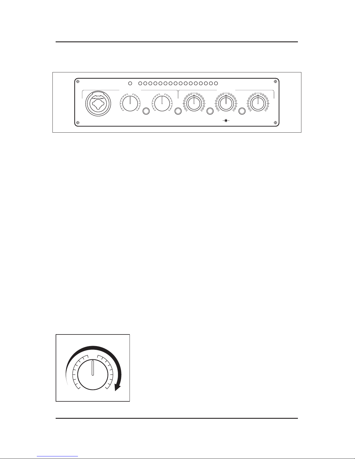
2.1 FRONT PANEL
The front panel of the DigiTUBE contains:
GAIN (dB) LOW MID HIGH
EQ
IN
MIC/INSTRUMENT
LINE
POWER
-42 -36 -30 -24 -18 -12 -6 -3 0 3 6 9 12 15 18 24
OUTPUT LEVEL (dBu)
2k
900 5k
120
30 1k
0
-12 +12
5k
3k 15k
0
-12 +12
DRIVE
TUBE PREAMP EQUALIZER
24
3 48
5
0 10
80Hz48V
PAD/
LINE
-12 +12
0
FREQLEVEL
The front panel of the DigiTUBE is divided into two sections: the tube preamp
controls are located on the left hand side of the unit’s front panel and the
equalizer section is on the right.
2.1.1 TUBE PREAMP SECTION
Neutrik™ Combo Microphone (XLR) / Instrument (”) Input
Drive Control
Pad/Line Switch
Gain Control (3dB - 48dB)
+48V Phantom Power Switch
Mic/Line/Instrument Input
The DigiTUBE has a Neutrik™ combo connector which provides both an XLR and
a ” TS input. The XLR connector can accept microphones or by engaging the
PAD/LINE switch, line level signals. The ” input is for instrument level signals
only. If you wish to adapt a line level device with a ” connector, An XLR
connector with pins 1 and 3 tied together for ground and the hot connected to
pin 2 must be made. This adapts the unbalanced line level cable to input signal
via the XLR input and the PAD/LINE switch to convert the input to accept a line
level signal.
Drive
The DRIVE potentiometer controls how much signal
is routed through the 12AX7 vacuum tube. The effect
achieved by this procedure can be subtle to extreme,
depending on the setting being used. A ‘warming up’
of the sound can be noticed at lower settings. This
effect can be used to compensate for the harshness commonly encountered in digital signals with
5
0 10
M
O
R
E
 Loading...