

Presonus CENTRAL STATION User Manual

CENTRAL STATION
STUDIO CONTROL CENTER
USER’S MANUAL
version 1.1
© 2004 PreSonus Audio Electronics, Incorporated.
All rights reserved.

WARRANTY
PreSonus Limited Warranty
PreSonus Audio Electronics Inc. warrants this product to be free of defects in material and workmanship
for a period of one year from the date of original retail purchase. This warranty is enforceable only by the
original retail purchaser. To be protected by this warranty, the purchaser must complete and return the
enclosed warranty card within 14 days of purchase. During the warranty period PreSonus shall, at its
sole and absolute option, either repair or replace, free of charge, any product that proves to be defective
on inspection by PreSonus or its authorized service representative. To obtain warranty service, the
purchaser must first call or write PreSonus at the address and telephone number printed below to obtain
a Return Authorization Number and instructions of where to return the unit for service. All inquiries must
be accompanied by a description of the problem. All authorized returns must be sent to the PreSonus
repair facility postage prepaid, insured and properly packaged. PreSonus reserves the right to update
any unit returned for repair. PreSonus reserves the right to change or improve the design of the product
at any time without prior notice. This warranty does not cover claims for damage due to abuse, neglect,
alteration or attempted repair by unauthorized personnel, and is limited to failures arising during normal
use that are due to defects in material or workmanship in the product. Any implied warranties, including
implied warranties of merchantability and fitness for a particular purpose, are limited in duration to the
length of this limited warranty. Some states do not allow limitations on how long an implied warranty
lasts, so the above limitation may not apply to you. In no event will PreSonus be liable for incidental,
consequential or other damages resulting from the breach of any express or implied warranty, including,
among other things, damage to property, damage based on inconvenience or on loss of use of the
product, and, to the extent permitted by law, damages for personal injury. Some states do not allow the
exclusion of limitation of incidental or consequential damages, so the above limitation or exclusion may
not apply to you. This warranty gives you specific legal rights, and you may also have other rights, which
vary form state to state. This warranty only applies to products sold and used in the United States of
America. For warranty information in all other countries please refer to your local distributor.
PreSonus Audio Electronics, Inc.
7257 Florida Blvd.
Baton Rouge, LA 70806
(225) 216-7887
(800) 750-0323
www.presonus.com
© 2004, PreSonus Audio Electronics, Incorporated. All rights reserved.

TABLE OF CONTENTS
1 Overview
1.1 Introduction 4
1.2 Features 4
2 Controls & Connections
2.1 Front Panel Layout 6
2.2 Talkback & Phones 6
2.3 Cue / Main Select 7
2.4 Meter 7
2.5 Passive Speaker Control 8
2.6 Back Panel Layout 9
2.7 Connectors 10
2.8 Power Supply 10
3 Operation
3.1 Quick Start Up 11
3.2 Hook Up Diagram 13
3.3 Meter Calibration Procedure 14
3.4 Application Diagrams 15
4 Technical
4.1 Specifications 17
4.2 Block Diagram 19
3

OVERVIEW
1.1 INTRODUCTION
Thank you for purchasing the PreSonus CENTRAL STATION. PreSonus Audio Electronics has designed the
CENTRAL STATION utilizing high-grade components to insure optimum performance for many years. We
believe the CENTRAL STATION to be an exceptional sounding unit and an exceptional value. We encourage
you to contact us at 1-800-750-0323 with any questions or comments you may have regarding your PreSonus
equipment. PreSonus Audio Electronics is committed to constant product improvement, and we value your
suggestions highly. We believe the best way to achieve our goal of constant product improvement is by
listening to the real experts, our valued customers. We appreciate the support you have shown us through the
purchase of this product.
Please pay close attention to how you connect your CENTRAL STATION to your system. Improper grounding
is the most common cause of noise problems found in studio or recording environments. We would like to
suggest that you use this manual to familiarize yourself with the features, applications and correct connection
procedure for your CENTRAL STATION before trying to hook it up to your system. Thank you, once again, for
buying our product and may we wish you Good Luck and enjoy your CENTRAL STATION!
1.2 FEATURES
The CENTRAL STATION is the ultimate studio-monitoring interface for the modern digital studio featuring three
sets of stereo analog inputs to accommodate DAW/Mixer or Tape/CD players. Two stereo analog inputs
feature TRS balanced and the third stereo input features RCA inputs with trim control for matching signals at
different levels. In addition, the CENTRAL STATION will accommodate two digital inputs via S/PDIF or
TOSLINK providing D/A conversion up to 24Bit/192kHz. This allows the user to monitor DAW and CD/DAT
outputs through the same converter for the most accurate A/B comparison. The digital to analog converter
offers the highest possible audio quality with over 115dB dynamic range and ultra high quality analog circuitry.
The CENTRAL STATION features three sets of monitor outputs, each with their own set of passive trim pots.
The monitoring section also provides MUTE, DIM and MONO controls. In addition, the CENTRAL STATION
includes a set of CUE outputs that can feed headphone amplifiers and a separate stereo MAIN line level
output.
PURELY PASSIVE SIGNAL PATH
The CENTRAL STATION features a PURELY PASSIVE SIGNAL PATH for ultimate sonic performance. The
main audio path of the CENTRAL STATION uses no amplifier stages including op amps or active IC's
(integrated circuits) that add noise, color, distortion, and give that "pinched" sound. Distortion produced by op
amps and IC's also gives added ear fatigue.
Signal routing in the CENTRAL STATION is achieved utilizing 34 sealed mechanical relays (instead of active
IC's) maintaining a minimal signal path design wherein extraneous electronics are hard-wire bypassed. Using
4

CONTROLS & CONNECTIONS
relays ensures the most transparent signal path maximizing dynamic range, frequency range, and headroom,
while minimizing noise and coloration. The CENTRAL STATION uses the highest quality passive components
including military grade 1% tolerance metal film resistors, multi-element potentiometers and ultra-durable
connectors to deliver the highest sonic performance.
METERING
The CENTRAL STATION has dual fast-acting 30-segment peak/hold LED's for accurate metering. The front
panel of the CENTRAL STATION includes both dBu and dBfs scale as well as peak/hold clear switch and
meter alignment switch for additional metering options.
TALKBACK
The CENTRAL STATION has an onboard omni directional condenser TALKBACK microphone which is routed
through the CUE outputs for communication between artist and engineer. The CENTRAL STATION also
includes a microphone XLR input on the rear panel for use with an external microphone. When TALKBACK is
used the CUE mix is automatically "dimmed" for added ease of communication.
REMOTE CONTROL (optional)
An additional DB15 connector on the rear of the CENTRAL STATION to allow for a wired remote which
controls VOLUME, TALKBACK, MUTE, input source switching and speaker output switching functions.
SUMMARY OF FEATURES
• Five stereo inputs (2 digital and 3 analog)
• 24-Bit DAC for Digital Inputs (>115dB dynamic range)
• Passive Audio Path - no op amps or IC's in main audio path
• Three sets of monitor outputs; each with passive volume trims
• Talkback microphone with volume to feed CUE outputs
• Accurate dual 30-segment LED for metering
• Two front panel headphone jacks with separate volume control
• MAIN and CUE stereo output have independent input source
• Optional console remote control
5
CONTROLS & CONNECTIONS
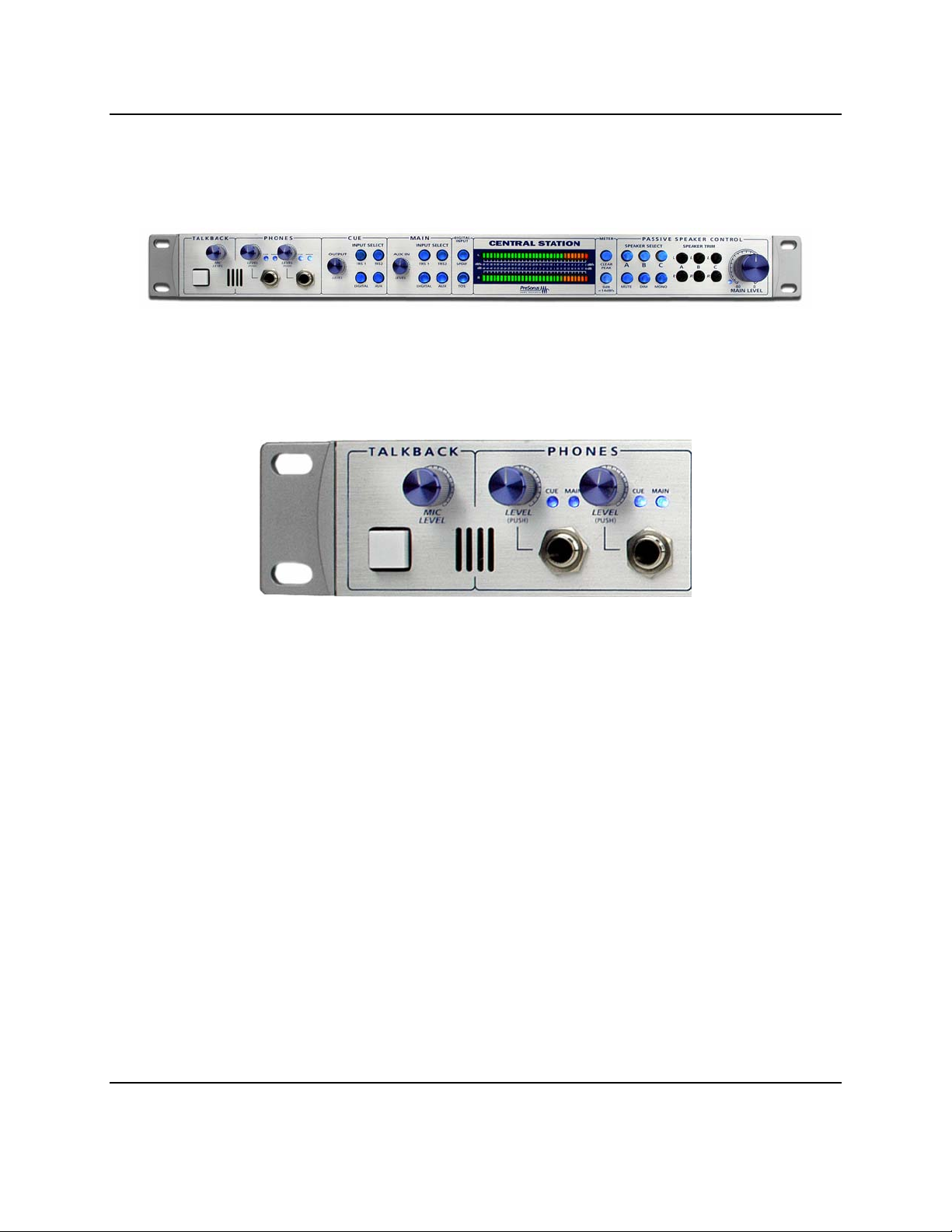
2.1 FRONT PANEL LAYOUT
The front panel of the CENTRAL STATION is divided into four sections – Talkback/Headphones, Cue/Main
Select, Meter, Passive Speaker Control
2.2 TALKBACK / PHONES
• TB -Talkback ‘On’ Button: When pressed, this button activates the Talkback microphone. This is a
momentary type switch – the microphone is ‘ON’ only while the button is pressed. An external foot
pedal connected to the PEDAL input on the rear of the chassis can also be used to activate the
TALKBACK microphone.
• Mic Level: Adjusts the talkback microphone sensitivity.
• Phones Level (2): Dual function. When turned, the knob adjusts the headphone volume level. When
pressed in, switches between MAIN and CUE audio input paths.
6
 Loading...