

Page 1
InstructionSheet
Light Engine
Mounting Screw
Trim
Driver
Mounting Screws
Driver Bracket
Driver Bracket
Mounting Screws
Light Engine
Connector
Safety Cable
C
anopy
Outlet Box
Mounting Screws
Screws #8-32
(2)
Mounting Plate
Light Engine
Mounting Screw
Trim
Driver
Mounting Screws
Driver Bracket
Driver Bracket
Mounting Screws
Light Engine
Connector
Driver
M
ounting Screws
Connector
Driver Bracket
Mounting Screws
Driver Bracket
Light Engine
Mounting Screw
Light Engine
Trim
Safety Cable
Safety Cable
InstructionSheet
Part No. . . . . . . . . . . . . . . . . . . . . . . . . . . . . . . . .93011925
IMPORTANT SAFETY INFORMATION. READ AND FOLLOW ALL SAFETY INSTRUCTIONS. Follow label information
and instructions concerning Wet or Damp Locations, installation near combustible materials, insulation, building materials,
and proper lamping. Do not install in areas subject to combustible vapors or gases. Before wiring to power supply and
during servicing or relamping, turn off power at fuse or circuit breaker. All servicing or relamping must be performed by
qualified service personnel. Product must be grounded to avoid potential electric shock or other potential hazard.
Product must be mounted in locations and at heights and in a manner consistent with its intended use, and in
compliance with the National Electrical Code and local codes. The use of accessory equipment not recommended by
the manufacturer or installed contrary to instructions may cause an unsafe condition. Do not block light emanating from
product in whole or part, as this may cause an unsafe condition. Do not allow items such as drapes, curtains, screens or
the like to come into contact with the product or to block light from the product, as this may cause an unsafe condition.
INSTALLATION INSTRUCTIONS
LD6_S SERIES
CEILING MOUNT
.
etach mounting plate from cylinder canopy by loosening the two #8-32
1
D
crews that hold the strap in the canopy (Fig.1).
s
2. Make electrical connections. Connect ground wires to green ground leads.
onnect power supply (line) to black leads
C
WARNING: DO NOT pinch wires. Consult a qualified electrician for all
other options that require other wiring configurations.
.
ecure mounting plate to outlet box with screws from outlet box (Fig.1).
3
S
4. Secure the fixture in place by tightening the screws from step 1.
NSTALLATION
I
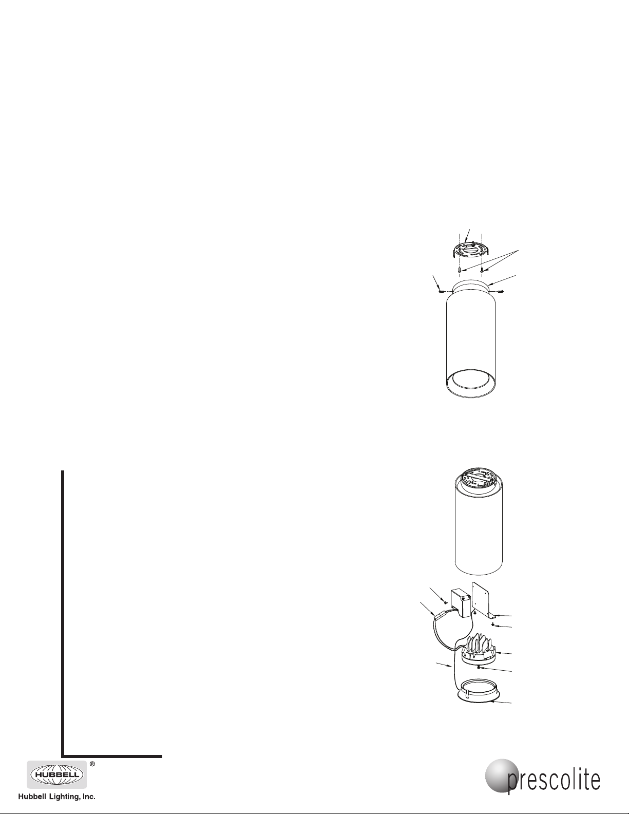
nsert supplied #8-32 x 1/2” screws into supplied S-4 strap through tapped
.
I
1
oles located 2-3/4” apart in orienation shown in Fig 1. (Holes in fixture
h
canopy must line up with these screws.)
ount strap to outlet box with screws (by others) with screw stems facing
2.M
outward. Rotate strap to adjust fixture to correct position.
3. Connect supply wires: Black to Line, White to Common, Green to Ground.
(DM only: Connect Gray (+) and Violet (-) to appropriate 0-10V dimming
control per National Electrical Code and local codes.
4. Secure fixture canopy with two mounting nuts supplied.
5. Fixtures used in wet locations, place the two supplied o-rings under the
heads of the mounting screws and secure mounting nuts. Area around fixture canopy and mounting surface must be sealed.
LIGHT ENGINE REPLACEMENT
1.
Remove lensed reflector assembly by pulling from the edges. Reflector
assembly is held by a safety cable.
2. Loosen captive screw holding the light engine. Carefully lower and discon-
nect light engine connector from driver connector. See Fig. 2.
3. Connect replacement light engine connector to driver connector and line up
light engine heat sink fins with mounting bracket until seated into place and
tighten captive screw.
4. Reinstall reflector assembly.
FIG. 1
www.prescolite.com • Prescolite TollFree Technical Support 1.888.PRS.4TEC • Hours: 8am - 5pm ET
LED DRIVER REPLACEMENT
1.
Remove lensed reflector assembly by pulling from the edges. Reflector
assembly is held by a safety cable.
2. Loosen captive screw holding the light engine. Carefully lower and discon-
nect light engine connector from driver connector. See Fig. 2. Set aside.
3. Remove driver bracket mounting screw attaching safety cable and remove
reflector assembly. Set aside.
4. Remove remaining driver bracket mounting screws and lower driver brack-
et. Disconnect all driver wiring and replace driver by removing driver
mounting screws. See Fig 2.
5. Mount replacement driver and reconnect wiring according to installation
step 3.
6. Reinstall driver bracket and safety cable holding reflector assembly using
mounting screws. Reconnect light engine connector to driver connector
and line up light engine heat sink fins with mounting bracket until seated
into place and install with captive screw.
7. Reinstall reflector assembly.
NOTE: Do not pinch LED wires between the sliding parts.
KEEP THESE INSTRUCTIONS
701 Millennium Boulevard • Greenville, SC 29607
ith representatives of
W
Copyright 2009, 10/30/09 revision, All Rights Reserved - Printed in U.S.A.
fices in principal cities throughout North
FIG. 2
America.
 Loading...