

Page 1
UMB-DBT / UMB-DBTS
Installation Guide
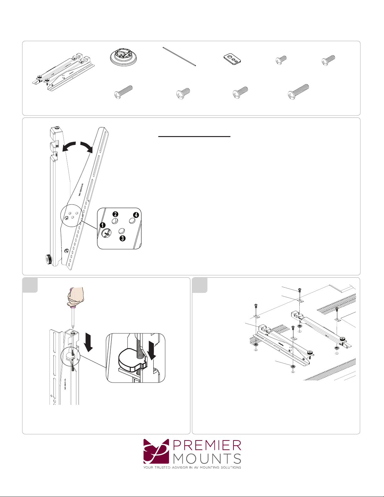
Display Bracket
(1 Pair)
Universal Spacer
(Qty 8)
M6 x 25 mm screw
(Qty 4)
Thread Depth Indicator
(Qty 1)
M8 x 12 mm screw
(Qty 4)
Universal Washer
(Qty 4)
M8 x 16 mm screw
(Qty 4)
M6 x 12 mm screw
(Qty 4)
M6 x 25 mm screw
(Qty 4)
M6 x 16 mm screw
Tilt Adjustments
Tilt adjustments can be made shown in f igure 1 by removing the Phillips
screw on the display brackets and installing it to anot her hole.
( 0º - 5º - 10º - 20º) Degrees
(Qty 4)
1
Figure 1
If necess ar y use a Phillips screw driver
to adjust the clamp brackets down.
2
(4) Di splay B rackets
Use a thread depth indicator to find the appropriate hardware.
Install the display brac kets using four (4) M 6 or M 8 screws and
four (4) univer sal washers. Use universal spacers if neces sary.
(4) M6 or M8 Screws
(4) Universal Washer
(4) Universal Spacer
www.mo unts.com | North A meric a 80 0.368.9700 | I nterna tiona l +1-714 -632-7100
Page 2

UMB-DBT / UMB-DBTS
Installation Guide
3
5
Commercially available rec ommended unistrut
P4100T 1 5/ 8” x 13/16” 14 gauge.
Unistr ut
Display Br ackets
Unistr ut
Attach the display bracket s to the unistrut.
4
Leveling
Leveling adjustm ent s can be made shown in f igure 2 by turning the knurl knob.
Use a Phillips screw driver to s ecure
the display brackets to the unistr ut.
Figure 2
www.mo unts.com | North A meric a 80 0.368.9700 | I nterna tiona l +1-714 -632-7100
950013 5_ 0
 Loading...