

Page 1
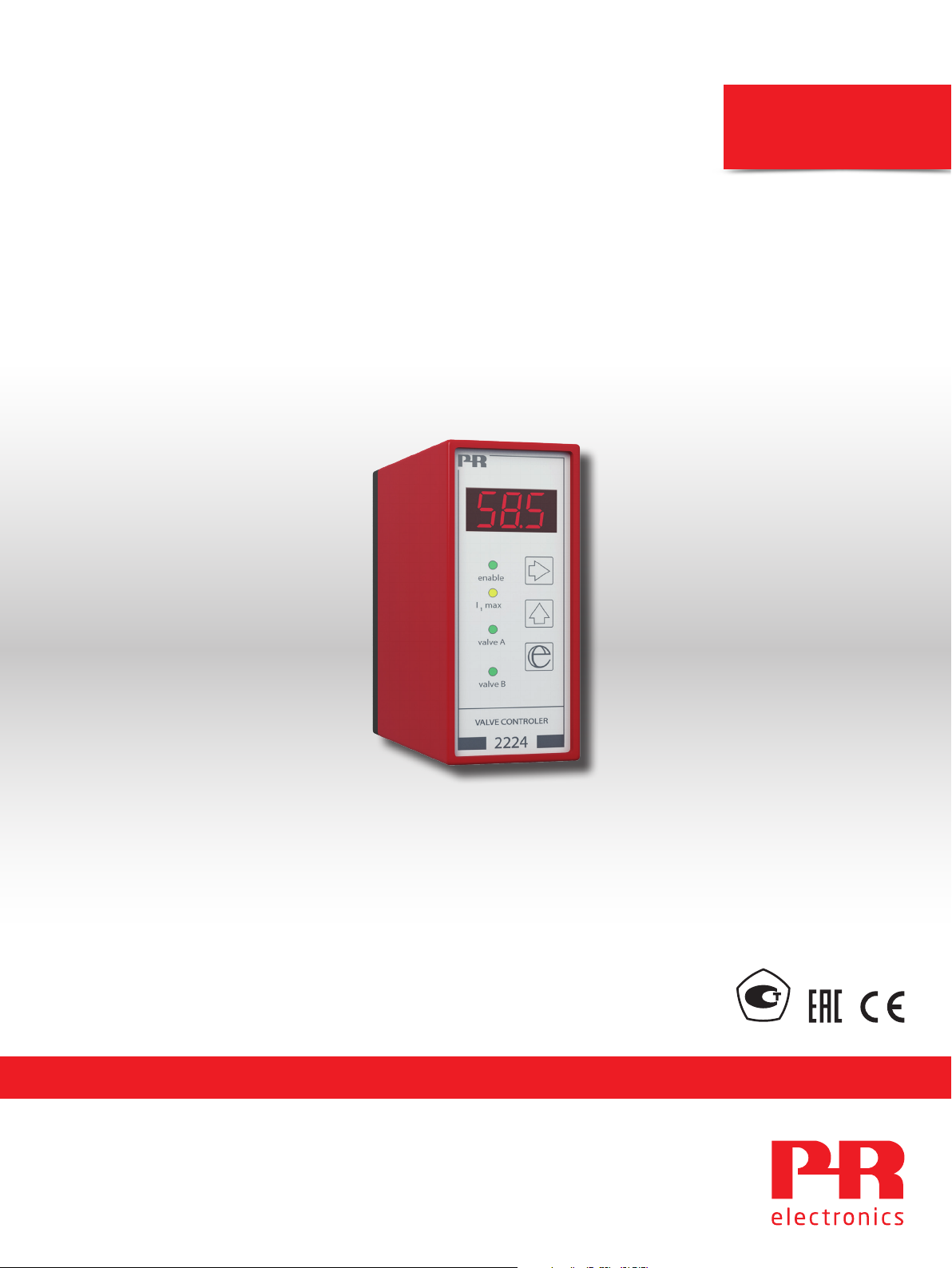
Product Manual
2224
Valve controller
PERFORMANCE
MADE
SMARTER
TEMPERATURE | I.S. INTERFACES | COMMUNICATION INTERFACES | MULTIFUNCTIONAL | ISOLATION | DISPLAY
No. 2224V103-UK
From serial no.: 060223001
Page 2

6 Product Pillars
to meet your every need
Individually outstanding, unrivalled in combination
With our innovative, patented technologies, we make signal conditioning smarter and simpler. Our portfolio is composed of six
product areas, where we offer a wide range of analog and digital devices covering over a thousand applications in industrial
and factory automation. All our products comply with or surpass the highest industry standards, ensuring reliability in even
the harshest of environments and have a 5-year warranty for greater peace of mind.
Our range of temperature transmitters and sensors provides the highest level of signal integrity from the
measurement point to your control system. You can convert industrial process temperature signals to analog, bus or
digital communications using a highly reliable point-to-point solution with a fast response time, automatic selfcalibration, sensor error detection, low drift, and top EMC performance in any environment.
We deliver the safest signals by validating our products against the toughest safety standards. Through our
commitment to innovation, we have made pioneering achievements in developing I.S. interfaces with SIL 2 Full
Assessment that are both efficient and cost-effective. Our comprehensive range of analog and digital intrinsically
safe isolation barriers offers multifunctional inputs and outputs, making PR an easy-to-implement site standard.
Our backplanes further simplify large installations and provide seamless integration to standard DCS systems.
We provide inexpensive, easy-to-use, future-ready communication interfaces that can access your PR installed base
of products. All the interfaces are detachable, have a built-in display for readout of process values and diagnostics,
and can be configured via push-buttons. Product specific functionality includes communication via Modbus and
Bluetooth and remote access using our PR Process Supervisor (PPS) application, available for iOS and Android.
Our unique range of single devices covering multiple applications is easily deployable as your site standard. Having
one variant that applies to a broad range of applications can reduce your installation time and training, and greatly
simplify spare parts management at your facilities. Our devices are designed for long-term signal accuracy, low
power consumption, immunity to electrical noise and simple programming.
Our compact, fast, high-quality 6 mm isolators are based on microprocessor technology to provide exceptional
performance and EMC-immunity for dedicated applications at a very low total cost of ownership. They can be
stacked both vertically and horizontally with no air gap separation between units required.
Our display range is characterized by its flexibility and stability. The devices meet nearly every demand for display
readout of process signals, and have universal input and power supply capabilities. They provide a real-time
measurement of your process value no matter the industry, and are engineered to provide a user-friendly and
reliable relay of information, even in demanding environments.
Page 3

Valve controller
2224
Contents
How to dismantle system 2200 .......................................................................... 2
Applications ............................................................................................ 3
Technical characteristics ................................................................................. 3
Mounting ............................................................................................... 3
Order ................................................................................................... 4
Electrical specifications.................................................................................. 4
Block diagram........................................................................................... 5
Timing diagram ......................................................................................... 6
DIP-switch programming................................................................................. 6
Wiring diagrams for joystick / potentiometer input ......................................................... 8
Wiring diagrams for DC current input...................................................................... 9
Wiring diagrams for DC voltage input ..................................................................... 10
Technical description .................................................................................... 11
Routing diagram ........................................................................................ 12
Configuration / operating the function keys ............................................................... 13
2224V103-UK 1
Page 4
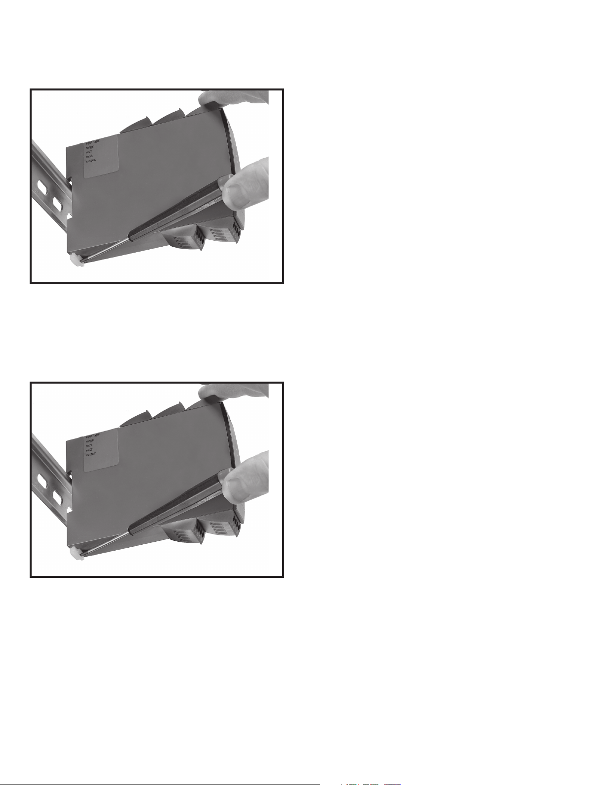
How to dismantle system 2200
Picture 1:
The back panel of the device is detached from the housing by way of a screwdriver.
Picture 2:
After this, the back panel can be pulled out together with the PCB, but please notice the position of the PCB as there is a
number of different positions in the house. Do not pull the wires unnecessarily, instead pull the PCB. Switches and jumpers
can now be moved.
When assembling the back plate and housing, please make sure no wires are stuck.
2 2224V103-UK
Page 5

Valve controller
2224
• Front-programmable
• mA, V, and Ω-programmable input
• Ramp times, jump values, reversal, chopper frequency, and deadband
• 3-digit LED display shows Ivalve % value
• 1 or 2 channels
• Modulated current output for proportional valve
Applications
• Control and regulation of single or double-coil hydraulic and pneumatic proportional valves.
• The unit is used for accurate oil flow regulation, linear soft acceleration and deceleration, modulated output signal, and
programmable deadband.
• Is highly suitable for joystick regulation of A/B movements.
Technical characteristics
• The 2224 Valve Controller is a microprocessor-based unit containing ramp functions for soft start and stop and jump
functions thus avoiding deadband at start and changes between A & B valves.
• The user interface of the valve controller consists of three pushbuttons and a 3-digit LED display. By using these, output
currents, ramp times, jump values, chopper frequency, reversal, deadband, and on/off functions are changed.
• During operation the display shows the present output signal as a % of the Ivalve.
• All parameters are protected against unauthorised changes with a password.
• Changes between A and B valves can be made in two ways. By way of function 1, the A valve is chosen when +Vsupply is
applied to terminal 2. By way of function 2, changes between A/B valves take place automatically according to the value
of the input signal (no signal on terminal 2).
• The output current is enabled / disabled by a digital controlling signal. Please note that the output current is disconnected
until +Vsupply is applied to terminal 3.
• Programmable current or voltage input for standard signals acc. to order schedule, joystick / potentiometer or a special
non-programmable input.
• Digital inputs for external control functions.
• A pulsating current output prevents the connected valve from sticking.
• Optional programming of the modulation frequency (PWM) between 8 and 400 Hz.
• The internal measuring and control circuit ensures that the mean current never exceeds the entered Ivalve.
• If the peak current exceeds 7 A the output will be disabled.
Mounting
• Mounting for a standard 11-pole socket which can be adapted for DIN rail or plate use with PR’s 7023 adaptor and 7024
mounting keying
2224V103-UK 3
Page 6

Order
Type Input Supply Option
2224 0...20 mA
4...20 mA
0...1 V
0.2...1 V
0...10 V
2...10 V
±10 V potentiometer
0...10 V potentiometer
: A
: B
: C
: D
: E
: F
: G
: H
12 V
24 V
: 1
Single valve (A)
: 2
Double valve (A/B)
: A
: B
Electrical specifications
Environmental conditions
Operating temperature . . . . . . . . . . . . . . . . . . . . . . . . . . . . . . . . -20°C to +60°C
Humidity. . . . . . . . . . . . . . . . . . . . . . . . . . . . . . . . . . . . . . . . . < 95% RH (non-cond.)
Protection degree . . . . . . . . . . . . . . . . . . . . . . . . . . . . . . . . . . . IP50
Mechanical specifications
Dimensions (HxWxD) . . . . . . . . . . . . . . . . . . . . . . . . . . . . . . . . . 80.5 x 35.5 x 84.5 mm (D is without pins)
Weight approx. . . . . . . . . . . . . . . . . . . . . . . . . . . . . . . . . . . . . . 130 g
Common specifications
Supply voltage (nom. 12 V / 24 V) . . . . . . . . . . . . . . . . . . . . . . . . . 9.6...28.8 VDC
Internal power dissipation . . . . . . . . . . . . . . . . . . . . . . . . . . . . . . 2 W / 24 V
1,8 W / 12 V
Programming . . . . . . . . . . . . . . . . . . . . . . . . . . . . . . . . . . . . . . Front-programmable
Updating time . . . . . . . . . . . . . . . . . . . . . . . . . . . . . . . . . . . . . 30 ms
Temperature coecient. . . . . . . . . . . . . . . . . . . . . . . . . . . . . . . . 0.01%/°C
Accuracy. . . . . . . . . . . . . . . . . . . . . . . . . . . . . . . . . . . . . . . . . Better than 0.2% of selected range
Linearity error . . . . . . . . . . . . . . . . . . . . . . . . . . . . . . . . . . . . . 0.2%
EMC immunity influence . . . . . . . . . . . . . . . . . . . . . . . . . . . . . . . < 2% of span
Input specifications
Current input
Measurement range . . . . . . . . . . . . . . . . . . . . . . . . . . . . . . . . . . 0...20 and 4...20 mA
Input resistance . . . . . . . . . . . . . . . . . . . . . . . . . . . . . . . . . . . . 50 Ω + PTC (54 Ω)
Voltage input
Measurement range . . . . . . . . . . . . . . . . . . . . . . . . . . . . . . . . . . 0...1, 0.2...1, 0...10 and 2...10 V
Input resistance . . . . . . . . . . . . . . . . . . . . . . . . . . . . . . . . . . . . 10 MΩ
Potentiometer input
Potentiometer min....max.. . . . . . . . . . . . . . . . . . . . . . . . . . . . . . . 0...10 V or ±10 V / 10 kΩ
External potentiometer . . . . . . . . . . . . . . . . . . . . . . . . . . . . . . . . 1 kΩ ≤ potentiometer ≤ 10 kΩ
Operation / shutdown . . . . . . . . . . . . . . . . . . . . . . . . . . . . . . . . . PNP / 2.2 kΩ, 12 / 24 V
Imax.1 & Imax.2 . . . . . . . . . . . . . . . . . . . . . . . . . . . . . . . . . . . . PNP / 2.2 kΩ, 12 / 24 V
A / B channel . . . . . . . . . . . . . . . . . . . . . . . . . . . . . . . . . . . . . . PNP / 2.2 kΩ, 12 / 24 V
Deadband . . . . . . . . . . . . . . . . . . . . . . . . . . . . . . . . . . . . . . . . 0...99.9% of input span
Output specifications
Output voltage . . . . . . . . . . . . . . . . . . . . . . . . . . . . . . . . . . . . . Supply voltage-0.5 V (max.)
Output power. . . . . . . . . . . . . . . . . . . . . . . . . . . . . . . . . . . . . . 36 W (max.)
Output current . . . . . . . . . . . . . . . . . . . . . . . . . . . . . . . . . . . . . 3000 mA mean
Current peak . . . . . . . . . . . . . . . . . . . . . . . . . . . . . . . . . . . . . . 7 A
Reference voltage . . . . . . . . . . . . . . . . . . . . . . . . . . . . . . . . . . . 10 VDC (A valve)
±10 VDC (A & B valve)
Ramp up & down . . . . . . . . . . . . . . . . . . . . . . . . . . . . . . . . . . . . Time 0...10.0 s
PWM frequency. . . . . . . . . . . . . . . . . . . . . . . . . . . . . . . . . . . . . 8...400 Hz in steps of 1 Hz
Of span = Of the presently selected range
4 2224V103-UK
Page 7
Observed authority requirements
EMC. . . . . . . . . . . . . . . . . . . . . . . . . . . . . . . . . . . . . . . . . . . . 2014/30/EU
EAC . . . . . . . . . . . . . . . . . . . . . . . . . . . . . . . . . . . . . . . . . . . . TR-CU 020/2011
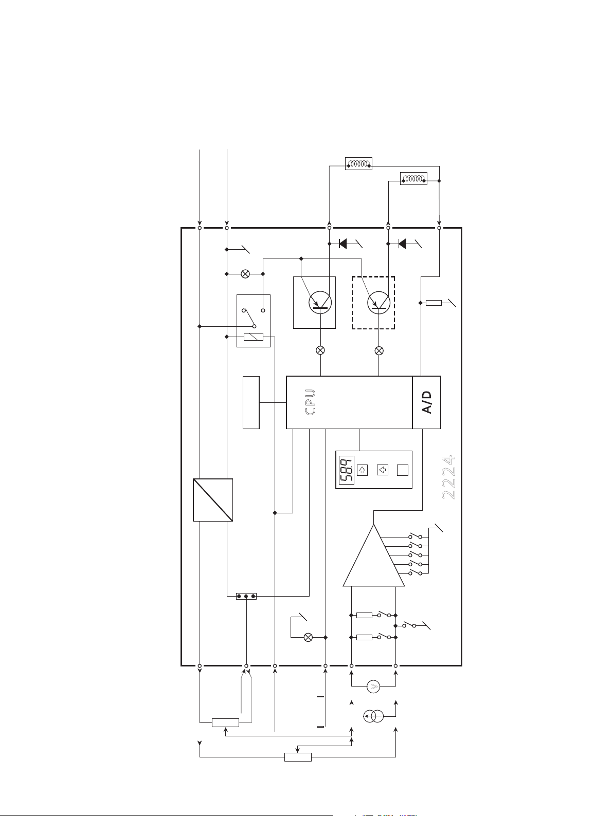
Block diagram
supply gnd
supply +
8
4
A valve +
10
B valve +
11
Valve
return
9
DC
+10 V
DC
- 10 V
2
1
JP 1
driver A
E EP R O M
CPU
driver B
e
2224
8
7
3
2
1
3
DP 1
5
50 10 K
6
4
3
1
2
A or B
aux +10V
2224V103-UK 5
aux -10V
enable/disable
5
7
input +
6
-
+
V
input -
-
+
I Imax / max1 2
Page 8
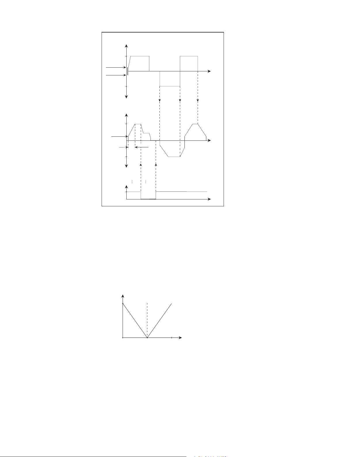
Timing diagram
Input, function 2
0%
jump
value
0%
B
A
B
Imax
1
Imax
ramp
100%
deadband
Output, mean current
100%
100%
B
Digital input, Imax1 / Imax2
+V sup.
0 V
t
Imax
1
2
t
Imax
1
t
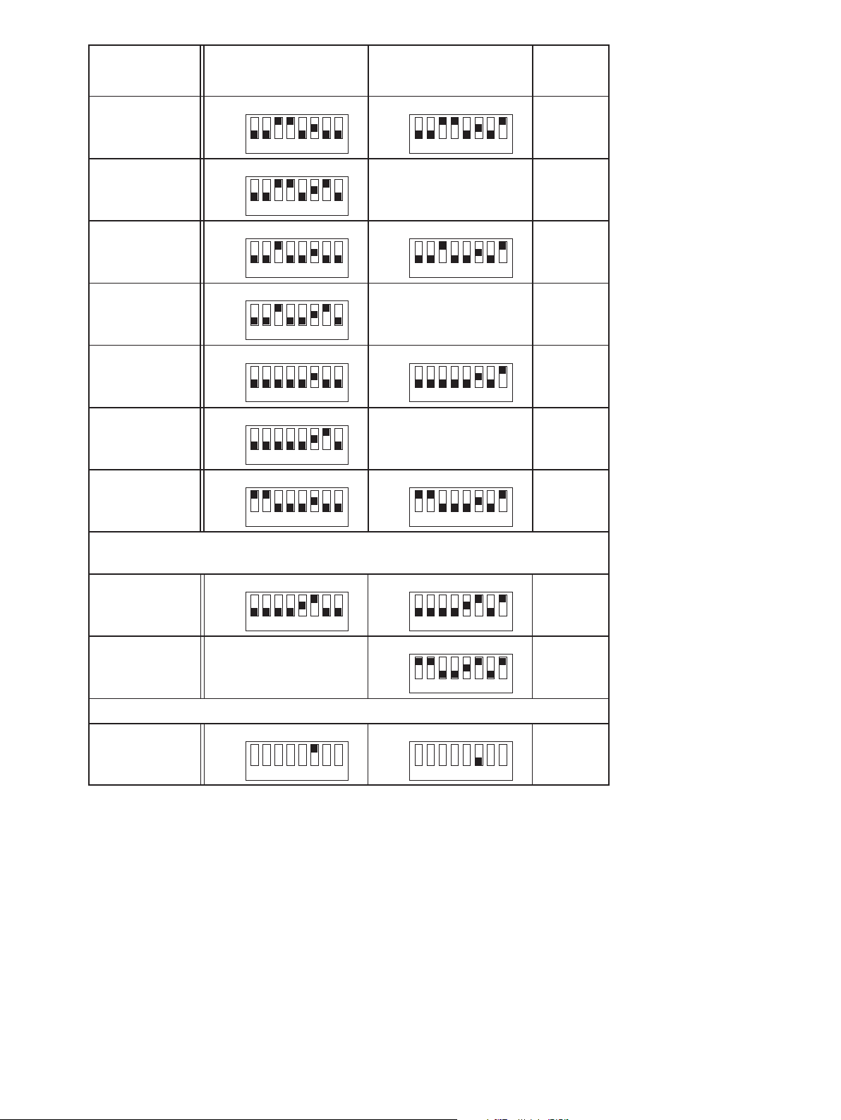
DIP-switch programming
Input signal and function are chosen via the DIP-switch setting.
Function 1:
Single and double valve control. By double valve control, A valve is chosen by applying +Vsupply to terminal 2.
Function 2:
Double valve control with automatic change between A and B valves (no signal on terminal 2).
Output
Input: 0...50% = A valve 100...0%.
Input: 50...100% = B valve 0...100%.
100%
0%
A
Valve
B
Valve
Input
100%50%
6 2224V103-UK
Page 9
Signal
input:
Function
1:
Function
2:
JP1
pos.:
0...20 mA
4...20 mA
0...1 V
0.2...1 V
0...10 V
2...10 V
-10...+10 V
D P 1 D P 1
O n
O f f
1 2 3 4 5 6 7 8 1 2 3 4 5 6 7 8
D P 1
O n
O f f
1 2 3 4 5 6 7 8
D P 1 D P 1
O n
O f f
1 2 3 4 5 6 7 8 1 2 3 4 5 6 7 8
D P 1
O n
O f f
1 2 3 4 5 6 7 8
D P 1 D P 1
O n
O f f
1 2 3 4 5 6 7 8 1 2 3 4 5 6 7 8
D P 1
O n
O f f
1 2 3 4 5 6 7 8
D P 1 D P 1
O n
O f f
1 2 3 4 5 6 7 8 1 2 3 4 5 6 7 8
* *
O n
O f f
*
No function
* *
O n
O f f
*
No function
* *
O n
O f f
*
No function
*
O n
O f f
2 - 3
2 - 3
2 - 3
2 - 3
2 - 3
2 - 3
*
2 - 3
Joystick / potentiometer via
internal reference voltage
0 . . . 1 0 V
- 1 0 . . . + 1 0 V
D P 1 D P 1
O n
O f f
1 2 3 4 5 6 7 8 1 2 3 4 5 6 7 8
No function
( )
*
O n
O f f
D P 1
O n
O f f
1 2 3 4 5 6 7 8
( )
*
( )
*
Input: Grounded Differential
D P 1 D P 1
*
O n
O f f
1 2 3 4 5 6 7 8 1 2 3 4 5 6 7 8
O n
O f f
2 - 3
1 - 2
- - - -
2224V103-UK 7
Page 10
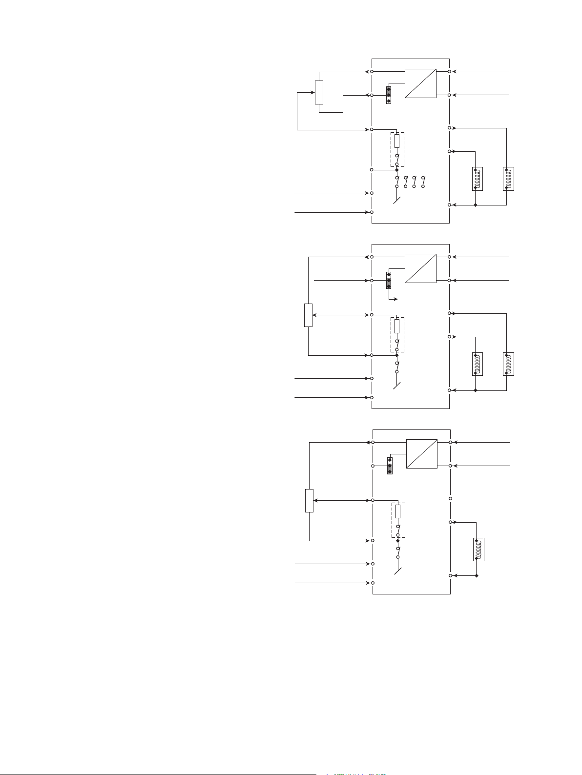
Wiring diagrams for joystick / potentiometer input
Double valve control (A/B valves) from +/-10 VDC
reference supply.
DIP-switch programming:
Function 2.
Double valve control (A/B valves) from +10 VDC
reference supply.
DIP-switch programming:
Function 1 or
Function 2.
Single valve control from +10 VDC reference supply.
DIP-switch programming:
Function 1.
+10 V
- 10 V
Input +
+V supply = I max 1
+V supply = enable
+10 V
+V sup. = A
Input +
Input -
+V supply = I max 1
+V supply = enable
+10 V
1
2
5
6
7
3
1
2
5
6
7
3
1
2
DC
1
2
3
10 K
5
6 8
DP 1
DC
1
2
3
A or B valve
10 K
5
6
DP 1
DC
1
2
3
supply +
8
supply gnd
4
DC
11
B valve +
10
A valve +
21
A
B
9
supply +
8
supply gnd
4
DC
11
B valve +
10
A valve +
A
B
9
supply +
8
supply gnd
4
DC
8 2224V103-UK
Input +
Input -
+V supply = I max 1
+V supply = enable
5
10 K
5
6
6
7
DP 1
3
11
10
9
A valve +
A
Page 11
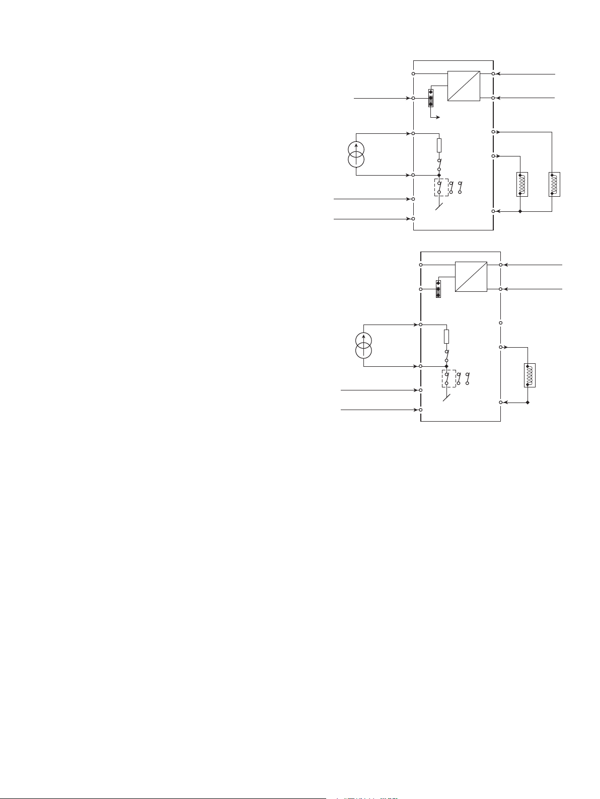
Wiring diagrams for DC current input
Double valve control (A/B valves) from a 4...20 mA
input signal.
DIP-switch programming:
Function 1 or
Function 2.
Single valve control from a 4...20 mA input signal.
DIP-switch programming:
Function 1.
+V sup. = A
Input +
Input -
+V supply = I max 1
+V supply = enable
Input +
Input -
+V supply = I max 1
+V supply = enable
1
2
5
6
7
3
1
2
5
6
7
3
DC
1
2
3
A or B valve
50 ohm
4
6
3 7
DP 1
1
2
3
50 ohm
4
6
DP 1
DC
3 7
DC
DC
8
4
11
10
9
11
10
supply +
supply gnd
B valve +
A valve +
supply +
8
supply gnd
4
A valve +
9
A
B
A
2224V103-UK 9
Page 12
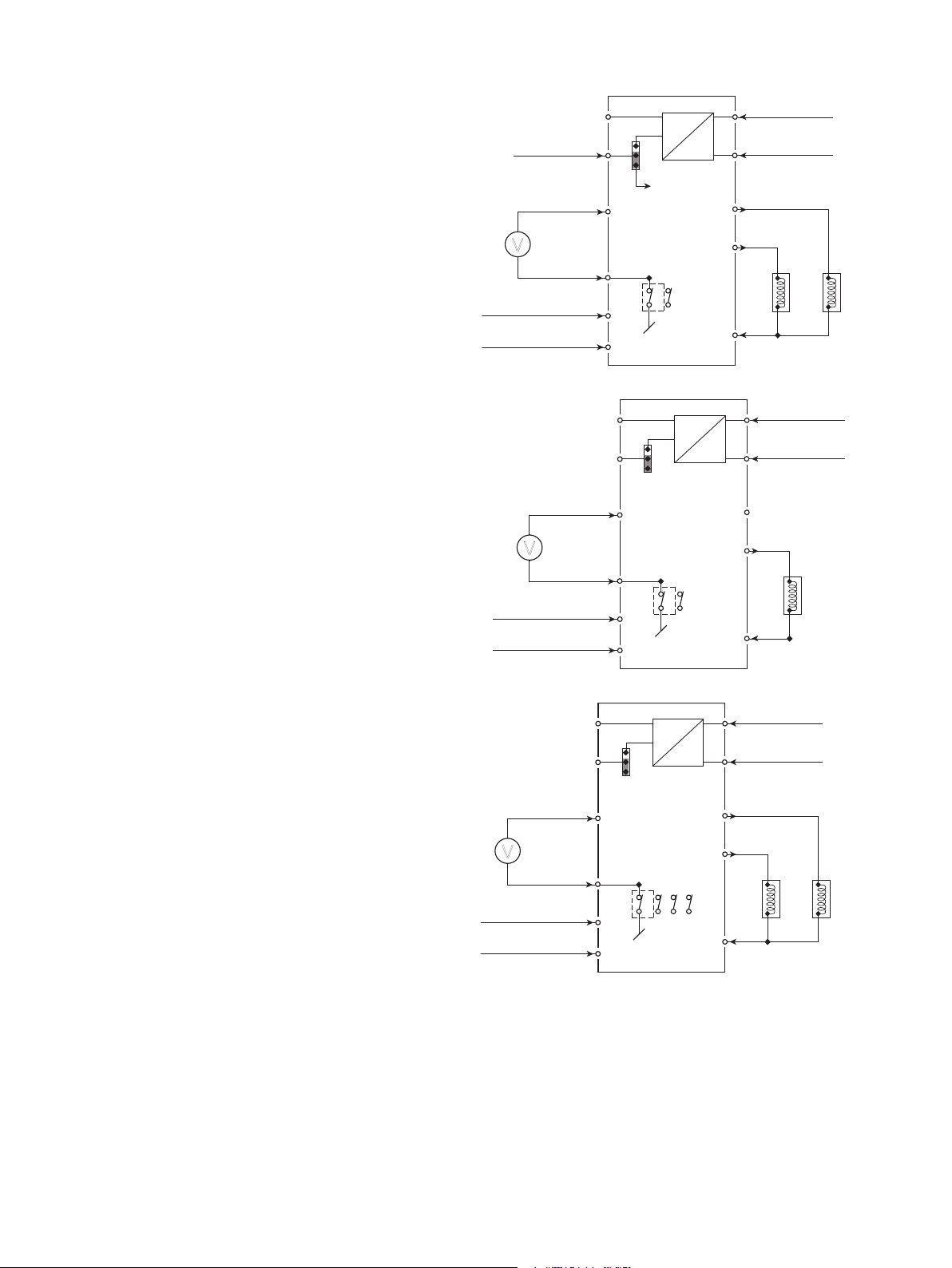
Wiring diagrams for DC voltage input
B
+V supply = enable
Double valve control (A/B valves) from a 0...1 VDC
input signal.
DIP-switch programming:
Function 1 or
Function 2.
Single valve control from a 0...1 VDC input signal.
DIP-switch programming:
Function 1.
Double valve control (A/B valves) from a -10...+10
VDC input signal.
DIP-switch programming:
Function 1 or
Function 2.
+V sup. = A
Input +
V
Input -
+V supply = I max 1
+V supply = enable
Input +
V
Input -
+V supply = I max 1
+V supply = enable
Input +
supply +
DC
8
4
11
10
supply gnd
B valve +
A valve +
1
2
5
DC
1
2
3
A or B valve
6
6
DP 1
1
2
3
3
9
DC
8
4
DC
11
7
3
1
2
5
10
A
supply +
supply gnd
A valve +
B
6
6
DC
3
DP 1
DC
8
4
11
9
supply +
supply gnd
B valve +
7
3
1
1
2
2
3
5
A
10 2224V103-UK
10
V
Input -
6
6
7
1 2 8
DP 1
3
A valve +
A
9
Page 13

Technical description
• To prevent programming during operation, two safety measures have been included: The correct password (030) must be
entered in menu [PAS], and the output must give no signal (000 must be displayed). This is achieved by disconnecting
+Vsupply on terminal 3.
• The 2224 Valve Controller can be controlled by a joystick / potentiometer using the internal +10 V and -10 V supply, or a
process current / voltage signal. For process signals the differential amplifier (DP1 switch 6 off) will reduce disturbances
from noisy signals. Joysticks / potentiometers are connected single-ended (grounded), and it is possible to connect a 10 kΩ
load resistor (DP1 switch 5 on), providing a minimum potentiometer load current.
• A switch between A and B valves can be made in two ways. By way of function 1, the A valve is chosen when +Vsupply is
applied to terminal 2. By way of function 2, changes between A/B valves are made automatically according to the value of
the input signal (no signal on terminal 2). Input: 0...50% = A valve 100...0%. Input: 50...100% = B valve 0...100%.
• When connecting the output to a solenoid please ensure that the peak valve current = Vsupply / Rsolenoid does not
exceed 7A.
• A deadband can be programmed to avoid unintentional activation of the valve in connection with e.g. an inaccurate neutral
position of joysticks. The deadband introduces a threshold which must be exceeded before any output activity will take
place.
• The spring response (bias) can be adjusted to account for the valve seat travel before oil flow.
• Two current limits can be programmed (Imax1 & Imax2) for limit stop detection featuring slow motion before stop. The
active current limit (Imax1 & Imax2) is selected by the PNP input signal on terminal 7.
• The 2224 Valve Controller complies with EMC data only when shielded cabling is used and the shield is connected to
supply ground.
2224V103-UK 11
Page 14
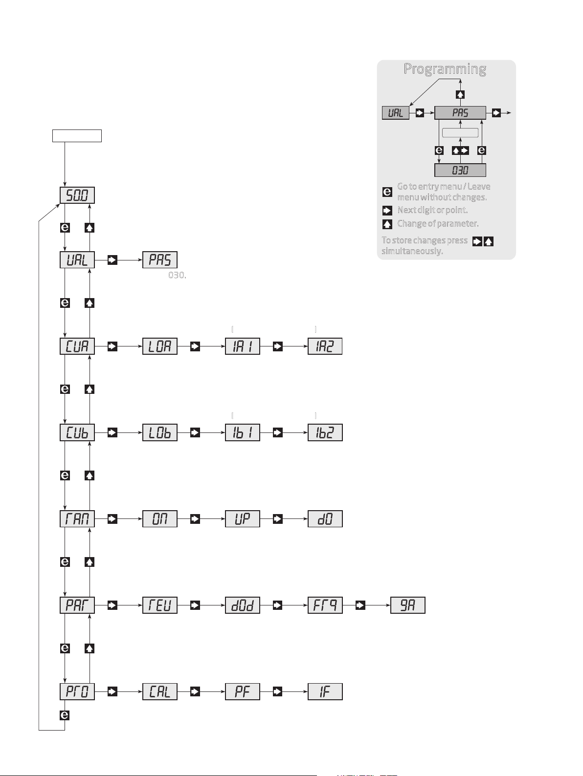
Routing diagram
Programming
1.0 1.1
Power ON
Main menu 0.0.
0.0
Valve control
1.0
Currents for A
2.0
Currents for B
3.0
At power ON, or if no keys have been activated for a
period of 2 minutes, the display returns to main menu 0.0.
Programming
access
1.1
Enter 030.
Applies until power o.
Spring
response
Spring
response
Current limit
I
max1
Current limit
I
max1
Current limit
I
max2
2.32.22.1
0...99.9%0...99.9%0...99.9%
Current limit
I
max2
3.33.23.1
Memory
Go to entry menu / Leave
menu without changes.
Next digit or point.
Change of parameter.
To store changes press
simultaneously.
0...99.9%0...99.9%
Ramp time
down
4.34.24.1
0...10.0 s0...10.0 s
4.0
Ramp
0...99.9%
ON / OFF
ramp
0 = OFF
Ramp time
up
1 = ON
Direct /
Output
5.0 5.4
Inverted
Deadband
0 = Direct
Modulation
frequency
5.35.25.1
8.0...400 Hz 0...3.00 A0...99.9%
1 = Inverted
Integration
factor
0...99.9 times
Controller
6.0 6.36.26.1
No function
Proportional
factor (Gain)
0...99.9 times
Max. output
current
12 2224V103-UK
Page 15
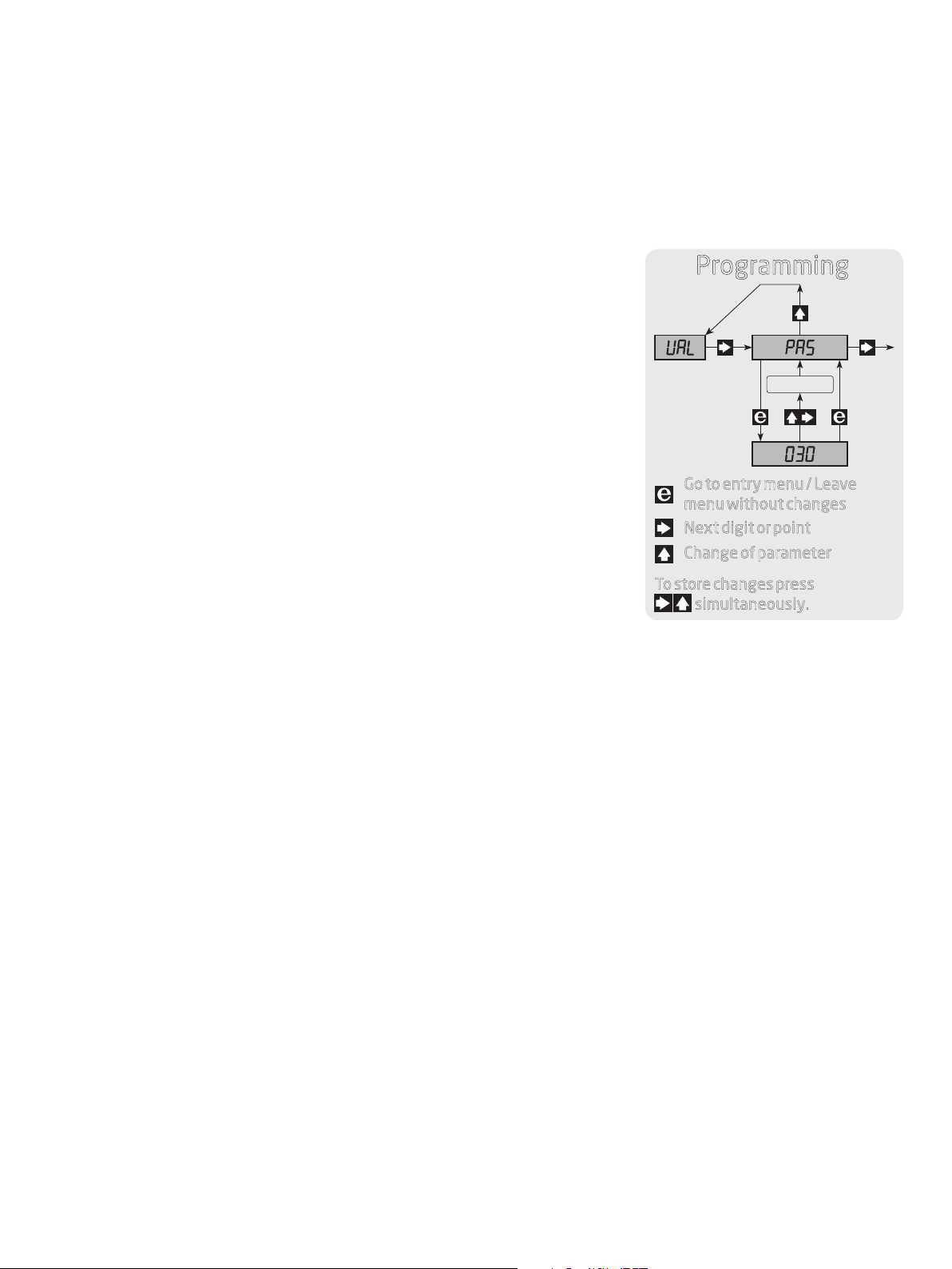
Configuration / operating the function keys
Documentation for routing diagram
General
The configuration is menu-controlled. The main menus are numbered in level 0 (x.0), and the submenus are numbered in level
1 (x.1 to x.4). Each submenu has an accompanying entry menu. The menus are structured in such a way that the menus most
frequently used are closer to the default menu 0.0. Please note that programming is only possible when submenu 1.1 PAS has
the value 030.
All changes are not permanently saved in the EEP rom, until you return to menu 0.0.
Menus and submenus are selected by the 3 function keys 3 , 1, and 2 as outlined
in the routing diagram.
Programming
Activating 2 in the submenu will display the current value in the entry menu.
In entry menus, the digit that can be changed will flash.
Active digit position is shifted by the 3 key, and the value is changed by the 1
key.
In parameter selection menus you switch between the parameters by using the
1 key.
1.0 1.1
Go to entry menu / Leave
To store changes temporarily press 31 simultaneously.
To store changes permanently go to menu 0,0.
To return to the previous menu without changing the parameters - press 2.
menu without changes
Next digit or point
Change of parameter
To store changes press
simultaneously.
0.0. Default - Output percentage value of I
At power ON, or if no keys have been activated for a period of 2 minutes, the display returns to default.
is displayed
valve
1.0 VAL - Enter password
1.1 PAS - Programming access
Accepted password is valid until power off.
The password is 030.
Memory
2.0 CUA - Setting of currents for A valve
2.1 LOA - Spring response for A valve
The parameter is entered as a percentage of the Ivalve.
Valid selections are 0...99.9%.
2.2 IA1 - Current limit Imax1
The parameter is entered as a percentage of the Ivalve.
Valid selections are 0...99.9%.
2.3 IA2 - Current limit Imax2
The parameter is entered as a percentage of the Ivalve.
Valid selections are 0...99.9%.
3.0 CUB - Setting of currents for B valve
Please see the setup of the A valve (2.0 CUA).
2224V103-UK 13
Page 16

4.0 RAN - Setting of ramp parameters
4.1 ON - Selection of on/off ramp
1 = ramp enable, 0 = ramp disable.
Valid selections are 0 or 1.
4.2 UP - Setting of ramp time up
The ramp time is set in seconds.
Valid selections are 0...10 s.
4.3 DO - Setting of ramp time down
The ramp time is set in seconds.
Valid selections are 0...10 s.
5.0 PAR - Setting of parameters for output
5.1 REV - Selection of direct / inverted output
0 = direct, 1 = inverted.
Valid selections are 0 or 1.
5.2 DOD - Setting of deadband for e.g. joystick
The parameter is entered as a percentage of the input span.
Valid selections are 0...99.9%.
5.3 FRQ - Setting of modulation frequency for output current
The frequency is set in Hz.
Valid selections are 8...400 Hz.
5.4 GA - Setting of Ivalve
The parameter is set in Ampere - with two decimals.
Valid selections are 0...3.00 A
6.0 PRO - Setting of proportional controller
6.1 PF - Setting of proportional factor (Gain)
6.2 If - Setting of integrating factor
At delivery PF is set at 0.15 and IF at 0.5. These settings will work well for most valves but may have the drawback
that it will take too long before the valve reacts.
In order to optimise the control parameters the following ”rule-of-thumb” can be applied (all other parameters must
be set correctly).
1. Connect a DC-coupled oscilloscope direcly across the coil.
2. Set IF at 0.00.
3. Increase PF until the curve on the oscilloscope starts oscillating constantly.
4. Set PF at half of the above value.
5. Increase IF until the curve on the oscilloscope starts oscillating constantly.
6. Set IF at half of the above value.
The control parameters PF and IF can now be fine-tuned using the found values. Lower values will slow the valve’s
reaction time but eliminate any overshoot.
14 2224V103-UK
Page 17

We are near you,
all over the world
Our trusted red boxes are supported wherever you are
All our devices are backed by expert service and a 5-year
warranty. With each product you purchase, you receive
personal technical support and guidance, day-to-day delivery,
repair without charge within the warranty period and easily
accessible documentation.
We are headquartered in Denmark, and have offices and
authorized partners the world over. We are a local business
with a global reach. This means that we are always nearby
and know your local markets well.
We are committed to your satisfaction and provide
PERFORMANCE MADE SMARTER all around the world.
For more information on our warranty program, or to meet
with a sales representative in your region, visit
prelectronics.com.
Page 18

Benefit today from
PERFORMANCE MADE SMARTER
PR electronics is the leading technology company specialized in making industrial process
control safer, more reliable and more efficient. Since 1974, we have been dedicated to
perfecting our core competence of innovating high precision technology with low power
consumption. This dedication continues to set new standards for products communicating,
monitoring and connecting our customers’ process measurement points to their process
control systems.
Our innovative, patented technologies are derived from our extensive R&D facilities and
from having a great understanding of our customers’ needs and processes. We are guided
by principles of simplicity, focus, courage and excellence, enabling some of the world’s
greatest companies to achieve PERFORMANCE MADE SMARTER.
www.prelectronics.com
 Loading...