

Page 1
2202
R/I transmitter
No. 2202V107-UK
From ser. no. 960391001
Page 2

PR electronics A/S tilbyder et bredt program af analoge og digitale
DK
signalbehandlingsmoduler til industriel automation. Programmet
består af Isolatorer, Displays, Ex-barrierer, Temperaturtransmittere,
Universaltransmittere mfl. Vi har modulerne, du kan stole på i selv
barske miljøer med elektrisk støj, vibrationer og temperaturudsving,
og alle produkter opfylder de strengeste internationale standarder.
Vores motto »Signals the Best« er indbegrebet af denne filosofi – og
din garanti for kvalitet.
PR electronics A/S oers a wide range of analog and digital signal
UK
conditioning devices for industrial automation. The product range
includes Isolators, Displays, Ex Interfaces, Temperature Transmitters,
and Multifunctional Devices. You can trust our products in the
most extreme environments with electrical noise, vibrations and
temperature fluctuations, and all products comply with the most
exacting international standards. »Signals the Best« is the epitome
of our philosophy – and your guarantee for quality.
PR electronics A/S ore une large gamme de produits pour le
FR
traite ment des signaux analogiques et numériques dans tous
les domaines industriels. La gamme de produits s’étend des
transmetteurs de température aux acheurs, des isolateurs aux
interfaces SI, jusqu’aux modules universels. Vous pouvez compter
sur nos produits même dans les conditions d’utilisation sévères,
p.ex. bruit électrique, vibrations et fluctuations de température.
Tous nos produits sont conformes aux normes internationales les
plus strictes. Notre devise »SIGNALS the BEST« c’est notre ligne
de conduite - et pour vous l’assurance de la meilleure qualité.
PR electronics A/S verfügt über ein breites Produktprogramm
DE
an analogen und digitalen Signalverarbeitungsgeräte für die industrielle Automatisierung. Dieses Programm umfasst Displays,
Temperaturtransmitter, Ex- und galvanische Signaltrenner, und
Universalgeräte. Sie können unsere Geräte auch unter extremen
Einsatzbedingungen wie elektrisches Rauschen, Erschütterungen
und Temperaturschwingungen vertrauen, und alle Produkte von
PR electronics werden in Überein stimmung mit den strengsten
internationalen Normen produziert. »Signals the Best« ist Ihre
Garantie für Qualität!
1535
Page 3

R/I TRANSMITTER
Type 2202
CONTENTS
Warning ....................................................................................................... 2
Symbol identification ............................................................................ 3
Safety instructions ................................................................................. 3
How to dismantle system 2200 ....................................................... 5
Application ................................................................................................. 6
Technical characteristics ...................................................................... 6
General ........................................................................................................ 6
Input ............................................................................................................. 6
Output ......................................................................................................... 7
Electrical specifications........................................................................ 7
Order: 2202 ............................................................................................... 8
Block diagram ........................................................................................... 9
Voltage output ......................................................................................... 9
2202V107-UK 1
Page 4
GENERAL
WARNING
This device is designed for connection to hazardous electric voltages. Ignoring this warning can result in severe personal injury or
mechanical damage.
To avoid the risk of electric shock and fire, the safety instructions
of this manual must be observed and the guidelines followed. The
electrical specifications must not be exceeded, and the device
must only be applied as described in the following.
Prior to the commissioning of the device, this manual must be
examined carefully.
Only qualified personnel (technicians) should install this device. If
the equipment is used in a manner not specified by the manufacturer, the protection provided by the equipment may be impaired.
Until the device is fixed, do not connect hazardous voltages to the
device. The following operations should only be carried out on a
HAZARDOUS
VOLTAGE
disconnected device and under ESD safe conditions:
Dismantlement of the device for setting of DIP switches
and jumpers.
General mounting, connection and disconnection of wires.
Troubleshooting the device.
Repair of the device and replacement of circuit breakers must
be done by PR electronics A/S only.
WARNING
To keep the safety distances, devices with two built-in relays must
not be connected to both hazardous and non-hazardous voltages
WARNING
INSTALLATION
2 2202V107-UK
on the same device’s relay contacts.
SYSTEM 2200 must be mounted in socket type S3B Releco (order
no 7023).
Page 5

SYMBOL IDENTIFICATION
Triangle with an exclamation mark: Warning / demand. Potentially lethal
situations.
The CE mark proves the compliance of the device with the requirements
of the directives.
The double insulation symbol shows that the device is protected by double or reinforced insulation.
SAFETY INSTRUCTIONS
DEFINITIONS
Hazardous voltages have been defined as the ranges: 75 to 1500 Volt DC, and 50
to 1000 Volt AC.
Technicians are qualified persons educated or trained to mount, operate, and also
troubleshoot technically correct and in accordance with safety regulations.
Operators, being familiar with the contents of this manual, adjust and operate the
knobs or potentiometers during normal operation.
RECEIPT AND UNPACKING
Unpack the device without damaging it. The packing should always follow the
device until this has been permanently mounted. Check at the receipt of the device
whether the type corresponds to the one ordered.
ENVIRONMENT
Avoid direct sunlight, dust, high temperatures, mechanical vibrations and shock, as
well as rain and heavy moisture. If necessary, heating in excess of the stated limits
for ambient temperatures should be avoided by way of ventilation.
All devices fall under Installation Category II, Pollution Degree 1, and Insulation
Class II.
MOUNTING
Only technicians who are familiar with the technical terms, warnings, and instructions in the manual and who are able to follow these should connect the device.
Should there be any doubt as to the correct handling of the device, please
contact your local distributor or, alternatively,
PR electronics A/S
www.prelectronics.com
2202V107-UK 3
Page 6

Mounting and connection of the device should comply with national legislation for
mounting of electric materials, i.a. wire cross section, protective fuse, and location.
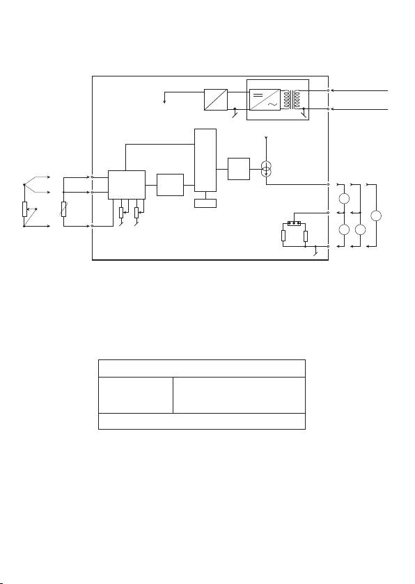
Descriptions of Input / Output and supply connections are shown in the block
diagram and side label.
The following apply to fixed hazardous voltages-connected devices:
The max. size of the protective fuse is 10 A and, together with a power switch, it
should be easily accessible and close to the device.
The power switch should be marked with a label telling it will switch off the voltage to the device.
CALIBRATION AND ADJUSTMENT
During calibration and adjustment, the measuring and connection of external voltages must be carried out according to the specifications of this manual.
The technician must use tools and instruments that are safe to use.
NORMAL OPERATION
Operators are only allowed to adjust and operate devices that are safely fixed in
panels, etc., thus avoiding the danger of personal injury and damage. This means
there is no electrical shock hazard, and the device is easily accessible.
CLEANING
When disconnected, the device may be cleaned with a cloth moistened with distilled water.
LIABILITY
To the extent the instructions in this manual are not strictly observed, the customer cannot advance a demand against PR electronics A/S that would otherwise exist
according to the concluded sales agreement.
4 2202V107-UK
Page 7
HOW TO DISMANTLE SYSTEM 2200
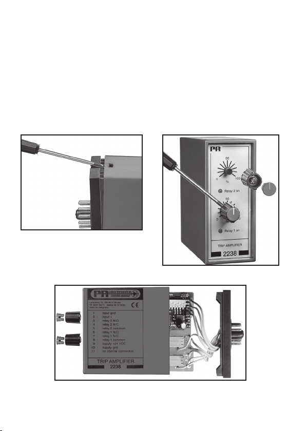
The back panel of the device is detached from the housing by way of a screw-driver
as shown in picture 1.
On a device with knobs, these may have to be removed before the PCB can be
taken out as shown in picture 2.
After this, the back panel can be pulled out together with the PCB, but please
notice the position of the PCB as there is a number of different positions in the
house. Do not pull the wires unnecessarily, instead pull the PCB, see picture 3.
Switches and jumpers can now be moved.
When assembling the back plate and housing, please make sure no wires are stuck.
Picture 1: Dismantlement of back plate
and housing.
Picture 2: Removal of knobs.
Picture 3: Removal of PCBs for adjustment of DIP switches
and replacement of jumpers.
2202V107-UK 5
Page 8

R/I TRANSMITTER 2202
• Input for Pt100, Ni100 or Ohm
• Sensor cable compensation
• Linearised analogue output
• 24 VDC or universally supplied
• Individual 0 and 100% adjustment
• DIN rail mounting on a standard 11-pole relay socket
Application
Electronic temperature measurement with a Pt100...Pt1000 or a Ni100...Ni1000
sensor. • Conversion of a linear resistance change to a standard analogue current / voltage signal from e.g. valves or linear movements with attached potentiometer. • As signal simulator via externally mounted 10-turn potentiometer.
• Suit able in applications with potentiometers that are not fully utilised as the 0
and 100% adjustments on the front can be adjusted individually without interacting.
Technical characteristics
General
The unit is built around a microprocessor core with an efficient program operation.
The supply voltage may be ordered to 24 VDC or with a universal supply of
24...230 VAC and 24...250 VDC with galvanic isolation between supply and input /
output ground. The adjust ment range for the 0 and 100% trimmers has a standard
set-up for ±2.5% of span, but the device may be ordered with an adjustment range
of up to ±25%. The sensor connection is always a 3-wire connection with cable
compensation for up to 10 Ω in each wire. If a 2-wire connection is re quested pins
7 and 6 must be short-circuited in the socket (no cable compensation).
Input
Pt100 temperature input according to the norm IEC 751 within the range
-200...+850°C. Ni100 temperature input according to the norm DIN 43760 within
the range -50...+250°C. Linear resistance input within the range 0...10 kΩ.
The measurement range should be specified when placing the order, e.g.
0...150°C. The min. span is 50°C for the RTD input; for linear resistance the min.
span is 30 Ω. The RTD input can be delivered as multiples of the main type
(e.g. Pt100 x 10 = Pt1000). The input can be reversed so that 0% e.g. is 150°C
and 100% is 0°C.
6 2202V107-UK
Page 9

Output
Analogue standard current / voltage output of 0/4...20 mA / 0/2...10 VDC. The output signal is proportional and linear to the value of the temperature or resist ance
value that influences the input. Special current or voltage signals can be ordered.
The max. load of the current output is 600 Ω. The minimum load of the voltage
output is 500 kΩ. Also, a number of different sensor error detection meth ods are
offered, for instance Upscale ≥ 23 mA.
Electrical specifications
Specifications range:
-20°C to +60°C
Common specifications:
Supply voltage, DC .................................................. 19.2...28.8 VDC
Supply voltage universal ...................................... 21.6...253 VAC
50...60 Hz
19.2...300 VDC
Internal consumption, 2202_ _ D ...................... ≤ 0.9 W
Internal consumption, 2202 _ _ P
(universally supplied) ............................................. ≤ 1.4 W
Isolation, test / operation (2202 _ _ P) .......... 3.75 kVAC / 250 VAC
Signal / noise ratio .................................................. Min. 60 dB
Signal dynamics, input ........................................... 17 bit
Signal dynamics, output ....................................... 16 bit
Response time (0...90%/100...10%) ................ < 165 ms
Calibration temperature ........................................ 20...28°C
Temperature coefficient:
span < 100°C ........................................................ < ±0.01°C /°Camb.
span > 100°C ........................................................ < ±0.01% of span /°Camb.
Linearity error ........................................................... < ±0.1% of span
EMC immunity influence ....................................... < ±0.5%
Relative air humidity .............................................. < 95% RH (non-cond.)
Dimensions (HxWxD) .............................................. 80.5 x 35.5 x 84.5 mm
Protection degree .................................................... IP50
Weight DC / universally supplied ...................... 100 g / 150 g
Input:
Type
Pt100
Ni100
Lin. R
Min.
value
-200°C
-50°C
0 Ω
Max.
value Min. span Standard
+850°C
+250°C
10 kΩ
50°C
50°C
30 Ω
IEC 751
DIN 43760
-
2202V107-UK 7
Page 10

Max. offset ................................................................. 50% of max. value
Adjustment acc. to order ...................................... ±2.5...±25% of span
Cable resistance per wire max. .......................... 10 Ω
Sensor current ........................................................... > 0.2 mA, < 0.4 mA
Basic accuracy ........................................................... < ±0.3°C
Output:
Signal range ............................................................... 0...20 mA / 0...10 VDC
Min. signal range ...................................................... 5 mA / 250 mV
Max. offset ................................................................. 50% of max. value
Load (max.) ................................................................. 20 mA / 600 Ω / 12 VDC
Load stability ............................................................. < ±0.01% of span / 100 Ω
Sensor error detection ........................................... Upscale / Downscale
Current limit ............................................................... ≤ 28 mA
Observed authority requirements: Standard:
EMC 2004/108/EC .................................................. EN 61326-1
LVD 2006/95/EC (2202 _ _ P) ........................... EN 61010-1
EAC TR-CU 020/2011............................................. EN 61326-1
Of span = Of the presently selected range
Order: 2202
Type Input Output Supply
2202
Pt100
Ni100
Lin. R
Special
: L
: N
: R
: X
Special
0...20 mA
4...20 mA
0...5 mA
0...1 V
0,2...1 V
0...10 V
2...10 V
: 0
24 VDC
: 1
24...230 VAC &
: 2
24...250 VDC
: 3
: 4
: 5
: 6
: 7
8 2202V107-UK
: D
: P
Rnge
Acc. to orderr
Page 11
BLOCK DIAGRAM
Universal sup. only
DC
V +
D / A
0...20
mA
JP 1 JP 2
50050
Lin.R
Input +
Comp. +
RTD
Input -
V +
DC
CPU
7
6
5
0% 100%
MUX
A / D
EEPROM
2202
For 2-wire connection pins 6 and 7 must be short-circuited in the socket.
Voltage output
JP1 ON
JP2 ON
Short-circuit pins 3 and 2, V+ = 2, V- = 1
0/0.2...1 VDC
0/2...10 VDC
Supply (+) & P
9
24
VDC
10
Supply (Gnd) & N
I +
3
V +
2
Gnd.
1
Or
I + V
OutIOutVOut
VAV
24...230 VAC &
24...250 VDC
A
2202V107-UK 9
Page 12
Displays
of inputs and outputs for display of temperature, volume and
weight, etc. Feature linearization, scaling, and dierence
measurement functions for programming via PReset software.
Programmable displays with a wide selection
Ex interfaces
as HART signals between sensors / I/P converters / frequency
signals and control systems in Ex zone 0, 1 & 2 and for some
devices in zone 20, 21 & 22.
Isolation
signals as well as HART signals. A wide product range with both
loop-powered and universal isolators featuring linearization,
inversion, and scaling of output signals.
Temperature
B mounting and DIN rail devices with analog and digital bus
communication ranging from application-specific to universal
transmitters.
Universal
universal options for input, output and supply. This range oers
a number of advanced features such as process calibration,
linearization and auto-diagnosis.
Interfaces for analog and digital signals as well
Galvanic isolators for analog and digital
A wide selection of transmitters for DIN form
PC or front programmable devices with
Page 13
www.prelectronics.fr
[email protected]
www.prelectronics.de
[email protected]
www.prelectronics.es
[email protected]
www.prelectronics.it
[email protected]
www.prelectronics.se
[email protected]
www.prelectronics.com
[email protected]
www.prelectronics.com
[email protected]
www.prelectronics.cn
[email protected]
www.prelectronics.be
[email protected]
Head oce
Denmark www.prelectronics.com
PR electronics A/S [email protected]
Lerbakken 10 tel. +45 86 37 26 77
DK-8410 Rønde fax +45 86 37 30 85
 Loading...