

Page 1
P r e c i s i o n F l i g h t C o n t r o l s , I n c .
C A T I I I U S B M o d e l S y s t e m S e t u p G u i d e
Page 2

Preface
This setup guide will walk you through the necessary steps to setup your CAT III System Upgraded to
USB Model with X-Plane 9.xx. If you system was not upgraded to USB, or was a complete USB system, please
refer to the guide that you received for your system.
CAT III System upgraded to USB includes:
Cirrus 2 Professional with Hardware Controller 3 upgraded to USB.
Digital Avionics connected via 9 Pin serial port.
Cirrus Rudder Pedals connected to the C2 Professional rudder input.
There are 5 Phases of setup:
A. Installation of PFC USB HID plugin
B. Installation of PFC Utilities
C. Hardware Calibration in Windows
D. Axis Assignment in X-Plane
E. Calibration in X-Plane.
Installation of PFCUSBHID PLUGIN for X-PLANE 9.XX
The PFCUSBHID plugin, is the software makes USB manufactured by Precision Flight Controls, Inc work with
X-Plane 9.xx. The USB device support is limited to the following devices: Cirrus II, Cirrus 2 Professional, Digital
Avionics Panel, Modular Flight Deck (MFD), Modular Flight Deck Desktop and Modular Flight Deck G1000.
If you are using our serial device/s, please do not install this as they are not compatible. This guide
assumes that you have installed the X-Plane 9.xx. Please refer to your software manual for software
installation.
1. Insert the CD for the PFCUSBHID plugin.
2. Look for the PFCUSBHID_plugin_XP9.4RC14.exe and double click on it.
3. Click on Next
Page 3
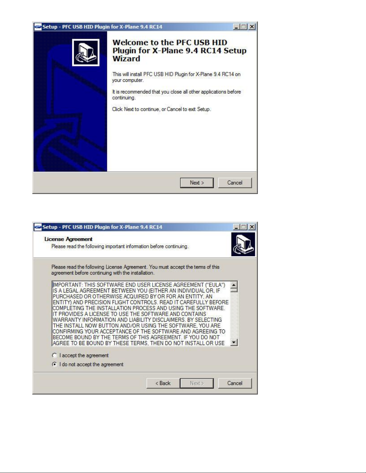
4. Read through the license agreement. You will need to Accept the agreement to be able to use the
plugin. Once you have agreed click on Next.
Page 4
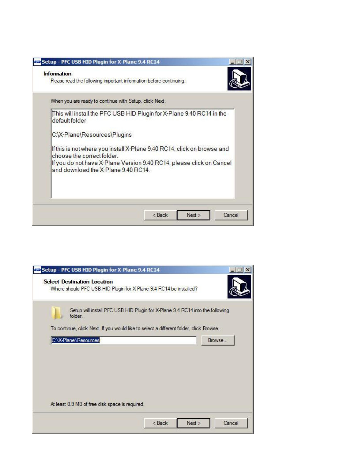
5. This explains that the plugin will be installed on the default location of C:\X-Plane\Resources\plugins.
If you did not install X-Plane in the default directory above you will need to point the installer to that
location in the next step.
6. If you installed X-Plane in the default location, click next here. If not click on browse and choose the
folder X-Plane is installed in.
Page 5
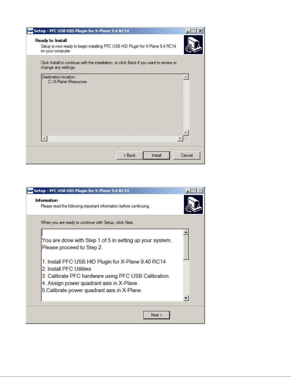
7. Click on the Install to start installation.
8. Now click on Next.
Page 6
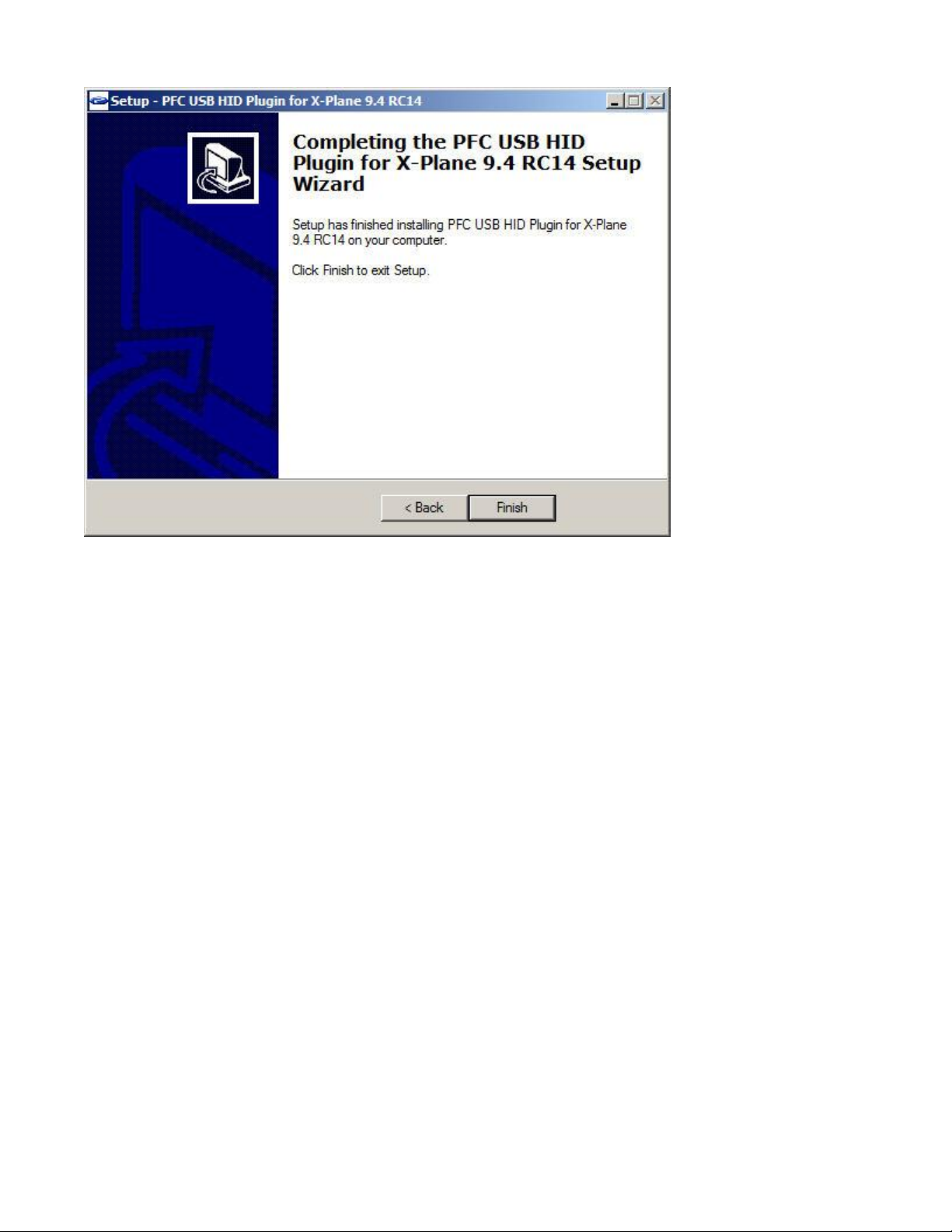
9. Now click on Finish.
Page 7
USB Utilities Installation Guide
The PFC USB Utilities is a combination of software that you can use to test and calibrate the different
Precision Flight Controls, Inc. USB consoles. The USB device support is limited to the following devices: Cirrus II,
Cirrus 2 Professional, Digital Avionics Panel, Modular Flight Deck (MFD), Modular Flight Deck Desktop and
Modular Flight Deck G1000. The utilities package includes the items below including the description:
PFC Test GUI – Used for testing the USB Cirrus II, USB Cirrus 2 Professional, USB Modular Flight Deck
PFC Hardware Calibration – Used for calibrating the different axis of the console above.
If you are using our serial device/s, please do not install this as they are not compatible.
Installation
10. Insert the CD for the PFC USB UTILITIES.
11. Look for the PFCUSBUTILITIES.exe and double click on it.
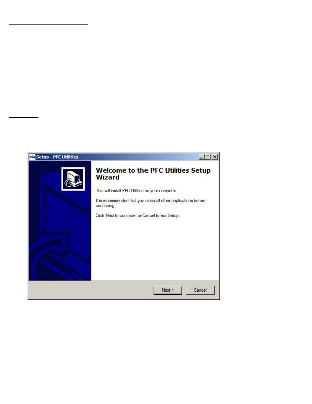
12. Click on Next
Page 8
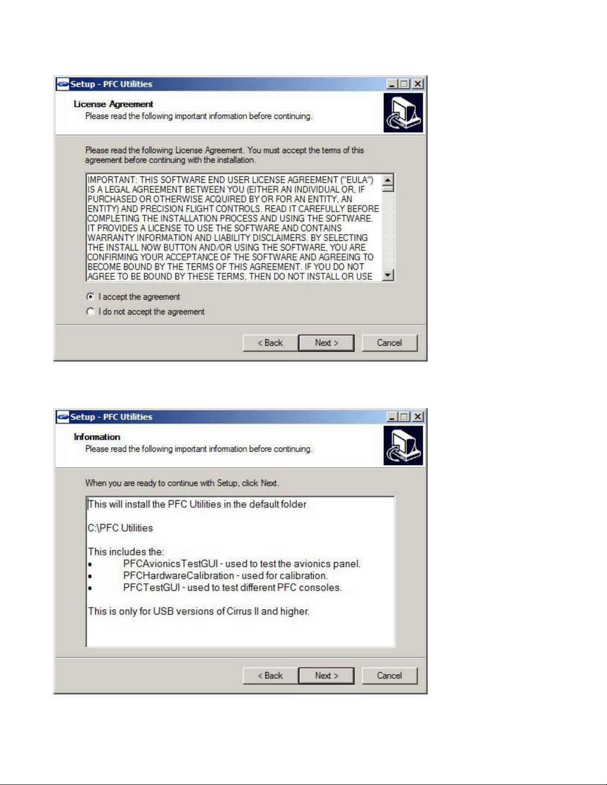
13. Read through the license agreement. You will need to Accept the agreement to be able to use the
PFC Utilities. Once you have agreed click on Next.
14. This explains that the PFC Utilities will be installed in C:\PFC Utilities.
Page 9
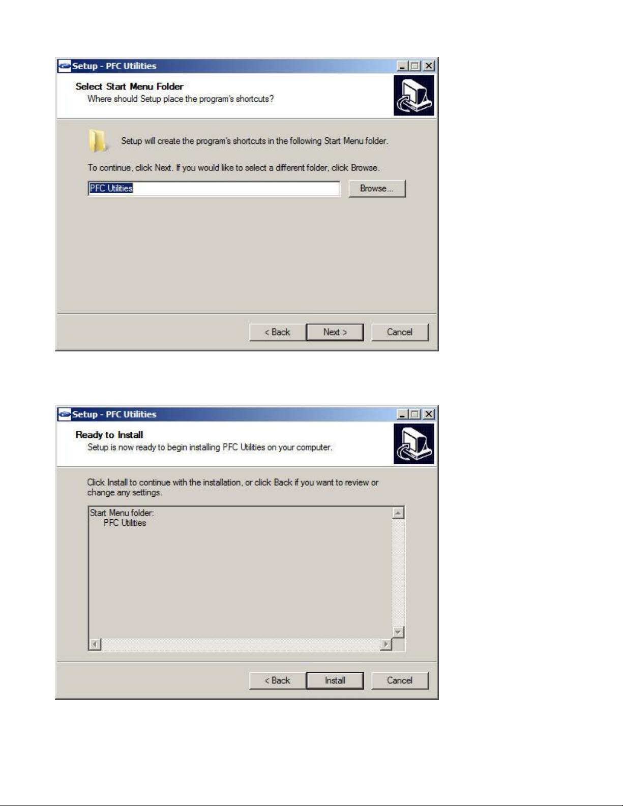
15. This explains that the PFC Utilities will be created on the Start Menu of Windows.
16. Now you are ready to install, click on the Install to start installation.
Page 10
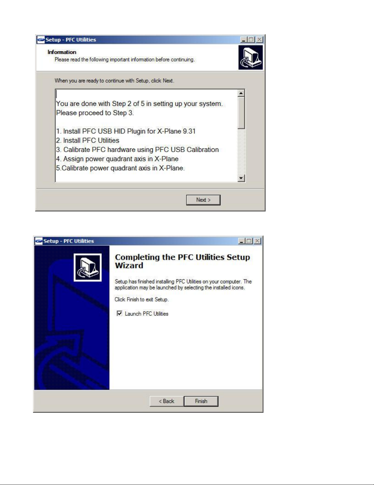
17. Now installation is done, click on Next.
18. Now click on Finish.
Page 11
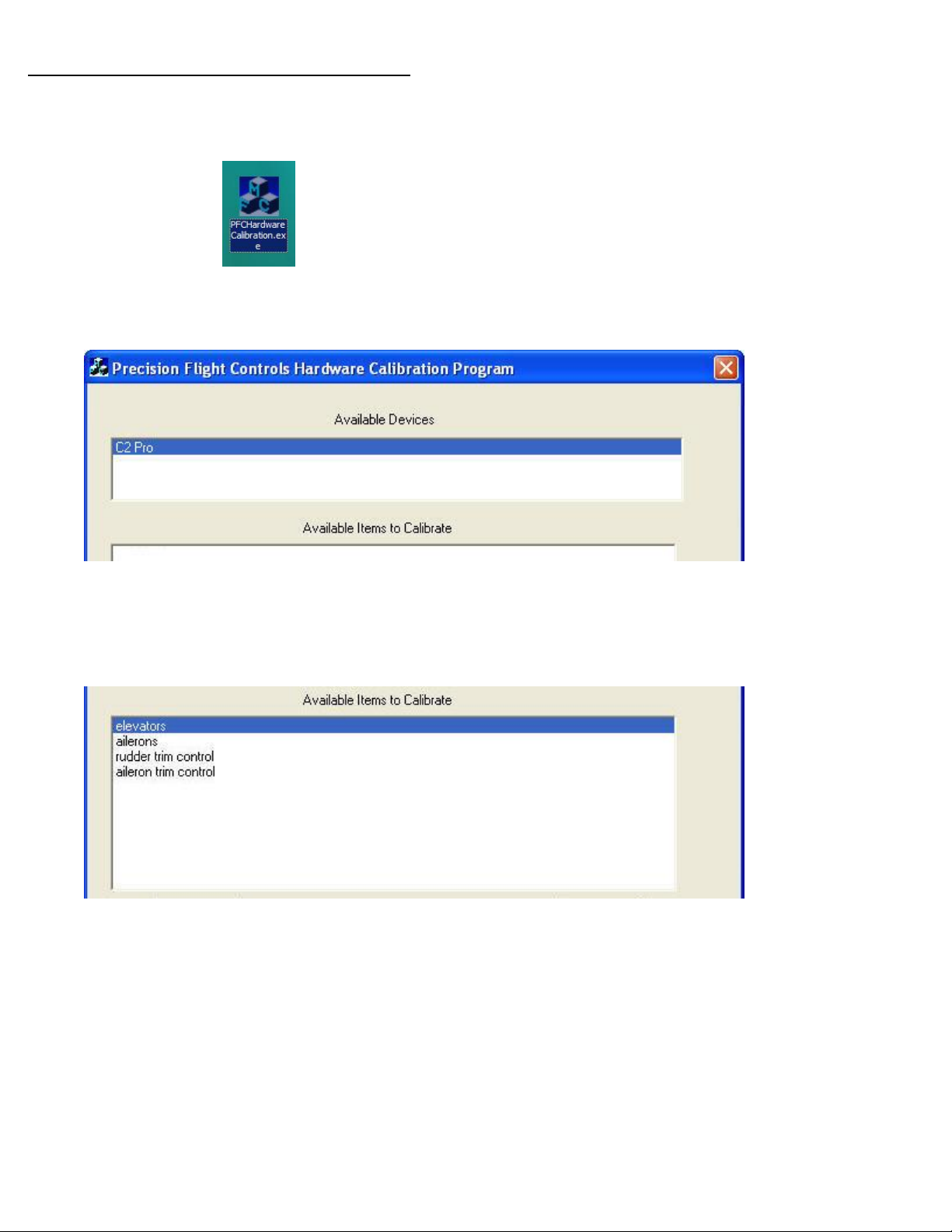
Calibration of the Cirrus 2 Professional (C2 Pro)
1. If computers are already on, make sure that X-Plane is not running
2. Go to Start then PFC, then, choose PFCHardwarecalibration.exe.
3. Under Available Devices, choose C2 Pro. After choosing this, the Available Items to Calibrate, will list
the items that can be calibrated in the C2 Pro.
4. From the Available Items to Calibrate, choose the Elevators.
Page 12
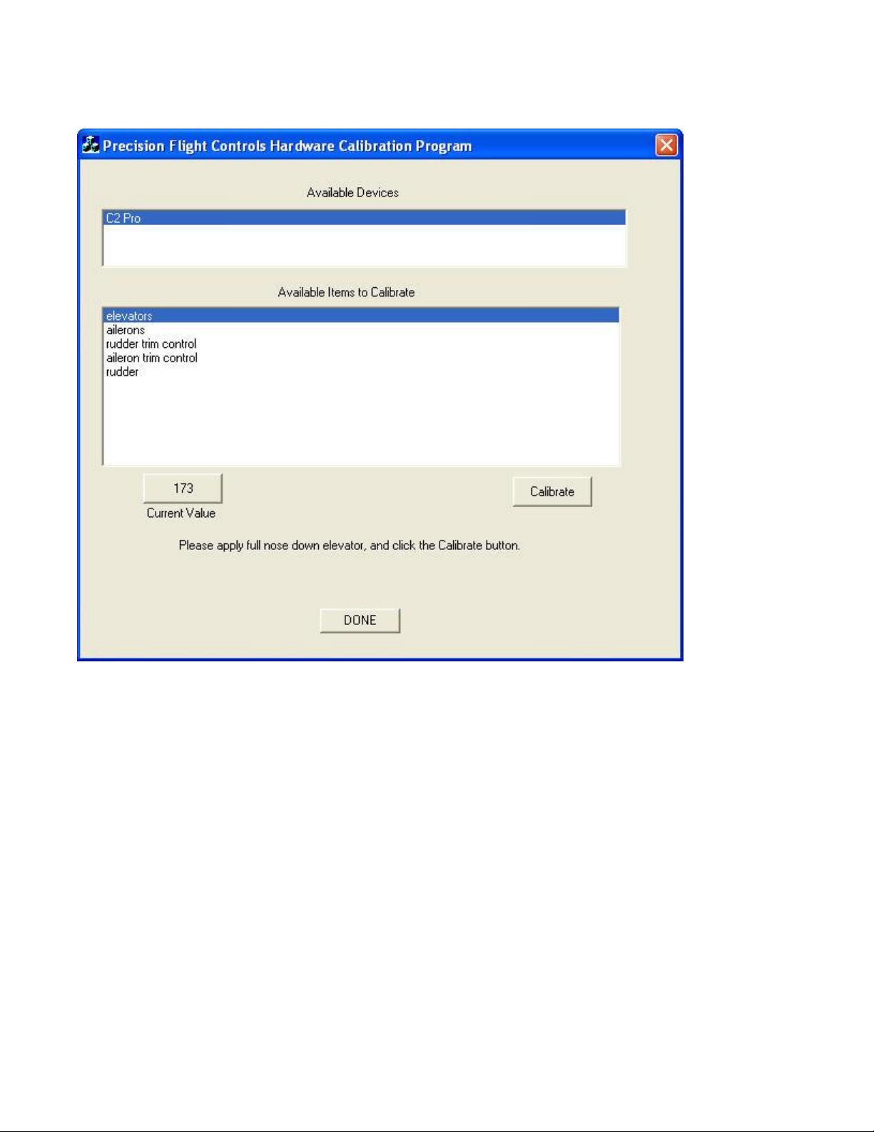
5. Notice that the calibration software is asking you to apply full nose down elevator. Push and hold the
yoke all the way forward and click on Calibrate. Also note that the Current Value will change as you
are moving your yoke back; this should go towards a lower number but will likely not reach 0.
Page 13
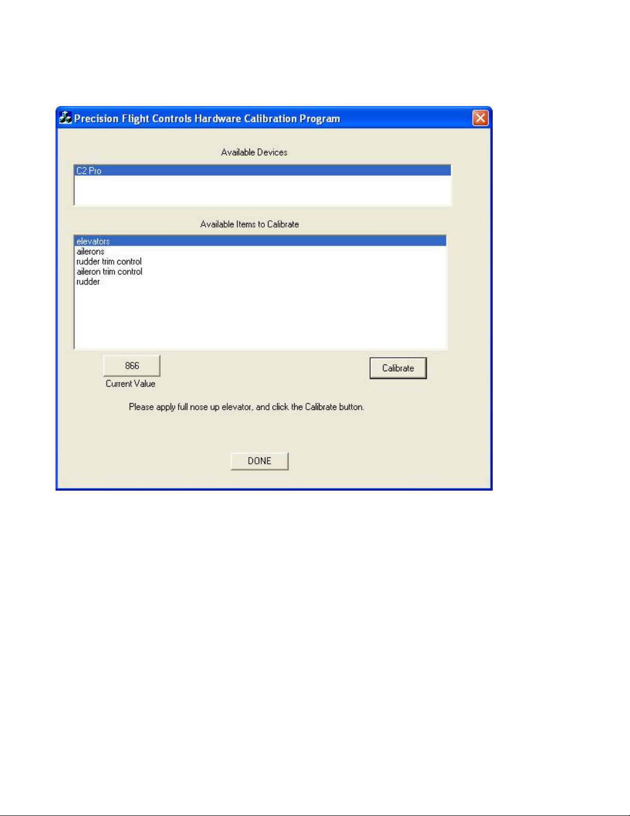
6. Once you have calibrated the full nose down position, you will now calibrate the full nose up
position. Pull and hold the yoke all the way back and click on calibrate. Notice again that the
current value will change as you are moving your yoke back; this should go towards a higher
number.
Page 14
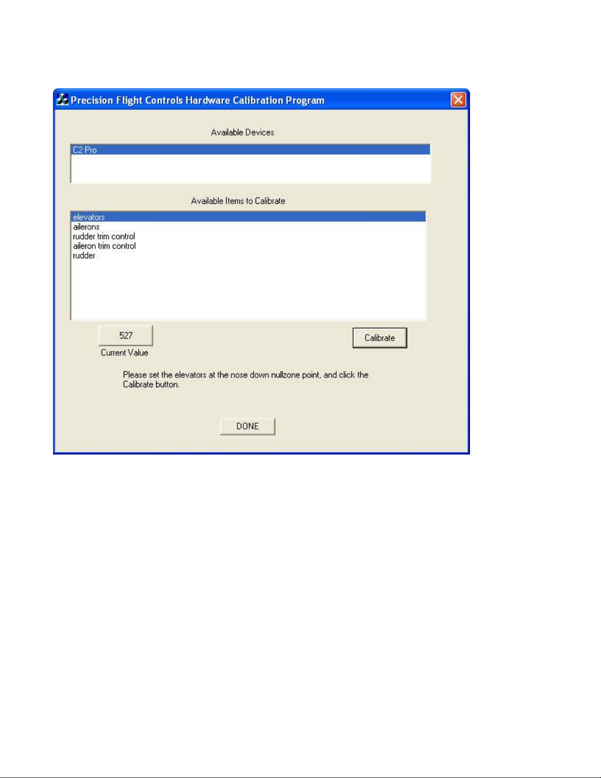
7. You will now calibrate the nose down null zone. The null zone is an area that the yoke will not have
any response, or be considered in the neutral position. To calibrate, move the yoke all the way
forward and gently release the yoke until it returns to its natural center then click on calibrate.
Page 15
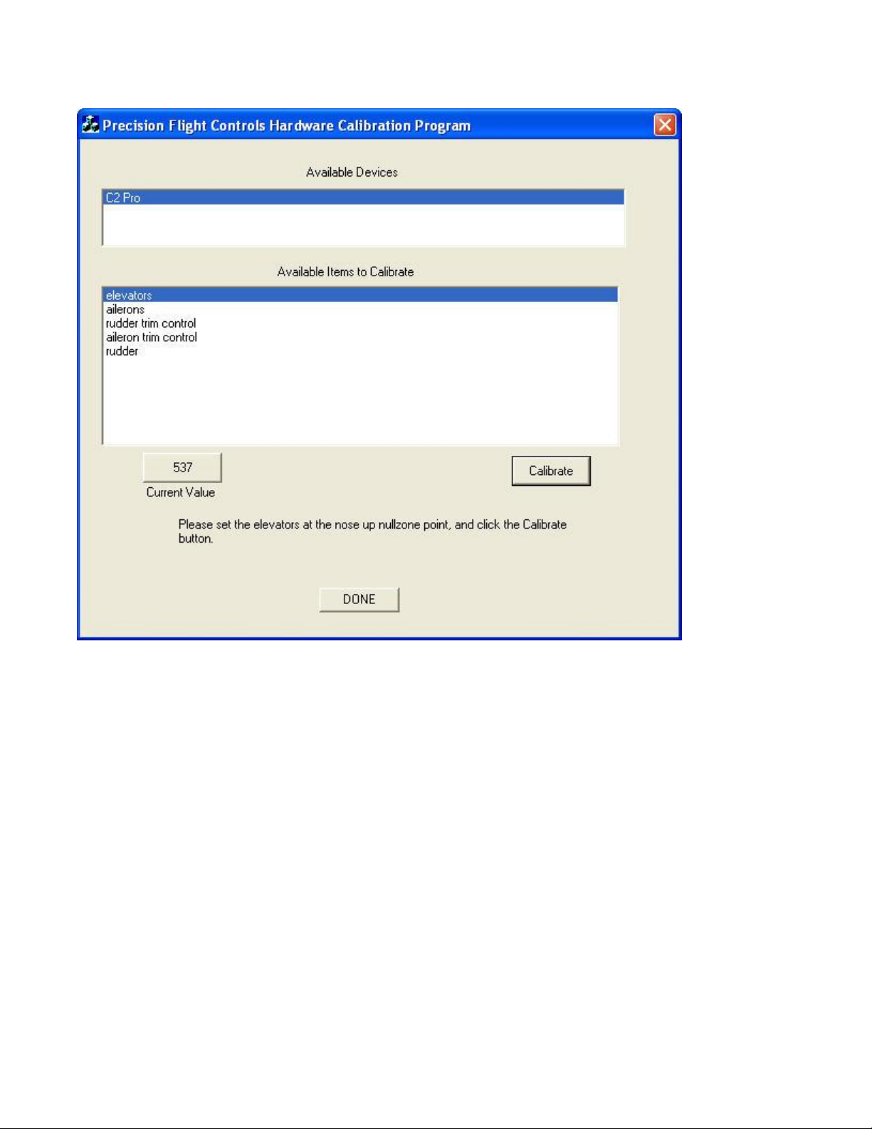
8. Next is the nose up null zone. To calibrate, move the yoke all the way back and gently release the
yoke until it returns to its natural center then click on calibrate.
Page 16
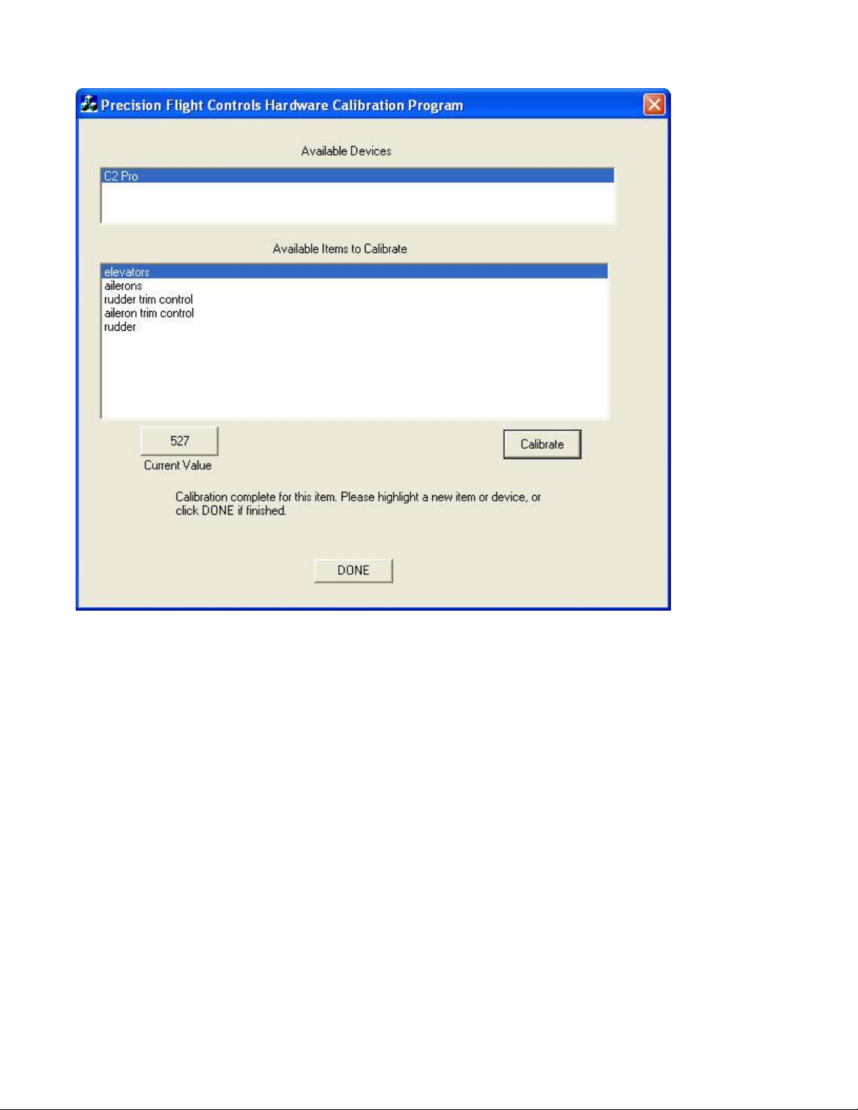
9. Now that Elevator is done, Ailerons be next. From the available items, choose.
Page 17
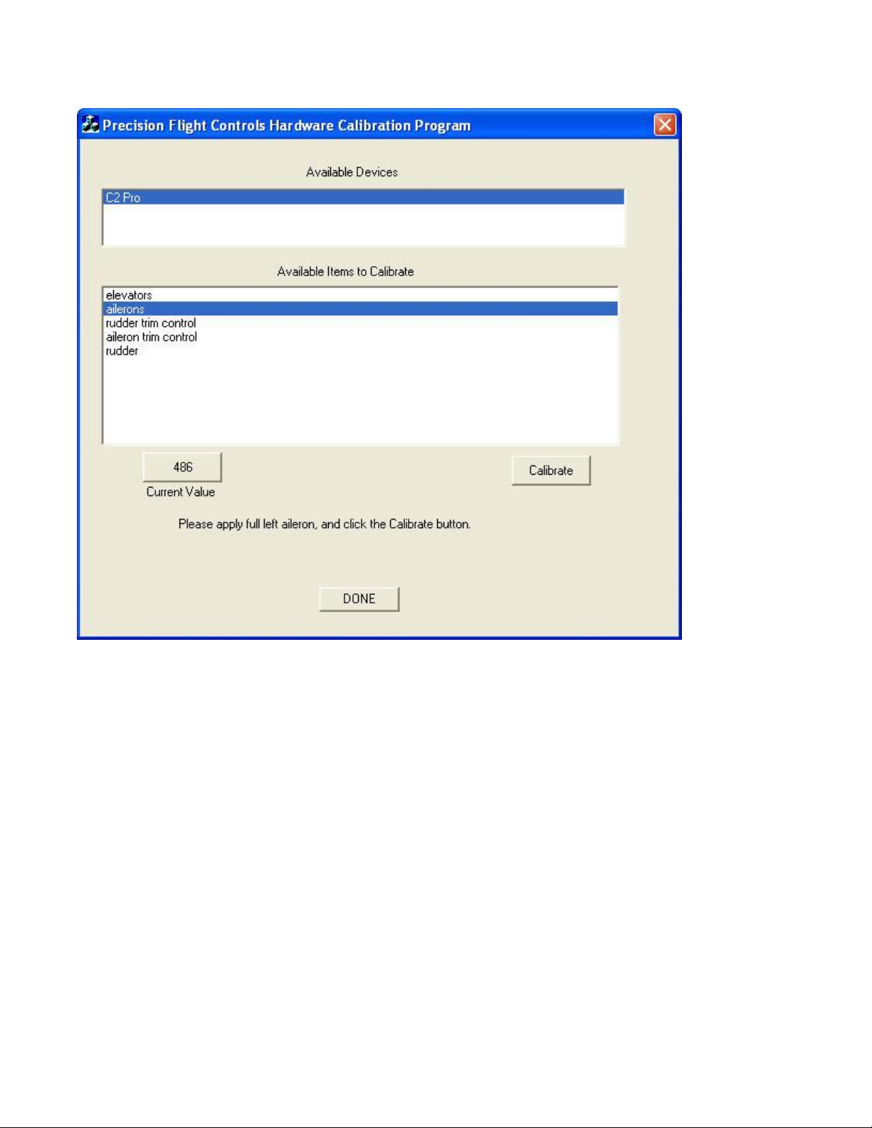
10. Once you have selected the ailerons, it will ask to apply full left aileron. Turn and hold the yoke to full
left and click on calibrate. Note the current value will change to a smaller number as you turn left.
Page 18
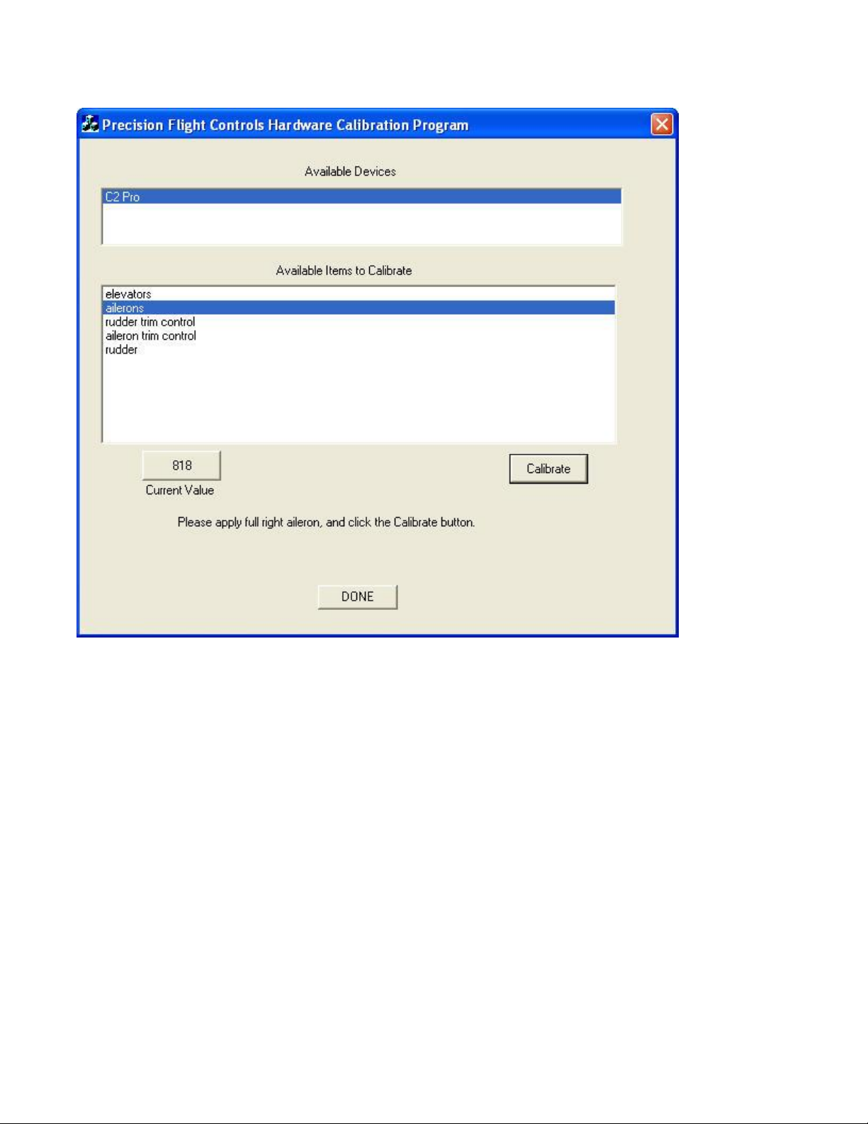
11. Now that full left is done, you will now calibrate the full right. Turn and hold the yoke all the way to the
right and click on calibrate. Note the current value will change to a higher number as you turn right.
Page 19
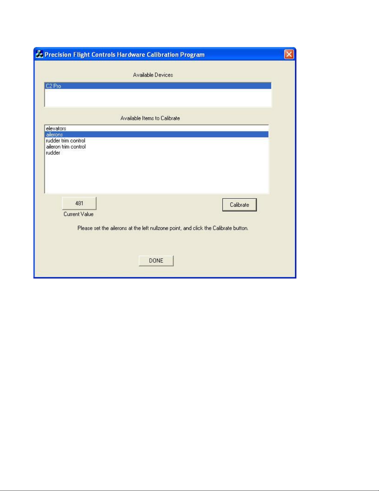
12. You will now calibrate the Left Null Zone Point. Turn the yoke all the way left and gently release the
yoke until it returns to its natural center then click on calibrate.
Page 20
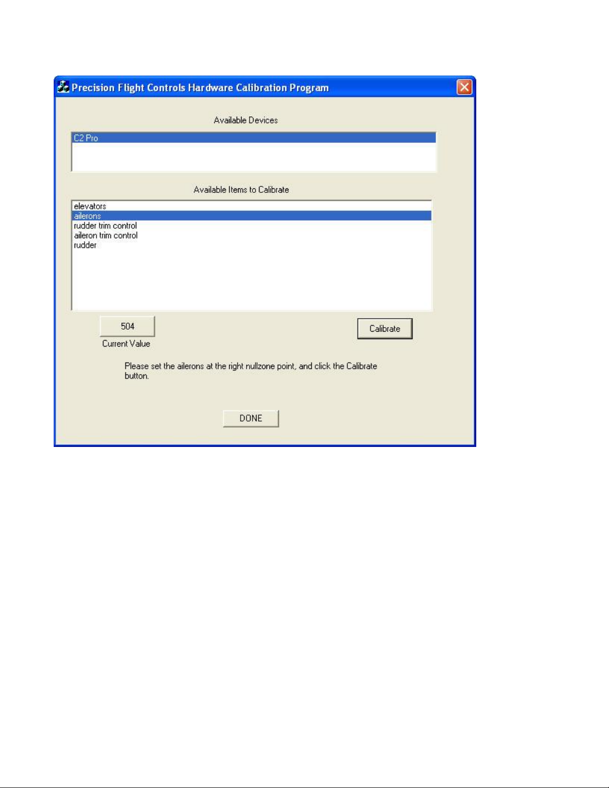
13. You will now calibrate the Right Null Zone Point. Turn the yoke all the way right and gently release the
yoke until it returns to its natural center then click on calibrate.
Page 21
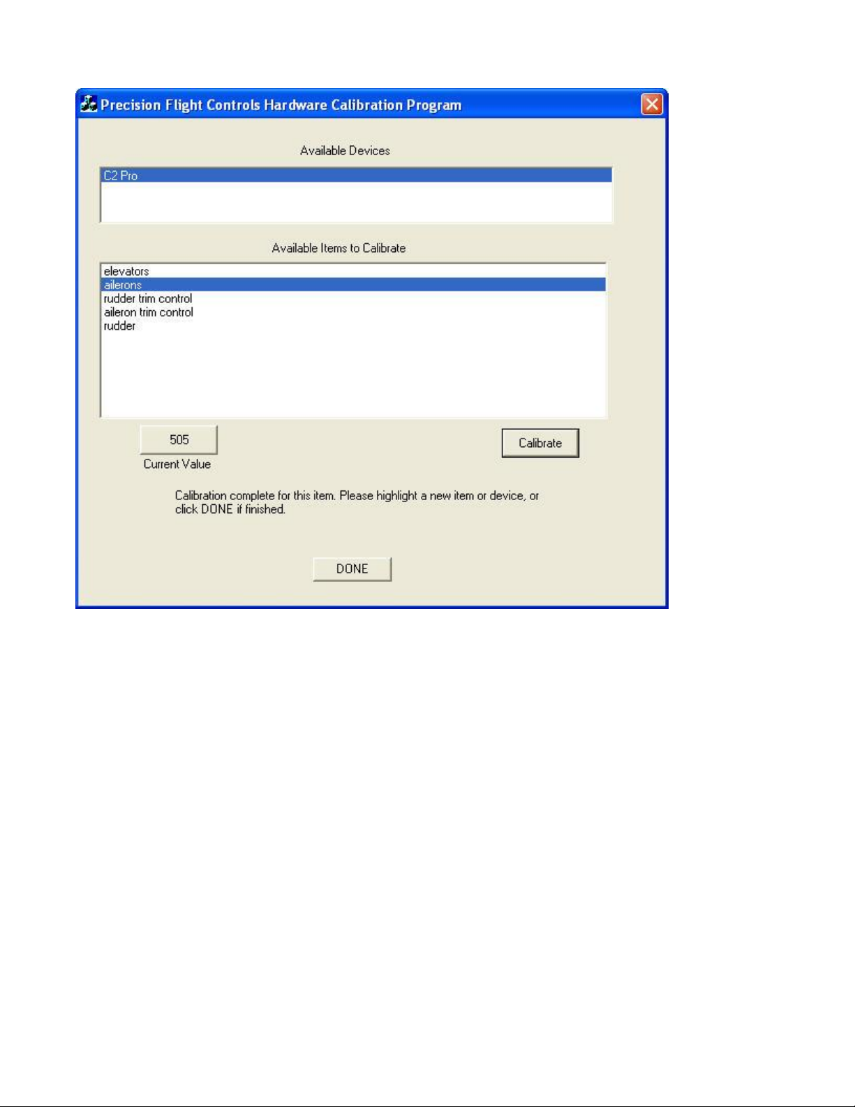
14. Choose the Rudder Trim Control from available items to calibrate.
Page 22
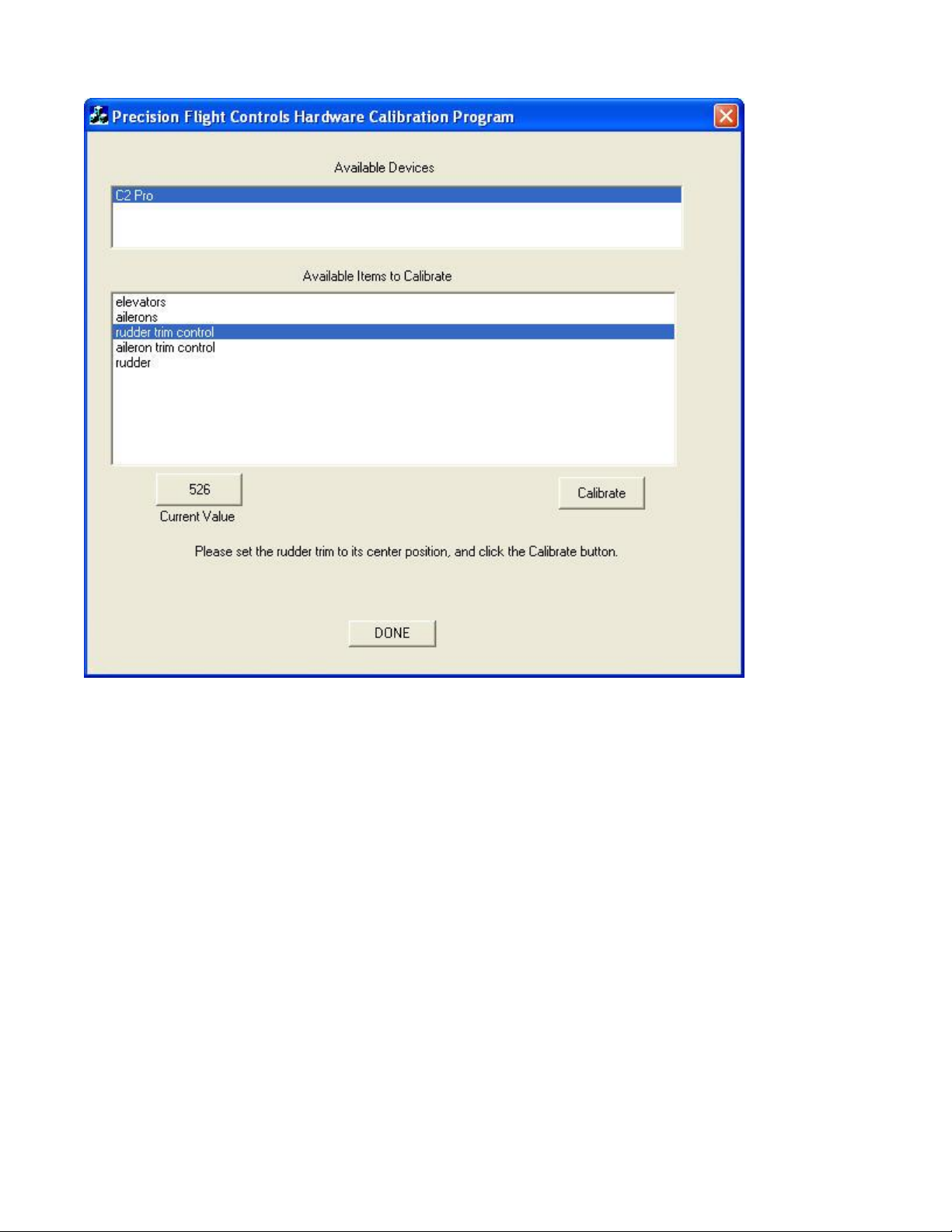
15. Once rudder trim is selected, center the rudder trim knob and click on calibrate.
Page 23
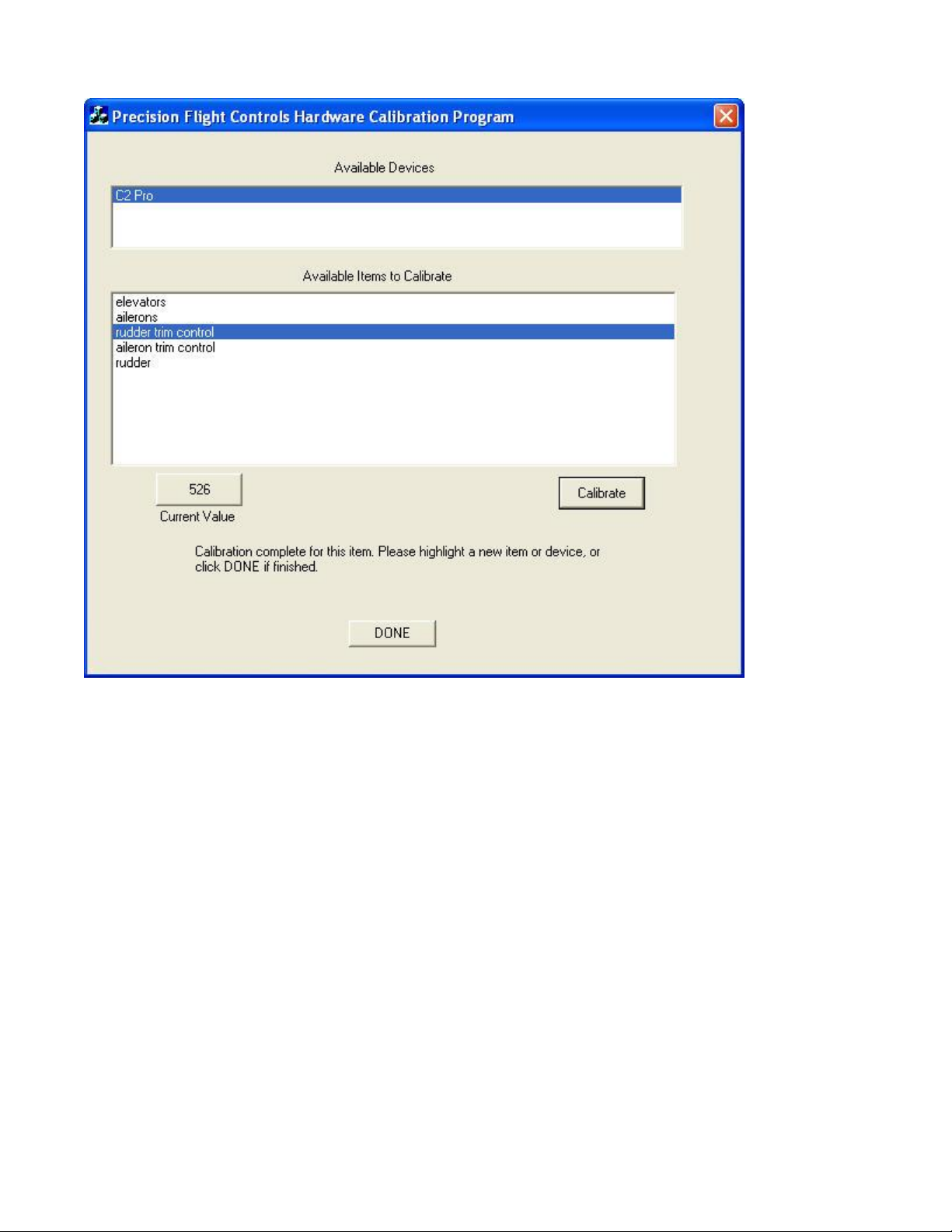
16. Choose the Aileron Trim Control next.
Page 24
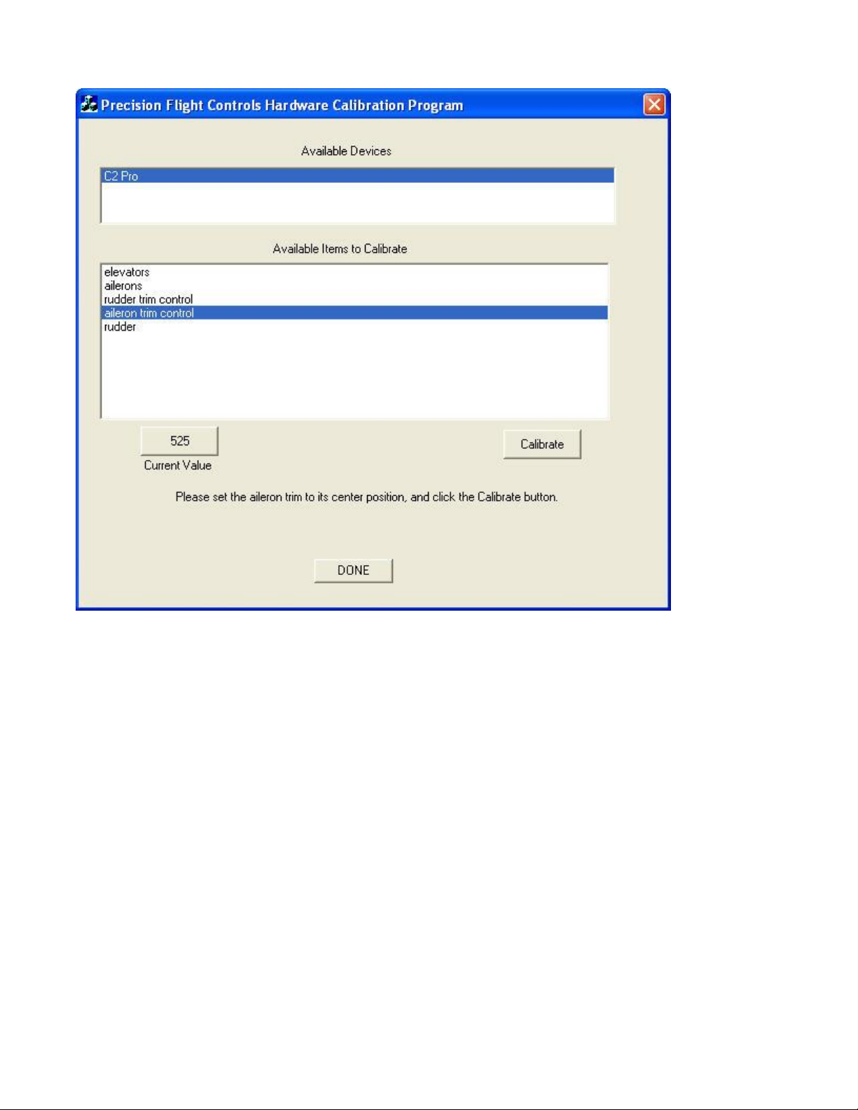
17. Once aileron trim is selected, center the aileron trim knob and click on calibrate.
Page 25
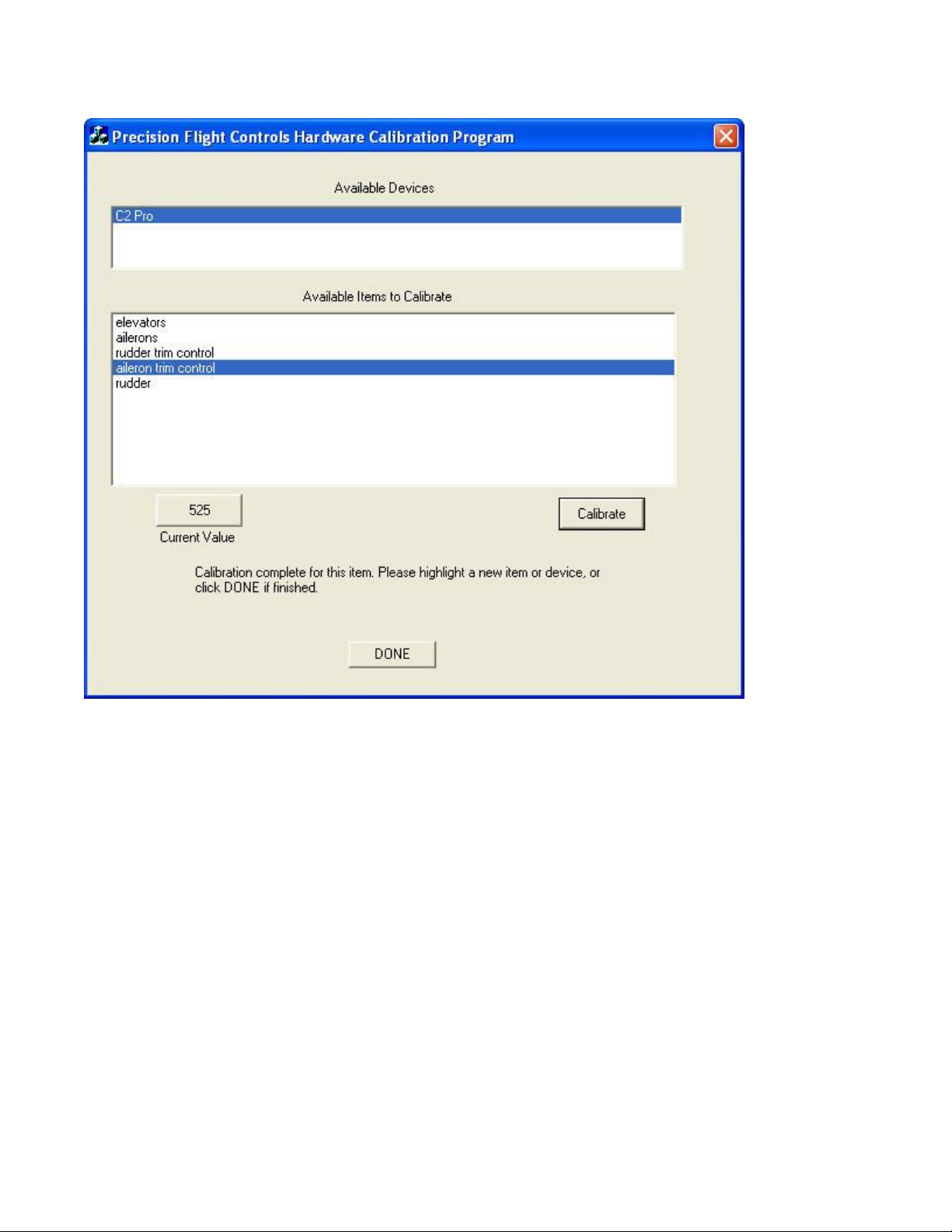
18. You are now done calibrating the Cirrus 2 Professional USB, click on Done to close the calibration
window.
Page 26
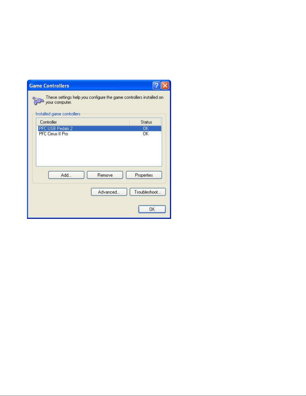
19. You will now calibrate the power quadrant in the Windows® Game Controller Screen. Please make
sure that you have a twin lever installed on the console before calibrating. If you do not have a twin
lever, you may remove you existing lever and push the rods instead. You will calibrate all six positions.
20. Click on Start on the Windows® Taskbar and then select Control Panel.
21. In the Control Panel list, select Printers and other Hardware, then double-click the Game Controllers
icon.
22. In the Game Controllers window select PFC Cirrus II Pro.
23. Note for users who have changed their XP® Desktop settings to Classic view: To test that the Cirrus
Yoke USB is functioning correctly, click on Start on the Windows® Taskbar and then select Settings
and Control Panel. In Control Panel, double-click the Game Controllers icon, and then in the Game
Controllers window select PFC Cirrus II Pro.
Page 27
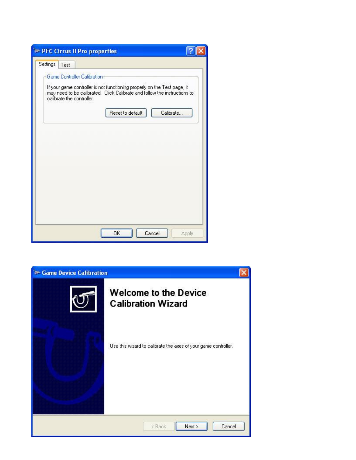
24. Next, click on Properties to open the PFC Cirrus II Pro Properties window.
25. Select Settings then Reset to default and then Calibrate.
26. Click Next on the welcome screen
Page 28
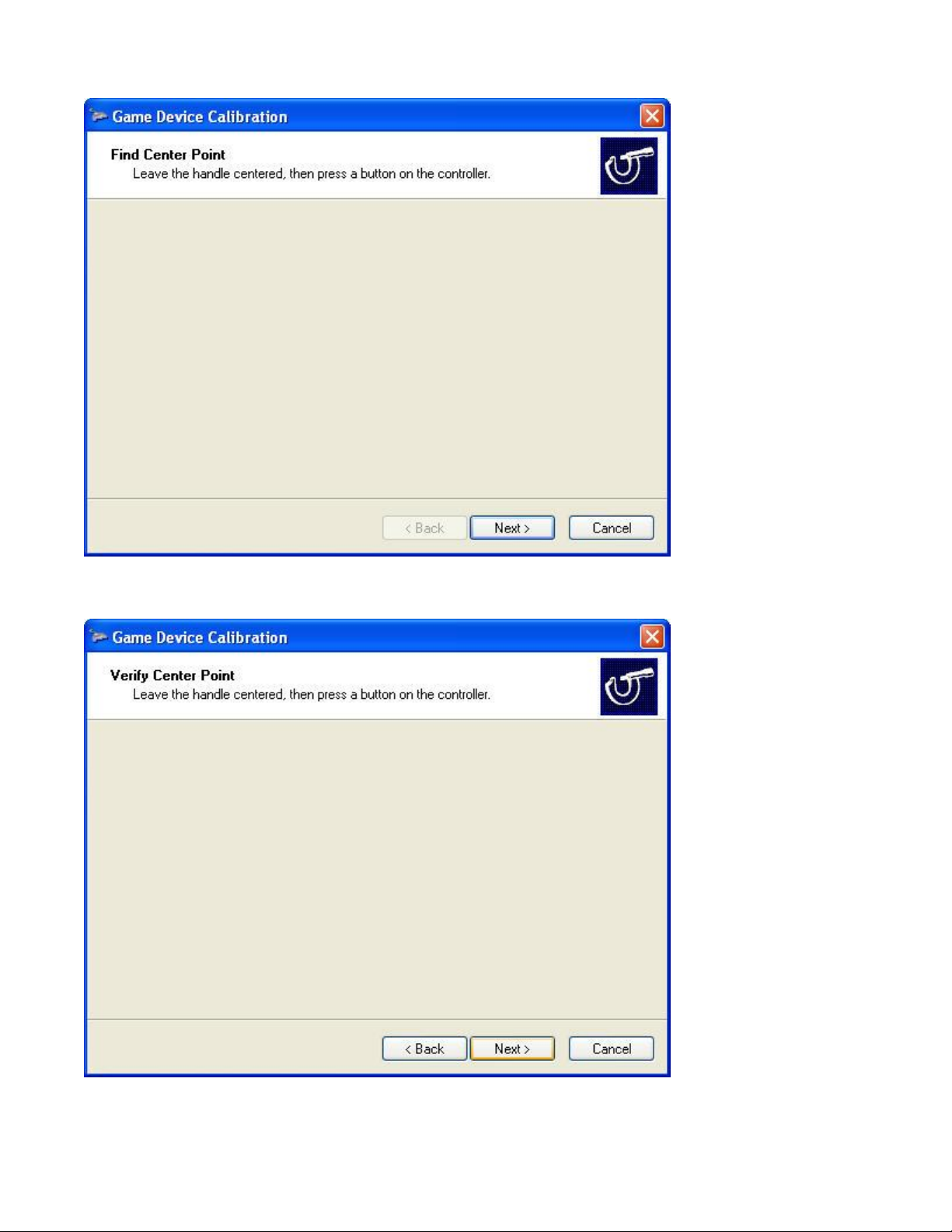
27. Click Next in the Center Point screen.
28. Click Next in the Verify Center Point screen
Page 29
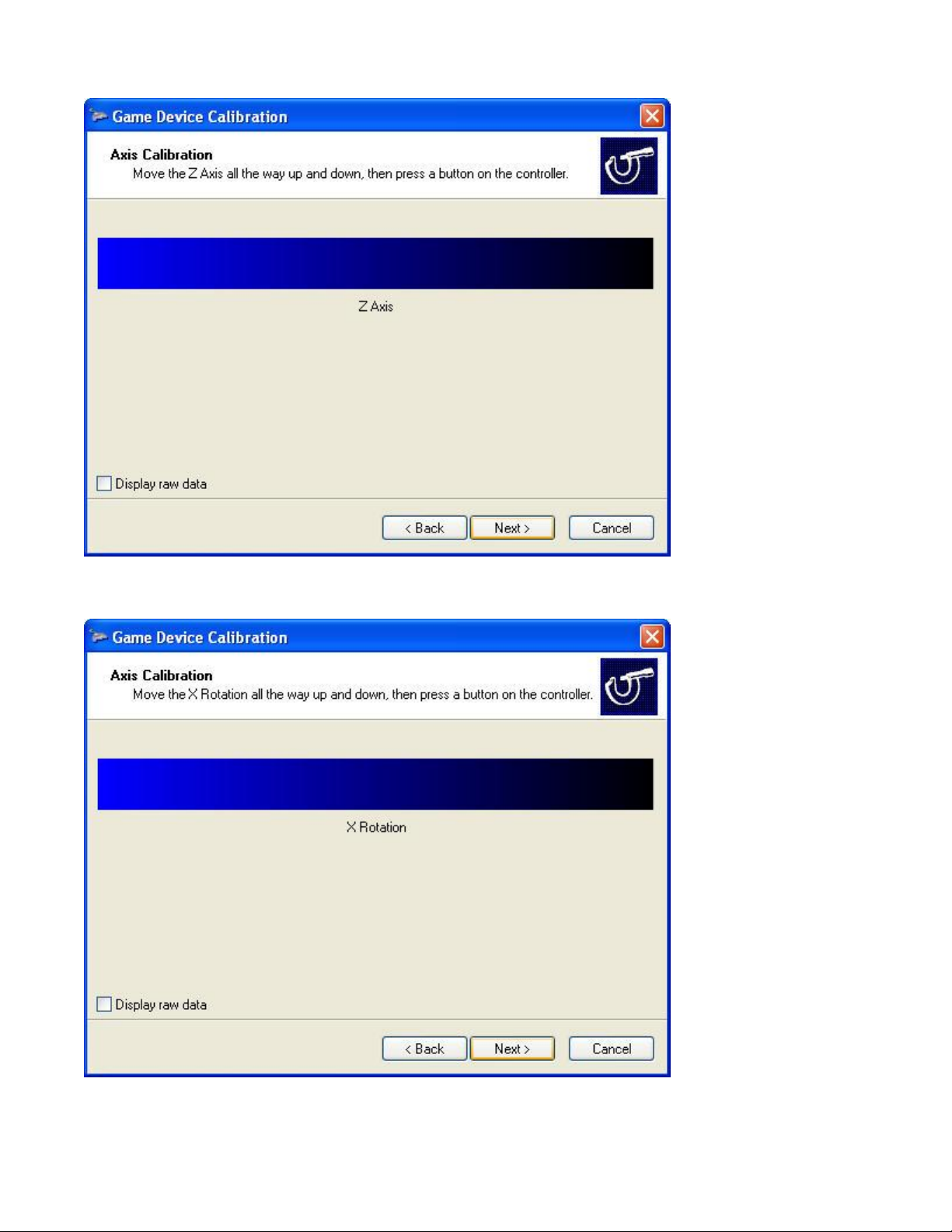
29. Move the Left Throttle from Forward and Aft few times and then click on Next.
30. Move the Right Throttle from Forward and Aft few times and then click on Next.
Page 30
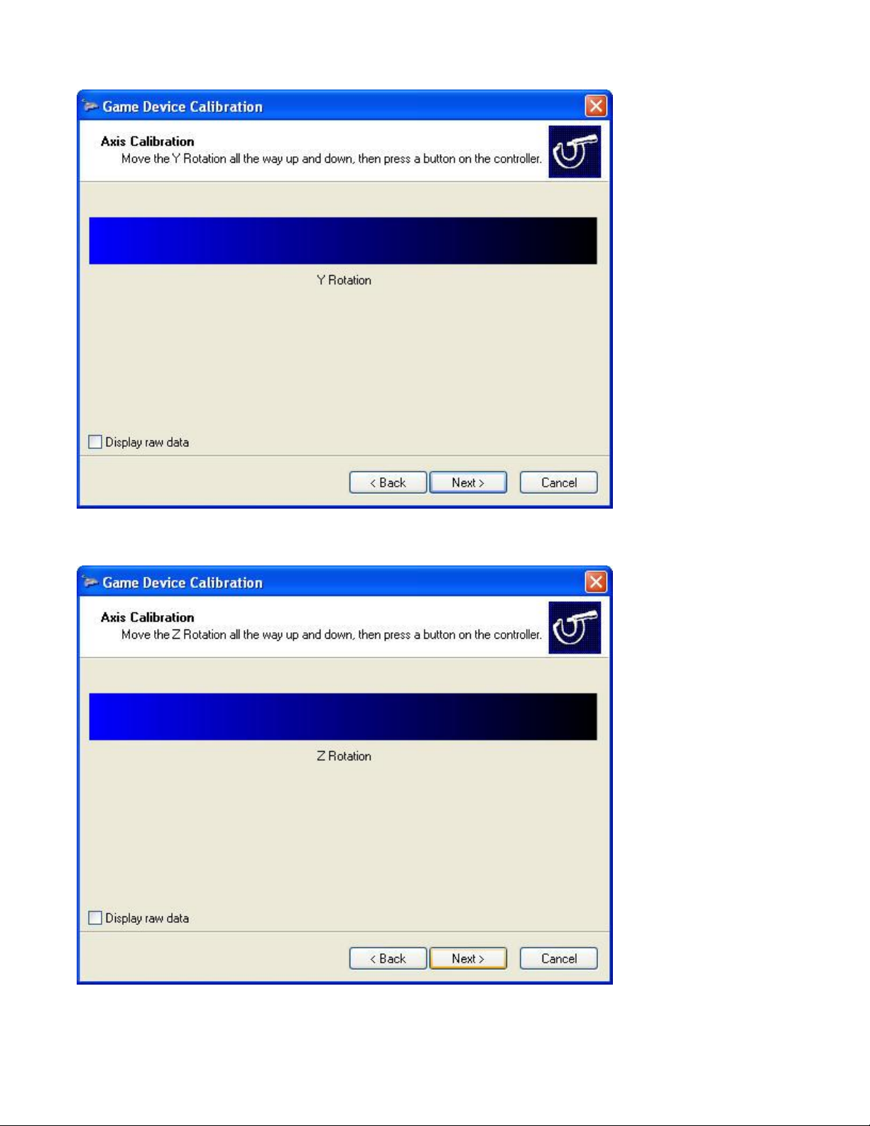
31. Move the Left Prop from Forward and Aft few times and then click on Next.
32. Move the Right Prop from Forward and Aft few times and then click on Next.
Page 31
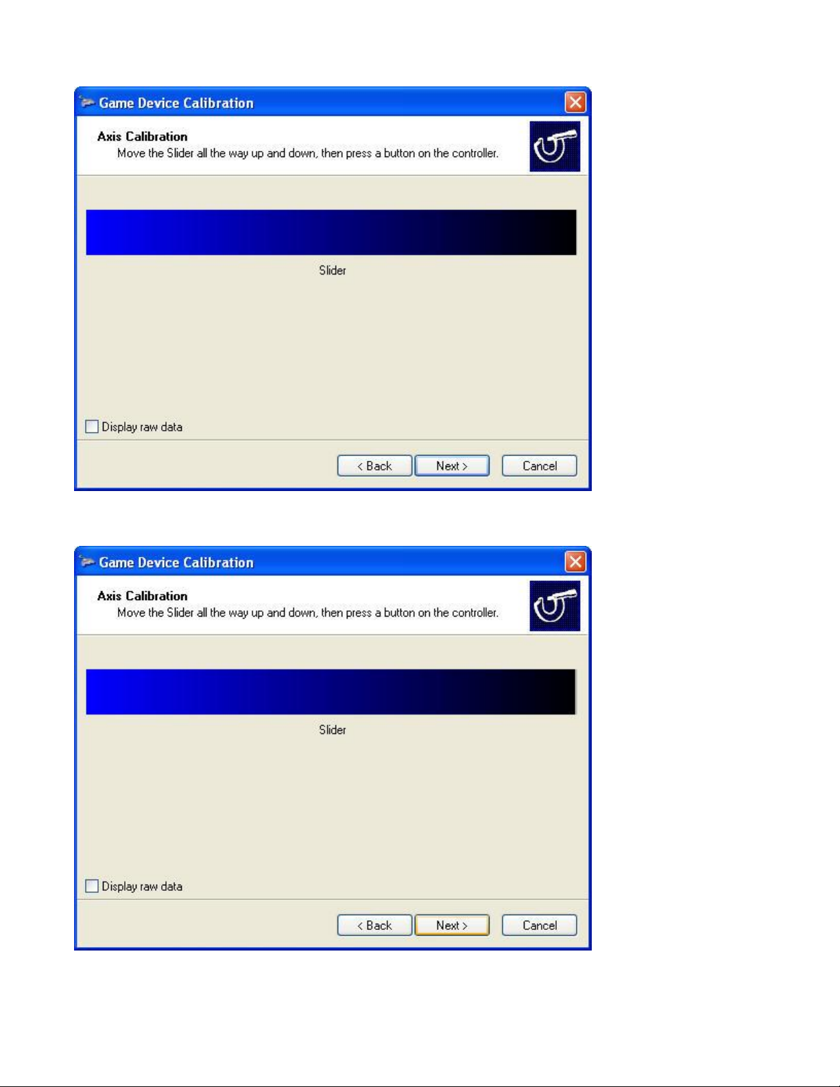
33. Move the Left Mixture from Top Forward and Aft few times and then click on Next.
34. Move the Right Mixture from Forward and Aft few times and then click on Next.
Page 32
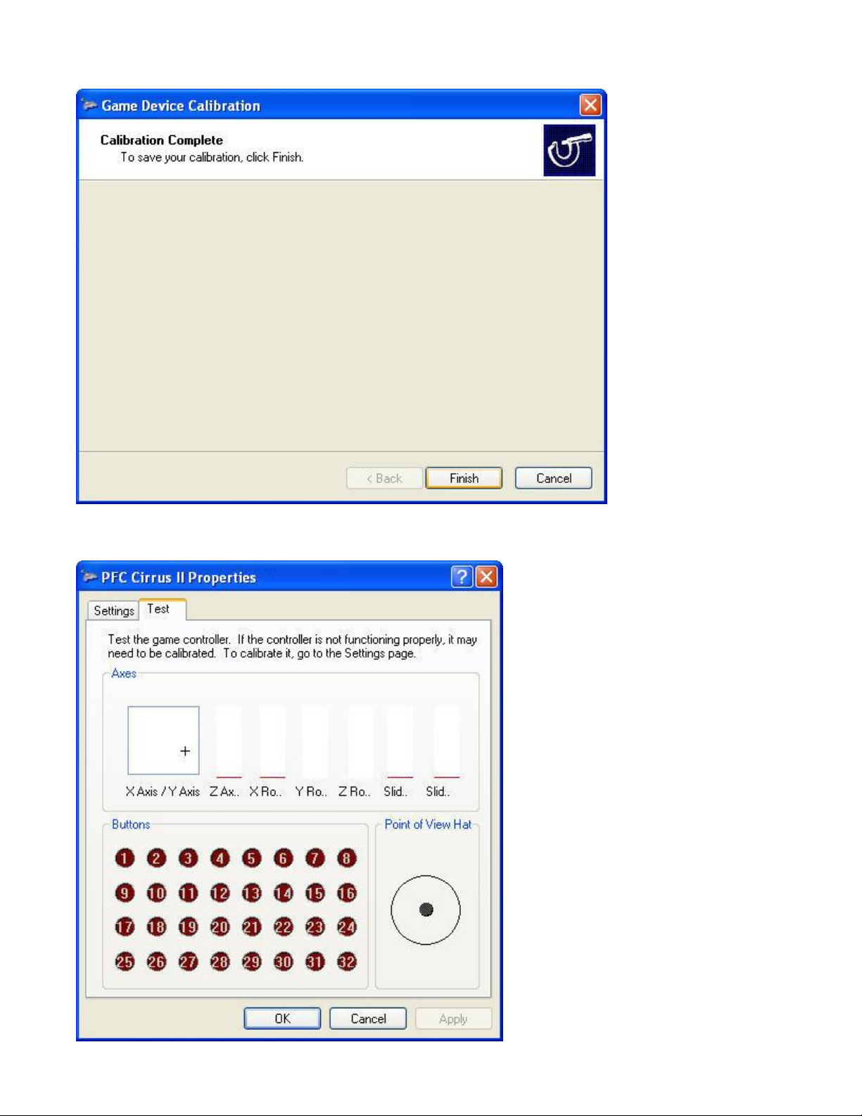
35. Now that you are done click on Finish.
36. After calibration is finished, accept the settings by clicking on the Apply button.
Page 33
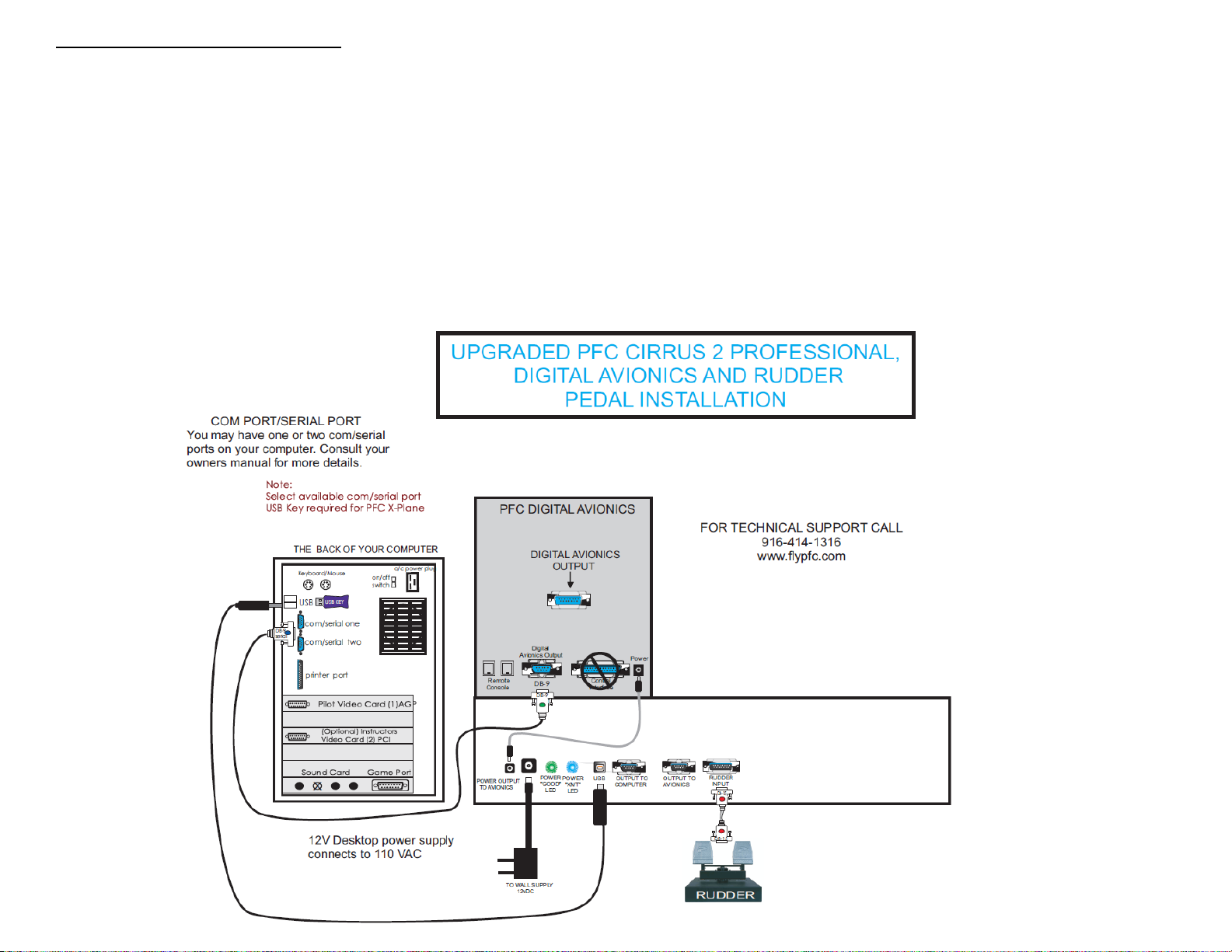
Enabling the Digital Avionics Panel
Diagram 1
The new USB HWC3 on the C2 Professional will require you to connect your avionics panel directly to the serial port. Please refer to the
Diagram 1 below.
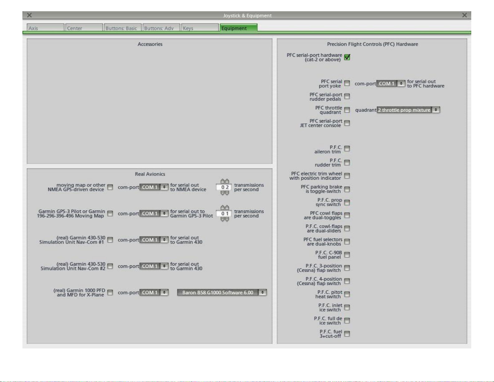
Once the avionics panel is connected as shown in the diagram you will need to enable the avionics in the X-plane software by:
1. Start X-Plane.
2. Go to the Settings.
3. Then choose Joystick & Equipment.
4. In the Joystick & Equipment page open the Equipment Tab.
5. In the Equipment tab, enable the check box for CAT 2 hardware of above. Make sure to uncheck the rest of the boxes. There
should only be one item that is checked.
Page 34
Page 35

Assigning the Cirrus 2 Professional power quadrant axes
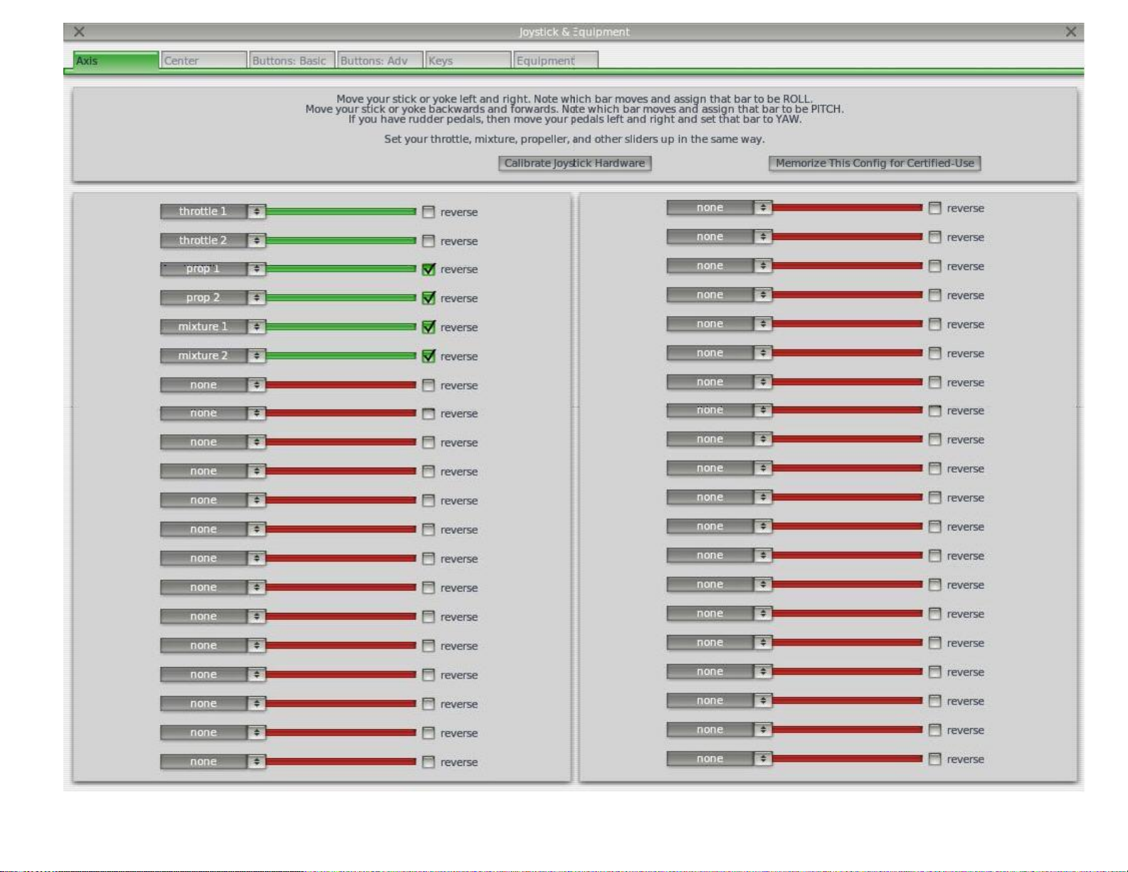
NOTE: The example shown below is for quadrant combination of 2-Throttle, 2-Prop RPM and 2- Mixtures. If the
lever combination you have is different, please make the necessary changes to the assignment.
1. Move the Left Throttle lever and you should see a green bar move from left to right.
2. Click on the drop down menu on the left of the moving bar and change it from none to Throttle1.
3. Move the Right Throttle lever and you should see a green bar move from left to right.
4. Click on the drop down menu on the left of the moving bar and change it from none to Throttle2.
5. Move the Left Prop lever and you should see a green bar move from left to right.
6. Click on the drop down menu on the left of the moving bar and change it from none to Prop 1.
7. Put a check on the reverse check box.
8. Move the Right Prop lever and you should see a green bar move from left to right.
9. Click on the drop down menu on the left of the moving bar and change it from none to Prop 2.
10. Put a check on the reverse check box.
11. Move the Left Mixture lever and you should see a green bar move from left to right.
12. Click on the drop down menu on the left of the moving bar and change it from none to Mixture 1.
13. Put a check on the reverse check box.
14. Move the Right Mixture lever and you should see a green bar move from left to right.
15. Click on the drop down menu on the left of the moving bar and change it from none to Mixture 2.
16. Put a check on the reverse check box.
Assigning the pedal axes
NOTE: You will need to calibrate your PFC Cirrus / Professional Rudder Pedals first before assigning the
function in X-plane. Please refer to the instructions that you have received with your pedals.
1. Start X-Plane.
2. Once running, look for Settings on the menu on the top of the screen.
3. From the settings menu, choose Joystick & Equipment.
4. Choose the Axis tab as shown below.
5. Apply Left brake and you should see a green bar move from left to right.
6. Click on the drop down menu on the left of the moving bar and change it from none to Left Toe
Brake.
7. Put a check on the reverse check box.
8. Apply Right brake and you should see a green bar move from left to right.
9. Click on the drop down menu on the left of the moving bar and change it from none to Right Toe
Brake.
10. Put a check on the reverse check box.
11. Move the Rudder axis and you should see a green bar move from left to right.
12. Click on the drop down menu on the left of the moving bar and change it from none to Yaw.
Page 36
REV:091130
 Loading...