

Page 1
P r e c i s i o n F l i g h t C o n t r o l s , I n c .
S e r i a l C A T I S y s t e m a n d X - P l a n 9 S e t u p G u i d e
Page 2

Preface
This setup guide will walk you through the necessary steps to setup your CAT I System with X-Plane 9.xx.
For connection diagram please refer to the packet that you received with the CAT I System.
CAT I System includes:
Cirrus Yoke
Throttle Quadrant Console
Avionics Panel with Remote Instrument Controller
Cirrus Rudder Pedals
This setup guide assumes that you have already installed the X-Plane 9.xx software. If you have not
installed the X-Plane 9.xx software, please install it now and refer to this guide once installation is done. For
reference on software installation, please refer to the software manual that you have received.
Getting the COM Port information:
The COM port or serial port is a port used by the CAT I System to communicate to X-Plane. It is
important to know the correct COM port number that your CAT I System is connected to, as this information will
be necessary for proper communication and operation between X-Plane and CAT I System. The steps below
will guide you to find out the correct com port number.
1. Is X-Plane running? If it is, please exit the X-Plane by moving your mouse to the top of the screen and
click on FILE and then QUIT.
2. Go to Start then choose Control Panel.
3. If you are seeing Pick a category, choose Performance & Maintenance then choose System. If not just
choose System.
4. From the Systems Window, choose Hardware then Device Manager
5. Expand the Ports list by clicking on the plus (+) sign
6. Make a note of the numbers on the Communications Port.
7. Close the Device Manager window, the System Window and the Control Panel Window.
Setting Up CAT I in X-Plane
8. Start X-Plane.
9. At this point you should see an aircraft at the end of a runway, if you do, move the mouse all the way to
the top and from the menu bar, choose Settings.
10. Choose Joystick & Equipment, then choose Equipment Tab
11. Enable the check boxes as shown in Figure 1.1
12. Once all the options pictured are enabled, Change the com port number to the one that you noted
from Step 6.
13. Now that you have selected correct com port, close the Equipment Window by clicking on the (x)
upper left hand corner.
14. Now move the mouse all the way to the top and from the menu bar choose File then choose Quit.
15. Once you are back in Windows Desktop start X-Plane again.
Serial CAT I and X-plane 9 Setup Guide 2 | P a g e
Page 3
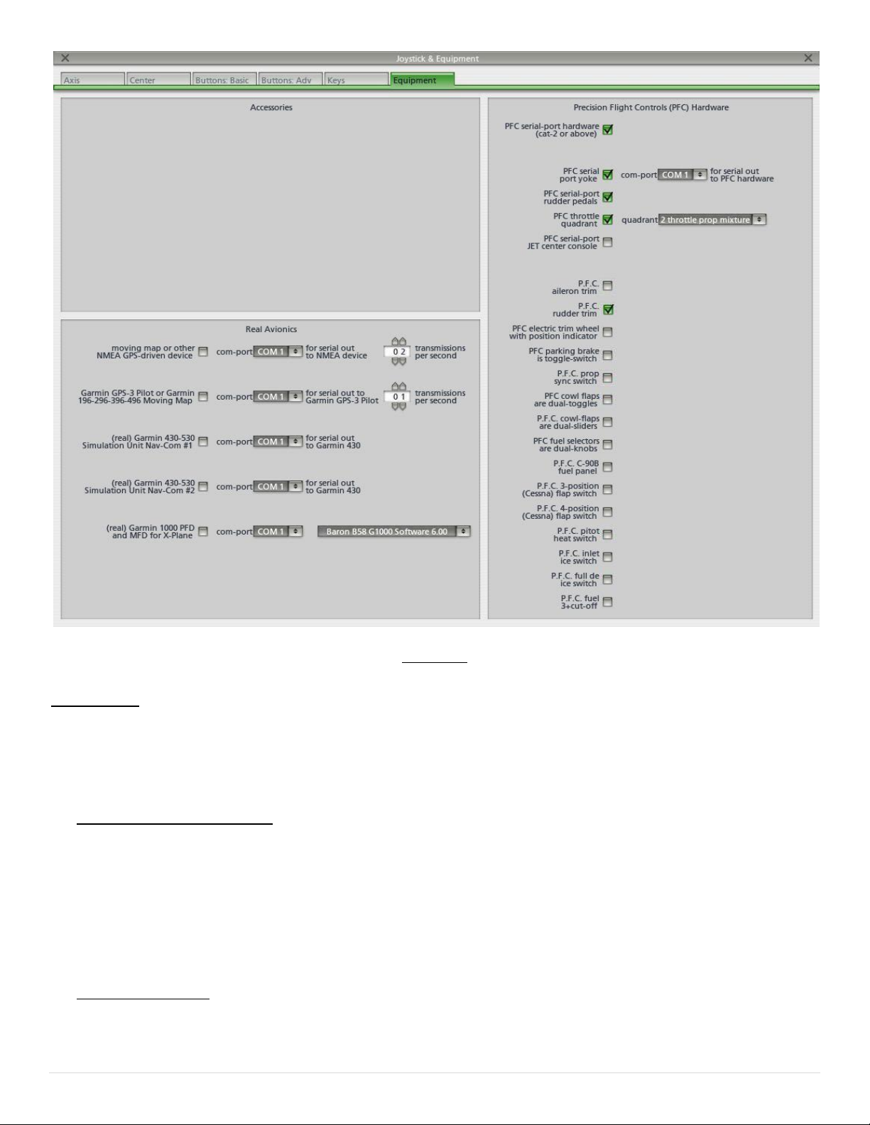
Figure 1.1
Calibration:
16. Start X-Plane
17. Now move the mouse all the way to the top and from the menu bar, choose Settings.
18. From the Settings, choose Joystick & Equipment, and then choose Center.
Power Quadrant Calibration:
19. Make sure a lever is installed on the console. A 6-lever or twin-prop is preferred for calibration
purposes, if you do not have one you can use what you have.
20. Push all the levers full forward.
21. Click on SET MAX on Throt1, Throt2, Throt3, Throt4, Throt5, and Throt6.
22. Pull the levers all the way to aft position or bottom
23. Click on SET MIN on Throt1, Throt2, Throt3, Throt4, Throt5, and Throt6.
Aileron Calibration:
24. Now turn and hold your yoke all the way to the LEFT and click on Set LEFT on ROLL
25. Now turn and hold your yoke all the way to the RIGHT and click on Set RIGHT on ROLL
26. Center the yoke now and click on SET CENTER on ROLL
Serial CAT I and X-plane 9 Setup Guide 3 | P a g e
Page 4

Elevator Calibration:
Serial_CAT1_X-Plane9_Setup_Guide.pdf REV: 051910
27. Pull the and hold yoke all the way out and click on SET UP on PITCH
28. Push and hold the yoke all the way in and click on SET DOWN on PITCH
29. Center the yoke now and click on SET CENTER on PITCH
Rudder Trim Calibration:
NOTE: To assure proper Rudder trim function, you will need to make sure that your trim is a separate
channel. To test, move your rudder trim while in Center tab and check if the rudder trim indicator (green
shade) moves. If it does not move, skip this and go back to Step 11 and disable the PFC Rudder Trim
check box.
30. Make sure the Rudder Trim is turned all the way to the left and click on SET LEFT on RUD TRIM
31. Make sure the Rudder Trim is turned all the way to the Right and click on SET RIGHT on RUD TRIM
32. Now make sure that the Rudder Trim is Centered and click on Set Center on RUD TRIM
If you do not have Precision Flight Controls Cirrus Pedals please skip this step. Please also go back to Step 13
and Disable the PFC Serial Port Rudder Pedals.
33. Push the Right Pedal all the way to the Right and click on SET RIGHT on the RUDDER
34. Push the LEFT Pedal all the way to the Left and click on SET LEFT on the RUDDER
35. Center the PEDALS now and click on SET CENTER on RUDDER
36. We’re almost done, step on both of your brakes at the same time and click on SET MAX on the LEFT
BRAKE and RIGHT BRAKE
37. Release the brakes and click on SET MIN
38. Click on X on the upper left hand corner.
39. Now move your mouse to the top of the screen and click on FILE and then QUIT
40. Start X-Plane again and all the controls should work now.
Serial CAT I and X-plane 9 Setup Guide 4 | P a g e
 Loading...