

Page 1

S E R I A L M o d u l a r F l i g h t D e c k
w i t h G N S 4 3 0 and
X - P l a n e 9 S e t u p G u i d e
Set Up Guide For MFD with G430 and X-Plane 9 Page 1
Page 2

Preface
This setup guide will walk you through the necessary steps to setup your Serial MFD with
Gamin 430 with X-Plane 9.XX. For connection diagram please refer to the packet that you
received with the console.
This setup guide assumes that you have already installed the X-Plane 9.XX software. If
you have not installed the X-Plane 9.XX, please install it now and refer to this guide once
installation is done. For reference on software installation, please refer to the software manual
that you have received.
Terminology
Master PC: Refers to the computer that runs the instrument and instructor’s station.
Visual PC: Refers to the computer that runs the outside view only.
NOTE: Make sure that you are controlling the correct PC prior to making any
changes. Failure to do so will result in X-Plane not operating properly.
Configuration Phases
Section 1: Configure the Master PC
A. Configure Windows Screen Resolution page on Master PC.
B. Enable PFC Hardware options for MFD
C. Calibrate PFC Hardware
D. Configure Rendering Options page for Master PC.
E. Enable the Instructor’s Station.
F. Enable communication from Master PC to Visual PC.
G. Enabling communication to Visual PC
Section 2: Configure the Visual PC
H. Configure Rendering Options page for Visual Computer.
I. Enabling communication to Master Computer from Visual Computer.
Set Up Guide For MFD with G430 and X-Plane 9 Page 2
Page 3

Table of Contents
Section 1: Configuration of the Master PC ........................................................................................... 4
A. Configure Windows Screen Resolution page on Master PC ............................................... 4
Enable both screens in Windows ........................................................................................ 4
B. Enable PFC hardware options in X-Plane 9 ............................................................................ 7
Getting the Com Port information ...................................................................................... 7
Enable PFC hardware options ............................................................................................. 7
Enable the Garmin GPS ........................................................................................................ 9
C. Calibrate PFC Hardware......................................................................................................... 10
Power Quadrant Calibration: ............................................................................................ 10
Aileron Calibration: ............................................................................................................. 10
Elevator Calibration: ........................................................................................................... 10
Check for discrete Aileron and Rudder trim Input: ........................................................ 10
Trim calibration .................................................................................................................... 10
Rudder Pedals Calibration ................................................................................................. 11
D. Configure Rendering Options page for Master PC. ........................................................... 12
E. Enable the Instructor’s Station................................................................................................ 13
F. Enable communication from Master PC to Visual PC. ....................................................... 13
Changing the IP Address of the Master Machine .......................................................... 13
Enable communication from Master PC to Visual PC in X-Plane 9 .............................. 16
Section 2: Configure Visual PC ............................................................................................................. 17
G. Configure Rendering Options Page for Visual PC............................................................... 17
H. Enabling communication to Visual PC from Master PC ..................................................... 18
Changing the IP Address of the Visual PC ....................................................................... 18
Enable communication to Master PC in X-Plane 9 ........................................................ 21
I. Master Rendering Option Setting Full Size ............................................................................ 22
J. Visual Rendering Option Full Size ........................................................................................... 23
Set Up Guide For MFD with G430 and X-Plane 9 Page 3
Page 4
Section 1: Configuration of the Master PC
A. Configure Windows Screen Resolution page on Master PC
Enable both screens in Windows
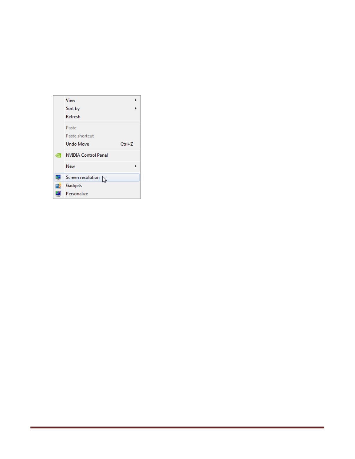
1. Right click in the desktop screen where there are no icons and choose Screen
Resolution.
2. Click on identify.
3. You should see a white number “1” on the instructor monitor. If not follow the
instructions below:
a. Click on Cancel.
b. Shutdown the computer.
c. On the back of the Master PC switch the video port that the video cables are
connected.
d. Turn on the computer.
e. Start form step 1 and do the same test.
f. It is important that #1 display is on the instructor’s monitor.
Set Up Guide For MFD with G430 and X-Plane 9 Page 4
Page 5
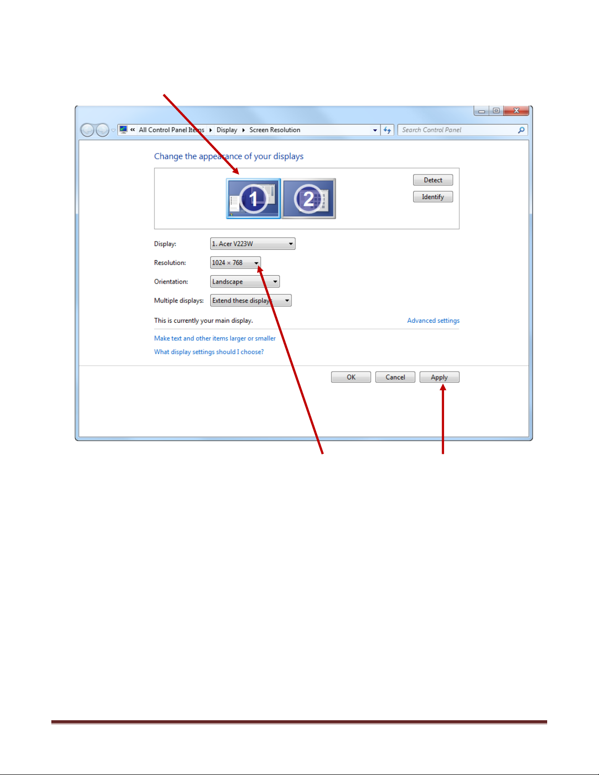
4. Once #1 display is on the Instructor’s monitor
5. Select the #1 display with a single left click and it will be highlighted by a blue box.
6. Make sure that #1 display is on the left and #2 display on the right.
7. Once selected change the resolution to 1024 X 768, then click on apply.
Set Up Guide For MFD with G430 and X-Plane 9 Page 5
Page 6
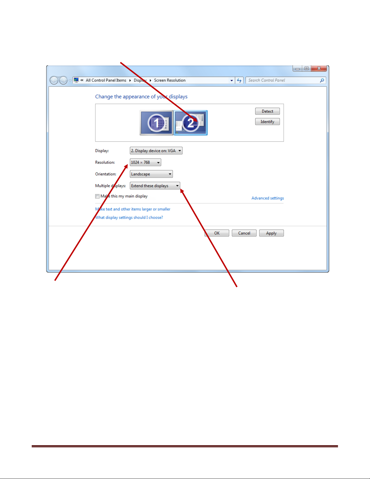
8. Select the #2 display with single click. It should have a blue square highlight as shown
below.
9. After selecting the #2, set the Resolution to 1024 X 768.
10. Next is to change the option for Multiple Displays to Extend these displays.
11. Click on Apply to accept the changes and click on OK close the window.
12. Once you are done with steps 1 to 8, your Screen Resolution window should look just
like in the picture above. Special attention should be given to the arrangement of #1
and #2 display, #1 on the left and #2 on the right. Also the displays should be aligned
and even as shown.
Set Up Guide For MFD with G430 and X-Plane 9 Page 6
Page 7

B. Enable PFC hardware options in X-Plane 9
Getting the Com Port information
The Com Port is a 9 pin port used by MFD and Garmin 430 (G430) to communicate to X-
Plane. Your system will use 2 com ports, one for the MFD and the other for the G430.
It is important to know the correct COM port number that the MFD and G430 is
connected to as this information will be necessary for proper communication to X-Plane.
The steps below will guide you to find out the correct com port number.
1. If X-Plane running, exit out by moving your mouse to the top of the screen and click on
FILE and then QUIT.
2. Go to Start then choose Control Panel.
3. From control panel choose System.
4. From the System window choose Device Manager.
5. Expand the Ports list by clicking on the plus (>) sign.
6. Make a note of the numbers on the Communications Port.
7. Close the Device Manager window, the System Window and the Control Panel
Window.
Enable PFC hardware options
8. Start X-Plane.
9. If a warning box comes up saying “PFC Hardware is not found; do not use sim for flight
training” or “Frame rate check passed, PFC hardware found, Flight Training is
Approved”, press the Enter key.
10. At this point you should see an aircraft at the end of a runway, if you do, move the
mouse all the way to the top and from the menu bar, choose Settings.
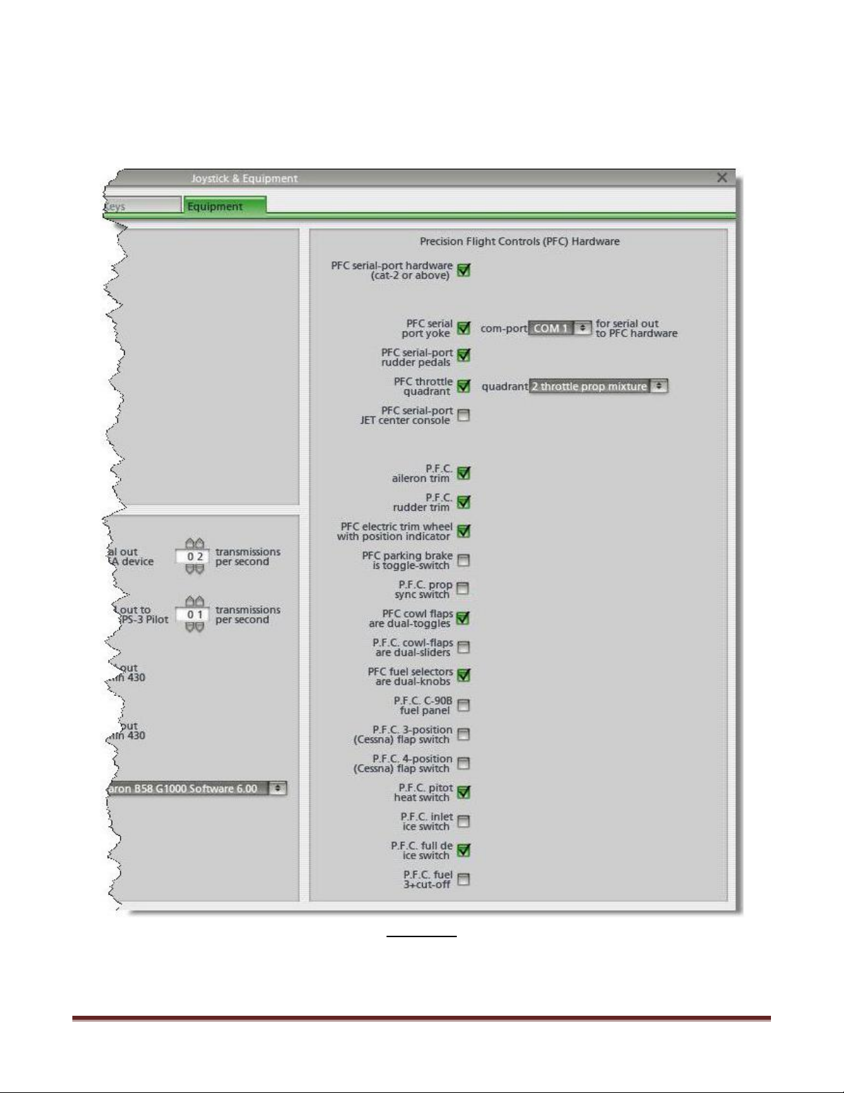
11. Choose Joystick, Keys & Equipment, then choose Equipment Tab
12. Enable the check boxes as shown in Figure 1.1
NOTE: If the warning box in step 9 says “Frame rate check passed, PFC hardware
found, Flight Training is approved” proceed to step 14 and skip step 13.
13. Once all the options pictured are enabled, change the com port number of the “COM
PORT for SERIAL OUT TO PFC HARDWARE” to the one that you noted from Step 6.
14. Now that you have selected correct com port, close the Equipment Window by
clicking on the (x) upper left hand corner.
15. Now move the mouse all the way to the top and from the menu bar choose File then
choose Quit.
16. Once you are back in Windows Desktop start X-Plane again.
Set Up Guide For MFD with G430 and X-Plane 9 Page 7
Page 8
17. If after restarting X-Plane you still get the error “PFC Hardware is not found; do not use
sim for flight training” go back to Step 13 and change the COM port number again until
you get “FRAME RATE CHECK PASSED,PFC HARDWARE FOUND, FLIGHT TRAINING IS
APPROVED.” Once this message appears go to Step 18.
Figure 1.1
Set Up Guide For MFD with G430 and X-Plane 9 Page 8
Page 9
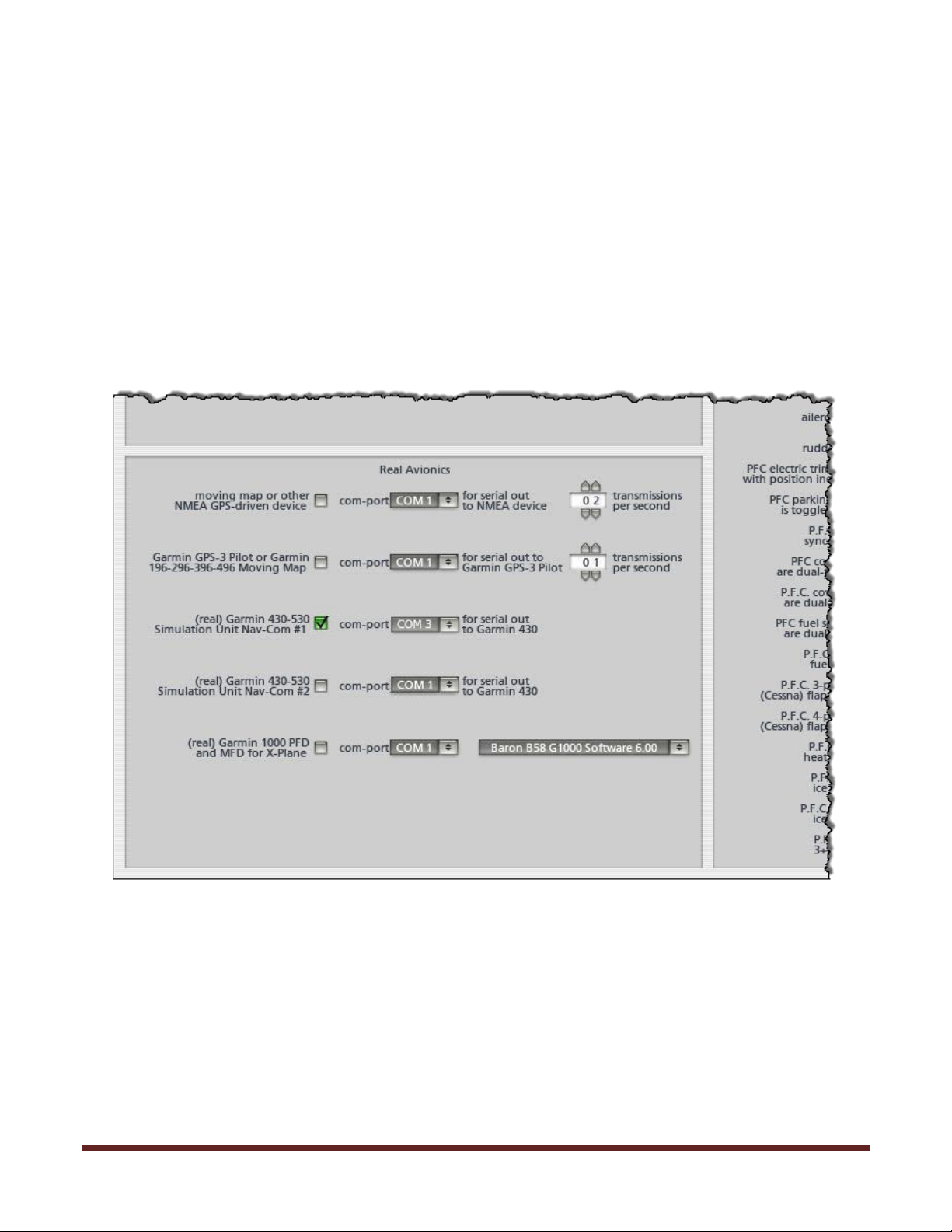
Enable the Garmin GPS
18. Look back in step 6 and gather the com port information. One of the two com port
numbers has been assigned to your MFD. The second one will be assigned to the
Garmin GPS. Note that number here: _____
19. Start X-Plane 9
20. The warning box will come up stating “Frame rate check passed, PFC hardware found,
Flight Training is Approved”
21. Press the enter key.
22. Click on X on the upper left hand corner
23. Move your mouse to top of the screen and choose settings.
24. From the settings menu choose Joystick, Keys & Equipment.
25. In the window, go to the Equipment tab.
26. In the equipment tab, enable the check box for (real) Garmin 430-530 Simulation Unit
Nav-Com#1
27. Change the com-port number to the one you noted on step 18.
28. Click on X on the upper left corner to close the equipment window.
29. Click on X on the upper left corner to close the instructor station window.
30. Move your mouse to the top of the screen and from the menu choose File and the Quit.
Set Up Guide For MFD with G430 and X-Plane 9 Page 9
Page 10

C. Calibrate PFC Hardware
1. Start X-Plane
2. A the advisory stating “Frame rate check passed, PFC hardware found, Flight Training is
Approved”
3. Press the enter key.
4. Now move the mouse all the way to the top and from the menu bar, choose Settings.
5. From the Settings, choose Joystick & Equipment, and then choose Center.
Power Quadrant Calibration:
6. Make sure that you have a 6-lever or twin-prop lever installed to the console. Once
installed, push all levers to full forward position.
7. Click on SET MAX on Throt1, Throt2, Throt3, Throt4, Throt5, and Throt6.
8. Pull the levers all the way to aft position or bottom.
9. Click on SET MIN on Throt1, Throt2, Throt3, Throt4, Throt5, and Throt6.
Aileron Calibration:
10. Now turn and hold your yoke all the way to the LEFT and click on Set LEFT on ROLL.
11. Now turn and hold your yoke all the way to the RIGHT and click on Set RIGHT on ROLL.
12. Center the yoke now and click on SET CENTER on ROLL.
Elevator Calibration:
13. Pull and hold yoke all the way out and click on SET UP on PITCH.
14. Push and hold the yoke all the way in and click on SET DOWN on PITCH.
15. Center the yoke now and click on SET CENTER on PITCH.
Check for discrete Aileron and Rudder trim Input:
Prior to calibrating the trim, you will need to check if the Aileron and Rudder Trim are
discrete trim channels.
To test, turn the Aileron and Rudder Trim several times and if green shade on the column for
AIL TRM and RUD TRM reflects your input, you will proceed with calibration.
Otherwise, you will go back to 8 and disable the check box for PFC Aileron Trim and PFC
Rudder Trim. If only RUD TRM works, then you will only disable the PFC Aileron Trim.
Trim calibration
16. Make sure the Aileron Trim is turned all the way to the left and click on SET LEFT on AIL
TRIM.
17. Make sure the Aileron Trim is turned all the way to the Right and click on SET RIGHT on
AIL TRIM.
18. Now make sure that the Aileron Trim is Centered and click on Set Center.
19. Make sure the Rudder Trim is turned all the way to the left and click on SET LEFT on RUD
TRIM.
20. Make sure the Rudder Trim is turned all the way to the Right and click on SET RIGHT on
RUD TRIM.
21. Now make sure that the Rudder Trim is Centered and click on Set Center on RUD TRIM.
Set Up Guide For MFD with G430 and X-Plane 9 Page 10
Page 11

Rudder Pedals Calibration
22. Push the Right Pedal all the way to the Right and click on SET RIGHT on the RUDDER
23. Push the LEFT Pedal all the way to the Left and click on SET LEFT on the RUDDER
24. Center the PEDALS now and click on SET CENTER on RUDDER
25. We’re almost done, step on both of your brakes at the same time and click on SET MAX
on the LEFT BRAKE and RIGHT BRAKE
26. Release both brakes and click on SET MIN on the LEFT BRAKE and RIGHT BRAKE
27. Click on X on the upper left hand corner.
28. Now move your mouse to the top of the screen and click on FILE and then QUIT.
Set Up Guide For MFD with G430 and X-Plane 9 Page 11
Page 12
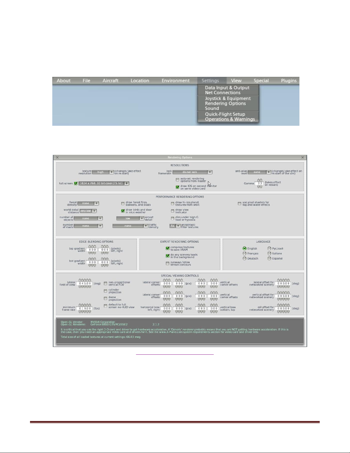
D. Configure Rendering Options page for Master PC.
13. Start X-Plane.
14. Acknowledge the advisory by clicking on Understood
15. Move your mouse to the top of the screen and choose Settings from toolbar.
16. From the settings menu choose Rendering Options.
17. In the rendering option page, set the parameters as shown.
(view full size on page 22)
18. Once done, click on X.
Set Up Guide For MFD with G430 and X-Plane 9 Page 12
Page 13
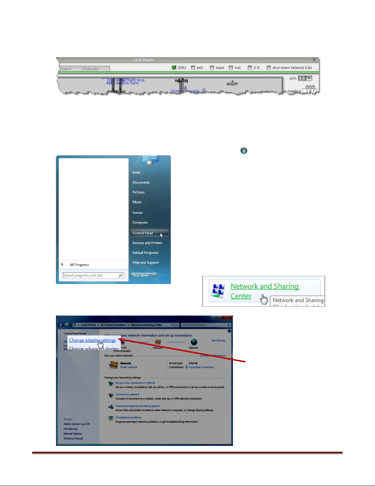
E. Enable the Instructor’s Station
19. In the Local Region window, enable the IOS check box as shown below.
20. Once back to the instructor’s station, click on Quit All.
F. Enable communication from Master PC to Visual PC.
Changing the IP Address of the Master Machine
21. Open Network Connections by clicking the Start button, click on the Control Panel
22. Clicking Network and Sharing Center.
23. Click on the Change
Adapter Settings on the left
menu.
Set Up Guide For MFD with G430 and X-Plane 9 Page 13
Page 14
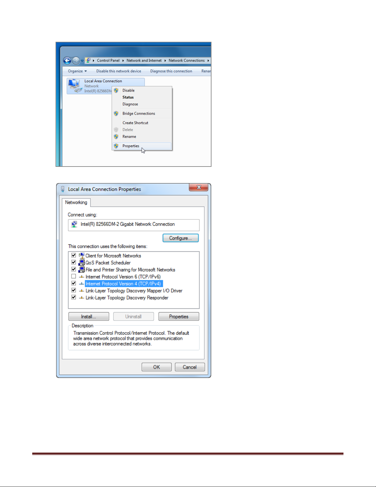
24. Right-click the Local Area connection and then click Properties.
25. Open the TCP/IPv4 with a double left click.
Set Up Guide For MFD with G430 and X-Plane 9 Page 14
Page 15
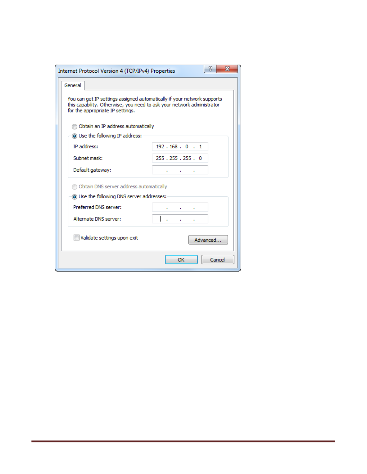
26. In the TCP/IPv4 Properties, click on specify an IP address, click Use the following IP
address, and then, in the IP address, Subnet mask, and Default gateway boxes, type
the IP address of 192.168.0.1 and the Subnet Mask of 255.255.255.0.
27. Click on OK.
28. Close any window that is open at this time.
Set Up Guide For MFD with G430 and X-Plane 9 Page 15
Page 16
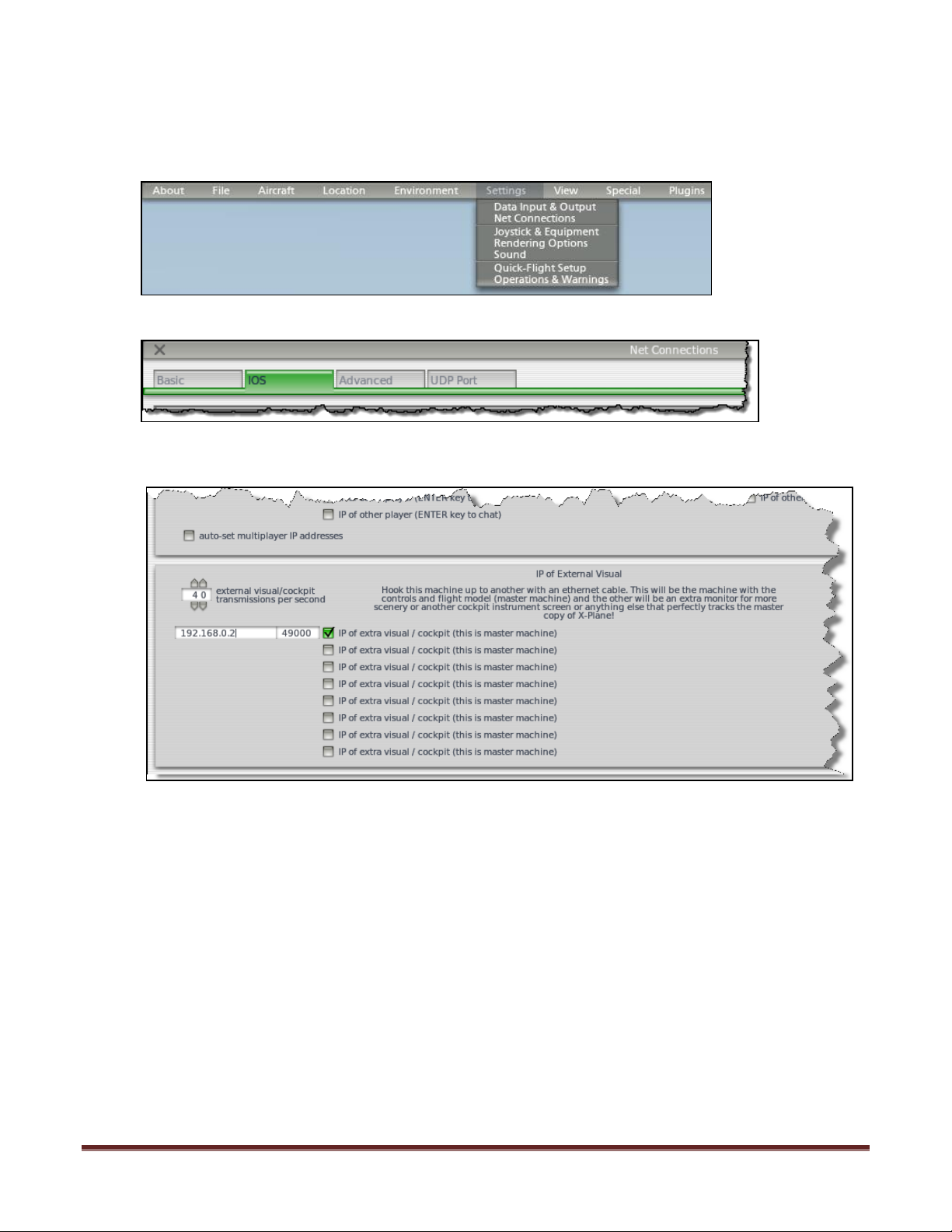
Enable communication from Master PC to Visual PC in X-Plane 9
29. Start X-Plane 9
30. Close the instructor’s station by clicking X on the upper left hand corner.
31. Go into Settings>Net Connections
32. The Net Connections go to the INET1 or Basic Tab.
33. Enable the box as shown and input the numbers 192.168.0.2 on the left hand box and
49000 on the right hand box.
34. Once you have enabled the check box and input the numbers as shown in the boxes,
proceed to other tabs and uncheck any other boxes that are not use.
35. Once you have made sure that the only one that checked is the item as shown above
close the window and exit X-Plane to save the changes that you have made.
Set Up Guide For MFD with G430 and X-Plane 9 Page 16
Page 17
Section 2: Configure Visual PC
G. Configure Rendering Options Page for Visual PC
1. Start X-Plane.
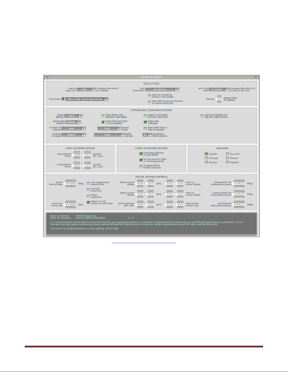
2. Move your mouse to the top of the screen and choose Settings from toolbar.
3. From the settings menu choose Rendering Options.
4. In the rendering option page, set the parameters as shown.
(view full size on page 22)
Set Up Guide For MFD with G430 and X-Plane 9 Page 17
Page 18
H. Enabling communication to Visual PC from Master PC
Changing the IP Address of the Visual PC
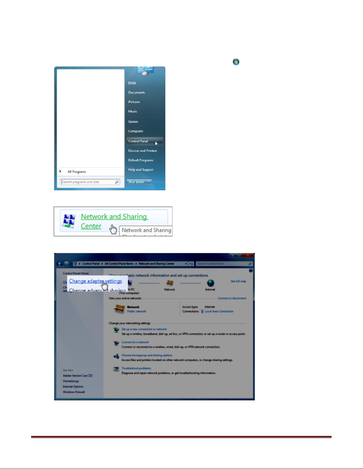
5. Open Network Connections by clicking the Start button, click on the Control Panel
6. Clicking Network and Sharing Center.
7. Click on the Change Adapter Settings on the right menu.
Set Up Guide For MFD with G430 and X-Plane 9 Page 18
Page 19
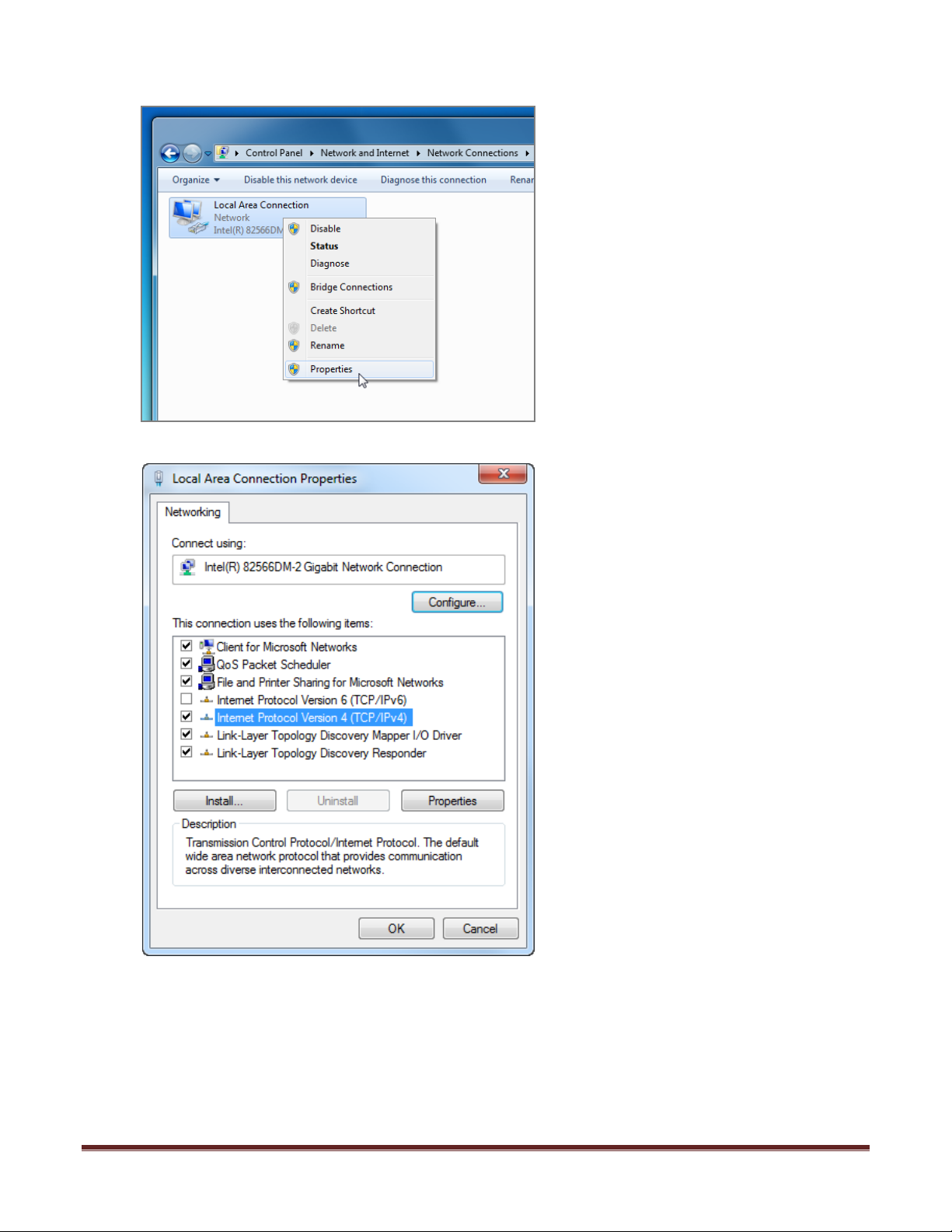
8. Right-click the Local Area connection and then click Properties.
9. Open the TCP/IPv4 with a double left click.
Set Up Guide For MFD with G430 and X-Plane 9 Page 19
Page 20
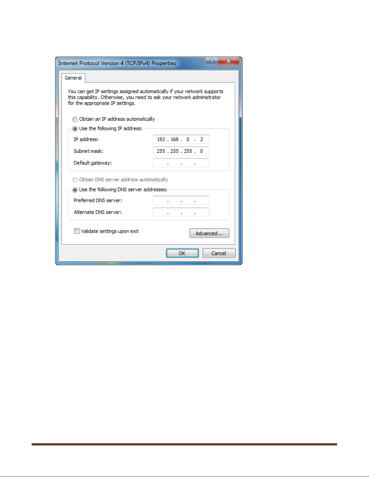
10. In the TCP/IPv4 Properties, click on specify an IP address, click Use the following IP
address, and then, in the IP address, Subnet mask, and Default gateway boxes, type
the IP address of 192.168.0.2 and the Subnet Mask of 255.255.255.0.
11. Click on OK.
12. Close any window that is open at this time.
Set Up Guide For MFD with G430 and X-Plane 9 Page 20
Page 21
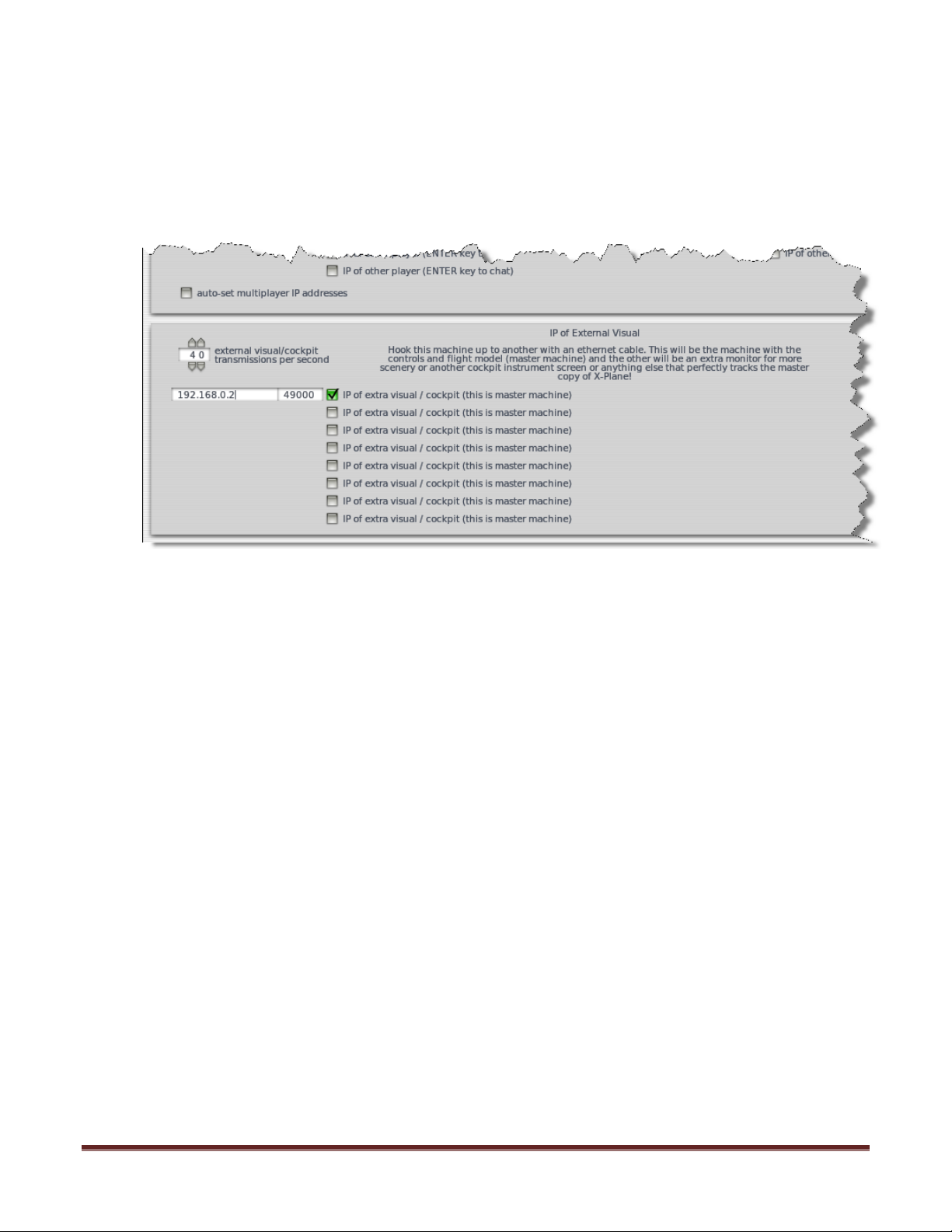
Enable communication to Master PC in X-Plane 9
13. Start X-Plane 9 on Master machine, this is the PC that is running instrument and IOS
14. Once X-Plane 9 has started, close the instructor’s station by clicking X on the upper left
hand corner.
15. Go into Settings>Net Connections
16. In the Data Input / Output page, go to the INET2 tab.
17. Enable the box as shown:
18. Once you have enabled the check box and input the numbers as shown in the boxes
close the window and exit X-Plane.
Set Up Guide For MFD with G430 and X-Plane 9 Page 21
Page 22
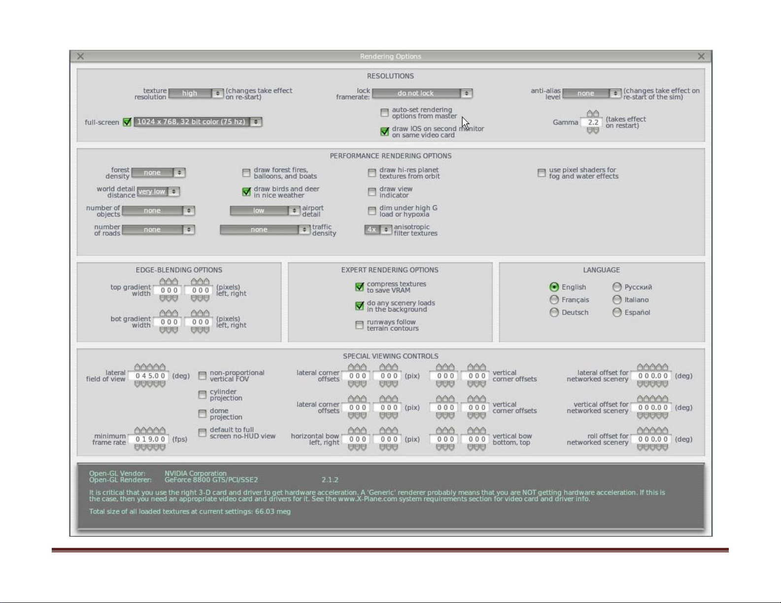
I. Master Rendering Option Setting Full Size
Master PC Rendering Options Settings
Set Up Guide For MFD with G430 and X-Plane 9 Page 22
Page 23
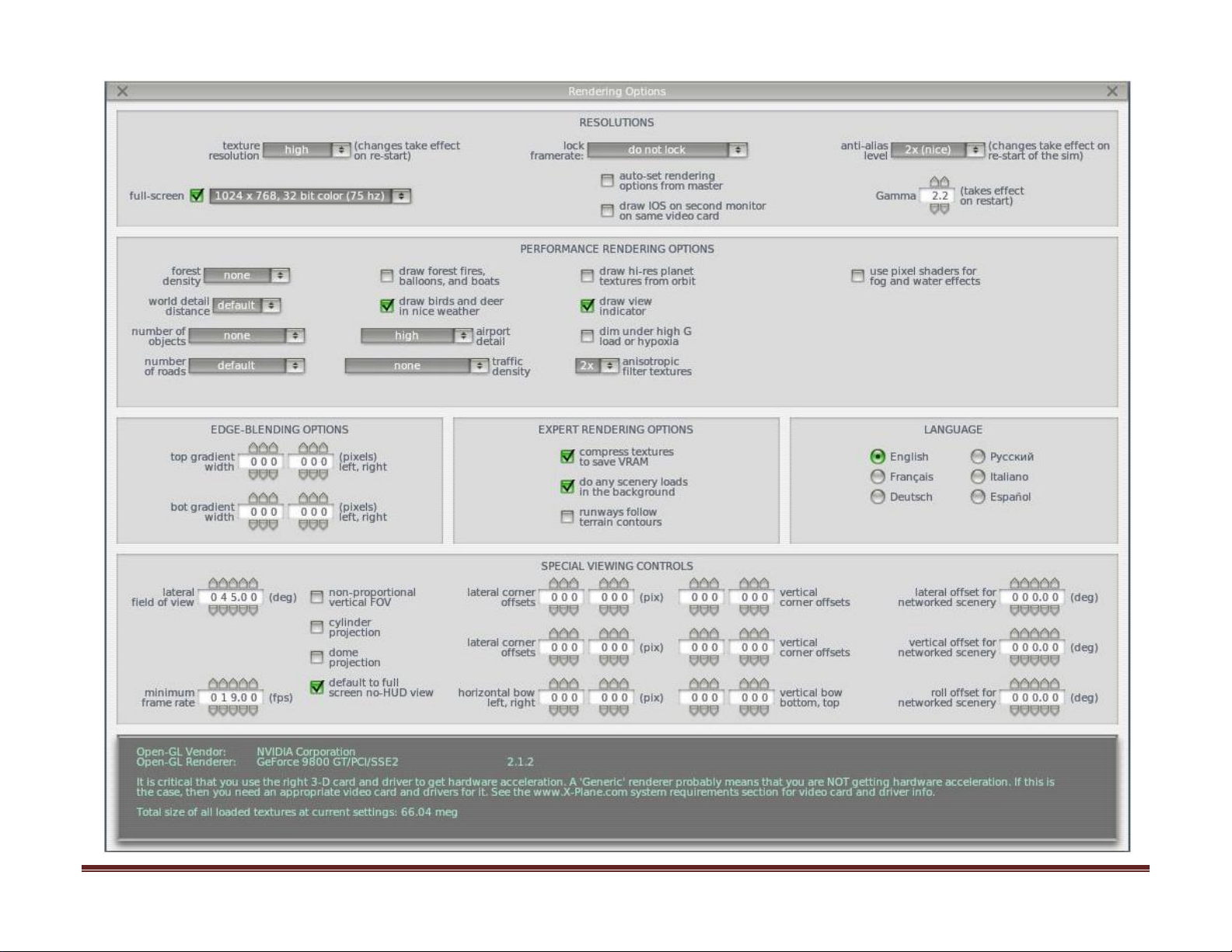
J. Visual Rendering Option Full Size
Visual Rendering Options Settings
Set Up Guide For MFD with G430 and X-Plane 9 Page 23
 Loading...