

Page 1

PDW30 Point-to-Point Wireless Bridge
Instruction Manual
Wireless System
• Signal Wire Replacement in a Rugged, Industrial Housing
• Simple to Order, Configure, & Install
• Range: 1 Mile Line-of-Sight, 500 ft. Indoor
• Analog & Digital Inputs and Outputs, RS-485 Communications
• Remote or Attached Antenna
• Repeaters and Directional Antennas Available
• Flanges for Wall or Pipe Mounting
• PC Software Available for Even Easier Setup
• Rugged, NEMA 4X/IP68 Enclosure
PRECISION DIGITAL CORPORATION
www. .com
[email protected]1.800.561.8187
Page 2
PDW30 Point-to-Point Wireless Bridge Instruction Manual
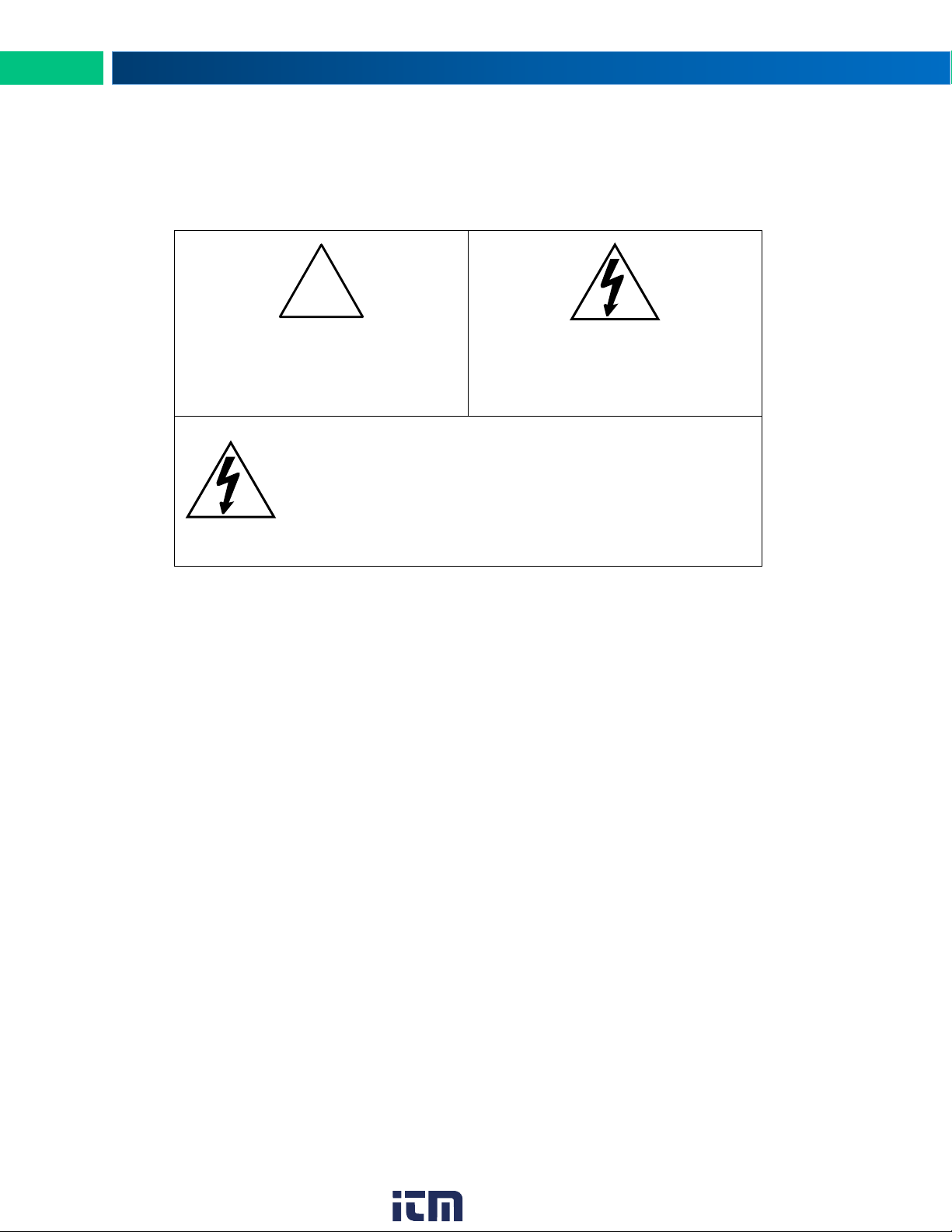
Caution: Read complete instruc-
tions prior to installation and opera-
tion of the device.
Warning: Risk of electric shock or
personal injury.
Warning!
This product is not recommended for life support applications or applications where malfunctioning could result in personal injury or property loss. Anyone using
this product for such applications does so at their own
risk. Precision Digital Corporation shall not be held liable for damages resulting from such improper use.
!
Disclaimer
The information contained in this document is subject to change without notice. Precision
Digital makes no representations or warranties with respect to the contents hereof and specifically disclaims any implied warranties of merchantability or fitness for a particular purpose.
Limited Warranty
Precision Digital Corporation warrants this product against defects in material or workmanship for the specified period under “Specifications” from the date of shipment from the factory. Precision Digital’s liability under this limited warranty shall not exceed the purchase
value, repair, or replacement of the defective unit.
Registered Trademarks
Modbus® is a registered trademark of Schneider Electric. All other trademarks mentioned in
this document are the property of their respective owners.
© 2017 Precision Digital Corporation. All rights reserved.
2
www. .com
[email protected]1.800.561.8187
Page 3

PDW30 Point-to-Point Wireless Bridge Instruction Manual
Table of Contents
Table of Contents .................................................... 3
Table of Figures ...................................................... 3
Introduction ............................................................. 4
Ordering Information ............................................... 4
Specifications .......................................................... 5
General ................................................................ 5
Isolated 4-20 mA Transmitter Output .................. 5
Digital Input / Output Terminal ............................. 5
RS-485 Modbus® RTU Serial Comms ................. 6
PDW Manager Software ...................................... 6
Safety Information ................................................... 6
Installation ............................................................... 6
Unpacking ............................................................ 6
Pre-Installed Conduit Plug ................................... 7
Mounting Instructions .......................................... 7
Cover Jam Screw ................................................ 7
FCC Notice .......................................................... 7
IMPORTANT .................................................... 7
Canada (IC) Notice .......................................... 7
Connections ......................................................... 8
Power Connector ............................................. 9
Signal Connector ........................................... 10
4-20 mA Output Connector ............................ 10
Digital I/O Connector ..................................... 11
Modbus RTU Serial Communications............ 11
Setup and Programming ....................................... 12
Overview ............................................................ 12
Programming Buttons ........................................ 13
Quick Tip ........................................................... 13
PDW Manager Software .................................... 14
Display Functions & Messages ......................... 15
Primary Unit ................................................... 15
Secondary Unit .............................................. 16
Setup Menu ....................................................... 17
Entering Numeric Values ............................... 17
Primary Device Menus ................................... 18
Secondary Device Menus .............................. 21
Display Signal I/O and Digital I/O Status ....... 21
Programming with PDW Manager ..................... 22
Troubleshooting .................................................... 25
Factory Defaults & User Settings ...................... 28
Mounting Dimensions............................................ 29
PDA6963 Stainless Steel Pipe Mounting Kit ........ 29
Table of Figures
Figure 1. PDW30 Device Assembly, Rear View ........................................................................................... 8
Figure 2. Power Connections ........................................................................................................................ 9
Figure 3. PDW30 and 2-Wire Transmitter Powered from Same Supply ...................................................... 9
Figure 4. Analog Input Connections ........................................................................................................... 10
Figure 5. 4-20 mA Output Connections ..................................................................................................... 10
Figure 6. Digital I/O Connections ................................................................................................................ 11
Figure 7. Three- and Five-Wire RS-485 Modbus Connections ................................................................... 11
Figure 8. Multiple Device RS-485 Modbus Connection .............................................................................. 11
Figure 9. Enclosure Dimensions – Front View ............................................................................................ 29
Figure 10. Enclosure Dimensions – Side Cross Section View ................................................................... 29
Figure 11. PDA6963 Stainless Steel Pipe Mounting Kit ............................................................................ 29
3
www. .com
[email protected]1.800.561.8187
Page 4

PDW30 Point-to-Point Wireless Bridge Instruction Manual
Model
Description
PDW30-SNA
PDW30 Point-to-Point Wireless Bridge
Model
Description
PDA10
PDW Wireless Signal Strength Survey Tool
PDA3120-N
RP-SMA F to N Male Antenna Cable 20ft
PDA3140-N
RP-SMA F to N Male Antenna Cable 40ft
PDA3120-S
RP-SMA M/F Antenna Cable 20ft
PDA3140-S
RP-SMA M/F Antenna Cable 40ft
PDA3900-12-N
PDW 900 MHz Antenna, 1/2" NPT
PDA3900-34-N
PDW 900 MHz Antenna, 3/4" NPT
PDA3900-6Y-N
Yagi Antenna 6dB
PDA3900-9Y-N
Yagi Antenna 9dB
PDA6963
Stainless Steel PDW30 Mounting Kit
PDA-MICROUSB
Micro-USB PC Programming Cable (Included)
PDW30-RNA
PDW30 Repeater Kit
Introduction
The Precision Digital PDW30 gives you a simple, straightforward way to get an analog, discrete,
or Modbus® signal from where you have it to where you need it. It’s a point-to-point wireless
bridge packaged in a rugged, weather tight housing designed to meet the demands of industrial
installations.
The PDW30 is simple to order, simple to configure, and easy to trust with your application.
Guaranteed ranges assure it will work with your application, or you can send it back - no questions asked. A wireless survey tool is available for those who may require a site survey for
longer distances, making it easy to verify the installation will work the first time.
The PDW30 takes an analog, discrete, or Modbus® input and wirelessly broadcasts it to a second PDW30 unit. The secondary unit then recreates that signal at its location. The secondary
unit may also transmit its own analog, discrete, or Modbus signals back to the primary unit. Just
put the units in the field anywhere you have a signal and power.
A wide range of accessories, including mounting kits, antenna-related accessories, and repeaters, are available. The antenna may be directly attached or remotely located. High gain directional antennas are also offered.
Ordering Information
Standard Model
Accessories
4
www. .com
[email protected]1.800.561.8187
Page 5

PDW30 Point-to-Point Wireless Bridge Instruction Manual
Display
32-character dual-line alphanumeric
dot matrix LCD display with backlight (4.68mm x 2.21mm characters)
Display
Orientation
Display may be mounted at 180°
from default orientation
Network ID
Field selectable: 0 - 99
Programming
Methods
Four programming buttons (behind
glass) or PC with PDW Manager software.
Recalibration
All inputs and outputs are calibrated
at the factory. Recalibration is recommended at least every
12 months.
Process/
Digital I/O
Display
Press the display button once to
display the present analog input and
output. Press the display button
again to display digital I/O states.
Password
A programmable password restricts
modification of program settings.
Power
12-28 VDC, 5 W max
Non-Volatile
Memory
All programmed settings are stored
in non-volatile memory for a minimum of ten years if power is lost.
Isolation
500 V
Environmental
Operating temp. range: -40 to 65°C
(display inoperable < -20 °C)
Storage temp. range: -40 to 85°C
Relative humidity: 0 to 90% noncondensing
Connections
Removable screw terminal blocks
accept 16 to 30 AWG wire.
Enclosure
Cast aluminum with glass window,
0.3% max copper content, corrosion
resistant powder coating, color:
blue. NEMA 4X/IP68. Three ½" NPT
threaded conduit openings. One ½"
NPT stainless steel conduit plug
with 10 mm hex key fitting installed.
Mounting
May be mounted directly to conduit.
Two mounting holes for 1.5" pipe or
wall mounting. See Mounting Dimensions on page 29 for mounting
space requirements.
Signal Connector Tightening Torque
2.5 lb-in (0.28 Nm)
Shipping
Dimensions
17" x 14" x 9" (43.2 cm x 35.6 cm x
22.9 cm) (L x W X H)
Shipping
Weight
5 lbs. (2.27 kg)
Warranty
3 years parts & labor
Inputs
Field selectable: 4-20 mA, 0-10 V,
0-5 V, 1-5 V
Accuracy
±0.03% of calibrated span ±1 count
Temperature
Drift
0.005% of calibrated span/C max
from 0 to 65C ambient, 0.01% of
calibrated span/C max from -40 to
0C ambient
Input
Impedance
Voltage ranges: greater than
110 k;
Current ranges: less than 220
Signal Loss
Inputs will remain off (open circuit)
until wireless units are reconnected.
HART
Transparency
Analog input will not interfere with
existing HART communications on
the wired 4-20 mA signal
Output Source
Analog input from connected wireless unit
Calibration
Factory calibrated:
4.000 to 20.000 = 4-20 mA output
Accuracy
± 0.1% of span ± 0.004 mA
Loop Power
Supply
Internally powered; no external supply needed
Temperature
Drift
0.4 µA/C max from 0 to 65C ambient, 0.8 µA/C max from -40 to 0C
ambient
Signal Loss
mA output will become 3.2 mA after
approx. 25 seconds
Output Loop
Resistance
Power supply
Minimum
Maximum
24 VDC
10-ohms
900-ohms
Channels
Four (4) digital connections, independently field selectable as either
inputs or outputs
DI Logic High
3 to 5 VDC
DI Logic Low
0 to 1.1 VDC
DI Contact
Dry contact to ground can be used
to activate the input
DO Logic High
3 to 5 VDC
DO Logic Low
0 to 0.4 VDC
Source
Current
10 mA maximum output current
Sink Current
1.5 mA minimum input current
Signal Loss
Digital output goes to logic high
Specifications
Except where noted all specifications apply to operation at +25°C.
General
Analog Input
Isolated 4-20 mA Transmitter Output
Digital Input / Output Terminal
www. .com
5
[email protected]1.800.561.8187
Page 6
PDW30 Point-to-Point Wireless Bridge Instruction Manual
Frequency
900 MHz
Range
500 ft (152.4 m) indoor, 1 mi
(1.61 km) outdoor (line-of-sight)
Encryption
AES 128-bit encryption available
using PDW Manager software
Interference
Reduction
Frequency Hopping Spread Spectrum (FHSS)
Power Output
24 dBm (250 mW)
Sensitivity
-101 dBm
Compatibility
EIA-485
Connectors
Removable screw terminal connector
Max Distance
3,937' (1,200 m) max
Baud Rate
1200 – 57,600 bps
Data
8 bit (1 start bit, 2 stop bits)
Parity
Even, Odd, or None with 2 stop bits
Modbus
Timeout
0.5, 1, 2, 3, 4, 5 seconds;
user selectable
System
Requirements
Microsoft® Windows®
XP/Vista/7/8/10
Communications
USB 2.0 (Standard USB A to Micro
USB B)
Configuration
Configure devices one at a time
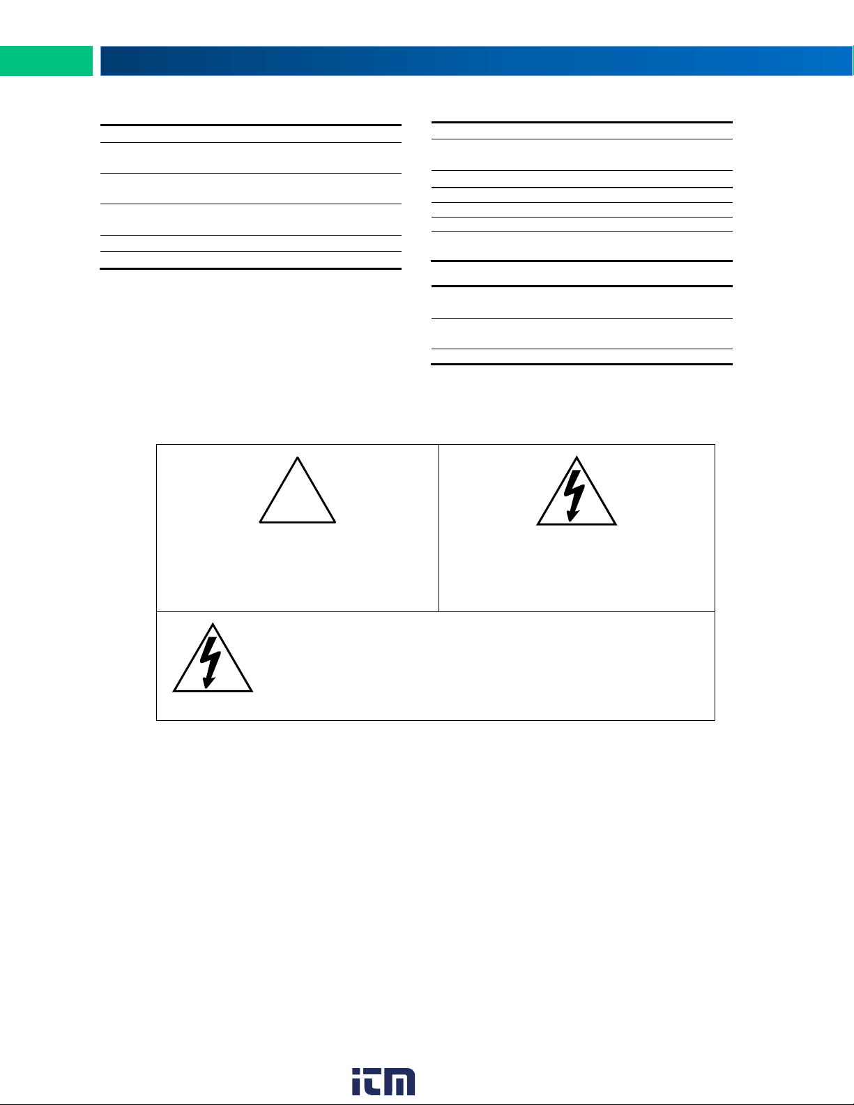
Caution: Read complete instructions
prior to installation and operation of the
device.
Warning: Read all product labels
completely and follow all instructions
and requirements listed on the labels
for installation or service.
Warning!
Installation and service should be performed only by trained service personnel. Service requiring replacement of internal components must be performed at the factory.
!
Wireless Radio
Safety Information
RS-485 Modbus® RTU Serial Comms
PDW Manager Software
Installation
All pushbuttons and wiring connectors are accessed by opening the enclosure. To access electrical connectors, remove the 2 captive screws and remove the display assembly.
Unpacking
Remove both units from box. Inspect the packaging and contents for damage. Report damages, if
any, to the carrier. If any part is missing or the units malfunction, please contact your supplier or
the factory for assistance.
6
www. .com
[email protected]1.800.561.8187
Page 7

PDW30 Point-to-Point Wireless Bridge Instruction Manual
Pre-Installed Conduit Plug
The PDW30 is supplied with one pre-installed optional conduit plug for installations that do not require the
use of both conduit entries. The conduit plug includes an internal hexagonal socket recess for removal.
Mounting Instructions
The PDW30 has two mounting holes that may be used for a 1.5” pipe mounting or wall mounting. Alternatively, the unit may be supported by the conduit using the conduit holes provided. The antenna is
threaded into one of the three conduit holes and may be moved as appropriate for the installation.
It can also be mounted by using the PDA6963 mounting bracket in order to orient the device antenna
away from the pipe. Refer to Mounting Dimensions on page 29 for details on wall or panel space requirements.
Cover Jam Screw
The cover jam screw should be properly installed once the wireless units have been wired and tested in a
safe environment. The cover jam screw is intended to prevent the removal of the units’ cover while in operation without the use of tools. Using a M2 hex wrench, turn the screw clockwise until the screw contacts
the unit. Turn the screw an additional 1/4 to 1/2 turn to secure the cover.
Caution: Excess torque may damage the threads and/or wrench.
FCC Notice
Contains FCC ID: MCQ-XB900HP
The enclosed device complies with Part 15 of the FCC Rules. Operation is subject to the following two
conditions: (i.) this device may not cause harmful interference and (ii.) this device must accept any interference received, including interference that may cause undesired operation.
IMPORTANT
The RF module has been certified for remote and base radio applications. If the module will be used for
portable applications, the device must undergo SAR testing. This equipment has been tested and found
to comply with the limits for a Class B digital device, pursuant to Part 15 of the FCC Rules. These limits
are designed to provide reasonable protection against harmful interference in a residential installation.
This equipment generates, uses and can radiate radio frequency energy and, if not installed and used in
accordance with the instructions, may cause harmful interference to radio communications. However,
there is no guarantee that interference will not occur in a particular installation.
If this equipment does cause harmful interference to radio or television reception, which can be determined by turning the equipment off and on, the user is encouraged to try to correct the interference by
one or more of the following measures: Re-orient or relocate the receiving antenna, Increase the separation between the equipment and receiver. Connect equipment and receiver to outlets on different circuits,
or consult the dealer or an experienced radio/TV technician for help.
Canada (IC) Notice
Contains Model: XB900HP, IC: 1846A-XB900HP
Integrator is responsible for its product to comply with IC ICES-003 & FCC Part 15, Sub. B - Unintentional
Radiators. ICES-003 is the same as FCC Part 15 Sub. B and Industry Canada accepts FCC test report or
CISPR 22 test report for compliance with ICES-003.
7
www. .com
[email protected]1.800.561.8187
Page 8
PDW30 Point-to-Point Wireless Bridge Instruction Manual
• Static electricity can damage sensitive components.
• Observe safe handling precautions for static-sensitive com-
ponents.
• Use proper grounding procedures/codes.
Warning!
• Observe all safety regulations. Electrical wiring should be per-
formed in accordance with all agency requirements and applicable national, state, and local codes to prevent damage to
the device and ensure personnel safety.
Wireless
Module
Connections
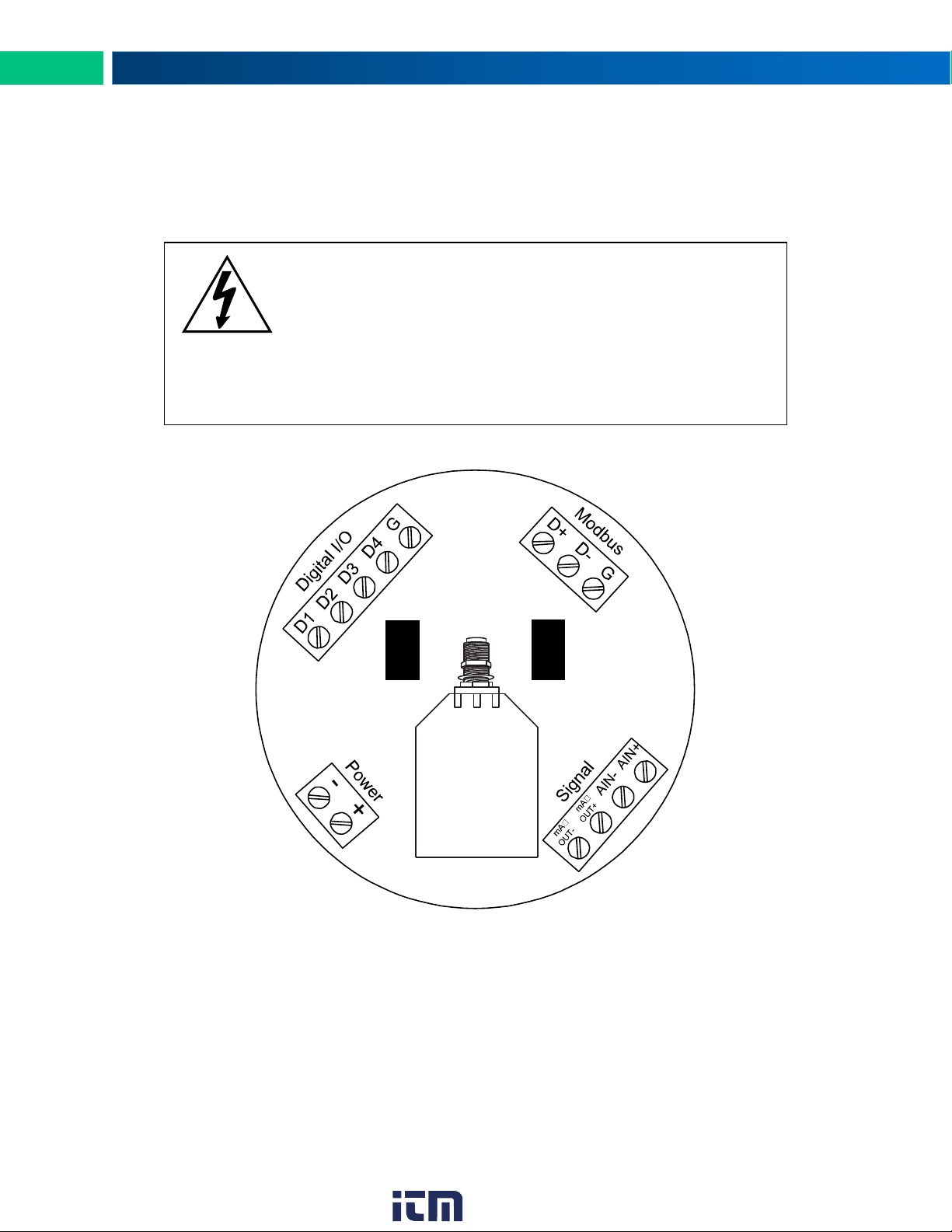
To access the connectors, remove the enclosure cover and unscrew the two captive stainless steel
screws. Remove the electronics assembly from the enclosure. Signal connections are made to removable
terminal blocks on the back of the electronics assembly. Grounding connections are made to the two
ground screws provided on the base – one internal and one external.
Figure 1 below shows the locations of screw terminal blocks on the rear of the wireless unit assembly.
Figure 1. PDW30 Device Assembly, Rear View
8
www. .com
[email protected]1.800.561.8187
Page 9
PDW30 Point-to-Point Wireless Bridge Instruction Manual
Wireless
Module
24 VDC
Power Supply
4-20 mA
2-wire
Transmitter
Wireless
Module
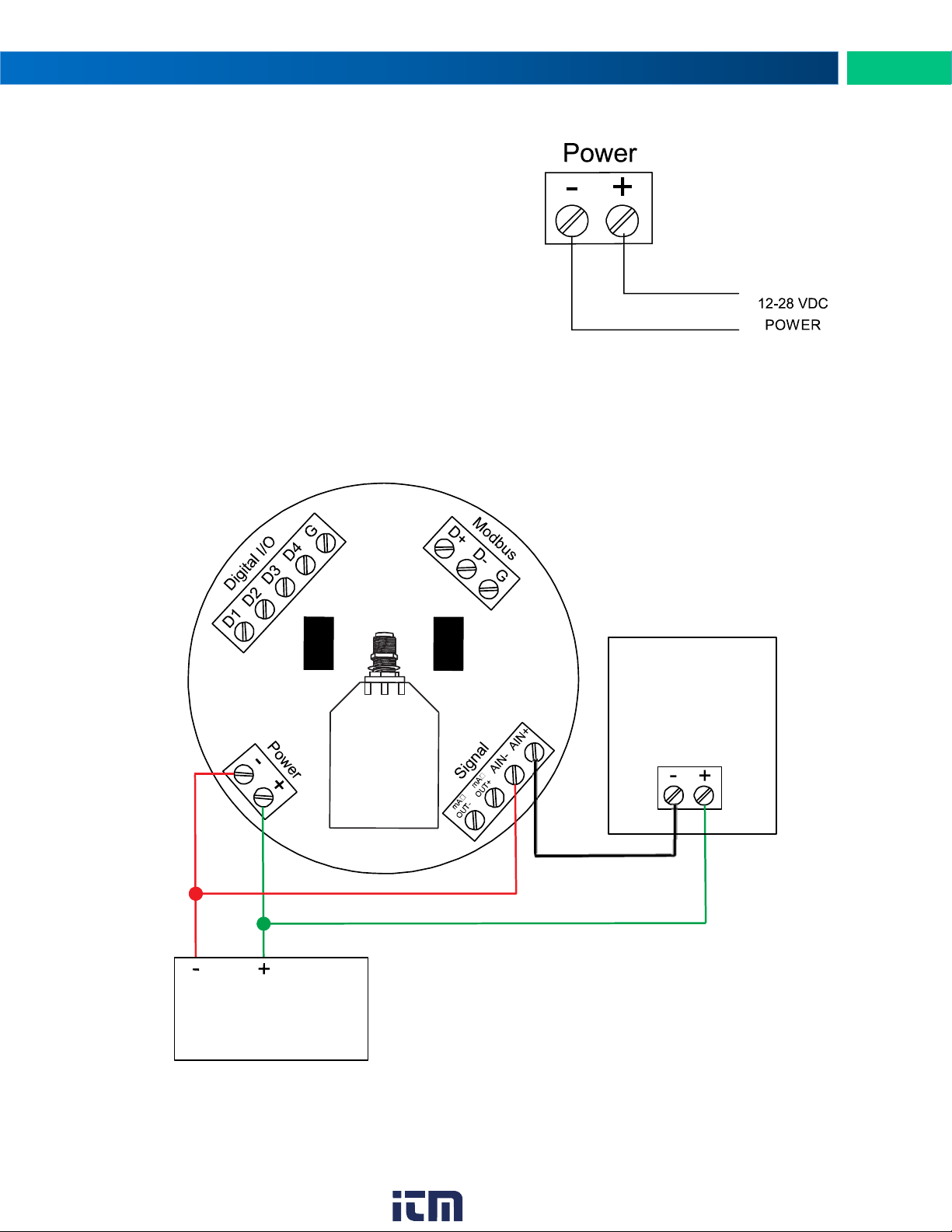
Figure 2. Power Connections
Power Connector
Power connections are made to a two-terminal connector
labeled POWER in Figure 1. The PDW30 is reverse polarity
protected; it will not be damaged if wired backward.
Make sure that the power supply can provide between
12 and 28 VDC to the wireless device.
Power PDW30 and 2-Wire Transmitter from Same Power Supply
The PDW30 wireless units may be powered from the same power supply that powers the 2-wire (looppowered) transmitter, assuming that the supply provides enough voltage for both units. To power both devices from the same supply, wire the devices to the supply as shown below.
Figure 3. PDW30 and 2-Wire Transmitter Powered from Same Supply
www. .com
9
[email protected]1.800.561.8187
Page 10
PDW30 Point-to-Point Wireless Bridge Instruction Manual
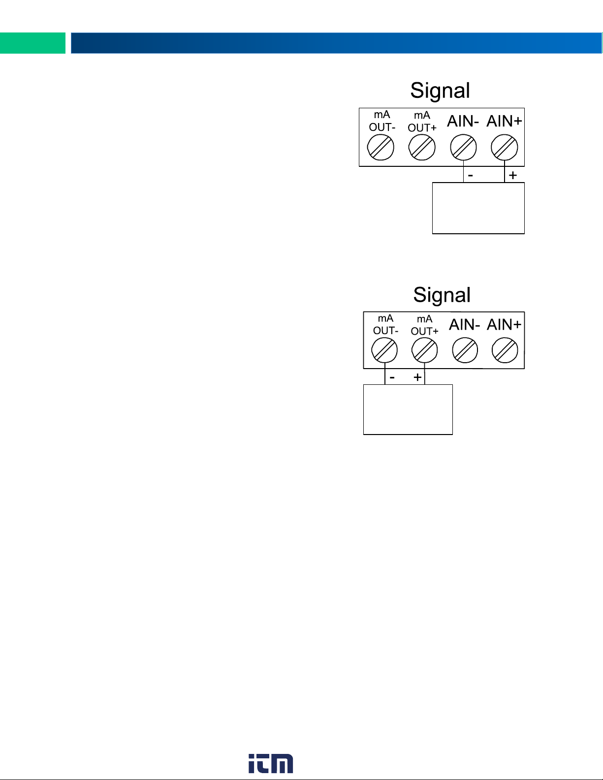
Figure 4. Analog Input
Connections
Figure 5. 4-20 mA Output
Connections
Voltage or
Current Signal
Source
4-20 mA Input
Display, Chart
Recorder, Etc.
Signal Connector
The analog input may be either 4-20 mA, 0-10 V, 0-5 V, or
1-5 V. The appropriate input type must be programmed for
each unit.
Once the appropriate input type has been programmed, wire
the analog signal source to the device as shown in the diagram at right.
The analog input will not interfere with any existing HART signal on a 4-20 mA current loop. However, the HART signal will
not be transmitted wirelessly.
4-20 mA Output Connector
The 4-20 mA output corresponds with the analog input signal
on the paired wireless device. The analog output signal is always 4-20 mA, regardless of the input type on the other wireless module.
For instance, if the analog input type on the first device was
0-10 V and the input value was 5 V, the second device would
output 12 mA.
Connect the mA OUT terminals to a device scaled to read a
4-20 mA signal.
The analog output is internally powered; no external power
supply is required.
10
www. .com
[email protected]1.800.561.8187
Page 11
PDW30 Point-to-Point Wireless Bridge Instruction Manual
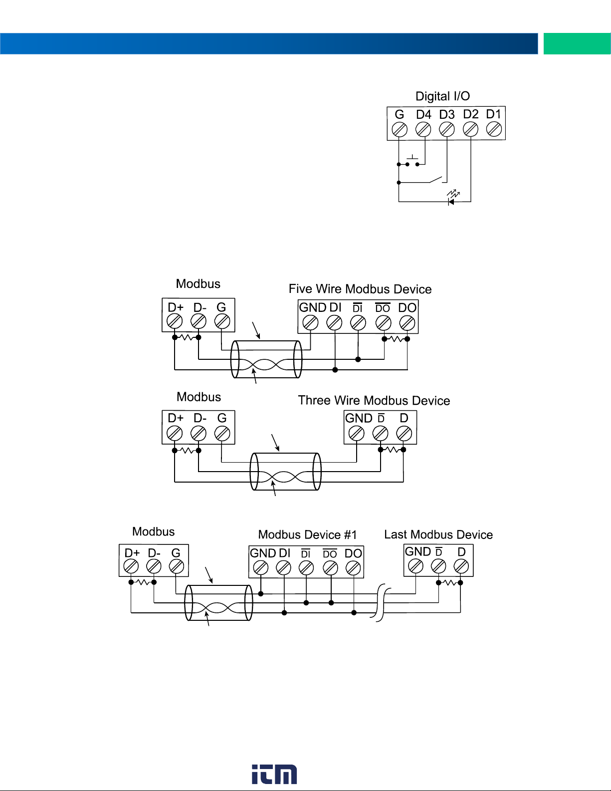
Figure 7. Three- and Five-Wire RS-485 Modbus Connections
Figure 8. Multiple Device RS-485 Modbus Connection
Shield
Twisted-Pair
Shield
Twisted-Pair
(PDW30 Wireless Unit)
(PDW30 Wireless Unit)
R
R
R
R
Shield
Twisted-Pair
(PDW30 Wireless Unit)
R
R
Figure 6. Digital I/O Connections
Digital I/O Connector
All digital connections are referenced to ground. The primary
unit digital I/O settings determine the settings of the secondary unit (e.g. if D1 of the primary unit is an input then D1 of
the secondary unit in an output).
Note: Each connection may be set independently in the de-
vice settings as either an input or an output. In the diagram to the right, D4 & D3 are digital inputs and D2 is a
digital output.
Modbus RTU Serial Communications
The PDW30 acts as a simple pass-through for Modbus communications. As such, multiple Modbus enabled devices may be transmitted wirelessly using the PDW30 Wireless Bridge.
Note: Modbus Master must be connected to Primary Wireless Unit.
Notes:
1. Termination resistors are optional and values depend on the cable length and characteristic impedance. Consult the cable manufacturer for recommendations.
2. Use shielded cable, twisted-pairs plus ground. Connect ground shield only at one location.
www. .com
11
[email protected]1.800.561.8187
Page 12

PDW30 Point-to-Point Wireless Bridge Instruction Manual
The units are factory calibrated prior to shipment to read
in milliamps or volts depending on the input selection.
The calibration equipment is certified to NIST standards.
Primary
Secondary
Setup and Programming
Overview
There are no jumpers to set for wireless device input selection.
Setup and programming is done through the programming buttons located underneath the enclosure
cover or using the PDW Manager software. After power and input signal connections have been completed and verified, apply power to the device.
12
www. .com
[email protected]1.800.561.8187
Page 13
PDW30 Point-to-Point Wireless Bridge Instruction Manual
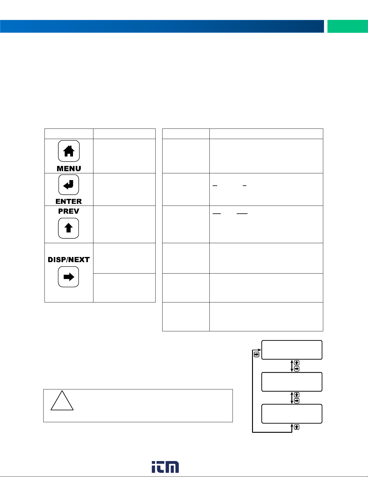
Button
Description
Display
Status
Menu
Enter or exit the device menu
RSSI
Received Signal Strength Indicator
Indicates the wireless signal strength
between wireless devices on a scale of
1 to 10.
Enter
Select a menu item
of option
RT
Receiving/Transmitting
Flashes while the devices are sending
and/or receiving data
Previous
Cycle backward
through menus or increment digit
PRI /
SEC
Primary/Secondary
Indicates whether the device is the primary unit or the secondary unit. This
distinction is fixed and cannot be
changed.
Next
Cycle forward
through menus or
select next digit
LINK OK /
CONNECTING
Link Status
Displays whether or not the units are
currently connected
Display
Show current inputs
and outputs
AIN /
AOUT
Analog Input/Analog Output
Labels for the current analog input and
analog output
(Shown when the display button is pressed)
DI /
DO
Digital Input/Digital Output
Labels for each of the current digital inputs or outputs
(Shown when the display button is pressed twice)
CAUTION
The wireless transmission is interrupted while the unit
is in Programming Mode. Press Menu to return to Run
Mode.
!
LINK OK
PRI RSSI 10 RT
AOUT: 20.00 mA
AIN: 20.00 mA
DO3:OFF DI4:OFF
DI1:ON DO2:ON
Programming Buttons
The units can be programmed using the buttons located behind the enclosure cover. Use the menu but-
ton to enter or exit programming mode, the next button to cycle forward through menu options, the previ-
ous button to cycle backward through menu options, and the enter button to select the menu item or op-
tion you want.
During number entry, use the next button to select a digit and the previous button to increment the se-
lected digit.
Press the display button while in run mode to show the current analog and digital inputs and outputs.
Quick Tip
While programming the wireless units, it may be useful to view the current
signal or digital I/O in order to ensure that the correct signals are reaching
the units. Pressing either the previous or display buttons while the device is
in run mode will cycle through the unit’s display modes which are, in order,
link status, analog I/O, and digital I/O.
www. .com
13
[email protected]1.800.561.8187
Page 14

PDW30 Point-to-Point Wireless Bridge Instruction Manual
PDW Manager Software
The units can also be programmed using the PC based PDW Manager. Units connect to a PC via the mi-
cro USB connection on their face, underneath the enclosure cover.
Use of PDW Manager is required for programming advanced settings, such as wireless encryption, and
analog signal calibration.
Note: Units must be powered externally prior to programming via USB.
Instructions on the use of PDW Manager to program the PDW30 wireless units can be found under Programming with PDW Manager on page 22.
14
www. .com
[email protected]1.800.561.8187
Page 15

PDW30 Point-to-Point Wireless Bridge Instruction Manual
Display
Action/Setting Description
ANALOG INPUT SETUP
Change the analog input type
ANALOG INPUT
Displays the current analog input type (press enter to change)
4-20mA
Set the analog input to 4-20 mA
0-10V
Set the analog input to 0-10 V
0-5V
Set the analog input to 0-5 V
1-5V
Set the analog input to 1-5 V
BACK TO SETUP MENU
Return to the setup menu
DIGITAL IO SETUP
Change whether each digital connection is an input or an output
DIGITAL I/O #1
Displays digital connection #1’s current setting (press enter to change)
INPUT
Set the selected digital connection to input
OUTPUT
Set the selected digital connection to output
DIGITAL I/O #2
Displays digital connection #2’s current setting (press enter to change)
DIGITAL I/O #3
Displays digital connection #3’s current setting (press enter to change)
DIGITAL I/O #4
Displays digital connection #4’s current setting (press enter to change)
BACK TO SETUP MENU
Return to the setup menu
NETWORK AND MODBUS SETUP
Change settings related to wireless network and Modbus® input
NETWORK ID
Displays the point-to-point wireless network ID (press enter to change)
01-99
The network ID can be any number between 01 and 99
MODBUS TIMEOUT
Displays the Modbus timeout setting (press enter to change)
1 SEC
1 second timeout
2 SEC
2 second timeout
3 SEC
3 second timeout
4 SEC
4 second timeout
5 SEC
5 second timeout
0.5 SEC
0.5 second timeout
MODBUS BAUD RATE
Displays the Modbus baud rate setting (press enter to change)
9.6K
9.6 K baud rate
19.2k
19.2 K baud rate
28.8k
28.8 K baud rate
38.4k
38.4 K baud rate
57.6k
57.6 K baud rate
1.2k
1.2 K baud rate
2.4k
2.4 K baud rate
4.8k
4.8 K baud rate
Display Functions & Messages
Shown below is a list of all display messaged in each device’s setup menu. This list is in order of appear-
ance when pressing the next button. An indented line indicates a sub-menu or item.
Primary Unit
www. .com
15
[email protected]1.800.561.8187
Page 16

PDW30 Point-to-Point Wireless Bridge Instruction Manual
Display
Action/Setting Description
DATA FORMAT
Displays the Modbus data format setting (press enter to change)
8E1
Data format 8E1
8O1
Data format 8O1
8N2
Data format 8N2
BACK TO SETUP MENU
Return to the setup menu
PASSWORD SETUP
Change the device password
PASSWORD (0=OFF)
Displays the current device password (press enter to change)
0000-9999
Password can be any number from 0001 to 9999 (0000 disables)
BACK TO SETUP MENU
Return to the setup menu
RESTORE DEFAULTS
Restore the unit to factory default settings
LOAD DEFAULTS?
Factory restoration confirmation prompt
NO
No, do not restore the device to factory defaults (press enter)
YES
Yes. restore the device to factory defaults (press enter)
Display
Action/Setting Description
NETWORK ID
Displays the point-to-point wireless network ID (press enter to change)
01-99
The network ID can be any number between 01 and 99
ANALOG INPUT
Displays the current analog input type (press enter to change)
4-20mA
Set the analog input to 4-20 mA
0-10V
Set the analog input to 0-10 V
0-5V
Set the analog input to 0-5 V
1-5V
Set the analog input to 1-5 V
MODBUS TIMEOUT
Displays the Modbus timeout setting (press enter to change)
0.2 SEC
0.2 second timeout
0.5 SEC
0.5 second timeout
1 SEC
1 second timeout
0.1 SEC
0.1 second timeout
PASSWORD SETUP
Change the device password
PASSWORD (0=OFF)
Displays the current device password (press enter to change)
0000-9999
Password can be any number from 0001 to 9999 (0000 to disable)
BACK TO SETUP MENU
Return to the setup menu
RESTORE DEFAULTS
Restore the unit to factory default settings
LOAD DEFAULTS?
Factory restoration confirmation prompt
NO
No, do not restore the device to factory defaults (press enter)
YES
Yes. restore the device to factory defaults (press enter)
Secondary Unit
16
www. .com
[email protected]1.800.561.8187
Page 17
PDW30 Point-to-Point Wireless Bridge Instruction Manual
LINK OK
PRI RSSI 10 RT
SETUP
ANALOG INPUT
SETUP
DIGITAL IO
MODBUS SETUP
NETWORK AND
SETUP
PASSWORD
DEFAULTS
RESTORE
Run Mode
LINK OK
SEC RSSI 10 RT
NOW: 01
NETWORK ID
NOW: 4-20mA
ANALOG INPUT
NOW: 0.2 SEC
MODBUS TIMEOUT
SETUP
PASSWORD
DEFAULTS
RESTORE
Run Mode
NOW: 01
NETWORK ID
SET: 01
NETWORK ID
SET: 11
NETWORK ID
SET: 11
NETWORK ID
SET: 12
NETWORK ID
Access
edit mode
Increment
selected digit
Select the
next digit
Increment
selected digit
Accept
new value
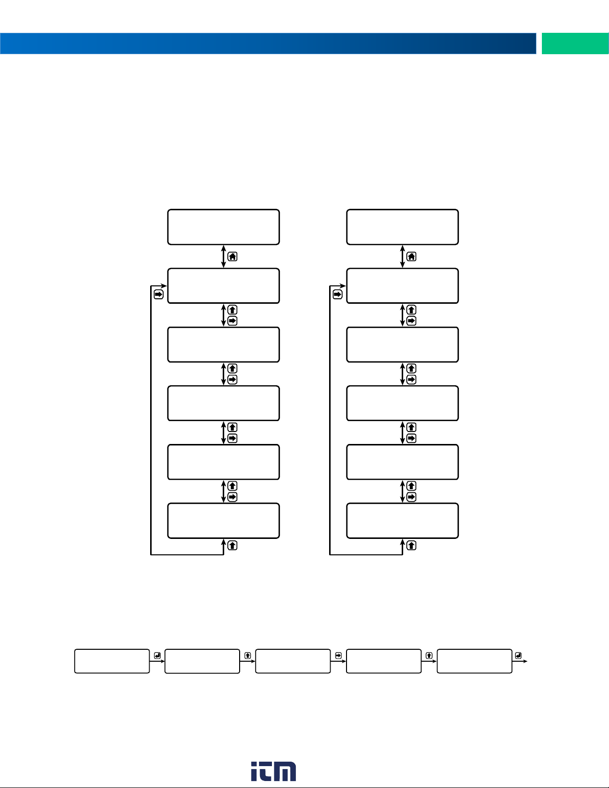
Setup Menu
The setup menu consists of analog, digital (discrete), and Modbus® input/output settings, network ID,
password, and factory defaults restoration.
The primary wireless unit determines network protocol and digital I/O settings for the secondary unit, simplifying the setup process. For instance, if a digital connection is programmed to be an input on the pri-
mary unit, that same connection will be an output on the secondary unit. Because of this, the secondary
wireless unit has fewer menu options than the primary unit.
Primary Device Secondary Device
Numeric values are set using the next and previous buttons. Press next to select next digit and previous
to increment digit value.
The selected digit will flash.
Press the enter button, at any time, to accept the value or the menu button to exit without saving.
Entering Numeric Values
www. .com
[email protected]1.800.561.8187
17
Page 18
PDW30 Point-to-Point Wireless Bridge Instruction Manual
SETUP
ANALOG INPUT
NOW: 4-20mA
ANALOG INPUT
SETUP MENU
BACK TO
SET: 4-20mA
ANALOG INPUT
SET: 0-10V
ANALOG INPUT
SET: 0-5V
ANALOG INPUT
SET: 1-5V
ANALOG INPUT
SETUP
DIGITAL IO
NOW: INPUT
DIGITAL I/O #1
NOW: INPUT
DIGITAL I/O #2
NOW: INPUT
DIGITAL I/O #3
NOW: INPUT
DIGITAL I/O #4
SETUP MENU
BACK TO
SET: INPUT
DIGITAL I/O #1
SET: OUTPUT
DIGITAL I/O #1
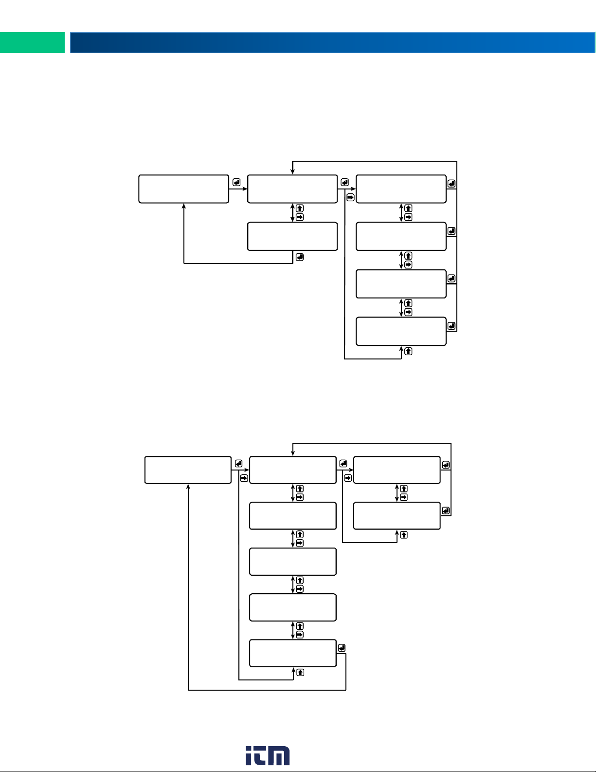
Primary Device Menus
Analog Input Setup
Enter the Analog Input menu to set up the wireless unit to accept either a current or a voltage input.
The current input is capable of accepting a signal from 4 to 20 mA. The voltage input is capable of accepting a 0 to 10 VDC signal, 0 to 5 VDC signal, or 1-5 VDC signal.
Digital I/O Setup
All four digital connections may be set as either inputs or outputs. The setting on the primary unit determines the corresponding digital connection on the secondary unit. For instance, if digital connection number one is set as an input on the primary unit, it will be an output on the secondary unit.
Each digital connection may be set independently as either an input or output.
18
www. .com
[email protected]1.800.561.8187
Page 19
PDW30 Point-to-Point Wireless Bridge Instruction Manual
MODBUS SETUP
NETWORK AND
NOW: 01
NETWORK ID
NOW: 1 SEC
MODBUS TIMEOUT
NOW: 9.6K
MODBUS BAUD RATE
NOW: 8E1
DATA FORMAT
SETUP MENU
BACK TO
SET: 01
NETWORK ID
SET: 1 SEC
MODBUS TIMEOUT
SET: 2 SEC
MODBUS TIMEOUT
SET: 3 SEC
MODBUS TIMEOUT
SET: 4 SEC
MODBUS TIMEOUT
SET: 5 SEC
MODBUS TIMEOUT
SET: 0.5 SEC
MODBUS TIMEOUT
SET: 9.6K
MODBUS BAUD RATE
SET: 19.2k
MODBUS BAUD RATE
SET: 28.8k
MODBUS BAUD RATE
SET: 38.4k
MODBUS BAUD RATE
SET: 57.6k
MODBUS BAUD RATE
SET: 1.2k
MODBUS BAUD RATE
SET: 2.4k
MODBUS BAUD RATE
SET: 4.8k
MODBUS BAUD RATE
SET: 8E1
DATA FORMAT
SET: 8O1
DATA FORMAT
SET: 8N2
DATA FORMAT
increments selected dig it.
selects next digit to the rig ht.
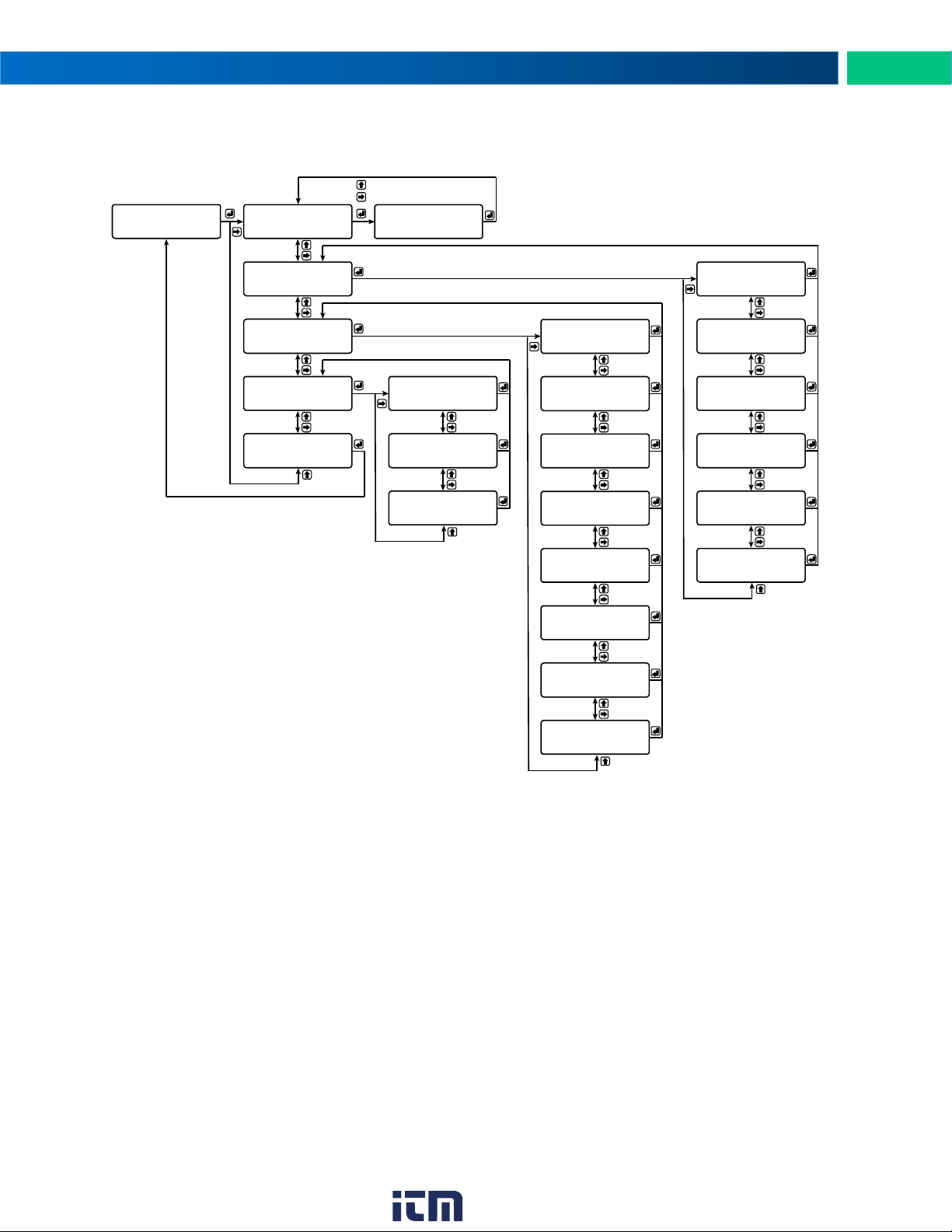
Network and Modbus Setup
The Network and Modbus Setup menu is where the wireless device’s Network ID is set and Modbus
rial communications settings are programmed.
®
se-
The network ID determines primary and secondary wireless pairs. The primary and secondary
units must share the same unique network ID in order to communicate.
Network ID
Modbus Timeout
The Modbus timeout sets the length of time the wireless devices will wait for a reply from the
other Modbus device before returning an error. This should be 1 to 2 seconds at 9600 bps on the
primary device.
Modbus Baud Rate
The baud rate of the wireless devices must match the baud rate of the Modbus network in order
to prevent collisions on the bus. The baud rate may be set between 1,200 and 57,600 bps.
Data Format
The data format of the wireless devices must match the data format of the Modbus network. Set
the data format to either 8E1 (8-bit, even parity, 1 stop bit), 8O1 (8-bit, odd parity, 1 stop bit), or
8N2 (8-bit, no parity, 2 stop bits).
www. .com
19
[email protected]1.800.561.8187
Page 20
PDW30 Point-to-Point Wireless Bridge Instruction Manual
Did you forget the password?
The password may be disabled by entering a master
password. If you are authorized to make changes, enter
the master password 7300 to unlock the device.
SETUP
PASSWORD
NOW: 0000
PASSWORD (0=OFF)
SETUP MENU
BACK TO
SET: 0123
PASSWORD (0=OFF)
increments selected digit.
selects next digit to the rig ht.
0000 disables the password.
LINK OK
PRI RSSI 10 RT
0000
ENTER PASSWORD
Run Mode
ACCESS GRANTED
increments selected digit.
selects next digit to the right.
TRY AGAIN
ENTER PASSWORD
1 Sec
If Incorrect
DEFAULTS
RESTORE
NO
LOAD DEFAULTS?
YES
LOAD DEFAULTS?
Unit will load default
setting s and reboot.
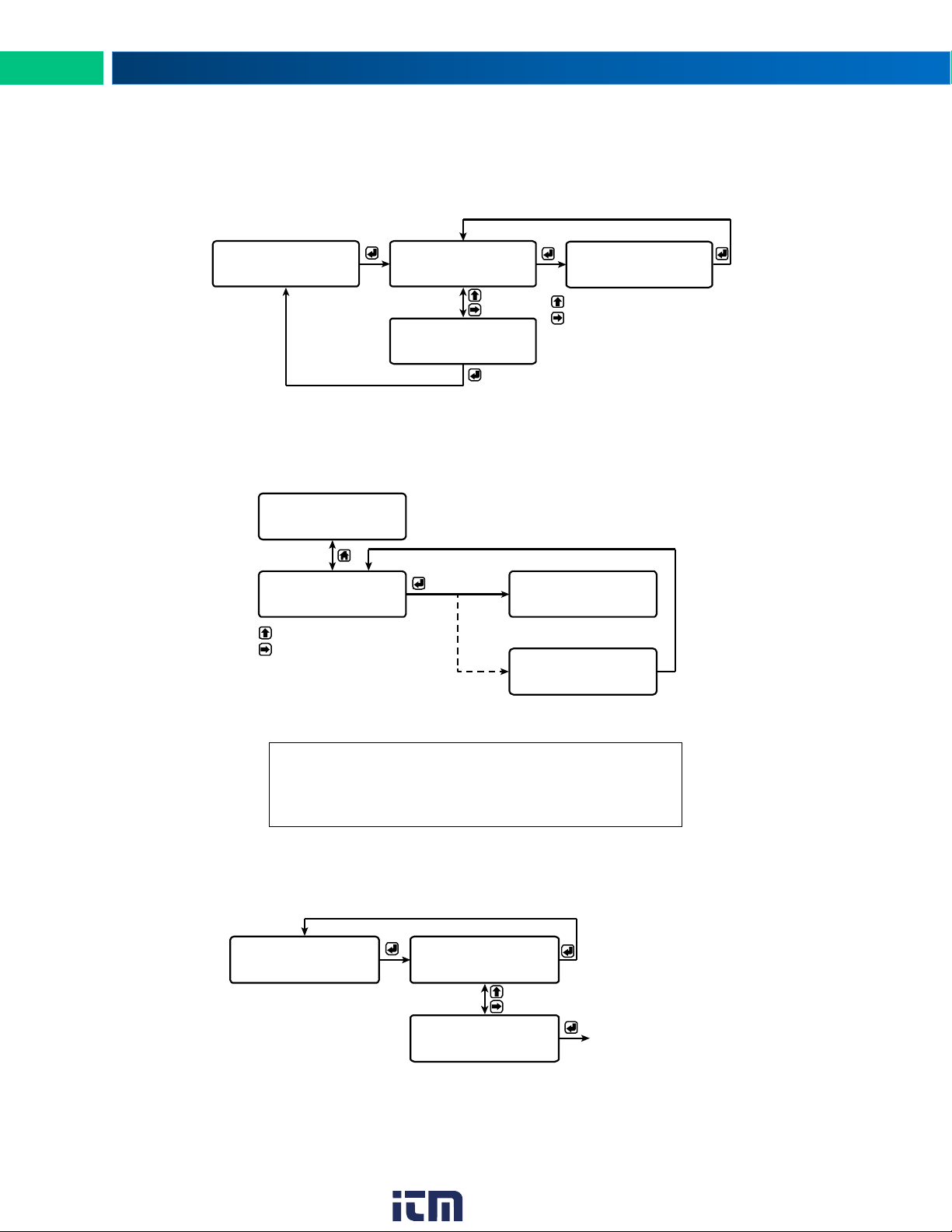
Password Setup
Both the primary and secondary wireless units may be protected with a four digit numeric password in order to prevent unauthorized tampering. When a password has been set, you will be prompted to enter
that password in order to access the device menu.
To disable password protection, simply enter 0000 as the password.
Note: See Entering Numeric Values on page 17 for instructions on how to enter numbers
Making Changes to a Password Protected Wireless Unit
Once a password has been set on the device, you will be required to enter that password before being
allowed to access the device menu.
Note: Setting a password will require you to enter the password to access the device settings via the PC
software as well.
Restore Defaults
If a mistake has been made while programming the primary or secondary device, and it is unclear where
the error occurred, the best option may be to perform a factory reset of the device and begin again.
20
www. .com
[email protected]1.800.561.8187
Page 21
PDW30 Point-to-Point Wireless Bridge Instruction Manual
LINK OK
SEC RSSI 10 RT
NOW: 01
NETWORK ID
NOW: 4-20mA
ANALOG INPUT
NOW: 0.2 SEC
MODBUS TIMEOUT
SETUP
PASSWORD
DEFAULTS
RESTORE
Run M ode
SET: 01
NETWORK ID
increments selected digit.
selects next dig it to the rig ht.
SET: 4-20mA
ANALOG INPUT
SET: 0-10V
ANALOG INPUT
SET: 0-5V
ANALOG INPUT
SET: 1-5V
ANALOG INPUT
NOW: 0000
PASSWORD (0=OFF)
SETUP MENU
BACK TO
SET: 0123
PASSWORD (0=OFF)
increments selected digit.
selects next dig it to the rig ht.
0000 disables the password.
NO
LOAD DEFAULTS?
YES
LOAD DEFAULTS?
Unit wil l load default
setting s and reboots.
SET: 0.2 SEC
MODBUS TIMEOUT
SET: 0.5 SEC
MODBUS TIMEOUT
SET: 1 SEC
MODBUS TIMEOUT
SET: 0.1 SEC
MODBUS TIMEOUT
LINK OK
PRI RSSI 10 RT
AOUT: 20.00 mA
AIN: 20.00 mA
DO3:OFF DI4:OFF
DI1:ON DO2:ON
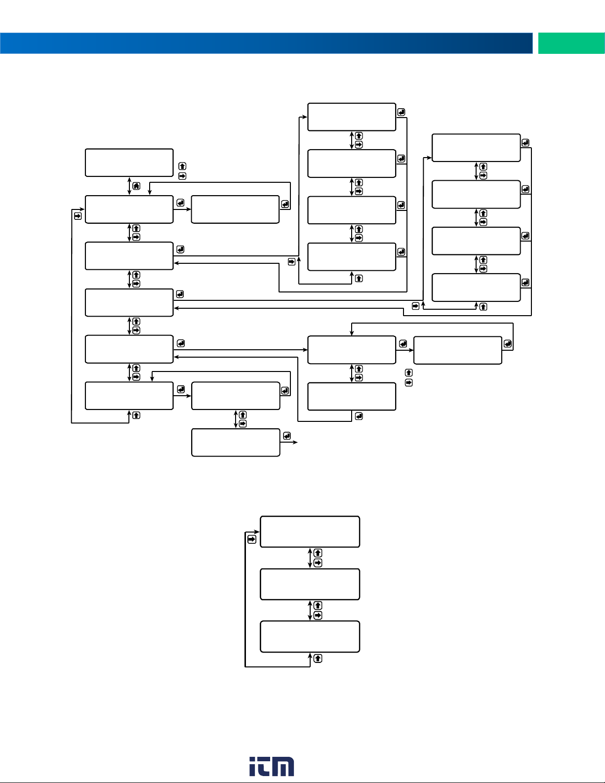
Secondary Device Menus
The secondary device has fewer menu options than the primary device, shown below.
Pressing either the previous or display buttons while the device is in run mode will cycle through the display modes. These modes are, in order, link status, analog I/O, and digital I/O.
Display Signal I/O and Digital I/O Status
www. .com
[email protected]1.800.561.8187
21
Page 22
PDW30 Point-to-Point Wireless Bridge Instruction Manual
PRI RSSI 10 RT
LINK OK
12-28 VDC
Programming with PDW Manager
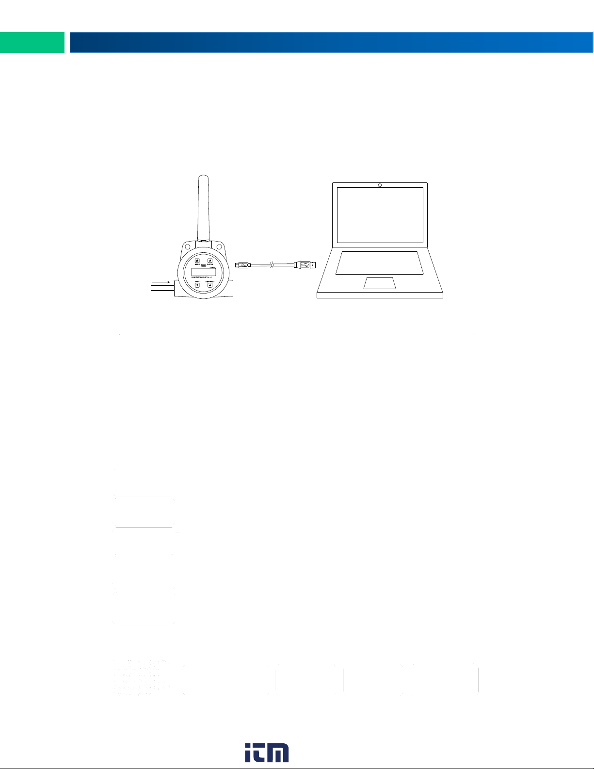
PDW Manager allows you to program the PDW30 wireless units from a PC with a USB connection. Units
connect to a PC via the micro USB connection on their face, underneath the enclosure cover. Use of
PDW Manager is required for programming advanced settings such as wireless encryption and analog
signal calibration.
.
Once the software is running, power the unit using a 12-28 VDC power supply and connect the device to
the PC using the provided USB cable.
The PC will automatically install the appropriate device drivers. Once this has completed, the device will
appear in the Device list at the top of the PDW Manager window. Click Connect.
The menu options displayed will vary depending on what type of unit is connected. The PDW30 primary
unit will have more options than the secondary unit. The image below shows the available options on the
configuration tab while the primary unit is connected.
22
www. .com
[email protected]1.800.561.8187
Page 23

PDW30 Point-to-Point Wireless Bridge Instruction Manual
Calibration – Analog Input
Calibration – 4-20mA Output
The devices’ analog inputs and outputs can be calibrated using the Calibration tabs. The IO Testing tab
allows you to perform diagnostics and testing on the units.
23
www. .com
[email protected]1.800.561.8187
Page 24
PDW30 Point-to-Point Wireless Bridge Instruction Manual
IO Testing
Device communication can be secured by enabling 128-bit AES encryption. A channel mask may also be
set for interference immunity. The encryption key and channel mask may be entered on the Advanced
tab.
Once you have entered the
encryption information, click
Save Settings. The wireless
devices must share identi-
cal encryption keys in order
to communicate, so be sure
to enter the same infor-
mation for
the second
unit.
24
www. .com
[email protected]1.800.561.8187
Page 25
PDW30 Point-to-Point Wireless Bridge Instruction Manual
Symptom
Possible Cause
Corrective Action
Devices will not connect.
Devices have
mismatched network IDs.
• Devices will not connect if they do not have
the same network ID. Verify that both devices
share the same network ID.
Devices are out of
range or there are
obstacles blocking the wireless
path.
• Bring devices closer together to see if it alleviates the issue. Units will display LINK OK if
they are connected. If devices connect, consider placing closer together permanently, removing any obstacles, or mounting higher.
• Ensure antennas are on parallel plane. Devices that are vertically separated will not
have as strong of a connection.
• If communicating over distance of miles, consider installing PDW30-RNA repeaters or a
high gain directional antenna.
Multiple wireless
devices in the
area with the
same ID.
• If there are multiple PDW30 wireless bridges,
verify that each pair has its own unique network ID.
Encryption keys
do not match
• If using encryption, ensure that the encryption keys on both devices match exactly.
Intermittent signal issues.
Signal is too poor.
• Check RSSI. If signal is too low, consider
moving devices closer together, clearing obstacles in wireless path, or mounting devices
higher.
• Ensure devices are on parallel plane.
• If communicating over distance of miles, consider installing high gain directional antenna.
Temporary obstacles are blocking
the wireless path.
• Temporary obstacles, such as large trucks or
heavy equipment, can interfere with wireless
path. Consider moving wireless units higher
or to an area with less traffic.
?
Troubleshooting
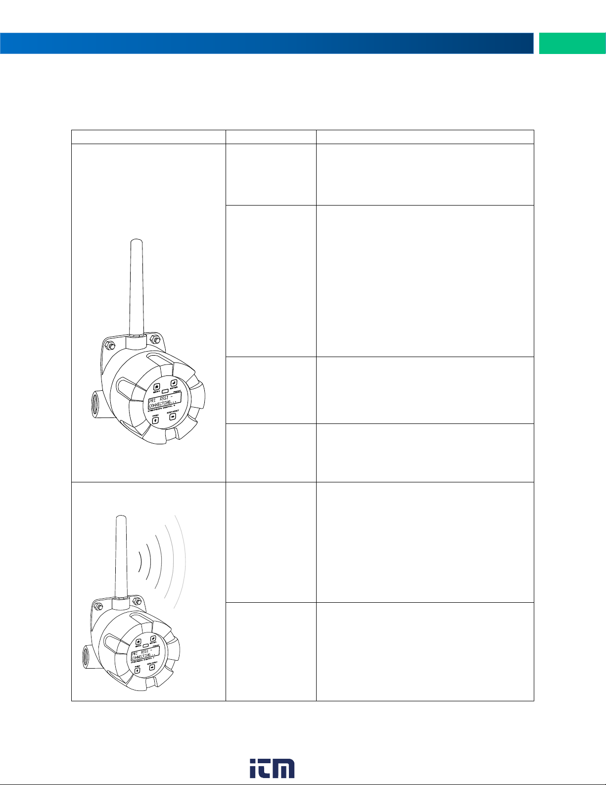
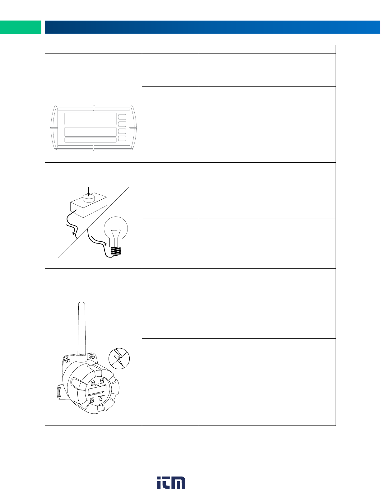
If you are experiencing difficulties with your wireless installation, consult the troubleshooting steps listed
below. For best results, identify the symptoms of the problem you are having and attempt all of the corrective actions listed for the particular symptom.
www. .com
25
[email protected]1.800.561.8187
Page 26
PDW30 Point-to-Point Wireless Bridge Instruction Manual
Symptom
Possible Cause
Corrective Action
Destination device reads out
of range, zero, or incorrect.
Wireless device
has mismatched
input type.
• Make sure that input type on the device is
correct for the analog input being used. Options are 4-20 mA, 0-10 V, 0-5 V, or 1-5 V.
Destination device is not scaled
properly.
• Destination device must accept 4-20 mA signal and be scaled to properly display the signal. Check the manufacturer’s instruction
manual for how to do this.
Signal connections are improperly wired.
• Double check to make sure all of the signal
connections are properly wired to all devices.
Check wiring diagrams starting on page 8.
Digital inputs are not corre-
sponding with digital outputs.
Devices have
mismatched input/output settings.
• Check to make sure the digital connection is
programmed appropriately as either an input
or an output.
Devices are improperly wired.
• Check to make sure all digital inputs and outputs are properly wired to all devices. Check
wiring diagrams starting on page 8.
Device will not power on.
Not enough voltage is coming
from the power
supply.
• Devices require at least 12 VDC each in order to power on. Check that the power supply
is providing enough voltage to the device and
that there are not too many devices drawing
power from the supply.
Devices are improperly wired.
• Check to make sure all power connections
are properly wired to all devices. Check wiring diagrams starting on page 8.
999999
Feet
ON
OFF
26
www. .com
[email protected]1.800.561.8187
Page 27
PDW30 Point-to-Point Wireless Bridge Instruction Manual
Symptom
Possible Cause
Corrective Action
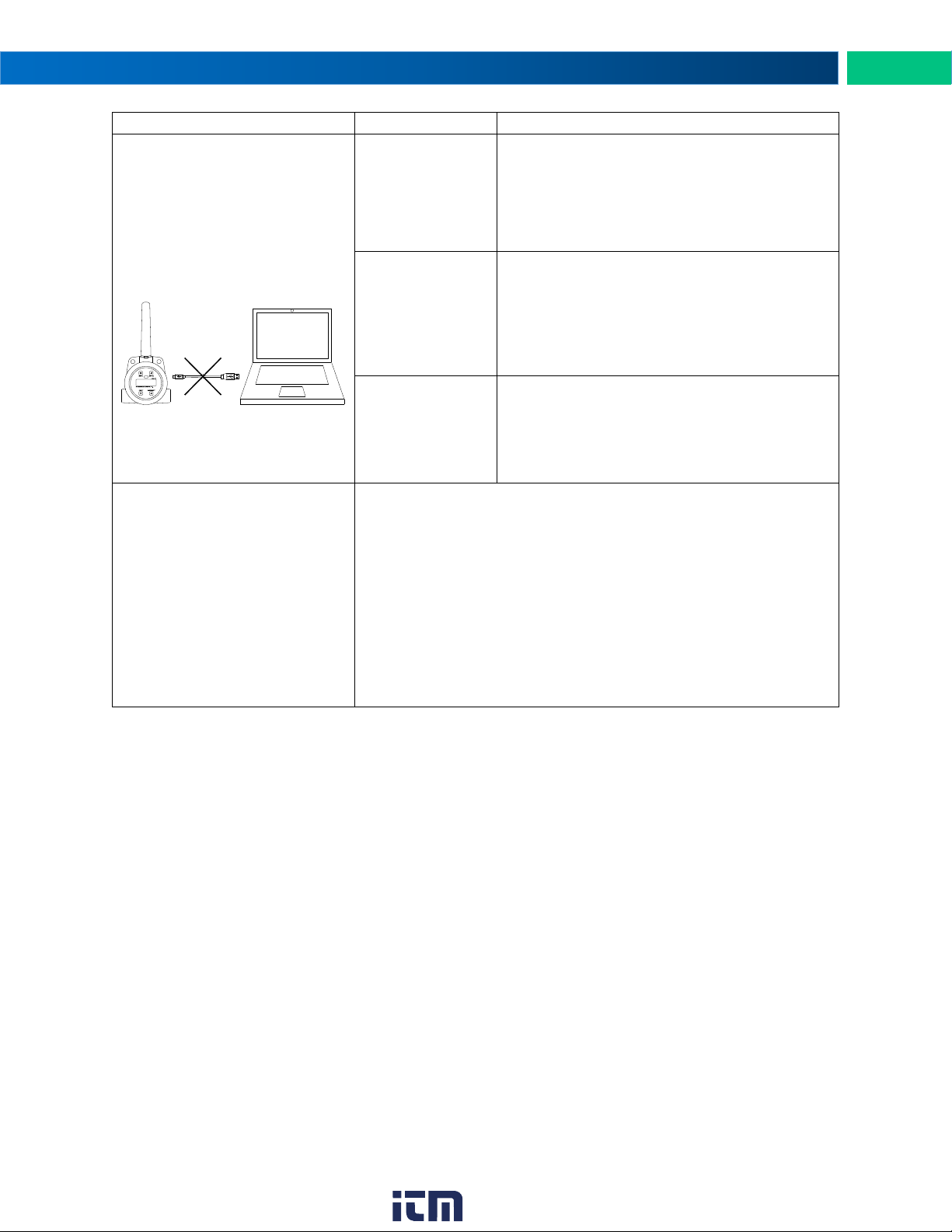
Device will not connect to PC
via USB
Wireless device is
not powered.
• The device must be powered by a
12-28 VDC power supply in order for the PC
to recognize it. Power the wireless device
and try again.
Software version
is outdated
• Check that you are running the latest software version. The latest version of PDW
.
USB cable is
faulty
• Try connecting the wireless device using a
known good micro USB cable. Any standard
USB A to micro USB B cable, such as the
one used to charge a smartphone, should
work.
Other Issue
?
If you are experiencing a symptom not listed here, or the suggested
troubleshooting steps do not alleviate your problem, please attempt
to restore the wireless devices to system defaults by following the
instructions on page 20. If you require technical support, please
contact us at:
PRI RSSI 10 RT
LINK OK
www. .com
27
[email protected]1.800.561.8187
Page 28
PDW30 Point-to-Point Wireless Bridge Instruction Manual
Parameter
Default Setting
User Setting
ANALOG INPUT
4-20mA
DIGITAL I/O #1
INPUT
DIGITAL I/O #2
INPUT
DIGITAL I/O #3
INPUT
DIGITAL I/O #4
INPUT
NETWORK ID
01 MODBUS TIMEOUT
1 SEC
MODBUS BAUD RATE
9.6K
DATA FORMAT
8E1
PASSWORD
0000
Parameter
Default Setting
User Setting
NETWORK ID
01
ANALOG INPUT
4-20mA
MODBUS TIMEOUT
0.2 SEC
PASSWORD
0000
Factory Defaults & User Settings
The following table shows the factory setting for most of the programmable parameters on the device.
Next to the factory setting, the user may record the new setting for the particular application.
Model: ___________________ S/N: __________________ Date: _______________
Primary
28
Secondary
www. .com
[email protected]1.800.561.8187
Page 29
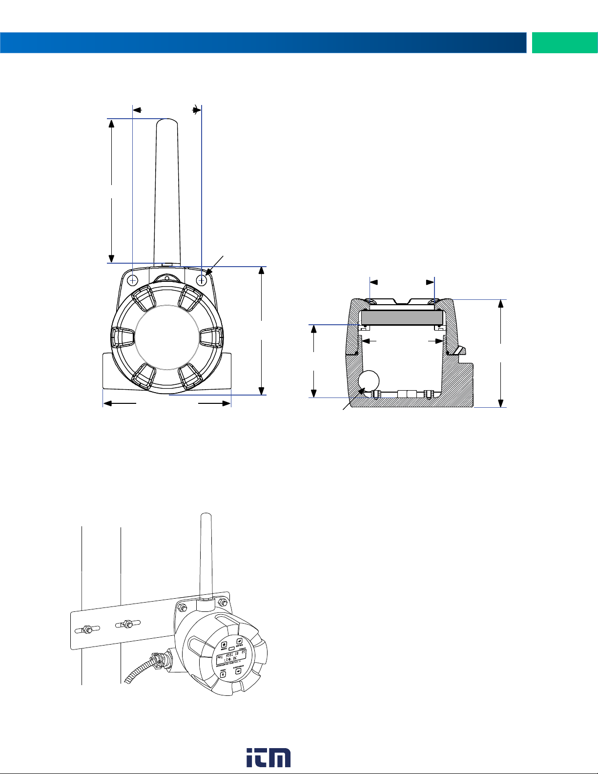
Mounting Dimensions
Figure 9. Enclosure Dimensions – Front
View
Figure 10. Enclosure Dimensions – Side
Cross Section View
Ø 0.35 (Ø 9.0)
2.31 (58.6)
4.30 (109.2)
4.27 (108.4)
2.44 (61.9)
2.74 (69.7)
3.62 (92.0)
2.17 (55.0)
½" NPT
4.00 (101.6)
Pipe
PDA6963
PDW30 Point-to-Point Wireless Bridge Instruction Manual
Note: The supplied conduit plug may extend up to 0.6 in [15 mm] from the conduit opening when installed.
PDA6963 Stainless Steel Pipe Mounting Kit
Figure 11. PDA6963 Stainless Steel Pipe
Mounting Kit
29
www. .com
[email protected]1.800.561.8187
 Loading...