

Page 1
Serial Communication Converters & Adapters
Instruction Manual
PRECISION DIGITAL CORPORATION
233 South Street • Hopkinton MA 01748 USA
Tel (800) 343-1001 • Fax (508) 655-8990
www.predig.com
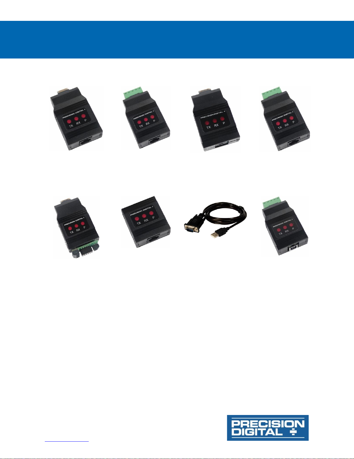
PDA1232 PROVU RS-232
Serial Adapter
PDA1485 PROVU RS-485
Serial Adapter
PDA7232 Trident RS-232
Serial Adapter
PDA7422 Trident RS-485
Serial Adapter
PDA7485 RS-232 to
RS-485 Converter
PDA8006 Trident to USB
Serial Adapter
PDA8008 PROVU to USB
Serial Adapter
PDA8232 USB to RS-232
Converter
PDA8485 USB RS-485
Converter
• Provide Convenient Way to Bring Data from Meter Into PC, PLC, etc.
• RS-232 and RS-485 Adapters Available
• USB to RS-485 and RS-232 Converters Available for Trident and for PROVU Meters
• PDA8006 USB Adapter Great for Programming Trident Meter
Page 2
Serial Communication Converters & Adapters
Instruction Manual
2
Disclaimer
The information contained in this document is
subject to change without notice. Precision Digital
makes no representations or warranties with
respect to the contents hereof, and specifically
disclaims any implied warranties of
merchantability or fitness for a particular purpose.
See Warranty Information and Terms &
Conditions on www.predig.com for complete
details.
• Read complete instructions prior to installation
and operation of the meter.
• Risk of electric shock or personal injury.
• These products are not recommended for life
support applications or applications where
malfunctioning could result in personal injury or
property loss. Anyone using these products for
such applications does so at his/her own risk.
Precision Digital Corporation shall not be held
liable for damages resulting from such improper
use.
WARNING
Cancer and Reproductive Harm - www.P65Warnings.ca.gov
Limited Warranty
Precision Digital Corporation warrants these
products against defects in material or
workmanship for the specified period under
“Specifications” from the date of shipment from the
factory. Precision Digital’s liability under this limited
warranty shall not exceed the purchase value,
repair, or replacement of the defective unit.
See Warranty Information and Terms &
Conditions on http://www.predig.com for complete
details.
Registered Trademarks
All trademarks mentioned in this document are the
property of their respective owners.
© 2020 Precision Digital Corporation.
All rights reserved.
Introduction
Precision Digital provides an assortment of serial
communications adapters and converters to enhance
the utility of its products. These external devices
connect to the RJ11 / RJ45 header at the back of the
instrument and allow the meter to communicate over
RS-232, RS-485 or USB. One of the most useful of
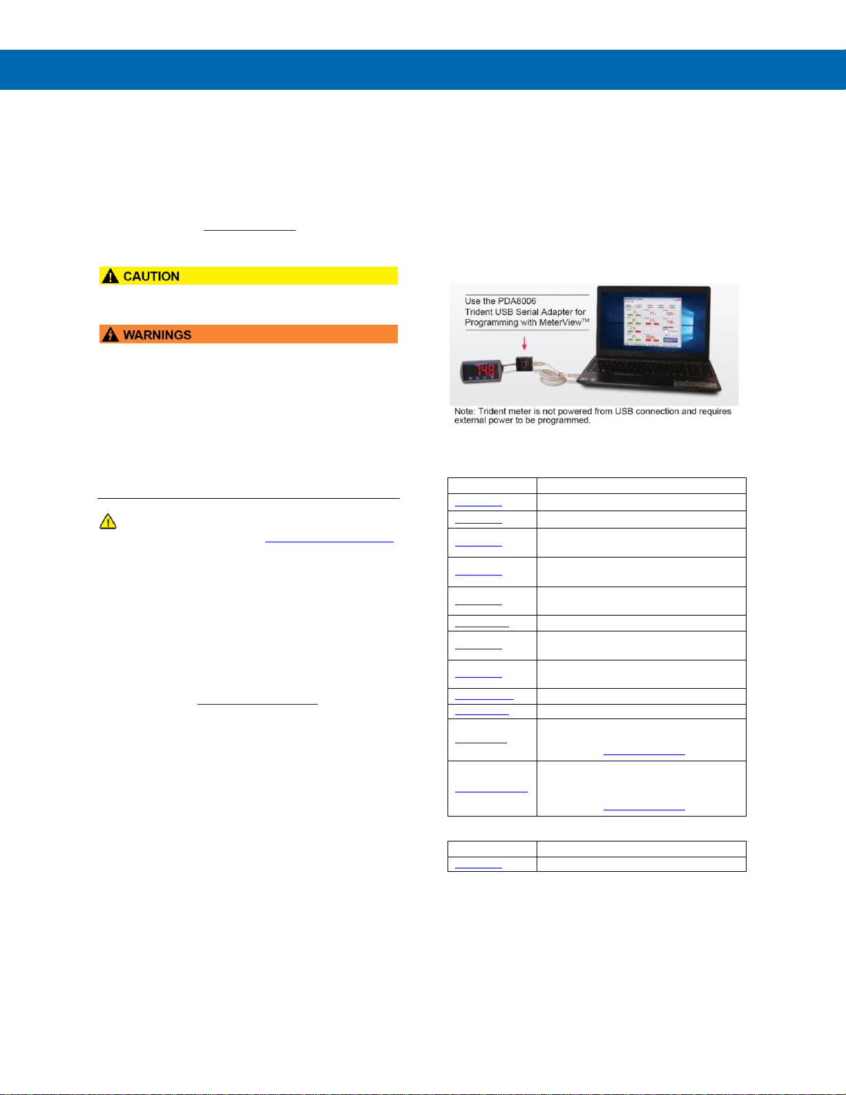
these devices is the PDA8006 USB adapter which
allows the PD765 or PD8-765 to connect to a PC
running free MeterView programming software via the
USB port as pictured below:
Ordering Information
Model
Description
PDA1232
PROVU RS-232 Adapter
PDA1485
PROVU RS-485 Adapter
PDA7232
Trident RS-232 Adapter, PDA7420
included
PDA7420
Trident Meter Copy Cable
7' (2.1 m)
PDA7422
Trident RS-485 Adapter, PDA7420
included
PDA7485-I
RS-232 to RS-485 Isolated Converter
PDA8006
Trident USB Adapter for programming
only
PDA8008
PROVU USB Adapter for programming
meter when powered from AC or DC
PDA8232-N
USB to RS-232 Non-Isolated Converter
PDA8485-I
USB to RS-485 Isolated Converter
MeterView
MeterView Software for PD765 and
PD8-765 meters. FREE download
available at www.predig.com
MeterView Pro
MeterView Pro Software for PROVU,
Helios, and ProtEX MAX meters.
Pre-loaded to meter. FREE download
available at www.predig.com.
Accessories
Model
Description
PDA1002
DIN rail mounting kit for two devices
Page 3

Serial Communication Converters & Adapters
Instruction Manual
3
Table of Contents
Introduction .......................................................................................................... 2
Ordering Information ........................................................................................... 2
Specifications....................................................................................................... 5
PDA1232 PROVU RS-232 Adapter ................................................................... 5
PDA1485 PROVU RS-485 Adapter ................................................................... 5
PDA7232 Trident RS-232 Adapter .................................................................. 5
PDA7420 Trident Meter Copy Cable .............................................................. 5
PDA7422 Trident RS-485 Adapter .................................................................. 5
PDA7485 RS-232 to RS-485 Converter............................................................ 5
PDA8006 Trident USB Adapter ....................................................................... 6
PDA8008 PROVU USB Adapter ........................................................................ 6
PDA8232 USB to RS-232 Converter ............................................................... 6
PDA8485 USB to RS-485 Converter ............................................................... 6
General (All) ..................................................................................................... 6
USB Drivers for Serial Communications Adapters ...................................... 6
DIN Rail Mounting Instructions .......................................................................... 7
Serial Communications Overview ...................................................................... 8
PDA1232 PROVU RS-232 Serial Adapter ............................................................. 9
Description ....................................................................................................... 9
Installation ........................................................................................................ 9
Connections ..................................................................................................... 9
PDA1485 PROVU RS-485 Serial Adapter ........................................................... 10
Description ..................................................................................................... 10
Installation ...................................................................................................... 10
Connections ................................................................................................... 10
PDA7232 Trident RS-232 Serial Adapter.......................................................... 11
Description ..................................................................................................... 11
Installation ...................................................................................................... 11
Connections ................................................................................................... 11
PDA7420 Trident Meter Copy Cable ................................................................. 11
Description ..................................................................................................... 11
Connections ................................................................................................... 11
Operation ........................................................................................................ 11
PDA7422 Trident RS-485 Serial Adapter.......................................................... 12
Description ..................................................................................................... 12
Installation ...................................................................................................... 12
Connections ................................................................................................... 13
PDA7485 RS-232 to RS-485 Converter............................................................. 13
Description ..................................................................................................... 13
Installation ...................................................................................................... 13
Connections ................................................................................................... 14
PDA8006 Trident to USB Serial Adapter .......................................................... 15
Description ..................................................................................................... 15
Installation ...................................................................................................... 15
USB Drivers for PDA8006 ............................................................................. 15
PDA8008 PROVU to USB Serial Adapter ........................................................... 15
Description ..................................................................................................... 15
Installation ...................................................................................................... 15
USB Drivers for PDA8008 ............................................................................. 15
PDA8232 USB to RS-232 Converter ................................................................. 16
Description ..................................................................................................... 16
Installation ...................................................................................................... 16
PDA8485 USB RS-485 Converter...................................................................... 16
Description ..................................................................................................... 16
Installation ...................................................................................................... 16
Connections ................................................................................................... 17
Troubleshooting................................................................................................. 18
Page 4

Serial Communication Converters & Adapters
Instruction Manual
4
Table of Figures
Figure 1. DIN Rail Clips Mounted to Expansion Module .................................. 7
Figure 2. Hinge & Latch End of DIN Rail Clip .................................................... 7
Figure 3. DIN Rail Clips Mounted to Module ..................................................... 7
Figure 4. Examples of Clips Mounted to Modules ............................................ 7
Figure 5. Mounting the DIN Rail with 2 #10 Pan Head Screws ........................ 7
Figure 6. Examples of Modules Mounted to DIN Rail ...................................... 7
Figure 7. Snapping the Module to the DIN Rail ................................................. 7
Figure 8. Typical Installation of DIN Rail Mounted Devices ............................. 7
Figure 9. General Four-Wire Network Connections.......................................... 8
Figure 10. General Two-Wire Network Connections ........................................ 8
Figure 11. RS-232 Adapter Connections ........................................................... 9
Figure 12. RS-422 or RS-485 Wiring ................................................................. 10
Figure 13. RS-485 Two-Wire Multi-Drop Wiring .............................................. 10
Figure 14. Connections for PDA1485 to Serial Converter.............................. 10
Figure 15. RS-232 Adapter Connections ......................................................... 11
Figure 16. Standard Modular Cable Wiring ..................................................... 11
Figure 17. Trident Copy Cable Connecting Two Meters ................................ 11
Figure 18. RS-422 or RS-485 Wiring ................................................................. 12
Figure 19. RS-485 Two-Wire Multi-Drop Wiring .............................................. 12
Figure 20. Standard Modular Cable Wiring ..................................................... 13
Figure 21. Connections for PDA7422 to Serial Converter.............................. 13
Figure 22. PDA7485 Connections and DIP Switch Settings .......................... 13
Figure 23. PDA7485 DIP Switch Settings Chart .............................................. 14
Figure 24. PDA7485 RS-485 Two-Wire Multi-Drop Wiring .............................. 14
Figure 25. Connections for PDA7485 in a Four-Wire Network ...................... 14
Figure 26. Connections for PDA7485 in a Two-Wire Network ....................... 14
Figure 27. Trident USB Adapter Connections ................................................. 15
Figure 28. PROVU USB Adapter Connections .................................................. 15
Figure 29. Connections for PDA8232 to serial device .................................... 16
Figure 30. PDA8485 DIP Switch Location ........................................................ 16
Figure 31. PDA8485 DIP Switch Settings......................................................... 17
Figure 32. Connections for PDA8485 in a Four-Wire Network ...................... 17
Figure 33. Connections for PDA8485 in a Two-Wire Network ....................... 17
Figure 34. PDA8485 RS-485 Two-Wire Multi-Drop Wiring .............................. 17
Page 5

Serial Communication Converters & Adapters
Instruction Manual
5
Specifications
PDA1232 PROVU RS-232 Adapter
Compatibility
EIA-232
Connectors
PC compatible 9-pin D subminiature
connector (DB9) and RJ45 (adapter to
meter)
Cable
6' (1.8 m) standard Cat5e cable
provided with adapter
Dimension
1.7" x 0.9" x 2.7"
(43 mm x 24 mm x 70 mm)
(W x H x D)
Distance
Adapter to:
PROVU meter: 6' (1.8 m) max;
Computer: 50' (15 m) max;
Serial interface cable not provided
Power
Powered by PROVU meter M-Link
connection
Status Indication
Separate LEDs for Power (P)
Transmit (TX), and Receive (RX).
PDA1485 PROVU RS-485 Adapter
Compatibility
EIA-485
Connectors
Removable screw terminal connector
and RJ11 (adapter to meter)
Cable
6' (1.8 m) standard Cat5e cable
provided with adapter
Dimension
1.7" x 0.9" x 3.0"
(43 mm x 24 mm x 76 mm)
(W x H x D)
Distance
Adapter to:
PROVU meter: 6' (1.8 m) max;
Computer: 3,937' (1,200 m) max
Power
Powered by PROVU meter M-Link
connection
Status Indication
Separate LEDs for Power (P),
Transmit (TX), and Receive (RX)
PDA7232 Trident RS-232 Adapter
Compatibility
EIA-232
Connectors
PC compatible 9-pin D subminiature
connector (DB9) and RJ11 (adapter to
meter)
Cable
7' (2.1 m) standard modular cable
provided with adapter
Dimension
1.7" x 0.9" x 2.7"
(43 mm x 24 mm x 70 mm)
(W x H x D)
Distance
Adapter to:
PD765 meter: 7' (2.1 m) max;
Computer: 50' (15 m) max;
Serial interface cable not provided
Power
Powered by Trident PD765 RJ11
connection
Status Indication
Separate LEDs for Power (P),
Transmit (TX), and Receive (RX)
PDA7420 Trident Meter Copy Cable
Purpose
To clone programming from one
Trident meter to another
Connectors
RJ11
Cable
One 7' (2.1 m) standard modular cable
PDA7422 Trident RS-485 Adapter
Compatibility
EIA-485
Connectors
Removable screw terminal connector
and RJ11 (adapter to meter)
Cable
7' (2.1 m) standard modular cable
provided with adapter
Dimension
1.7" x 0.9" x 3.0"
(43 mm x 24 mm x 76 mm)
(W x H x D)
Distance
Adapter to:
PD765 meter: 7' (2.1 m) max;
Computer: 3,937' (1,200 m) max
Power
Powered by Trident PD765 RJ11
connection
Status Indication
Separate LEDs for Power (P),
Transmit (TX), and Receive (RX)
PDA7485 RS-232 to RS-485 Converter
Compatibility
EIA-232, EIA-422, and EIA-485
Connectors
Screw terminal connector and DB9
Dimension
1.7" x 0.9" x 3.3"
(43 mm x 24 mm x 83 mm)
(W x H x D)
Distance
RS-232 connection: 50' (15 m) max;
RS-485 connection:
3,937' (1,200 m) max
Number of Units
Up to 31 RS-485 compatible devices
Power
9-12 VDC; 115 VAC/12 VDC adapter
included
Status Indication
Separate LEDs for Power (P),
Transmit (TX), and Receive (RX)
Isolation
1500 VAC between data lines;
700 VDC input/output-to-power
Page 6

Serial Communication Converters & Adapters
Instruction Manual
6
PDA8006 Trident USB Adapter
Purpose
To be used only for programming the
Trident meter
Compatibility
USB 1.1, USB 2.0
Connectors
RJ11, and USB Type B
Cable
One 7' (2.1 m) standard modular cable
and one 3.28' (1.0 m) USB A-B Male
cable provided with adapter
Dimension
1.7" x 0.8" x 3.3"
43 mm x 21 mm x 83 mm)
(W x H x D)
Distance
Adapter to:
PD765/PD8-765 meter: 7' (2.1 m) max;
USB connection to PC: 10' (3 m) max
Driver
Compatibility
Win 98/2000/ME/XP/Vista/7/8/10
Power
USB Port
Status Indication
Separate LEDs for Power (P),
Transmit (TX), and Receive (RX)
PDA8008 PROVU USB Adapter
Purpose
Programming (only) PROVU meter
when meter powered from AC or DC.
Compatibility
USB 1.1, USB 2.0
Connectors
RJ45, and USB Type B
Cable
One 6' (1.8 m) standard Cat5e cable
and one 3.28' (1.0 m) USB A-B Male
cable provided with adapter
Dimension
1.7" x 0.8" x 3.3"
43 mm x 21 mm x 83 mm)
(W x H x D)
Distance
Adapter to:
PROVU meter: 6' (1.8 m) max.
USB connection: 10' (3 m) max
Driver
Compatibility
Win 98/2000/ME/XP/Vista/7/8/10
Power
USB Port
Status Indication
Separate LEDs for Power (P),
Transmit (TX), and Receive (RX)
PDA8232 USB to RS-232 Converter
Compatibility
USB 1.1, USB 2.0, EIA-232
Connectors
PC compatible 9-pin D subminiature
connector (DB9) and USB Type A
Dimension
3' (91.44 cm) (Length)
Distance
USB connection: 10' (3 m) max;
RS-232 connection: 50' (15m) max
Driver
Compatibility
Win 98/2000/ME/XP/Vista/7/8/10
Power
USB port
PDA8485 USB to RS-485 Converter
Compatibility
USB 1.1, USB 2.0, EIA-422, and
EIA-485
Connectors
Screw terminal connector and USB
Type B
Dimension
1.7" x 0.9" x 3.0"
(43 mm x 24 mm x 76 mm)
(W x H x D)
Distance
USB connection: 10' (3 m) max;
RS-485 connection:
3,937' (1,200 m) max
Driver
Compatibility
Win 98/2000/ME/XP/Vista/7/8/10
Number of Units
Up to 31 RS-485 compatible devices
Power
USB Port
Status Indication
Separate LEDs for Power (P),
Transmit (TX), and Receive (RX)
Isolation
1500 VAC between data lines;
700 VDC input/output-to-power
General (All)
Warranty
1 year parts & labor. See Warranty
Information and Terms & Conditions on
www.predig.com for complete details.
USB Drivers for Serial Communications Adapters
USB Drivers for serial communications adapters are
available for download at:
Software Downloads
Page 7
Serial Communication Converters & Adapters
Instruction Manual
7
DIN Rail Mounting Instructions
The following instructions for expansion modules may be used
for mounting the converters and adapters to DIN rails.
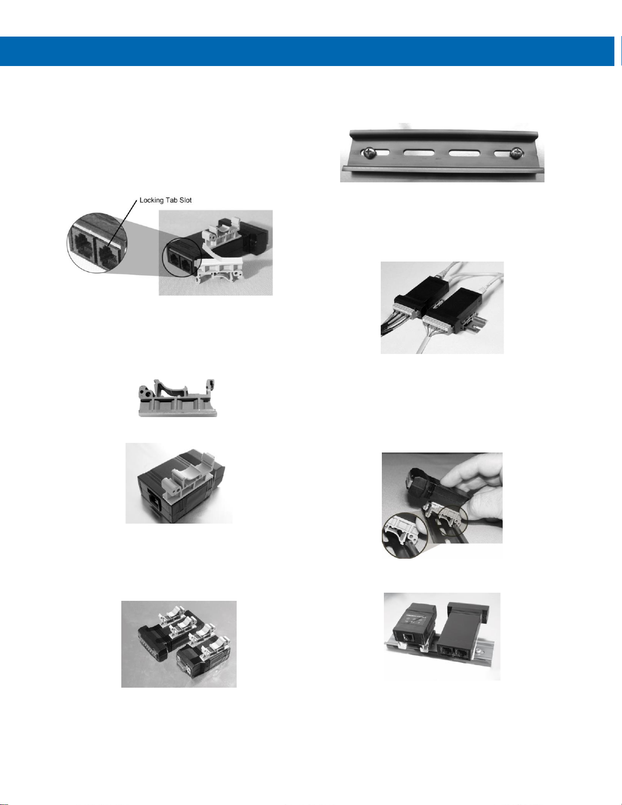
Step 1: Mounting the DIN Rail Clips to Module
Place the expansion module on a flat surface with the bottom
surface facing up. The bottom surface can be identified as the
surface closest to the locking tab slot on the modular
connector as shown in Figure 1.
Figure 1. DIN Rail Clips Mounted to Expansion Module
Peel the protective layer off the adhesive tape on the bottom of
one of the mounting clips. With the hinge end of the clip, as
shown in Figure 2, facing the end of the module with the
communications connector, align the clip along the long (side)
edge of the module and centered lengthwise within the flat
surface of the module as shown in Figure 3.
Figure 2. Hinge & Latch End of DIN Rail Clip
Figure 3. DIN Rail Clips Mounted to Module
Firmly press down on the clip for 10 seconds. Repeat this
procedure on the opposite side. Once the clips are properly
installed, the modules with clips mounted should look similar to
one or both of the modules pictured in Figure 4. While the
adhesive is initially quite strong, this strength improves
significantly over a period of approximately 12 hours.
Figure 4. Examples of Clips Mounted to Modules
Step 2: Mounting the DIN Rail to a Surface
The expansion modules, serial adapters and serial converters
weigh approximately 1.5 oz (42 grams) each so the mounting
hardware does not need to be overly strong. We recommend
two #10 pan head screws as shown in Figure 5, but only
because they best accommodate the slots in the DIN rail. The
amount of strain the wiring might place on the module
mounting needs to be considered also. In many cases, DIN rail
with double-sided tape might be acceptable, although not
recommended in areas of high vibration or extreme hot or cold
temperatures.
Figure 5. Mounting the DIN Rail with 2 #10 Pan Head Screws
When choosing a location to mount the DIN rail, keep in mind
that wires will be entering both ends of the modules as shown
in Figure 6. Leave enough room on either end of module to
allow for wire routing to prevent undue stress placed on the
module’s connectors and mounting clips. The DIN rail may be
mounted on any vertical or horizontal mounting surface.
Figure 6. Examples of Modules Mounted to
DIN Rail
Step 3: Mounting Modules to the DIN Rail
To mount modules to a DIN rail, first locate the approximate
desired position to place the module on the DIN rail, then hook
the hinge end of the mounting clip to the edge of the DIN rail
as shown in Figure 7. Next lower the opposite “latch end” of
the clip onto the rail. Press down on the module until the latch
end snaps in place.
Figure 7. Snapping the Module to the DIN Rail
A typical installation will look like Figure 8 once modules are
mounted to the DIN rail.
Figure 8. Typical Installation of DIN Rail Mounted Devices
Step 4: Connections
After mounting the device(s), refer to the Instruction Manual for
each module for proper connections and operation.
Hinge End Latch End
Page 8
Serial Communication Converters & Adapters
Instruction Manual
8
Serial Communications Overview
RS-232 and RS-485 are standard interfaces approved
by the Electronic Industries Alliance (EIA) for
connecting serial devices. In EIA terms, the device (e.g.
meter) that connects to the interface is called a Data
Communications Equipment (DCE) and the device to
which it connects (e.g. the computer) is called a Data
Terminal Equipment (DTE).
The RS-422 standard was designed to replace the older
RS-232 standard because it supports higher data rates
and greater immunity to electrical interference. RS-485
is similar to RS-422 but can support multi-point
connections per line because it uses lower-impedance
drivers and receivers.
Line drivers and receivers are used to exchange data
between two or more points (nodes) on a serial
communications network. Reliable data
communications can be difficult in the presence of
induced noise, ground level differences, and other
hazards associated with installation of a network. When
communicating at high data rates, or over long
distances in real world environments, RS-232 is often
inadequate. The differential data transmission of RS422 and RS-485 offers superior performance in most
applications. Differential signals can help nullify the
effects of ground shifts and induced noise signals that
can appear as common mode voltages on a network.
RS-422 was designed for greater distances and higher
baud rates than RS-232. In its simplest form, a pair of
converters from RS-232 to RS-422 (and back again)
can be used to form an “RS-232 extension cord”. Data
rates of up to 100 kbits/second and distances of 3,937'
(1,200 m) can be accommodated with RS-422.
RS-422 devices however cannot be used to construct a
true multi-point network. A multi-point network consists
of multiple drivers and receivers connected on a single
bus, where any point (node) can transmit and/or receive
data. RS-485 is an enhanced version of the RS-422
standard, which allows multiple drivers and receivers on
the same two-wire or four-wire system. The RS-485
standard specifies up to 32 drivers and 32 receivers on
a single bus, but with the introduction of “automatic”
repeaters and high-impedance drivers/receivers, this
number can be extended to hundreds of points (nodes)
on a network.
The cabling used for an RS-422 or RS-485 serial
communications network should always be a highquality cable such as Belden 8162 or Alpha 6203C.
A two-wire system requires two twisted pairs, and a
four-wire system requires three twisted pairs (the extra
twisted pair is needed for the signal ground).
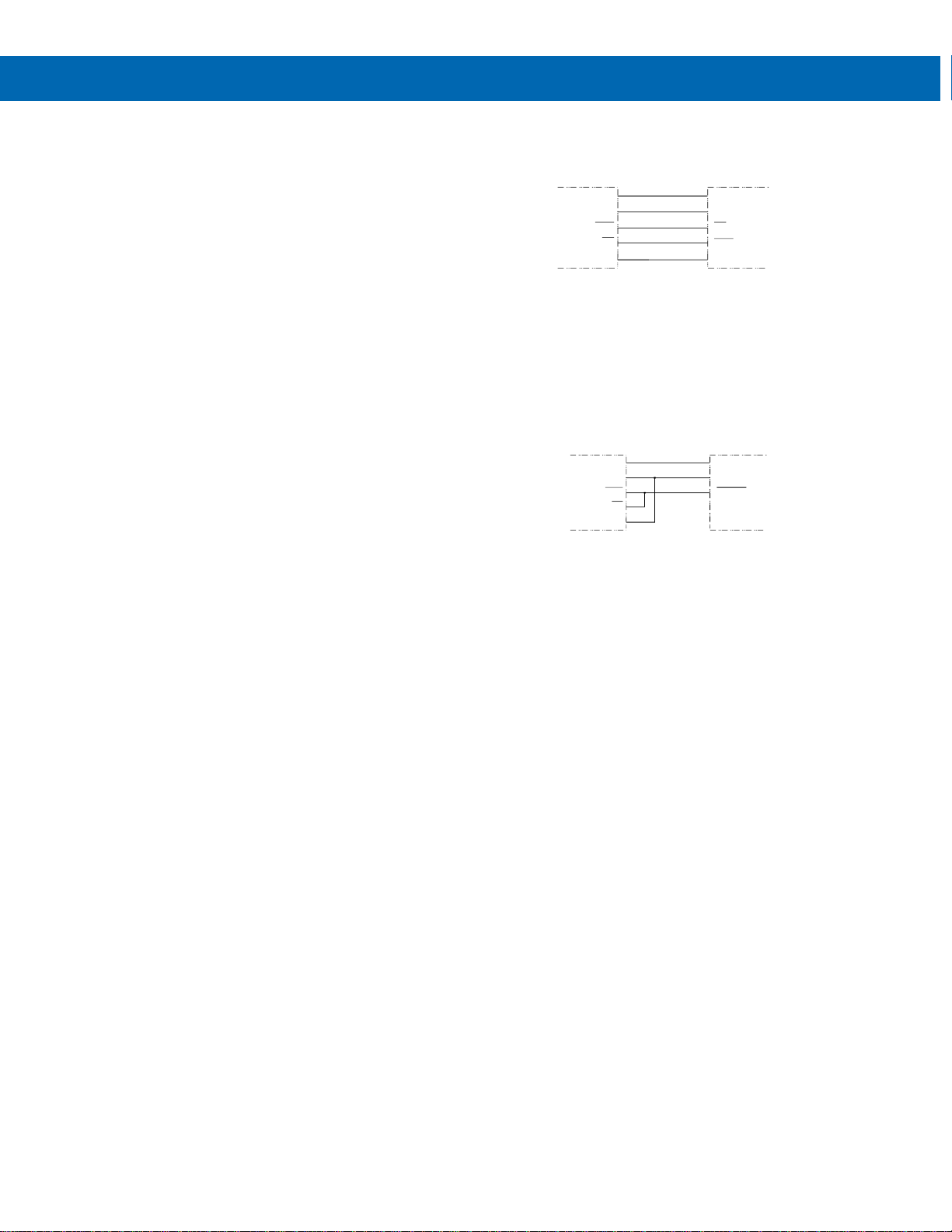
Figure 9 illustrates how to connect a general four-wire
network (a four-wire network actually contains 5 wires).
Figure 9. General Four-Wire Network Connections
Figure 10 illustrates how to connect a general two-wire
network (a two-wire network actually contains 3 wires).
Note that the PDA7485 and PDA8485 have DIP
switches that allow for two-wire connections without the
need to externally wire the DO to the DI and the /DO to
the /DI (see the converter section for complete details).
Figure 10. General Two-Wire Network Connections
PDA8485
DO
DO
DI
DI
GND GND
RS-422/485 DEVICE
DI
DI
DO
DO
PDA8485
DO
DO
DI
DI
GND GND
RS-485 DEVICE
DATA
DATA
Page 9
Serial Communication Converters & Adapters
Instruction Manual
9
PDA1232 PROVU RS-232 Serial Adapter
Description
The PDA1232 converts the serial output of the PROVU
meter to an unbalanced, full-duplex RS-232 signal.
The RS-232 port has a female DB9 connector with pins
2 (RX output), 3 (TX input), and 5 (Signal Ground). Pins
7 (RTS) and 8 (CTS) are tied together, and pins 1 (CD),
4 (DTR), and 6 (DSR) are tied together. The adapter is
powered by the PROVU meter M-Link connection.
Baud rates are adjustable and handled by the PROVU
(see the PROVU Instruction Manual for more details).
The PDA1232 has three diagnostic LEDs: a Power (P)
LED to show when the adapter is powered properly, a
Transmit Data (TX) LED to show when the adapter is
sending data out from the PC side, and a Receive Data
(RX) LED to show when the adapter is receiving data
from the PROVU meter.
Installation
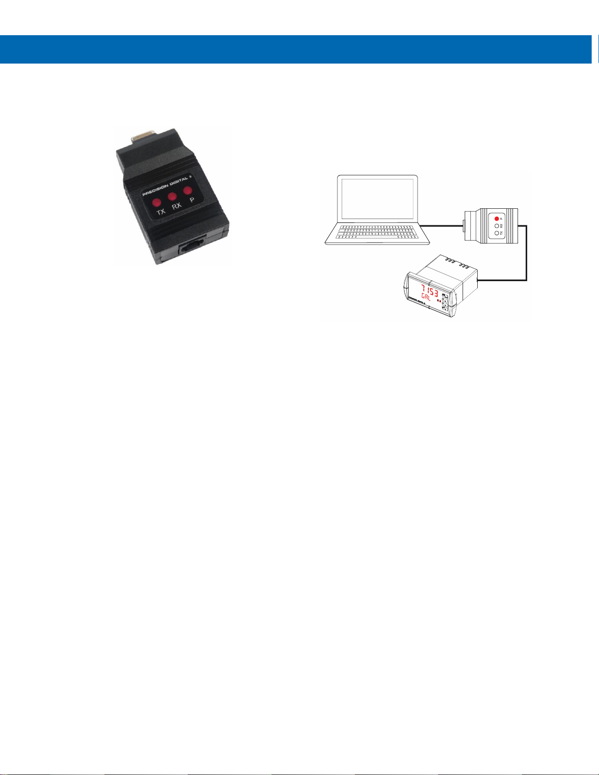
Figure 11 shows the connection of a PROVU meter to a
PC using the PDA1232 serial adapter. The PDA1232
has an RJ45 connector to connect the Cat5e cable and
a PC compatible 9-pin D subminiature connector (DB9).
The DB9 can be connected directly to the PC or by
using a standard serial extension cable.
Figure 11. RS-232 Adapter Connections
Connections
A Cat5e cable is provided to connect the PROVU meter
to the PDA1232 serial adapter.
Serial Cable
(Not Provided)
RS-232 Adapter
Cat5e Cable
(Provided)
Page 10
Serial Communication Converters & Adapters
Instruction Manual
10
PDA1485 PROVU RS-485 Serial Adapter
Description
The PDA1485 converts the serial output of the PROVU
meter to balanced, full or half-duplex RS-485 signals.
The PDA1485 has a removable screw terminal
connector for the RS-485 terminals which includes
Transmit Data (DO) and (/DO), Receive Data (DI) and
(/DI), and Signal Ground. The adapter is provided by
the PROVU meter M-Link connection.
Baud rates are adjustable and handled by the PROVU
(see the PROVU Instruction Manual for more details).
The PDA1485 has three diagnostic LEDs: a Power (P)
LED to show when the adapter is powered properly, a
Transmit Data (TX) LED to show when the adapter is
sending data out from the PC side, and a Receive Data
(RX) LED to show when the adapter is receiving data
from the PROVU meter.
Installation
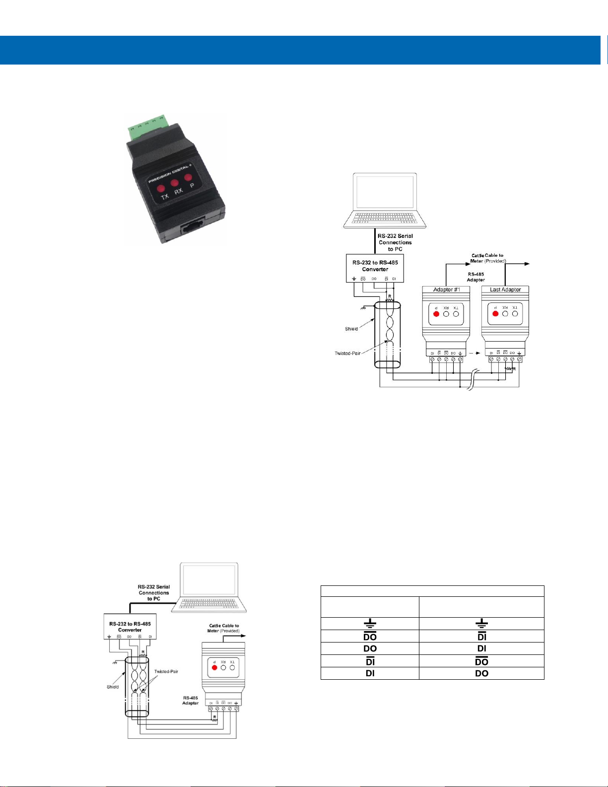
Figure 12 shows the connection of a PROVU meter to a
PC using the PDA1485 serial adapter and a PDA7485
RS-232 to RS-485 converter in an RS-422 network. The
PDA1485 has an RJ45 connector to connect the Cat5e
cable and a screw terminal connector to connect to the
RS-422 network.
Figure 13 shows the connection of PROVU meters with
PDA1485 serial adapters to a PC using a PDA7485
RS-232 to RS-485 converter in an RS-485 network.
Figure 12. RS-422 or RS-485 Wiring
Notes:
1. Termination resistors are optional and values
depend on the cable length and characteristic
impedance. Consult the cable manufacturer for
recommendations.
2. Refer to PDA7485 RS-232 to RS-485
Converter on page 13 for further details.
3. Use shielded cable, twisted-pairs plus ground.
Connect ground shield only at one location.
Figure 13. RS-485 Two-Wire Multi-Drop Wiring
Notes:
1. Termination resistors are optional and values
depend on the cable length and characteristic
impedance. Consult the cable manufacturer for
recommendations.
2. Refer to PDA7485 RS-232 to RS-485
Converter on page 13 for further details.
3. Use shielded cable, twisted-pair plus ground.
Connect ground shield only at one location.
Connections
A Cat5e cable is provided to connect the PROVU meter
to the PDA1485 adapter.
Figure 14 details the wiring connections from the
PDA1485 to an RS-485 serial converter (such as the
PDA7485 or PDA8485) for a four-wire network.
PDA1485 to RS-485 Serial Converter Connections
RS-485 Serial
Converter
PDA1485 RS-485 Adapter
Figure 14. Connections for PDA1485 to Serial Converter
If the serial converter is configured for a two-wire
network, then the requirement to externally wire the DO
to the DI and the /DO to the /DI on the PDA1485 screw
terminal connector is needed.
Page 11
Serial Communication Converters & Adapters
Instruction Manual
11
PDA7232 Trident RS-232 Serial Adapter
Description
The PDA7232 converts the serial output of the PD765
Trident meter to an unbalanced, full-duplex RS-232
signal.
The RS-232 port has a female DB9 connector with pins
2 (RX output), 3 (TX input), and 5 (Signal Ground). Pins
7 (RTS) and 8 (CTS) are tied together, and pins 1 (CD),
4 (DTR), and 6 (DSR) are tied together. The adapter is
powered by the PD765 Trident meter.
Baud rates are adjustable and handled by the PD765
(see the Trident Instruction Manual for more details).
The PDA7232 has three diagnostic LEDs: a Power (P)
LED to show when the adapter is powered properly, a
Transmit Data (TX) LED to show when the adapter is
sending data out from the PC side, and a Receive Data
(RX) LED to show when the adapter is receiving data
from the Trident PD765 meter.
Installation
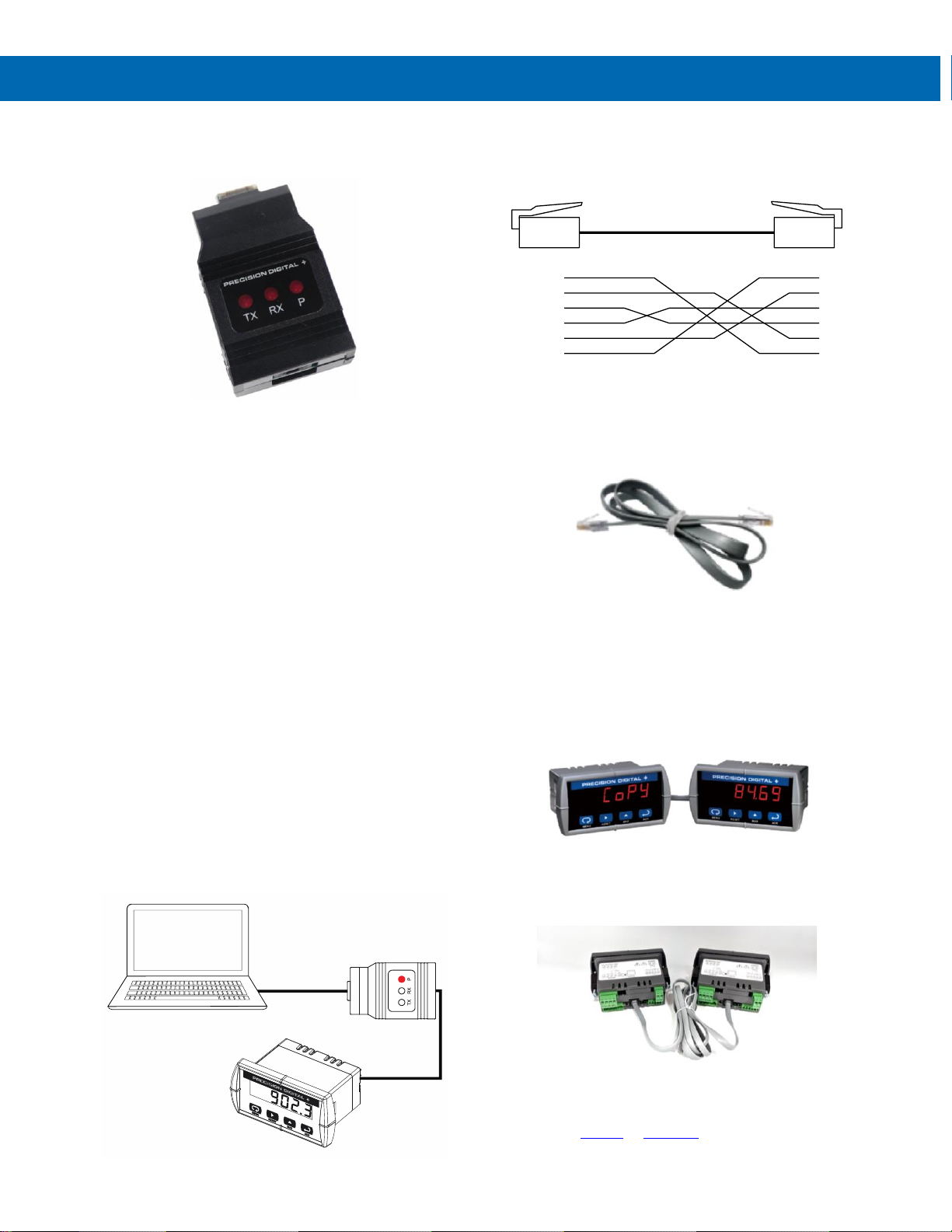
Figure 15 shows the connection of a Trident meter to a
PC using the PDA7232 serial adapter. The PDA7232
has an RJ11 connector to connect the PDA7420
modular cable and a PC compatible 9-pin D
subminiature connector (DB9). The DB9 can be
connected directly to the PC or by using a standard
serial extension cable.
Figure 15. RS-232 Adapter Connections
Connections
A PDA7420 cable is provided to connect the Trident
meter to the PDA7232 serial adapter. Figure 16 shows
the PDA7420 cable details.
Figure 16. Standard Modular Cable Wiring
PDA7420 Trident Meter Copy Cable
Description
The PDA7420 Trident Meter Copy Cable is used to
copy (or clone) all the settings from one Trident meter
to other Trident meters requiring exactly the same setup
and programming (i.e. type of input, scaling, decimal
point, filter, bypass, etc.). The Copy operation can be
completed in less than 10 seconds. The Copy function
is a standard feature on all Trident meters.
Connections
Connect the two ends of the PDA7420 as shown in
Figure 17.
Figure 17. Trident Copy Cable Connecting Two Meters
Operation
Refer to the PD765 or PD8-765 manual for instructions
on how to perform the Copy function.
Serial Cable
(Not Provided)
RS-232 Adapter
Modular Cable
(Provided)
(WH) 1
(BK) 2
(R) 3
(G) 4
(Y) 5
(BL) 6
1
2
3
4
5
6
Page 12
Serial Communication Converters & Adapters
Instruction Manual
12
PDA7422 Trident RS-485 Serial Adapter
Description
The PDA7422 converts the serial output of the PD765
Trident meter to balanced, full or half-duplex RS-485
signals.
The PD7422 has a removable screw terminal connector
for the 485 terminals which includes Transmit Data
(DO) and (/DO), Receive Data (DI) and (/DI), and Signal
Ground.
Baud rates are adjustable and handled by the PD765
(see the Trident Instruction Manual for more details).
The PDA7422 has three diagnostic LEDs: a Power (P)
LED to show when the adapter is powered properly, a
Transmit Data (TX) LED to show when the adapter is
sending data out from the PC side, and a Receive Data
(RX) LED to show when the adapter is receiving data
from the Trident PD765 meter.
Installation
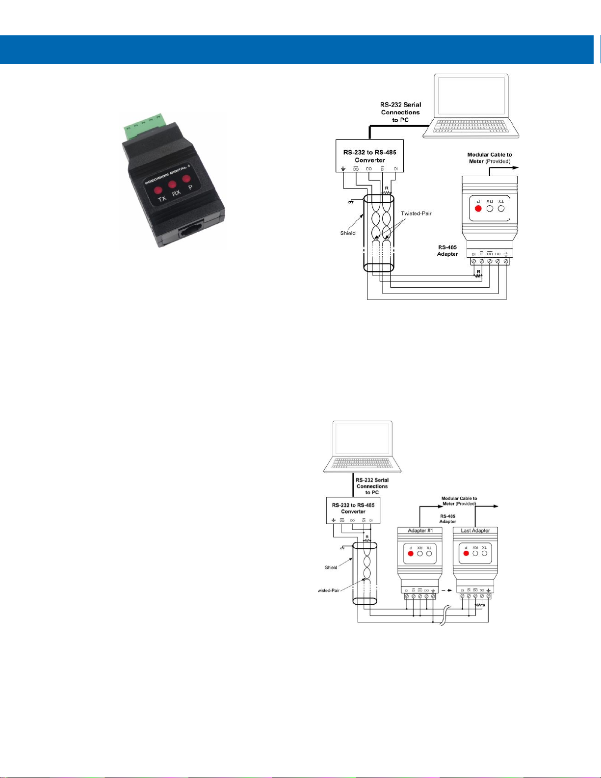
Figure 18 shows the connection of a Trident meter to a
PC using the PDA7422 serial adapter and a PDA7485
RS-232 to RS-485 converter in an RS-422 network. The
PDA7422 has an RJ11 connector to connect the
PDA7420 modular cable and a screw terminal
connector to connect to the RS-422 network. shows the
connection of several Trident meters with PDA7422
serial adapters to a PC using a PDA7485 RS-232 to
RS-485 converter in an RS-485 network.
Figure 18. RS-422 or RS-485 Wiring
Notes:
1. Termination resistors are optional and values
depend on the cable length and characteristic
impedance. Consult the cable manufacturer for
recommendations.
2. Refer to PDA7485 RS-232 to RS-485
Converter on page 13 for further details.
3. Use shielded cable, twisted-pairs plus ground.
Connect ground shield only at one location.
Figure 19. RS-485 Two-Wire Multi-Drop Wiring
Notes:
1. Termination resistors are optional and values
depend on the cable length and characteristic
impedance. Consult the cable manufacturer for
recommendations.
2. Refer to PDA7485 RS-232 to RS-485
Converter on page 13 for further details.
3. Use shielded cable, twisted-pair plus ground.
Connect ground shield only at one location.
Page 13
Serial Communication Converters & Adapters
Instruction Manual
13
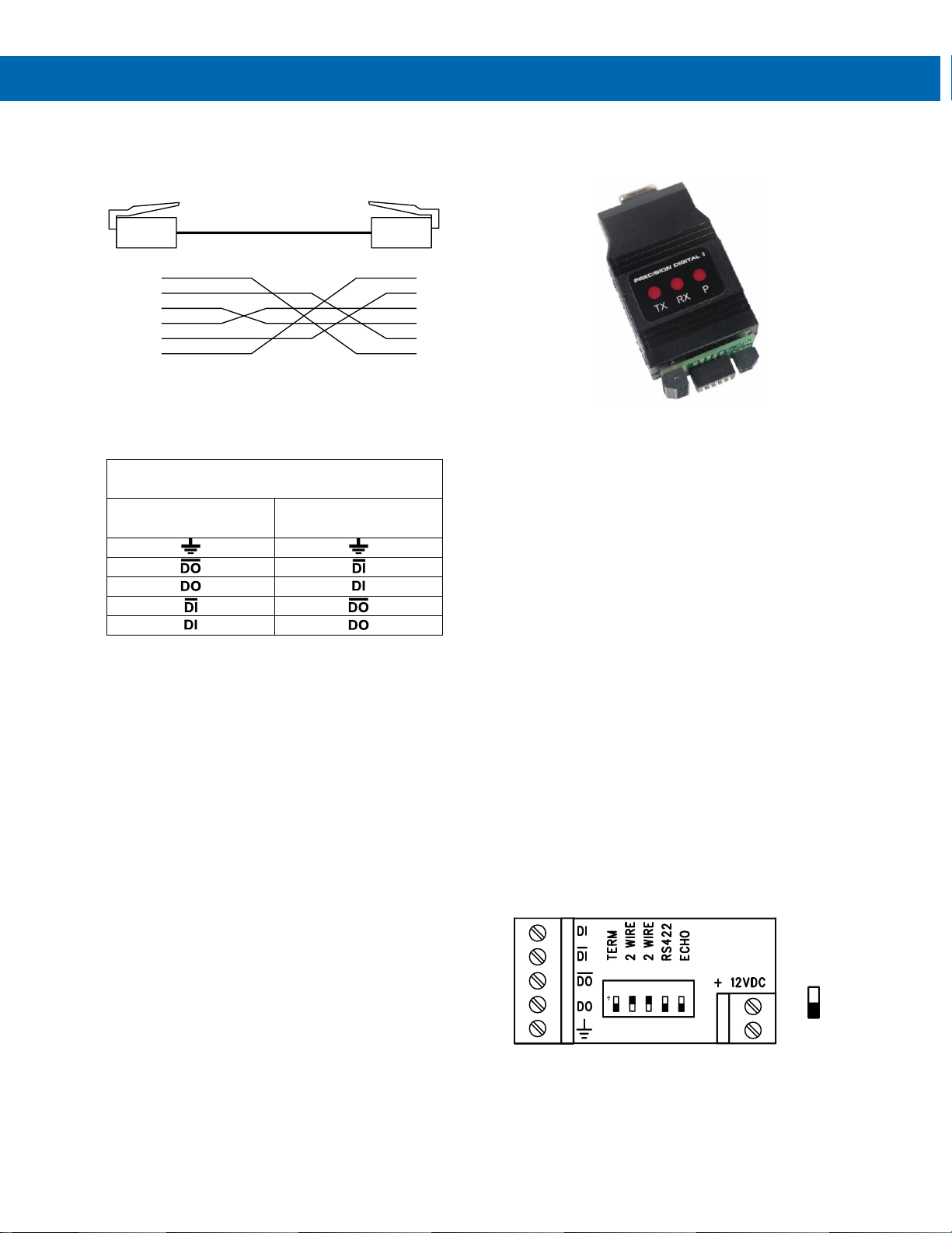
Connections
A PDA7420 cable is provided to connect the Trident
meter to the PDA7422 adapter. Figure 20 shows the
PDA7420 cable details.
Figure 20. Standard Modular Cable Wiring
Figure 21 details the wiring connections from the
PDA7422 to an RS-485 serial converter (such as the
PDA7485 or PDA8485) for a four-wire network.
PDA7422 to RS-485 Serial Converter
Connections
RS-485 Serial
Converter
PDA7422
RS-485 Adapter
Figure 21. Connections for PDA7422 to Serial Converter
If the serial converter is configured for a two-wire
network then the requirement to externally wire the DO
to the DI and the /DO to the /DI on the PDA7422 screw
terminal connector is needed.
PDA7485 RS-232 to RS-485 Converter
Description
The PDA7485 converts unbalanced, full-duplex RS-232
signals to balanced, full or half-duplex RS-422 or
RS-485 signals.
The RS-232 port, configured as a DTE port, has a
female DB9 connector with pins 2 (RX output),
3 (TX input), and 5 (Signal Ground). Pins 7 (RTS) and
8 (CTS) are tied together, and pins 1 (CD), 4 (DTR),
and 6 (DSR) are tied together. The RS-485 terminal
blocks support Transmit Data (DO) and (/DO), Receive
Data (DI) and (/DI), and Signal Ground. A separate
terminal block supports the power input (+12VDC) and
power ground (GND).
Baud rates are automatic and handled by the PDA7485.
The PDA7485 has three diagnostic LEDs: a Power (P)
LED to show when the converter is powered properly, a
Transmit Data (TX) LED to show when the converter is
sending data out from the PC side, and a Receive Data
(RX) LED to show when the converter is receiving data
from the network side.
The DIP switch SW1 is located between the screw
terminal connectors and allows for system
configurations.
Installation
The DIP switch SW1 allows for several different
options. Factory settings for the switch are shown in
Figure 22.
Figure 22. PDA7485 Connections and DIP Switch Settings
The TERM switch position adds an internal 120 ohm
termination resistor when ON (up). Termination should
be used on both ends of the network with high data
rates and long wiring runs.
(WH) 1
(BK) 2
(R) 3
(G) 4
(Y) 5
(BL) 6
1
2
3
4
5
6
1 2
3
4 5
ON
GND
SW1
Switch in
ON/UP
Position
Page 14
Serial Communication Converters & Adapters
Instruction Manual
14
To configure a two-wire network set both of the 2 WIRE
switch positions to ON (up). For a four-wire network set
both of the 2 WIRE switches to OFF (down).
When the RS-422 switch position is ON (up) it is
configured for an RS-422 network. For RS-485
networks set the RS-422 switch to OFF (down).
The ECHO switch position allows the data being sent
from the RS-232 port to be echoed back into the
RS-232 port. In most networks, this is an undesired
effect and the ECHO switch would be OFF (down).
PDA7485 DIP Switch Settings
SW1 Switch Position
ON Setting Function
1
Network Termination
Included (120 ohm)
2
2-Wire Network Mode
Connection (factory
setting)
3
2-Wire Network Mode
Connection (factory
setting)
4
RS-422 Mode
5
ECHO Mode
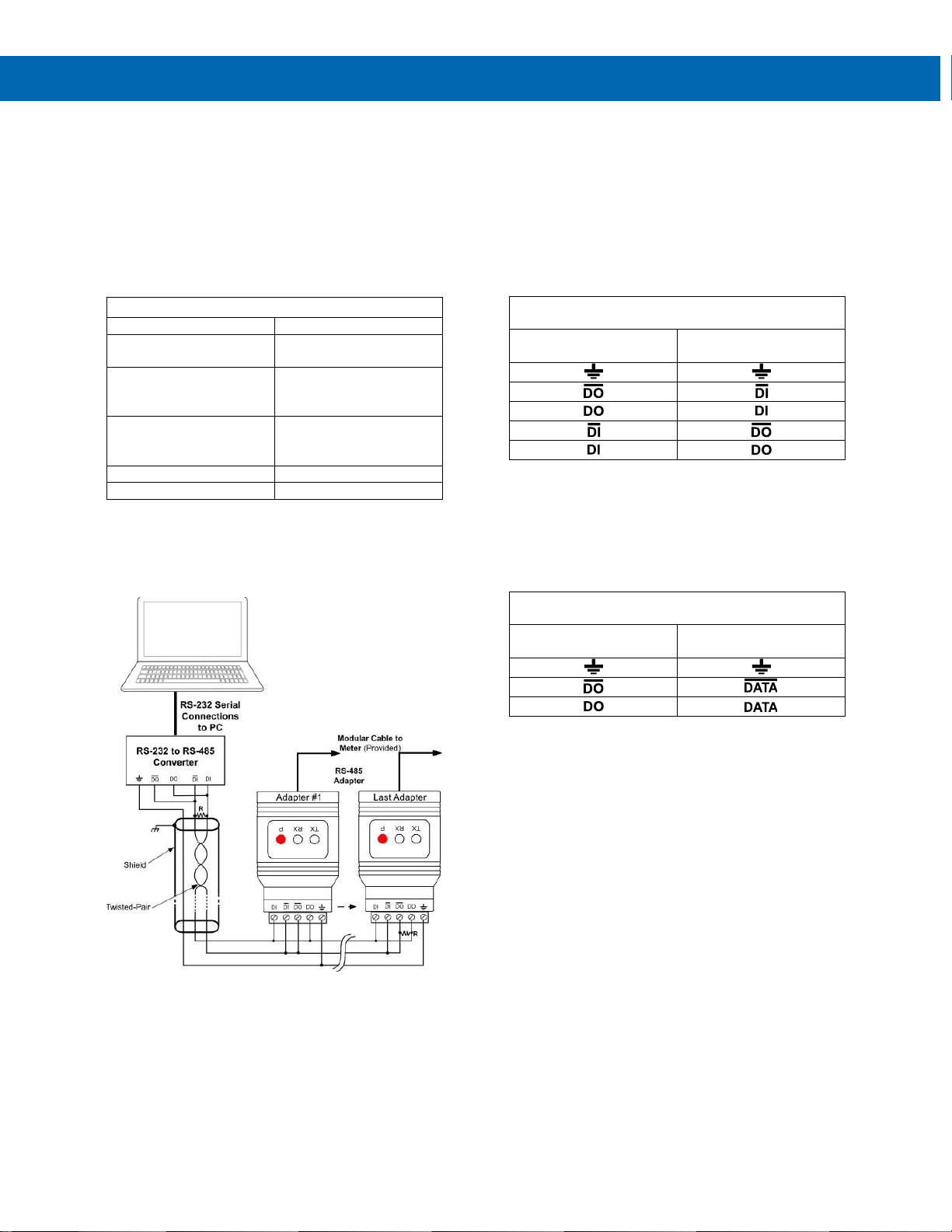
Figure 23. PDA7485 DIP Switch Settings Chart
Figure 24 shows an example configuration of a two-wire
network. Each device (e.g. Trident PD765 meter)
connected to the same network must have a unique
address.
Figure 24. PDA7485 RS-485 Two-Wire Multi-Drop Wiring
Notes:
1. Termination resistors are optional and values
depend on the cable length and characteristic
impedance. Consult the cable manufacturer for
recommendations.
2. Refer to PDA7422 Trident RS-485 Serial
Adapter on page 12 for further details.
3. Use shielded cable, twisted-pair plus ground.
Connect ground shield only at one location.
Connections
To power the PDA7485, connect 12 VDC to the
+12VDC and ground to the GND screw terminals from
the supplied 115 VAC/12 VDC adapter.
The PDA7485 may be configured for either a four-wire
or two-wire network. Figure 25 details the wiring
connections from the PDA7485 to an RS-485 serial
device in a four-wire network.
PDA7485 to RS-485 Serial Device Four-Wire
Connections
PDA7485 Serial
Converter
RS-485 Serial Device
Figure 25. Connections for PDA7485 in a Four-Wire
Network
Figure 26 details the wiring connections from the
PDA7485 to an RS-485 serial device in a two-wire
network when the DIP switches on the PDA7485 have
been set to the “2-Wire Mode”.
PDA7485 to RS-485 Serial Device Two-Wire
Connections
PDA7485 Serial
Converter
RS-485 Serial Device
Figure 26. Connections for PDA7485 in a Two-Wire
Network
The PDA7485 internally connects the /DI to the /DO and
the DI to the DO when the DIP switches are set to “2-
Wire Mode”. Either the /DI or /DO could be used to
connect to /DATA and either the DI or DO could be used
to connect to DATA.
Two PDA7485 RS-232 to RS-485 Serial Converters
could be used as a serial extender to allow RS-232
serial devices to communicate over long distances.
This would allow an RS-232 device to operate up to
3,937' (1,200 m).
Page 15
Serial Communication Converters & Adapters
Instruction Manual
15
PDA8006 Trident to USB Serial Adapter
Description
The PDA8006 Trident to USB Serial Adapter allows for
direct connection of a Trident meter to the USB port of a
PC. It is intended only for programming the meter.
Installation
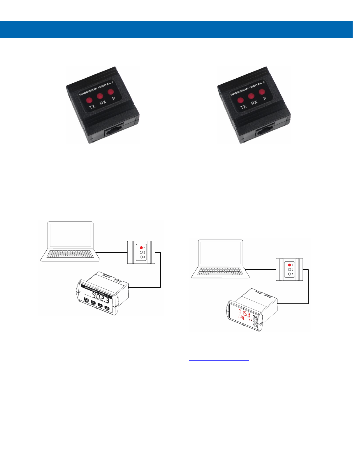
Figure 27 shows the connection of a Trident Series
meter to a PC using a PDA8006 Trident to USB Serial
Adapter.
Figure 27. Trident USB Adapter Connections
Driver Download here:
USB Drivers for PDA8006
PDA8008 PROVU to USB Serial Adapter
Description
The PDA8008 PROVU to USB Serial Adapter allows for
direct connection of a PROVU Series meter to the USB
port of a PC. It is intended only for programming the
meter when the meter is powered from AC or DC.
Otherwise the USB cable provided with the meter can
be used.
Installation
Figure 28 shows the connection of a PROVU Series
meter to a PC using a PDA8008 PROVU to USB Serial
Adapter.
Figure 28. PROVU USB Adapter Connections
Driver Download here:
USB Drivers for PDA8008
USB Cable
(Provided)
USB Serial
Adapter
Standard
Modular Cable
(Provided)
USB Cable
(Provided)
USB Serial
Adapter
Cat5e Cable
(Provided)
Page 16
Serial Communication Converters & Adapters
Instruction Manual
16
PDA8232 USB to RS-232 Converter
Description
The PDA8232 USB to RS-232 Converter allows for
direct connection of a serial device to the USB port of a
PC.
Installation
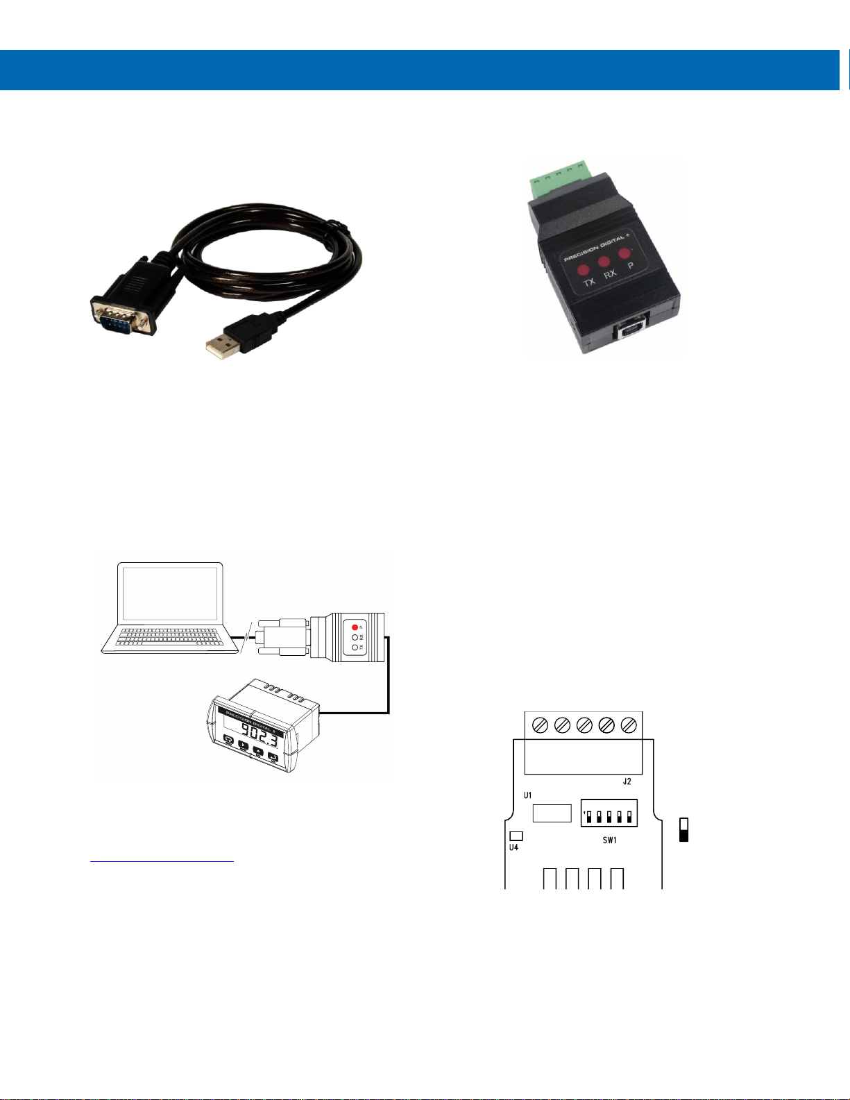
Figure 29 shows the connection of a Trident meter to a
PC using a PDA8232 USB to RS-232 Converter,
PDA7232 RS-232 adapter, and the PDA7420 Modular
Cable.
Figure 29. Connections for PDA8232 to serial device
Driver Download here:
USB Drivers for PDA8232
PDA8485 USB RS-485 Converter
Description
The PDA8485 converts USB to balanced, full or halfduplex RS-422 or RS-485 signals.
The PDA8485 has a removable screw terminal
connector for the RS-485 terminals which includes
Transmit Data (DO) and (/DO), Receive Data (DI) and
(/DI), and Signal Ground.
Baud rates are automatic and handled by the PDA8485.
The PDA8485 has three diagnostic LEDs: a Power (P)
LED to show when the converter is powered properly, a
Transmit Data (TX) LED to show when the converter is
sending data out from the PC side, and a Receive Data
(RX) LED to show when the converter is receiving data
from the network side.
The DIP switch SW1 is located inside the case and
allows for system configurations.
Installation
The DIP switch SW1 allows for several different
options. Factory settings for the switch are shown in
Figure 30.
Figure 30. PDA8485 DIP Switch Location
The termination switch position adds an internal
120 ohm termination resistor when ON (up).
Termination should be used on both ends of the
network with high data rates and long wiring runs.
To configure a two-wire network set both of the 2-wire
switch positions to ON (up). For a four-wire network set
both of the 2-wire switches to OFF (down).
PDA8232
Converter
PDA7232
RS-232 Adapter
PDA7420
Modular Cable
1 234
5
ON
Switch in
ON/UP
Position
Page 17
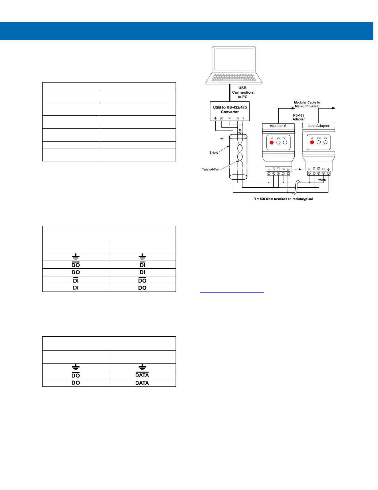
Serial Communication Converters & Adapters
Instruction Manual
17
When the RS-422 switch position is ON (up) and the
RS-485 switch position is OFF (down) it is configured
for an RS-422 network. When the RS-422 switch
position is OFF (down) and the RS-485 switch position
is ON (up) it is configured for an RS-485 network.
PDA8485 DIP Switch Settings
SW1 Switch
Position
ON Setting Function
1
Network Termination
Included (120 ohm)
2
2-Wire Network Mode
Connection (factory setting)
3
2-Wire Network Mode
Connection (factory setting)
4
RS-422 Mode
5
RS-485 Mode (factory
setting)
Figure 31. PDA8485 DIP Switch Settings
Connections
The PDA8485 is powered by the USB port.
The PDA8485 can be configured for either a four-wire
or two-wire network. Figure 32 details the wiring
connections from the PDA8485 to an RS-485 serial
device in a four-wire network.
PDA8485 to RS-485 Serial Device Four-Wire
Connections
PDA8485 Serial
Converter
RS-485 Serial Device
Figure 32. Connections for PDA8485 in a Four-Wire
Network
Figure 33 details the wiring connections from the
PDA8485 to an RS-485 serial device in a two-wire
network when the DIP switches on the PDA8485 have
been set to the “2-Wire Mode”.
PDA8485 to RS-485 Serial Device Two-Wire
Connections
PDA8485 Serial
Converter
RS-485 Serial Device
Figure 33. Connections for PDA8485 in a Two-Wire
Network
The PDA8485 internally connects the /DI to the /DO
and the DI to the DO when the DIP switches are set to
“2-Wire Mode”. Either the /DI or /DO could be used to
connect to /DATA and either the DI or DO could be
used to connect to DATA.
Figure 34 shows an example configuration of a two-wire
network. Each device (e.g. Trident PD765 meter)
connected to the same network must have a unique
address.
Figure 34. PDA8485 RS-485 Two-Wire Multi-Drop Wiring
Notes:
1. Termination resistors are optional and values
depend on the cable length and characteristic
impedance. Consult the cable manufacturer for
recommendations.
2. Refer to PDA7422 Trident RS-485 Serial
Adapter on page 12 for further details.
3. Use shielded cable, twisted-pair plus ground.
Connect ground shield only at one location.
Driver Download here:
USB Drivers for PDA8485
Page 18

Serial Communication Converters & Adapters
Instruction Manual
18
Troubleshooting
Symptom
Check/Action
Power LED is off
PDA1232, PDA1485, PDA7232, or PDA7422
1. Check modular cable connection
2. Check power to meter PDA7485
3. Check wall plug adapter output
4. Check power connection polarity PDA8485
5. Check USB connections
6. Try different USB port
7. Check USB port with other device
Meter not
communicating with
MeterView or other
programs
Check:
1. Serial adapter and cable
2. Serial protocol selected
3. Meter address and baud rate
4. MeterView address and baud rate
5. DIP switch setting on the PDA7485 or PDA8485
If only the TX (or DATA
IN) data status LED is
flashing when serial
communications
attempted
Check:
1. Serial adapter and cable
2. Serial protocol selected
3. Meter address and baud rate
4. MeterView address and baud rate
5. DIP switch setting on the PDA7485 or PDA8485
If both data status LEDs
(TX and RX) are off
when trying to
communicate
Remove all unnecessary cables and meters. Try getting the system to work with only
one meter (to ease troubleshooting) and then expand the system one device at a time.
PDA1232, PDA7232, or PDA7485:
1. Check serial cable
2. Connect the DB9 directly to the PC
3. Try a different serial port
Communications slow
Increase the baud rate
Random communication
errors
1. Increase the TX delay time
2. Decrease the baud rate
Other symptoms not
described above
Call Technical Support for assistance.
Page 19

Serial Communication Converters & Adapters
Instruction Manual
PRECISION DIGITAL CORPORATION
233 South Street • Hopkinton MA 01748 USA
Tel (800) 343-1001 • Fax (508) 655-8990
www.predig.com
LIM7232_O
05/20
Contact Precision Digital
Technical Support
Call: (800) 610-5239 or (508) 655-7300
Fax: (508) 655-8990
Email: [email protected]
Sales Support
Call: (800) 343-1001 or (508) 655-7300
Fax: (508) 655-8990
Email: [email protected]
Place Orders
Email: [email protected]
For the latest version of this manual please visit
www.predig.com
 Loading...