

Page 1
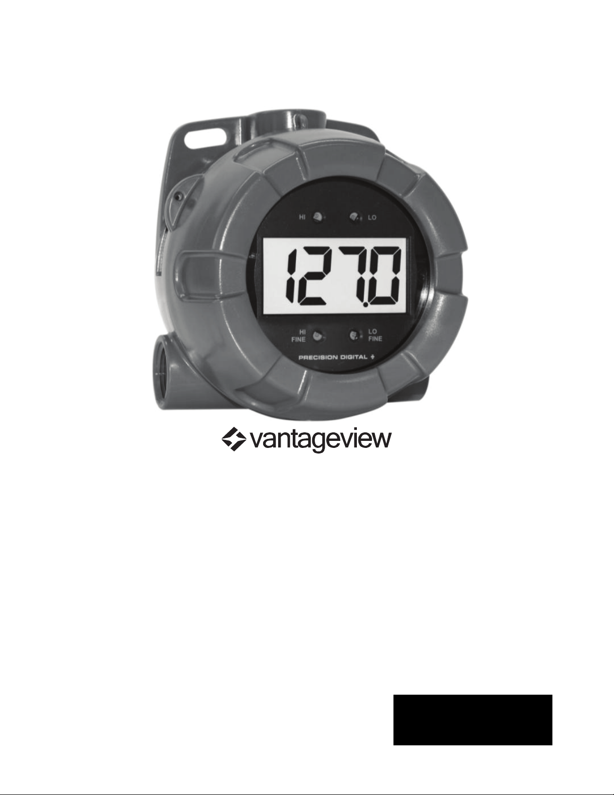
PD6770 VANTAGEVIEW
LOOP-POWERED PROCESS METER
x 4-20 mA
x 1 V drop (4 V with Backlight)
x 3½ Digits LCD, 1" High
x Loop-Powered Backlight Option
x HART® Protocol Transparent
x Plastic NEMA 4X, IP65 Enclosure
x Flanges for Wall or Pipe Mounting
x Easy Calibration and Installation
x Operates from -40 to 75°C
input
PRECISION DIGITAL CORPORATION
Find Quality Products Online at: [email protected]
www.GlobalTestSupply.com
Page 2
PD6770 Loop-Powered Process Meter Instruction Manual
!
CAUTION: Read complete
instructions prior to installation
and operation of the meter.
WARNING: Risk of
electric shock or
personal injury.
Disclaimer
The information contained in this document is subject to change without notice.
Precision Digital makes no representations or warranties with respect to the contents
hereof; and specifically disclaims any implied warranties of merchantability or fitness
for a particular purpose.
WARNINGS
• This product is not recommended for life support applications or applications
where malfunctioning could result in personal injury or property loss. Anyone
using this product for such applications does so at his/her own risk. Precision
Digital Corporation shall not be held liable for damages resulting from such
improper use.
• Failure to follow installation guidelines could result in death or serious injury.
Make sure only qualified personnel perform the installation.
Limited Warranty
Precision Digital Corporation warrants this product against defects in material or
workmanship for the specified period under “Specifications” from the date of
shipment from the factory. Precision Digital’s liability under this limited warranty shall
not exceed the purchase value, repair, or replacement of the defective unit.
Registered Trade
All trademarks mentioned in this document are the property of their respective
owners.
© 2013 Precision Digital Corporation. All rights reserved.
marks
Find Quality Products Online at: [email protected]
www.GlobalTestSupply.com
2
Page 3
PD6770 Loop-Powered Process Meter Instruction Manual
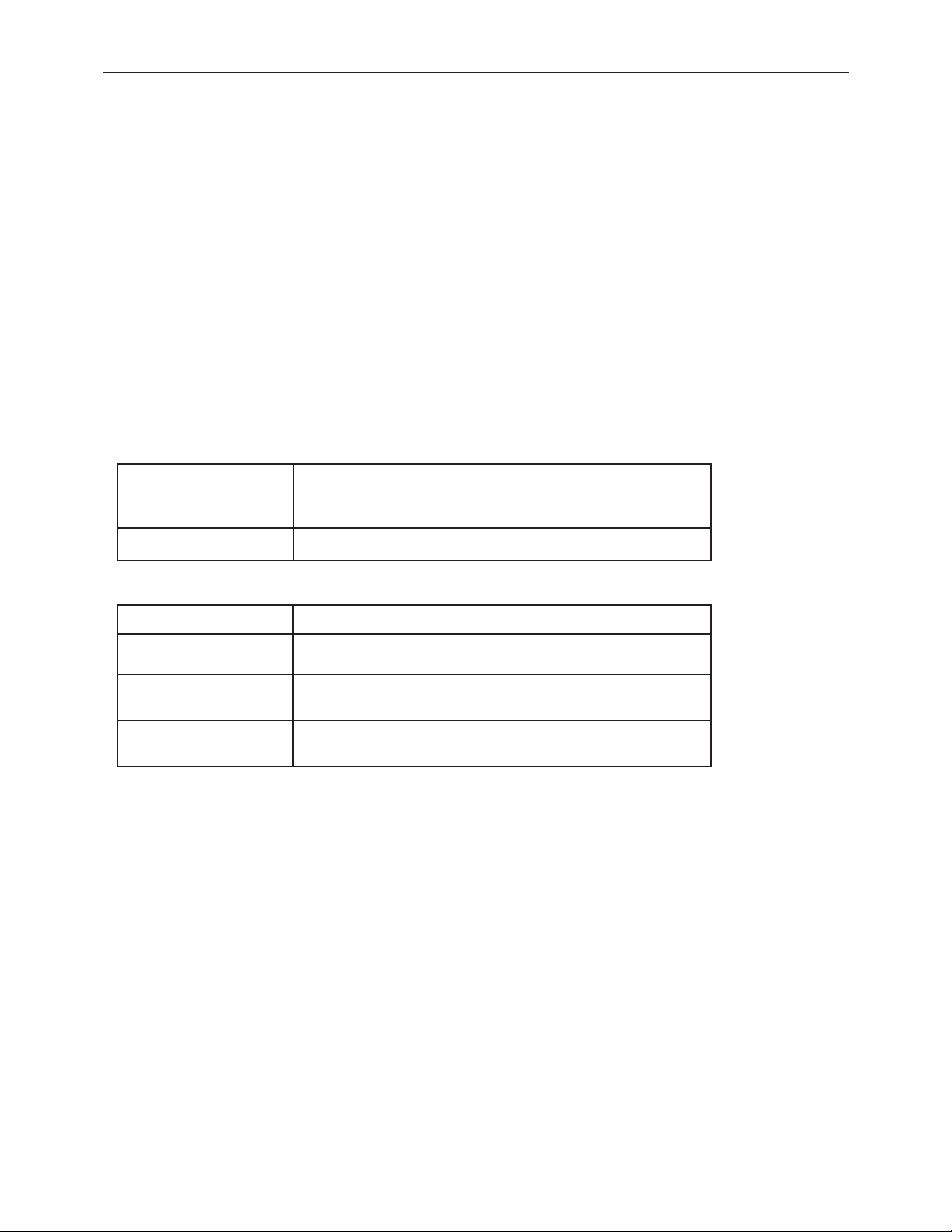
Model
Description
PD6770-0L0
Loop-Powered Process Meter
PD6770-0K0
Loop-Powered Process Meter with Backlight
Model
Description
PDAPLUG75P
3/4" NPT Plastic Conduit Plug
PDA6846
Pipe Mounting Kit. Includes zinc-plated u-bolt
for 2" pipe, (2) washers, and (2) nuts.
PDA6846
Pipe Mounting Kit. Includes stainless steel ubolt for 2" pipe, (2) washers, and (2) nuts.
INTRODUCTION
The Vantageview PD6770 is a rugged, loop-powered meter with 1" display digits.
The plastic NEMA 4X and IP65 field mountable enclosure is designed for demanding
applications in the harshest environmental conditions. The meter derives all of its
power from the 4-20 mA loop with a small 1 volt drop for easy installation in almost
any system.
It is programmed using four easy to access front-mounted control dials with no
complex or difficult to read programming menus necessary for setup. The numeric
display will read from -1999 to 1999 over a 2000 count user adjustable scaling span.
The backlight option lets you see the display under any lighting condition and is
powered from the 4-20 mA loop with no additional power supply required.
The enclosure is provided with two threaded conduit holes and integrated pipe or wall
mounting slotted flanges.
ORDERING INFORMATION
Accessories
-SS
3
Find Quality Products Online at: [email protected]
www.GlobalTestSupply.com
Page 4

PD6770 Loop-Powered Process Meter Instruction Manual
Table of Contents
INTRODUCTION ---------------------------------------------------------------------- 3
ORDERING INFORMATION ------------------------------------------------------- 3
SPECIFICATIONS -------------------------------------------------------------------- 5
General ------------------------------------------------------------------------------------------- 5
Input ----------------------------------------------------------------------------------------------- 6
SAFETY INFORMATION -------------------------------------------------------------------- 7
INSTALLATION ----------------------------------------------------------------------- 8
Unpacking --------------------------------------------------------------------------------------- 8
Conduit/Stopping Plug ---------------------------------------------------------------------- 8
Mounting ----------------------------------------------------------------------------------------- 8
Connections ------------------------------------------------------------------------------------ 9
Connections & Wiring Diagrams ............................................................... 10
SETUP ---------------------------------------------------------------------------------- 11
Scaling Controls and Display ----------------------------------------------------------- 11
Setting Up the Meter ----------------------------------------------------------------------- 12
Calibrating the Meter ................................................................................ 12
Setting the Decimal Point ......................................................................... 12
Factory Defaults & User Settings ----------------------------------------------------- 13
TROUBLESHOOTING ------------------------------------------------------------- 14
Troubleshooting Tips ---------------------------------------------------------------------- 14
MOUNTING DIMENSIONS -------------------------------------------------------- 15
Table of Figures
Figure 1. PD6770 Connectors ................................................................... 9
Figure 2. PD6770 Input Connections without Backlight ....................... 10
Figure 3. PD6770 Input Connections with Loop-Powered Backlight ... 10
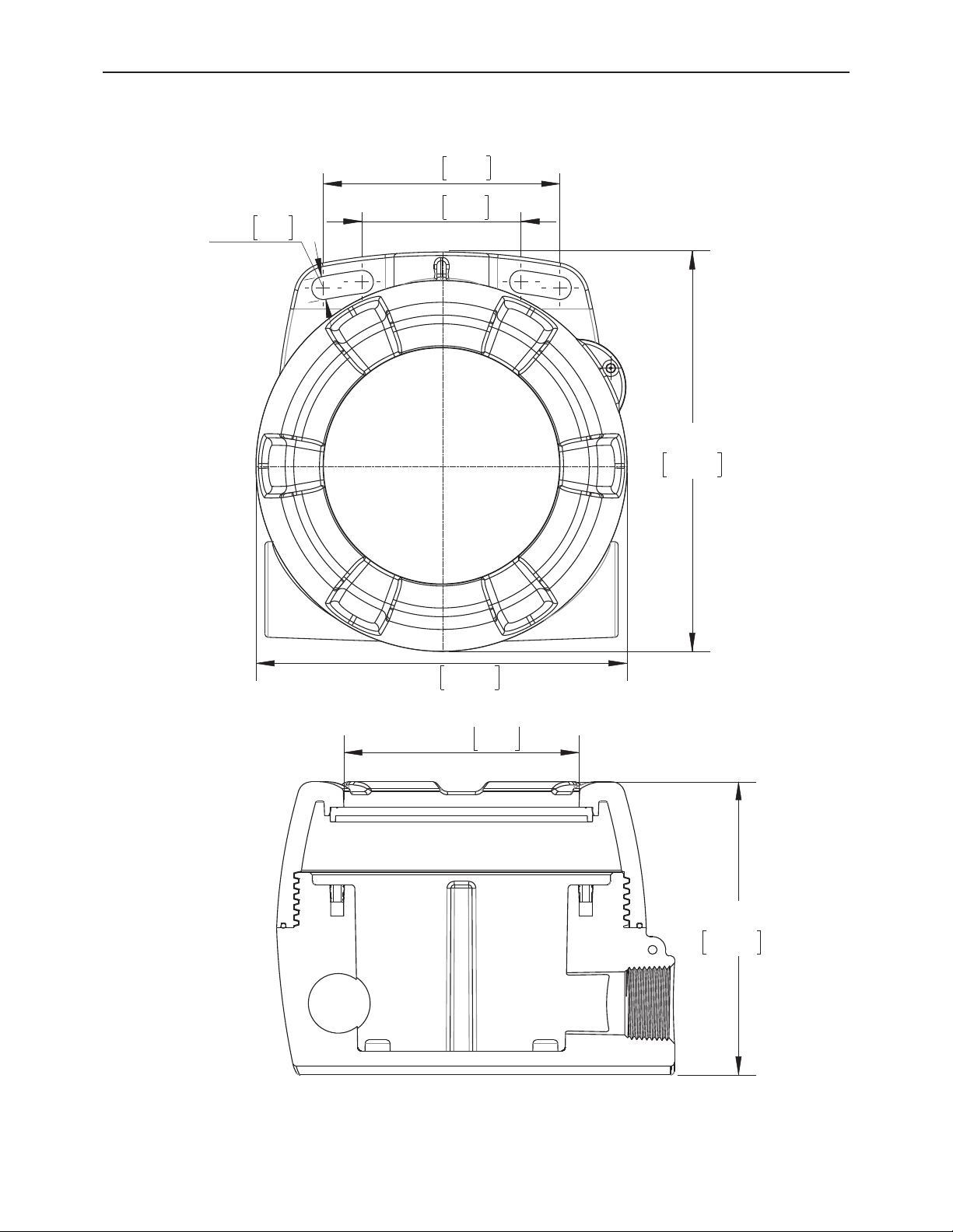
Figure 4. Enclosure Dimensions – Front View ...................................... 15
Figure 5. Enclosure Dimensions – Side Cross Section View ............... 15
4
Find Quality Products Online at: [email protected]
www.GlobalTestSupply.com
Page 5

PD6770 Loop-Powered Process Meter Instruction Manual
DISPLAY
3 ½ digit LCD
1" (25.4 mm); -1999 to 1999
DISPLAY
UPDATE RATE
2.5 Updates/Second
OVERRANGE
Display reads 1 on the left most digit
PROGRAMMING
METHOD
Four front mounted rotary control dials accessed when the
cover is removed.
RECALIBRATION
Recalibration is recommended at least every 12 months.
NORMAL MODE
REJECTION
60 dB rejection ratio
ENVIRONMENTA L
Operating temperature range: -40 to 75°C
Storage temperature range:
Relative humidity: 0 to 90% non-condensing
CONNECTIONS
Screw terminals accept 12 to 22 AWG wire
ENCLOSURE
NEMA 4X, IP65 plastic field enclosure.
Color:
Three ¾" NPT thread
plastic
screwdriver slot, is included.
MOUNTING
May be mounted directly to conduit. Two slotted flanges for
wall mounting or NPS 1½" to 2½" or DN 40 to 65 mm pipe
mounting. See Mounting Dimensions on page 15.
OVERALL
DIMENSIONS
5.67" x 5.25" x 4.18" (W x H x D)
(144 mm x 133 mm x 106 mm)
WEIGHT
1.65 lbs (26.4 oz, 0.75 kg)
WARRANTY
3 years parts and labor
SPECIFICATIONS
Except where noted all specifications apply to operation at +25°C.
General
-40 to 75°C
grey.
ed conduit openings. One ¾" NPT
conduit plug, with 1.29" wrenching flats and a
Find Quality Products Online at: [email protected]
www.GlobalTestSupply.com
5
Page 6

PD6770 Loop-Powered Process Meter Instruction Manual
ACCU RACY
±0.1% of full span ±1 count
TEMPERATURE
DRIFT
150
DECIMAL POINT
User selectable decimal point
CALIBRATION
RANGE
4 mA input: -1000 to +1000; 20 mA between 20 and 2000
counts greater than 4 mA display.
Two point linear display span.
MAXIMUM
VO
Without Backlight
With Loop-Powered
Backlight
1 VDC @ 20 mA
4 VDC @ 20 mA
EQUIVALENT
RESISTANCE
50 Ω @ 20 mA
200 Ω @ 20 mA
INPUT
OVERLOAD
Over current protection to 2 A max.
Input
PPM/qC from -40 to 75qC ambient
LTAGE DROP
Find Quality Products Online at: [email protected]
www.GlobalTestSupply.com
6
Page 7
PD6770 Loop-Powered Process Meter Instruction Manual
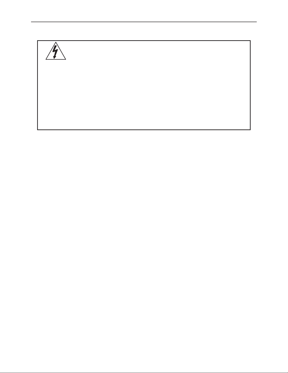
WARNINGS
x Read complete instructions prior to installation and operation of the meter.
must be
tight while
installation error occurs, high voltage may be present on any lead
SAFETY INFORMATION
x Installation and service should be performed only by trained service
personnel. Service requiring replacement of internal components
performed at the factory.
x Disconnect from supply before opening enclosure. Keep cover
circuits are alive.
x If the meter is installed in a high voltage environment and a fault or
7
Find Quality Products Online at: [email protected]
www.GlobalTestSupply.com
Page 8
PD6770 Loop-Powered Process Meter Instruction Manual
WARNING
Hazardous voltages
Installation and service should be performed only by trained
service personnel.
WARNING
Do not attempt to loosen or remove flange bolts while the meter is
in service.
INSTALLATION
All controls and wiring connectors are accessed by opening the enclosure. To access
electrical connectors, remove the 2 captive screws and remove the display module
from the enclosure.
may exist within enclosure.
Unpacking
Remove the meter and conduit plug from box. Inspect the packaging and contents for
damage. Report damages, if any, to the carrier. If any part is missing or the meter
malfunctions, please contact your supplier or the factory for assistance.
Conduit/Stopping Plug
The PD6770 includes three ¾" NPT threaded conduit openings and one IP68 rated
¾" NPT plastic conduit plug.
The conduit/stopping plug included has 1.29" wrenching flats and a screwdriver slot.
Mounting
The PD6770 has two slotted mounting flanges that may be used for pipe mounting or
wall mounting. Alternatively, the unit may be supported by the conduit using the
conduit holes provided.
Refer to Mounting Dimensions, page 15 for details.
Find Quality Products Online at: [email protected]
www.GlobalTestSupply.com
8
Page 9
PD6770 Loop-Powered Process Meter Instruction Manual
WAR
NINGS
x Static electricity can damage sensitive components.
terminal.
S+
4-20 mA signal input positive terminal connection
S-
4-20 mA signal return/negative terminal connection
B-
4-20 mA signal return/negative terminal when using the installed loop
powered backlight option.
WA
R
NING
Observe all safety regulations. Electrical wiring should be
performed in accordance
applicable national, state, and local codes to prevent damage to
the meter and ensure personnel safety.
Connections
x Observe safe handling precautions for static -sens itive components.
x Use proper grounding procedures/codes.
x If the meter is installed in a high voltage environment and a fault or
installation error occurs, high voltage may be present on any lead or
To acce
screws that fasten the display module. Remove the display module. Signal
connections are made to a three-term inal connect or on t he rear of the display
module.
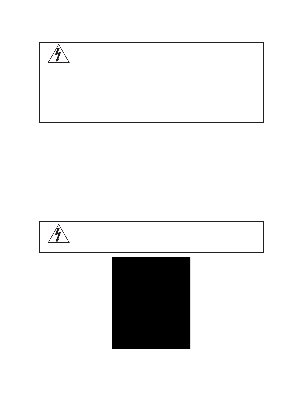
Refer to Figure 1 for terminal positions.
ss the connectors, remove the enclosure cover and unscrew the two captive
with all agency requirements and
Figure
Find Quality Products Online at: [email protected]
www.GlobalTestSupply.com
1. PD6770 Connectors
9
Page 10

PD6770 Loop-Powered Process Meter Instruction Manual
Connections & Wiring Diagrams
Signal connections are made to a three-terminal connector m ounted on t he rear of
the display module. The enclosure also provides one internal and one external earth
grounding screw. The 4-20 mA input with no backlight has a maximum voltage drop
of 1 V and is wired as shown in Figure 2. The loop-powered backlight configuration
requires a total maximum voltage drop of 4 V. The backlight option is recommended
for dim lighting conditions and is enabled when wired as shown in Figure 3.
Figure 2. PD6770 Input Connections without Backlight
Figure 3. PD6770 Input Connections with Loop-Powered Backlight
10
Find Quality Products Online at: [email protected]
www.GlobalTestSupply.com
Page 11
PD6770 Loop-Powered Process Meter Instruction Manual
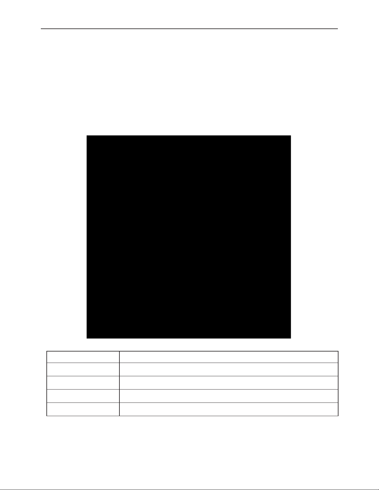
Control
Description
LO
4 mA display adjust.
LO FINE
4 mA precision display adjust.
HI
20 mA display adjust.
HI FINE
20 mA precision display adjust.
SETUP
Overview
Setup is done using four rotary control dials located on the front of the display
module that are accessed when the meter cover is removed. Setup is performed
using a 4-20 mA signal source and scaling the 4 and 20 mA readings using the
control dials.
Scaling Controls and Display
11
Find Quality Products Online at: [email protected]
www.GlobalTestSupply.com
Page 12

PD6770 Loop-Powered Process Meter Instruction Manual
Setting Up the Meter
Calibrating the Meter
The meter is provided factory calibrated to display -50. 0 at 4 mA and 150.0 at 20 mA.
HI and LO coarse and fine controls are labeled on the front of the display. Use the HI
and LO controls for large range changes during calibration and the HI FINE and LO
FINE controls for precision changes.
Apply a 4 mA signal and adjust the LO controls to display the desired reading. Apply
a signal between 16 and 20 mA and adjust the HI controls to display the desired
reading. Complete the calibration procedure by making minor adjustments to the LO
and HI controls as necessary.
Minimum & Maximum Input Span
A minimum input span of 20 counts is required between a 4 mA and 20 mA input. A
maximum input span of 2000 counts may be setup between a 4 mA and 20 mA input.
The meter will not properly calibrate or display if these minimum and maximum span
ranges are not maintained during scaling.
Setting the Decimal Point
Decimal point may be set using a three position jumper on the rear of the display
module. To access the connectors, unscrew the two captive screws that fasten the
display module. Remove the display module and place the jumper on the desired
pins as indicated on the board for decimal point locations of D.DDD, DD.DD, DDD.D,
or remove it if no decimal point is desired.
12
Find Quality Products Online at: [email protected]
www.GlobalTestSupply.com
Page 13

PD6770 Loop-Powered Process Meter Instruction Manual
Parameter
Default
Setting
User Setting
Decimal point
1 place
Calibration Settings
Input 1
4.00 mA
Display 1
-50.0
Input 2
20.00 mA
Display 2
150.0
Factory Defaults & User Settings
The following table shows the factory setting for most of the programmable
parameters on the meter. Next to the factory setting, the user may record the new
setting for the particular application.
Model: ______________ S/N: _______________ Date: _________
Find Quality Products Online at: [email protected]
www.GlobalTestSupply.com
13
Page 14
PD6770 Loop-Powered Process Meter Instruction Manual
Symptom
Check/Action
No display
Check input signal connections.
Rate display unsteady during
calibration
Adjust LO FINE or HI FINE
controls to fine-tune the display.
Meter displays 1 on the left
most digit location
Check signal level is not over
range.
Dial down the HI control and recalibrate at 20 mA.
Display is faded
Check input signal is not under
1 mA.
If the display locks up or the
meter does not respond at all
Perform hard reset by shorting
S+ and S- terminals.
Backlight does not appear
Verify backlight is installed.
Check signal connections are as
shown in Figure 3 on page 10.
Other symptoms not described
above
Call Technical Support for
assistance.
TROUBLESHOOTING
The rugged design and the user-friendly interface of the meter should make it
unusual for the installer or operator to refer to this section of the manual. If the meter
is not working as expected, refer to the recommendations below.
Troubleshooting Tips
Find Quality Products Online at: [email protected]
www.GlobalTestSupply.com
14
Page 15
PD6770 Loop-Powered Process Meter Instruction Manual
MOUNTING DIMENSIONS
All units: in ches [mm]
0.33
8.3
3.35
2.25
85.1
57.2
5.67
144.0
Figure
5.25 133.3
Figure
4. Enclosure Dimensions – Front View
Ø
3.34
84.9
4.18
106.1
5. Enclosure Dimensions – Side Cross Section View
Note: The supplied conduit plug may extend up to 0.21 in [5.3 mm] from the conduit
opening when installed.
15
Find Quality Products Online at: [email protected]
www.GlobalTestSupply.com
Page 16

PD6770 Loop-Powered Process Meter Instruction Manual
LIM6770_A
10/13
Find Quality Products Online at: [email protected]
www.GlobalTestSupply.com
 Loading...