

Precision Digital PD6730-APA-0, PD6730-BMA-I, PD6730-CTB-0, PD6730-BM0-I, PD6730-AP0-0 User manual
...Page 1

PD6730 Vantageview Pulse Input Rate/Totalizer
Instruction Manual
Rate/Totalizer
Pulse, Open Collector, NPN, PNP, TTL, Switch Contact, Sine Wave (Coil), Square
Wave, Opto-Isolated Inputs
Plastic NEMA 4X, IP65 Enclosure
Isolated 4-20 mA Output for Rate, Total, or Grand Total
5-Digit 0.7" (17.8 mm)Top Display for Rate or Total
7 Alphanumeric Character 0.4" (10.2 mm) Bottom Display for Rate, Total, Grand
Total, Units, and Tag
13-Digit Totalizer with Total Overflow Feature
SafeTouch Through-Window Button Programming
Battery, DC, or Output Loop-Powered Models
Two Isolated Open Collector Pulse Outputs, Up to 5 kHz
Automatic Rate, Total, & Grand Total Unit Conversions
Password Protection
Backlight Standard on All Models
Operates from -40 to 75°C
Data Logging Functions and Modbus® Accessible Data
PRECISION DIGITAL CORPORATION
Find Quality Products Online at: [email protected]
www.GlobalTestSupply.com
Page 2
PD6730 Vantageview Pulse Input Rate/Totalizer Instruction Manual
Disclaimer
CAUTION: Read complete
instructions prior to installation
and operation of the meter.
WARNING: Risk of
electric shock or
personal injury.
Model
Description
PD6730-AP0-0
9-30 VDC Powered, Constant
Backlight, 2 Pulse Outputs
PD6730-APA-0
9-30 VDC Powered, Constant
Backlight, Isolated 4-20 Output,
2 Pulse Outputs
PD6730-BM0-0
Battery Powered*, or DC-Powered with
Battery Backup, Backlight**,
2 Pulse Outputs
PD6730-BMA-0
Battery (or 9-30 VDC) Powered*, or DC
Powered with Battery Backup,
Backlight**, Isolated 4-20 mA Output,
2 Pulse Outputs
PD6730-BTA-0
Battery Powered*, or DC Powered with
Battery Backup, Loop Output Powered
Backlight, Isolated 4-20 Output,
2 Pulse Outputs
PD6730-CTB-0
4-20 mA Output-Powered, LoopPowered Backlight, Non-Isolated
4-20 mA Output, 2 Pulse Outputs
PD6730-DTB-0
4-20 mA Output-Powered with Battery
Backup, Loop Output Powered
Backlight**, Non-Isolated 4-20 mA
Output, 2 Pulse Outputs
-I Option
Isolated 2-wire RS-485 with Modbus
protocol.***
Replace ending -0 in part number
above with -I
(Example: PD6730-APA-I). Not
available on -CTB or -DTB models.
* When DC-powered, battery will provide backup power when
DC power is lost.
** Backlight is constant when DC powered and momentary
when battery powered.
***Communication disabled when actively powered by battery.
Model
Description
PDAPLUG75P
3/4" NPT Plastic Conduit Plug
PDABAT36C
3.6 V C Cell Lithium Battery
!
The information contained in this document is subject to
change without notice. Precision Digital makes no
representations or warranties with respect to the contents
hereof; and specifically disclaims any implied warranties of
merchantability or fitness for a particular purpose.
INTRODUCTION
The Vantageview PD6730 is a plastic field mounted
rate/totalizer designed for rugged and demanding
applications in harsh environments. It can be programmed
using the four SafeTouch through-window buttons, without
removing the cover, or with four internal push-buttons. The
top numeric display will read rate or total up to five digits and
the alphanumeric bottom display will read up to 7 digits,
13 digits with the total overflow feature. The bottoms display
can also show up to seven characters for rate, total, grand
total, engineering units and/or identification tag. The
backlight makes the display more visible in any lighting
condition. The enclosure has three threaded conduit holes,
integrated pipe or wall mounting flanges, and allows for easy
installation of tamper seals.
WARNINGS
This product is not recommended for life support
applications or applications where malfunctioning could
result in personal injury or property loss. Anyone using
this product for such applications does so at his/her
own risk. Precision Digital Corporation shall not be held
liable for damages resulting from such improper use.
Failure to follow installation guidelines could result in
death or serious injury. Make sure only qualified
personnel perform the installation.
Cancer and Reproductive Harm
www.P65Warnings.ca.gov. For California Proposition
65 details please visit our website www.predig.com
Limited Warranty
Precision Digital Corporation warrants this product against
defects in material or workmanship for the specified period
under “Specifications” from the date of shipment from the
factory. Precision Digital’s liability under this limited warranty
shall not exceed the purchase value, repair, or replacement
of the defective unit.
Registered Trademarks
SafeTouch is a registered trademark of Precision Digital
Corporation. All other trademarks mentioned in this
document are the property of their respective owners.
© 2013-2019 Precision Digital Corporation. All rights
reserved.
www.predig.com
ORDERING INFORMATION
Accessories
Find Quality Products Online at: [email protected]
www.GlobalTestSupply.com
2
Page 3

PD6730 Vantageview Pulse Input Rate/Totalizer Instruction Manual
Table of Contents
INTRODUCTION ........................................................ 2
ORDERING INFORMATION...................................... 2
SPECIFICATIONS ..................................................... 4
General .......................................................................... 4
Rate Input ...................................................................... 5
Rate/Totalizer ................................................................ 6
4-20 mA Transmitter Output ......................................... 6
Open Collector Outputs ................................................ 7
Serial Communications ................................................ 7
SAFETY INFORMATION ................................................ 7
INSTALLATION ......................................................... 8
Unpacking ..................................................................... 8
Conduit/Stopping Plug ................................................. 8
Battery Activation Pull Tab ........................................... 8
Mounting ....................................................................... 8
Connections .................................................................. 8
Input Signal Connections ........................................... 9
DC Power Connection ................................................ 9
External Total Reset Connection .............................. 10
4-20 mA Transmitter Output Connections................. 10
RS-485 Serial Connections ...................................... 10
Open Collector Output Connections ......................... 10
Battery Replacement ................................................ 11
SETUP AND PROGRAMMING ............................... 11
SafeTouch Buttons ..................................................... 11
Buttons and Display ................................................... 12
Setting Numeric Values .............................................. 13
Setting Alphanumeric Labels (LABEL) ........................ 13
Main Menu ................................................................... 13
Setup Menu Display Functions & Messages ............. 14
Setting Up the Meter (SETUP) ...................................... 16
Selecting Input Type (Input).................................... 16
Input Level Selection Switch ................................ 17
Entering the K-Factor (Factr) .................................. 17
K-Factor Units (FuNiT) ........................................ 17
K-Factor Decimal Point (dec.pt) .......................... 17
K-Factor Value (factr) ....................................... 17
Display Units (Units) ............................................... 18
Setting the Time Base (tbase) ............................ 18
Setting the Rate Display Units (rateU) ................ 19
Total Units (tot U) .............................................. 19
Grand Total Units (GtotU) ................................... 20
Automatic Unit Conversions ................................ 20
Custom Units Entry (USER) .................................. 20
Custom Units Rate Conversion Factor (ratCF) .... 20
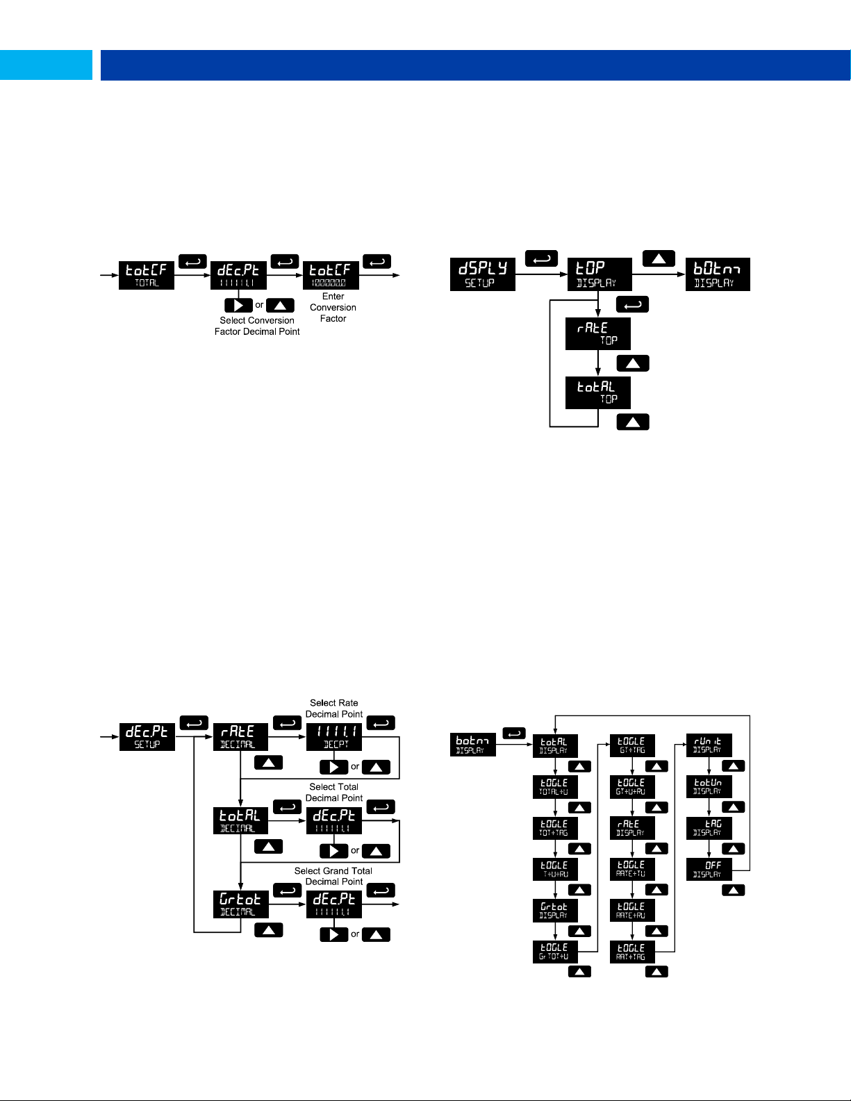
Custom Units Total Conversion Factor (totCF) ... 21
Custom Units Grand Total Conversion Factor
(GrtCF) ........................................................ 21
Setting the Decimal Point (dec.PT) ............................ 21
Configuring the Display (Dsply) ............................... 21
Top Display (TOp) ................................................ 21
Bottom Display (bOtnm) ....................................... 21
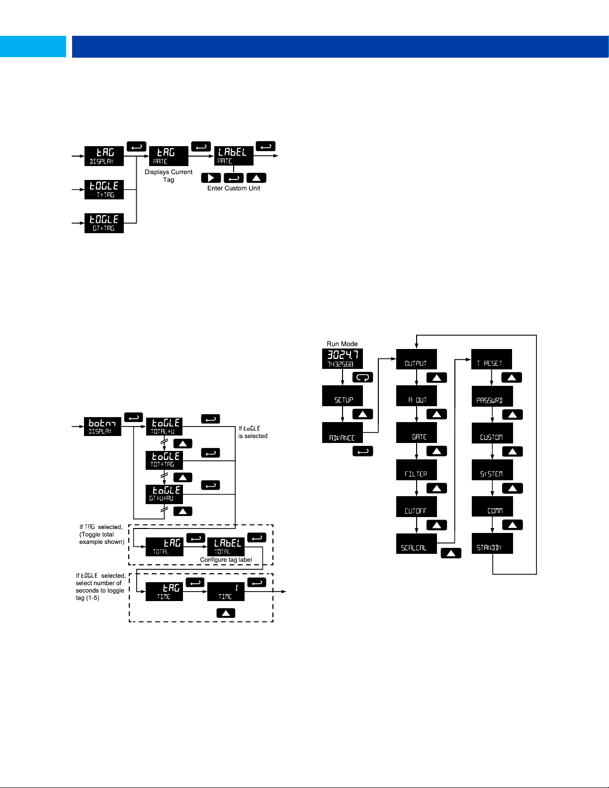
Custom Tag (TAG)................................................ 22
Setting the Toggle Time (TIME) ........................... 22
Advanced Features Menu ........................................... 22
Advanced Features Menu & Display Messages........ 23
Open Collector Outputs (OUTPUT) ............................. 25
Output 1 and 2 Setup (OUT 1, OUT 2) .................. 25
Scaling the 4-20 mA Analog Output (Aout) .............. 27
Gate Function (GATE) ............................................... 27
Contact Debounce Filter (FILTER) ............................ 27
Low-Flow Cutoff (CUTOFF) ........................................ 27
Scaling & Calibration (SCALCAL) ............................... 28
Undoing K-Factor, Scale, and Calibration (Undo?)28
Scaling the Meter (SCale) ................................... 28
Calibrating the Meter (CaL) .................................. 29
Multi-Point Linearization (nopts) ......................... 30
Total Reset (T Reset) ............................................. 30
Manual or Automatic Total Reset Function (t rST)30
Manual or Automatic Grand Total Reset Function
(GtrST) ....................................................... 31
Setting Up Passwords (PASSWRD) ........................ 31
Locking Meter Setup Parameters ........................ 31
Making Changes to a Password Protected Meter 31
Password Restricting Total & Grand Total Reset 32
Resetting Total & Grand Total on a Password
Protected Meter .......................................... 32
Disabling Password Protection ............................ 32
Non-Resettable Grand Total ............................... 32
Custom (CUSTOM) ..................................................... 33
System (SYSTEM) ..................................................... 34
Set Real Time Clock (SETTIME) .......................... 34
Data Log Setup (DATALOG) .................................. 34
View Data Log (LOGVIEW) .................................... 35
Backlight (BAKLITE) ............................................ 35
Analog Output Calibration (AO CAL) .................... 35
Backup & Restore (BACKUP) ................................ 35
Battery Power Symbol Alert (BAT SYM) ............... 35
Information (INFO) ............................................... 36
Serial Communications (COMM) ................................. 36
Standby Mode (STANDBY)......................................... 36
Wakeup the Meter (WAKEUP?) .............................. 36
OPERATION ............................................................ 37
Front Panel Buttons Operation .................................. 37
Grand Total Reading .................................................. 38
Toggle Lower Display Parameter .............................. 38
Resetting the Total (RESET TOTAL?)............................ 38
Resetting the Grand Total (RESET GrTOT?) ................ 38
Resetting Max/Min Readings (RESET MAXIMUM,
MINIMUM) ...................................................................... 38
Reset Meter to Factory Defaults ................................ 39
Factory Defaults & User Settings .............................. 39
TROUBLESHOOTING ............................................. 40
Troubleshooting Tips ................................................. 40
MOUNTING DIMENSIONS ...................................... 40
QUICK USER INTERFACE REFERENCE .............. 41
Table of Figures
Figure 1. Connector Board ...................................... 8
Figure 2. Flowmeter Powered by External Supply
(Active) .............................................................. 9
Figure 3. Isolated Flowmeter Powered by External
Supply (ISO) ...................................................... 9
Figure 4. Self-Powered Magnetic Pickup Coil
Flowmeter (Coil) ............................................... 9
Figure 5. NPN Open Collector Input (NPN) ............ 9
Figure 6. PNP Sensor with External Power (PNP) . 9
Figure 7. Switch Contact Input (Reed) ................... 9
Figure 8. DC Power Connections ............................ 9
Figure 9. Reset Connections ................................. 10
Figure 10. 4-20 mA Output Connections .............. 10
Figure 11. RS-485 2 Wire Serial Connections ...... 10
Figure 12. RS-485 4 Wire Serial Connections ...... 10
Figure 13. Open Collector Output Connections .. 10
Figure 14. Battery Orientation ............................... 11
Figure 15. Date Display Example .......................... 34
Figure 16. Enclosure Dimensions – Front View .. 40
Figure 17. Enclosure Dimensions – Side View .... 40
3
Find Quality Products Online at: [email protected]
www.GlobalTestSupply.com
Page 4

PD6730 Vantageview Pulse Input Rate/Totalizer Instruction Manual
DISPLAY
Five Digits
Top
Display (0
to 99999)
0.7" (17.8 mm) high,
7-segment,
automatic lead zero
blanking.
Seven
Characters
Bottom
Display
0.4" (10.2 mm) high,
14-segment,
automatic lead zero
blanking.
Symbols
Total, grand total,
battery power/low
battery, high alarm, low
alarm, SafeTouch
button sleep
mode/disable, password
lock
DISPLAY
ASSIGNMENT
Top Display: Rate or total
Bottom Display: Combinations of
rate, total, grand total, units, and
custom tag
BACKLIGHT
White LED, 10 second auto-off
when battery powered
Backlight deactivated below
temperatures ≈ -20°C
ALARM
INDICATION
Flashing display plus HI/LO (rate) or
SET (total) indicators
DISPLAY
UPDATE RATE
Ambient > -20°C: 1 Update/Second
Ambient < -20°C: 1 Update/10
Seconds
Note: Update is dependent on gate
settings.
OVERRANGE
Display flashes 99999
PROGRAMMING
METHODS
Four SafeTouch through-window
buttons when cover is installed.
Four internal pushbuttons when
cover is removed.
RECALIBRATION
All ranges are calibrated at the
factory to read frequency in Hz. No
recalibration required.
MAX/MIN
DISPLAY
Max/Min readings reached by the
process are stored until reset by the
user or until power to the meter is
cycled.
PASSWORD
MENU OPTIONS
Three programmable password
selections can be used for the
following: restrict modification of
settings, prevent resetting the total or
grand total without the password, or
permanently lock out the ability to
change or reset the grand total or
any grand total related settings
(making a non-resettable grand
total).
Pass: Restricts modifications of
programmed settings to require reentering the password to make
changes.
Pass T: Restricts the reset of total to
require re-entering the password.
Disables the manual mode reset
contact.
PASSWORD
MENU OPTIONS
(CONTINUED)
Pass GT: Restricts the reset of grand
total to Require re-entering the
password. May enable a nonresettable grand total and permanent
lockout of grand total-related settings
with a specific password.
POWER
OPTIONS
9-30 VDC Powered, 2.2 W max
4-20 mA Output Powered,
30 VDC max
Battery Power
9-30 VDC Powered with Battery
Backup
4-20 mA Output Powered with
Battery Backup
BATTERY
3.6 V Primary Lithium (Li-SOCl2),
non-rechargeable
Model PDABAT36C
Expected Service Life &
Recommended Replacement
Interval
Operating
Condition
Estimated
Service
Life
Suggested
Replacement
Interval
Open
collector
outputs
off,
SafeTouch
buttons
off,
minimal
backlight
use
7.5
years
5.5
years
<100 Hz
open
collector
outputs,
minimal
SafeTouch
button or
backlight
use
5.5
years 4 years
<2 kHz
open
collector
outputs,
minimal
SafeTouch
button or
backlight
use
2.5
years 2 years
<5 kHz
open
collector
outputs,
minimal
SafeTouch
button or
backlight
use
1.3
years 1 year
Backup
power only
N/A
10
years
SPECIFICATIONS
Except where noted all specifications apply to operation at
+25°C.
General
Find Quality Products Online at: [email protected]
www.GlobalTestSupply.com
4
Page 5

PD6730 Vantageview Pulse Input Rate/Totalizer Instruction Manual
DATA LOGGING
Up to 1024 records, recorded 4/day
at specific times or at defined time
intervals. Record contains date,
time, rate, total, grand total, and log
number.
ISOLATION
All Models:
500 V optoisolated input-topower/output with
isolated input
enabled
PD6730-BTA:
500 V input-tooutput
PD6730-APA:
500 V input/powerto-output
Note: Requires
separate output
supply
ENVIRONMENTAL
Operating temperature range:
-40 to 75°C
Storage temperature range:
-40 to 75°C
Backlight deactivated below
temperatures ≈ -20°C
Relative humidity: 0 to 90%
non-condensing
NON-VOLATILE
MEMORY
All program bned settings and total
reading are stored in non-volatile
memory for a minimum of ten years
if power is lost.
CONNECTIONS
Screw terminals accept 12 to 22
AWG wire
ENCLOSURE
NEMA 4X, IP65 plastic field
enclosure.
Color: grey.
Three ¾" NPT threaded conduit
openings. One ¾" NPT plastic
conduit plug, with 1.29" wrenching
flats and a screwdriver slot, is
included.
MOUNTING
May be mounted directly to conduit.
Two slotted flanges for wall
mounting or NPS 1½" to 2½" or DN
40 to 65 mm pipe mounting. See
Mounting Dimensions on page 40.
OVERALL
DIMENSIONS
5.67" x 5.25" x 4.18" (W x H x D)
(144 mm x 133 mm x 106 mm)
WEIGHT
1.65 lbs (26.4 oz, 0.75 kg)
WARRANTY
3 years parts and labor
Rate Input
PULSE/
TRANSISTOR/
CONTACT
CLOSURE
INPUT
Field selectable; Sourcing or sinking
pulse or square wave
0-5 V, 0-12 V, or 0-24 V; TTL; NPN or
PNP transistor;
Open collector 100 kΩ pull-up to 3 V;
Switch contact 100 kΩ pull-up to 3 V;
PNP transistor 100 kΩ pull-down to
ground (COM)
Active input 100 kΩ to battery level,
10 kΩ to power
Maximum Frequency: 64 kHz
Minimum Pulse Width: 5 µs
Threshold Setting
Low (V)
High (V)
Normal
1.2
2.0
Low
0.2
1.2
OPTOISOLATED
INPUT
Sourcing pulse or square wave 0-5 V, 012 V, or 0-24 V; Logic High: 2-24 V,
Logic Low: < 1 V
Maximum Frequency: 20 kHz
Minimum Pulse Width: 20 µs
Input Current: 1 mA @ 5 V, 2.5 mA @
12 V, 5 mA @ 24 V
LOW VOLTAGE
MAG PICKUP
INPUT
Sensitivity: 20 mVp-p to 24 Vp-p
Maximum Frequency: 6 kHz
MINIMUM
INPUT
FREQUENCY
0.0001 Hz. Minimum frequency is
dependent on high gate setting (rate
display).
INPUT
IMPEDANCE
Pulse input: Greater than 75 k @ 1 kHz.
Open collector/switch input: 100 k
pull-up to 3 V.
ACCURACY
±0.03% of calibrated span ±1 count
TEMPERATURE
DRIFT
Rate display is not affected by changes
in temperature.
LOW-FLOW
CUTOFF
0-99,999 (0 disables cutoff function)
DECIMAL
POINT
Up to four decimal places or none:
4.4444, 33.333, 222.22, 1111.1, or
00000
CALIBRATION
May be calibrated using K-Factor, scale
without signal source, or by applying an
external calibration signal.
K-FACTOR
Field programmable K-Factor converts
input pulses to rate in engineering units.
May be programmed from 0.000001 to
9,999,999 pulses/unit.
CALIBRATION
RANGE
Input 1 signal must be ≥ 1 Hz; input 2
signal may be set anywhere above input 1
setting. Minimum input span is 1 Hz.
An Error message will appear if the
input 1 and input 2 signals are too close
together.
INPUT
CONTACT
DEBOUNCE
FILTER
Programmable contact debounce filter.
Input signal frequency speed selections
of Hi (no filter), Med (250 Hz max input,
2 ms pulse width), and Low (100 Hz
max input, 5 ms minimum pulse width).
TIME BASE
Second, minute, hour, or day
GATE
Low gate: 1-99 seconds; High gate: 29,999 seconds
Find Quality Products Online at: [email protected]
www.GlobalTestSupply.com
5
Page 6

PD6730 Vantageview Pulse Input Rate/Totalizer Instruction Manual
Rate/Totalizer
DISPLAY
ASSIGNMENT
The Top display is assigned to rate or
total. The Bottom display is
programmable to display total; total and
units; total and tag; total, total units,
and rate units; grand total; grand total
and grand total units; grand total and
tag; grand total, grand total units, and
rate units; rate units; rate; rate and total
units; rate and rate units; rate and tag;
rate units; total units; a custom tag; or
be off (blank).
RATE DISPLAY
UNITS
Gallons, liters, imperial gallons, cubic
meters, barrels, bushels, cubic yards,
cubic feet, cubic inches, liquid barrels,
beer barrels, hectoliters, or custom.
RATE DISPLAY
TIME BASE
Rate display may be calculated in
terms of units per second, minute,
hour, or day.
TOTAL & GRAND
TOTAL DISPLAY
UNITS
Gallons, liters, imperial gallons, cubic
meters, barrels, bushels, cubic yards,
cubic feet, cubic inches, liquid barrels,
beer barrels, hectoliters, or custom.
Setting is independent for each.
TOTAL & GRAND
TOTAL DISPLAY
UNIT
MULTIPLIER
x1, x100 (h), x1000 (k), or x1,000,000
(M) multiplier (and prefix) applied to
total or grand total display units. Setting
is independent for each.
TOTAL & GRAND
TOTAL DECIMAL
POINT
Up to six decimal places or none:
6.666666, 55.55555, 444.4444,
3333.333, 22222.22, 111111.1 or
0000000
Total and grand total decimal points
are independently programmed, and
are independent of rate decimal point.
TOTALIZERS
Calculates total and grand total based
on rate and field programmable
multiplier to display total in engineering
units. Time base must be selected
according to the time units in which the
rate is displayed. The total and grand
total utilize the same time base, with
different conversion factors and resets.
TOTALIZER
RESET
Via SafeTouch RESET button,
mechanical button (cover off), external
contact closure (total only),
automatically via user selectable preset
value and time delay (1 – 99,999 sec).
Manual reset may be disabled or
protected by password for the total and
grand total. Total and grand total reset
independently.
TOTAL
OVERFLOW AND
ROLLOVER
The total can display up to
9,999,999,999,999. Up to 9,999,999
can be displayed on the lower display
normally. An overflow display will
toggle between the first six digits and
last seven digits (999999 <> 9999999)
for a 13-digit total. The total will rollover
beyond thirteen digits. The T indicator
on the display will flash to indicate total
overflow, and the six most significant
digits (first six numbers of the total) are
indicated with the flashing overflow
symbol .
GRAND TOTAL
OVERFLOW AND
ROLLOVER
The grand total can display up to
9,999,999,999,999. Up to 9,999,999
can be displayed on the lower display
normally. An overflow display will
toggle between the first six digits and
last seven digits (999999 <> 9999999)
for a 13-digit total. The grand total will
rollover beyond thirteen digits. The GT
indicator on the display will flash to
indicate grand total overflow, and the
six most significant digits (first six
numbers of the grand total) are
indicated with the flashing overflow
symbol .
EXTERNAL
TOTAL RESET
External total reset connections are
made between RST and COM. Logic
High: 1.4 V, 3.3V max; Logic Low: <
0.8 V.
32 ms debounce.
OUTPUT
SOURCE
Rate/process, total, grand total, or
disabled
SCALING RANGE
4.000 to 20.000 mA for any display
range.
DISABLE
If disabled, the output will output 3.2
mA
CALIBRATION
Factory Calibrated: 0.0 to 1000.0 = 420 mA output
UNDERRANGE
Output Underrange: 3.8 mA
OVERRANGE
Display Overrange: 20.5 mA
Output Overrange: 20.5 mA
ACCURACY
± 0.05% span ± 0.004 mA
TEMPERATURE
DRIFT
0.08 µA/C max from -40 to 75C
ambient,
EXTERNAL LOOP
POWER SUPPLY
30 VDC maximum
OUTPUT LOOP
RESISTANCE
Power
supply
Minimum
Maximum
24 VDC
10
750
30 VDC
100
1100
Note: loop-powered backlight
subtracts 150 from maximum
resistance figures above.
4-20 mA Transmitter Output
Find Quality Products Online at: [email protected]
www.GlobalTestSupply.com
6
Page 7

PD6730 Vantageview Pulse Input Rate/Totalizer Instruction Manual
OUTPUT
ASSIGNMENT
Two open collector pulse outputs Out 1
and Out 2.
Individually programmable for rate,
total, or grand total alarms; rate, total,
or grand total pulse outputs; or
retransmitting of pulse inputs; constant
timed pulse output; quadrature outputs
(requires Out 1 and Out 2); or off.
RATING
Isolated open collector, off: 24 VDC
max, on: <1 V @ 150 mA max
ALARM OUTPUT
Assign to rate for high or low alarm trip
point.
Assign to total or grand total for total or
grand total alarms.
ALARM
DEADBAND
0-100% FS, user selectable
ALARM
ACKNOWLEDGE
Front panel ENTER button resets
output and screen indication.
PULSE OUTPUT
K-FACTOR
(COUNT)
K-factor (couNT) programmable from
0.000001 to 9999999. Rate pulses are
generated as a scaled output of the
rate input with one output pulse per Kfactor (count) number of input pulses.
Total and grand total pulses are
generated for every total or grand total
increment selected. (e.g. K-factor value
of 100 will generate one pulse every
time the total is incremented by 100
units)
Rate retransmission pulses one to one
for input pulses, up to maximum output
speed. K-factor is not used for
retransmitting outputs.
PULSE OUTPUT
PULSE WIDTH
Unless otherwise stated, pulses are
50% duty cycle for required frequency.
A pulse rate retransmit output will
generate 100 to 130 μs pulses at the
falling edge of every input pulse.
PULSE OUTPUT
MAXIMUM
FREQUENCY
5 kHz, pulse width at 50% duty cycle.
If the programming of the outputs
would exceed 5 kHz, the meter will
display pUlse OVERRNG
QUADRATURE
OUTPUT
Output set to quadrature will lag the
other pulse output by 90° (1/4 duty
cycle) at output frequency. Minimum 1
Hz
TIMER OUTPUT
Programmable on and off time,
repeating cycle. Minimum period 0.1
second, maximum 100,000 seconds.
Minimum pulse time 0.01 second,
maximum 10,000 seconds.
PROTOCOL
2-Wire RS-485 Modbus® RTU
METER
ADDRESS/SLAVE
ID
1 - 247
BAUD RATE
1,200; 4,800; 9,600; 19,200; 38,400;
57,600; or 115,200 bps
TRANSMIT TIME
DELAY
Programmable between 0 and 199 ms
PARITY/STOP
BIT
Even, odd, none with 1 stop bit, or
none with 2 stop bits
BYTE-TO-BYTE
TIMEOUT
Max of 1.5 character times or 750 μs
Note: Refer to Modbus Register Tables at www.predig.com
for details.
WARNINGS
Read complete instructions prior to installation and
operation of the meter.
Installation and service should be performed only by
trained service personnel. Service requiring
replacement of internal components (not including
battery, if equipped) must be performed at the factory.
Disconnect from supply before opening enclosure.
Keep cover tight while circuits are alive.
If the meter is installed in a high voltage environment
and a fault or installation error occurs, high voltage
may be present on any lead.
Open Collector Outputs
Serial Communications
SAFETY INFORMATION
Find Quality Products Online at: [email protected]
www.GlobalTestSupply.com
7
Page 8
PD6730 Vantageview Pulse Input Rate/Totalizer Instruction Manual
WARNING
Hazardous voltages may exist within
enclosure.
Installation and service should be
performed only by trained service
personnel.
WARNING
Do not attempt to loosen or remove flange
bolts while the meter is in service.
WARNINGS
Static electricity can damage sensitive components.
Observe safe handling precautions for static-sensitive
components.
Use proper grounding procedures/codes.
If the meter is installed in a high voltage environment
and a fault or installation error occurs, high voltage
may be present on any lead or terminal.
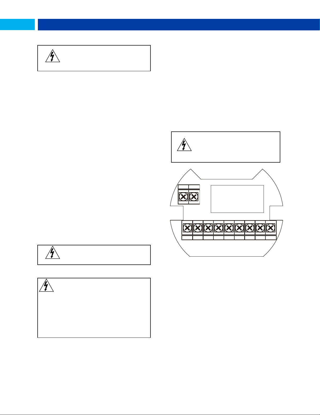
S+
Signal input positive terminal connection
S-
Signal input negative terminal connection
COM
DC power supply input return/negative, reset
contact closure common
RST
Contact closure reset pull-up to 1.8 VDC
P+
DC Power positive terminal connection
LP+
4-20 mA transmitter DC power positive terminal
connection.
LP-
4-20 mA transmitter regulated current output
terminal connection
OC1+
Open collector output 1 positive terminal
OC1-
Open collector output 1 negative terminal
OC2+
Open collector output 2 positive terminal
OC2-
Open collector output 2 negative terminal
WARNING
Observe all safety regulations. Electrical
wiring should be performed in accordance
with all agency requirements and
applicable national, state, and local codes
to prevent damage to the meter and ensure
personnel safety.
P+
C O M R S T
S+
S- O C 1+
O C 1-
O C 2+
O C 2-
L P+L P-
INSTALLATION
Wiring connectors are accessed by opening the enclosure.
To access electrical connectors, remove the 2 captive
screws, then disconnect the ribbon cable from the display
module and set the display module aside.
Unpacking
Remove the meter and conduit plug from box. Inspect the
packaging and contents for damage. Report damages, if
any, to the carrier. If any part is missing or the meter
malfunctions, please contact your supplier or the factory for
assistance.
Conduit/Stopping Plug
The PD6730 is provided with three ¾" NPT threaded conduit
openings and one IP68 rated ¾" NPT plastic conduit plug.
The conduit/stopping plug included has 1.29" wrenching flats
and a screwdriver slot.
Battery Activation Pull Tab
PD6730 models with battery or battery backup power will
include a battery activation pull-tab. This tab assures the
meter is not operational during shipment or storage, and is
located with the battery. Remove this tab during installation
of the meter.
Connections (continued)
Refer to Figure 1 for terminal positions.
Mounting
The PD6730 has two slotted mounting flanges that may be
used for pipe mounting or wall mounting. Alternatively, the
unit may be supported by the conduit using the conduit holes
provided.
Refer to Mounting Dimensions, page 40 for details.
Figure 1. Connector Board
Connections
Find Quality Products Online at: [email protected]
To access the connectors, remove the enclosure cover and
unscrew the two captive screws that fasten the display
module into the enclosure. Disconnect the ribbon cable and
remove the display module. Power and signal connections
are made to a barrier terminal connector in the base of the
enclosure.
www.GlobalTestSupply.com
8
Page 9
PD6730 Vantageview Pulse Input Rate/Totalizer Instruction Manual
F lo w m et er
(P u ls e O ut p ut )
P ow e r
S up p ly
C O M R ST
P+
S+ S-
IN P U T LE V E L
m V V I S O
F lo w m et er
(P u ls e O ut pu t )
P ow e r
S up p ly
C O M R ST
P+
S+ S-
IN P U T LE V E L
m V V IS O
F lo w m et er
(M a g ne ti c P ic ku p C oi l)
C OM
R ST
P+
S+ S-
IN P U T L E V EL
m V V ISO
+ 3. 0 V
1 00 k O hm
In te rn a l P u llu p
N P N
S E NS O R
C O M
R S T
P+
S+ S-
IN P U T LE V E L
m V V IS O
1 00 k O hm
In te rn a l P u ll- Do w n
P N P
S E NS O R
P ow e r
S up p ly
C O M
R S T
P+
S+ S-
IN P U T LE V E L
m V V IS O
+ 3. 0 V
1 00 k O hm
In te rn a l P u llu p
S W IT C H
C O N TA C T
C O M R S T
P+
S+ S-
IN P U T LE V E L
m V V IS O
P ow e r
S up p ly
C O M R S T
P+
S+ S-
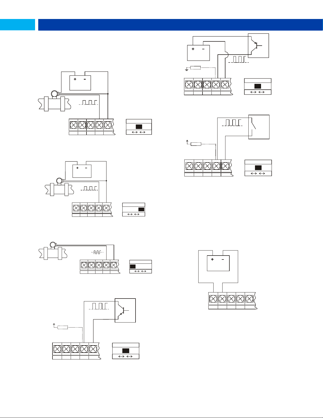
Input Signal Connections
Signal connections are made to a barrier terminal mounted
in the base of the enclosure. Input level and type are
configured using the slide switches on the bottom of the
display module as shown in the lower right of the following
figures.
Figure 2. Flowmeter Powered by External Supply
(Active)
Figure 3. Isolated Flowmeter Powered by External
Supply (ISO)
Figure 6. PNP Sensor with External Power (PNP)
Figure 7. Switch Contact Input (Reed)
DC Power Connection
Models configured for DC power are provided with a terminal
labeled P+ and are wired as shown in Figure 8. Models
configured for battery power may optionally be connected to
DC power and the battery will function as backup power when
DC is lost. The same power supply may be used to power
other circuits including a PNP-type sensor, however to
maintain input isolation, a separate power supply must be
used to power the isolated 4-20 mA transmitter as shown in
Figure 10 and/or to power the Opto-Isolated Flowmeter as
shown in Figure 3.
Figure 4. Self-Powered Magnetic Pickup Coil Flowmeter
(Coil)
Figure 8. DC Power Connections
Figure 5. NPN Open Collector Input (NPN)
Find Quality Products Online at: [email protected]
www.GlobalTestSupply.com
9
Page 10
PD6730 Vantageview Pulse Input Rate/Totalizer Instruction Manual
C O M R S T+
S+
S-
+ 3. 0 V
1 00 k O hm
In te rn a l P u llu p
L P- L P+
P ow e r
S up p ly
4 -2 0 m A I np u t
D ev ic e
Vantageview
D
AT
A
D
AT A DO
DO
DI
DI
GND
GND
RS-485 DEVICE
Vantageview
D
AT A D
AT A GND
GND
RS-485 DEVICE
D
AT A D
AT
A
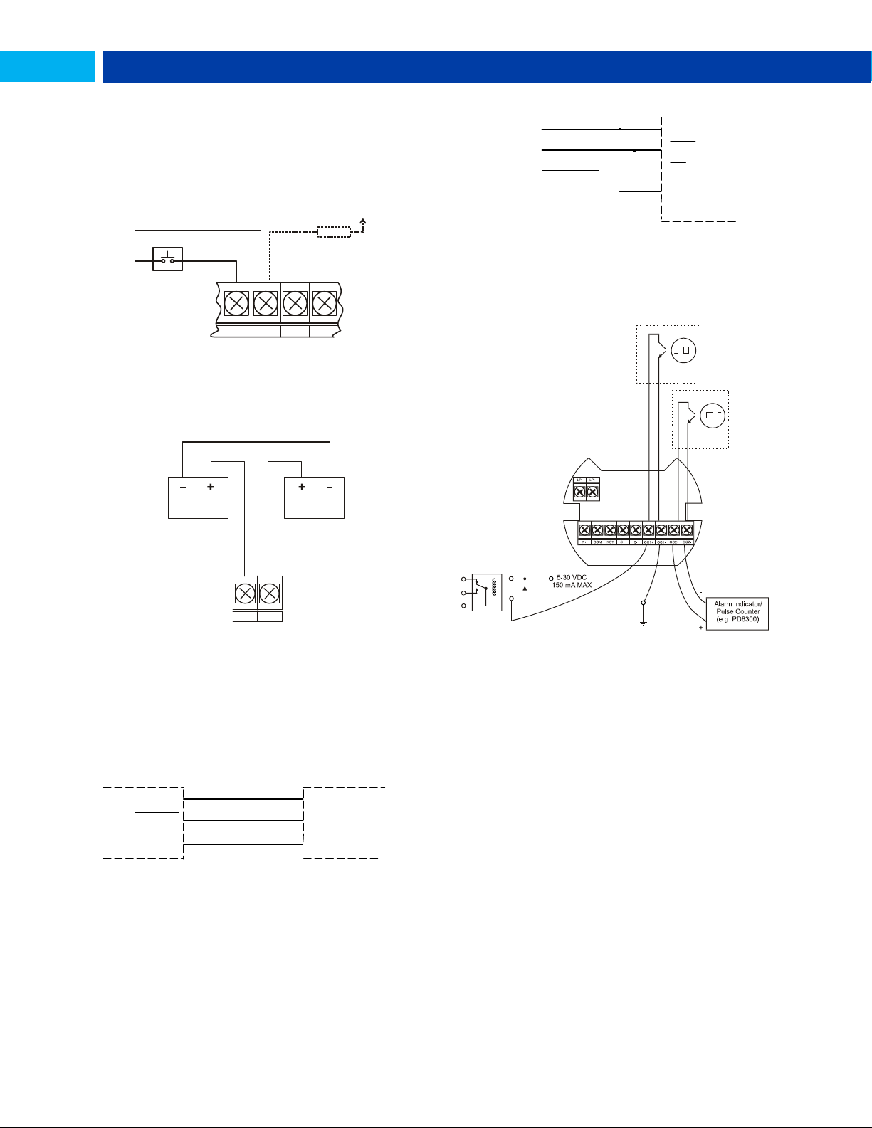
External Total Reset Connection
External total reset connections are made between RST and
COM. Connect to a contact closure source such as a relay or
a pushbutton as shown in Figure 9. Avoid extended contact
closure to preserve battery life. The total is reset when he
button is pressed. The meter will start to totalize immediately.
Holding down the button has no effect on the total.
Figure 9. Reset Connections
4-20 mA Transmitter Output Connections
Output connections are made to two terminals labeled LP+
and LP-. Connect to an input device such as a remote display
or chart recorder as shown in Figure 10.
Figure 12. RS-485 4 Wire Serial Connections
Open Collector Output Connections
Open collector output 1 and 2 connections are made to
terminals labeled OC1+ and OC1-, and OC2+ and OC2-.
Connect the alarm or pulse input device as shown in Figure
13.
Figure 10. 4-20 mA Output Connections
RS-485 Serial Connections
The meter may include an optional RS-485 two-wire serial
connection. The cabling used for an RS-485 serial
communications network should always be a high quality
cable such as Belden 8162 or Alpha 6203C. A two-wire
system requires two twisted pairs, and a four-wire system
requires three twisted pairs (the extra twisted pair is needed
for the signal ground).
Figure 11. RS-485 2 Wire Serial Connections
Figure 13. Open Collector Output Connections
10
Find Quality Products Online at: [email protected]
www.GlobalTestSupply.com
Page 11
PD6730 Vantageview Pulse Input Rate/Totalizer Instruction Manual
WARNING
Fire, explosion and bur ns may result if
not handled pr oper ly. Do not rechar ge,
shor t circuit , cr ush, disassemble, heat
above 1 0 0 °C (2 1 2 °F), inciner at e, or
expose cont ents to water .
Battery disposal should be in accordance
with applicable regulations, which vary by
location. In many locations trashing of used
batteries is forbidden and disposal is done
through local battery disposal facilities.
Spent batteries should be packaged in
such a way as to prevent short circuits
during handling and transport.
There is no need to recalibrate the meter for frequency
in Hz when first received from the factory.
The meter is factory calibrated for Hz prior to shipment.
The calibration equipment is certified to NIST standards.
SafeTouch Power Save Mode
SafeTouch buttons enter a power saving mode after three
minutes of inactivity. This mode is indicated by a pause
symbol ( ) appearing in the lower right of the display. Only
the MENU button is monitored in this mode. To activate the
SafeTouch buttons, press and hold the menu button for up
to five seconds. The display will read AWAKE, and the
SafeTouch buttons will be fully enabled.
SafeTouch Disabled Mode
When the cover is removed, the four mechanical buttons
located next to the sensors may be used. The sensors are
disabled when a mechanical button is pressed and will
automatically be re-enabled after 60 seconds of inactivity.
The SafeTouch power symbol ( ) will blink in the lower
right of the display if the buttons are disabled due to a
mechanical pushbutton being pressed.
IMPORTANT
SafeTouch buttons will not work if two or
more buttons are detected as being
pressed simultaneously. As a result, be
careful to avoid triggering multiple buttons
or reaching across one button location to
press another.
P
D
A
B
A
T
3
6
C
-
+
+
+
+
+
+
+
+
+
+
+
+
+
Battery Replacement
Battery-equipped models have a battery charge monitor.
When the battery is nearing the end of its capacity the screen
will periodically flash the message LO BATTERY and the BAT
indicator on the screen will flash. The recommended
replacement interval for models using the battery as a primary
power source is determined by the power and feature use, as
shown on page 4. The battery should be replaced when the
low battery indication is on the screen.
The total is backed up in non-volatile memory when the low
battery monitor is tripped. It is recommended that an updated
reading be manually backed up prior to changing out the
battery.
NOTICE: Battery may only be replaced with an original
Model PDABAT36C supplied by Precision Digital. Do not
recharge battery. Do not replace with used battery.
Remove cover and display module and disconnect
display module ribbon cable.
Carefully cut and remove the cable ties supplied for
shipping (if present).
Remove the spent battery and prepare it for disposal.
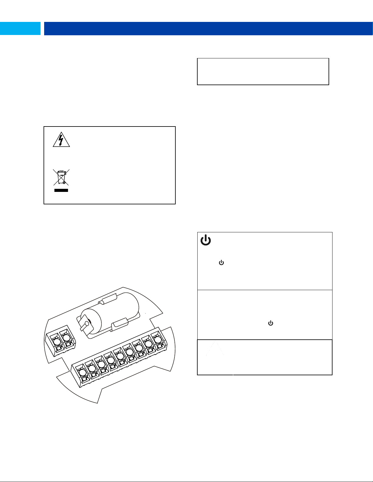
Install new PDABAT36C into battery clip with polarity as
shown in Figure 14.
Reconnect and fasten display module. Install enclosure
cover.
Resume operation.
SETUP AND PROGRAMMING
Overview
Setup and programming is done through the infrared
through-window SafeTouch buttons, or using the mechanical
buttons when uncovered. There are two slide switches
located on the display module. One is used to configure the
input and the other is to lock or unlock the SafeTouch
Buttons.
SafeTouch Buttons
This meter is equipped with four sensors that operate as
through-window buttons so that it can be programmed and
operated without removing the cover. These buttons can be
disabled for security by using the THRU-GLASS BUTTONS
switch and selecting the OFF setting. This switch is located
on the back of the removable electronics module.
SafeTouch Button Operation
To actuate a button, press and remove one finger to the
window directly over the marked button area. Remove finger
to at least 4 inches away from the window in between button
activations. SafeTouch and mechanical buttons may be held
to cycle through menus or digits in place of repeatedly
pushing a button.
Figure 14. Battery Orientation
Find Quality Products Online at: [email protected]
www.GlobalTestSupply.com
11
Page 12
PD6730 Vantageview Pulse Input Rate/Totalizer Instruction Manual
SafeTouch Button Equalize Delay
The SafeTouch buttons are designed to constantly
recalibrate for ambient conditions. When the cover position
is changed, the cover is removed, or an object is removed
that was placed over the front window, it may take a
moment for the SafeTouch buttons to recalibrate to the
change in conditions.
Allow up to 2 minutes for the SafeTouch buttons to
recalibrate to new conditions in these cases where the
cover position was changed, or the front window is being
unblocked.
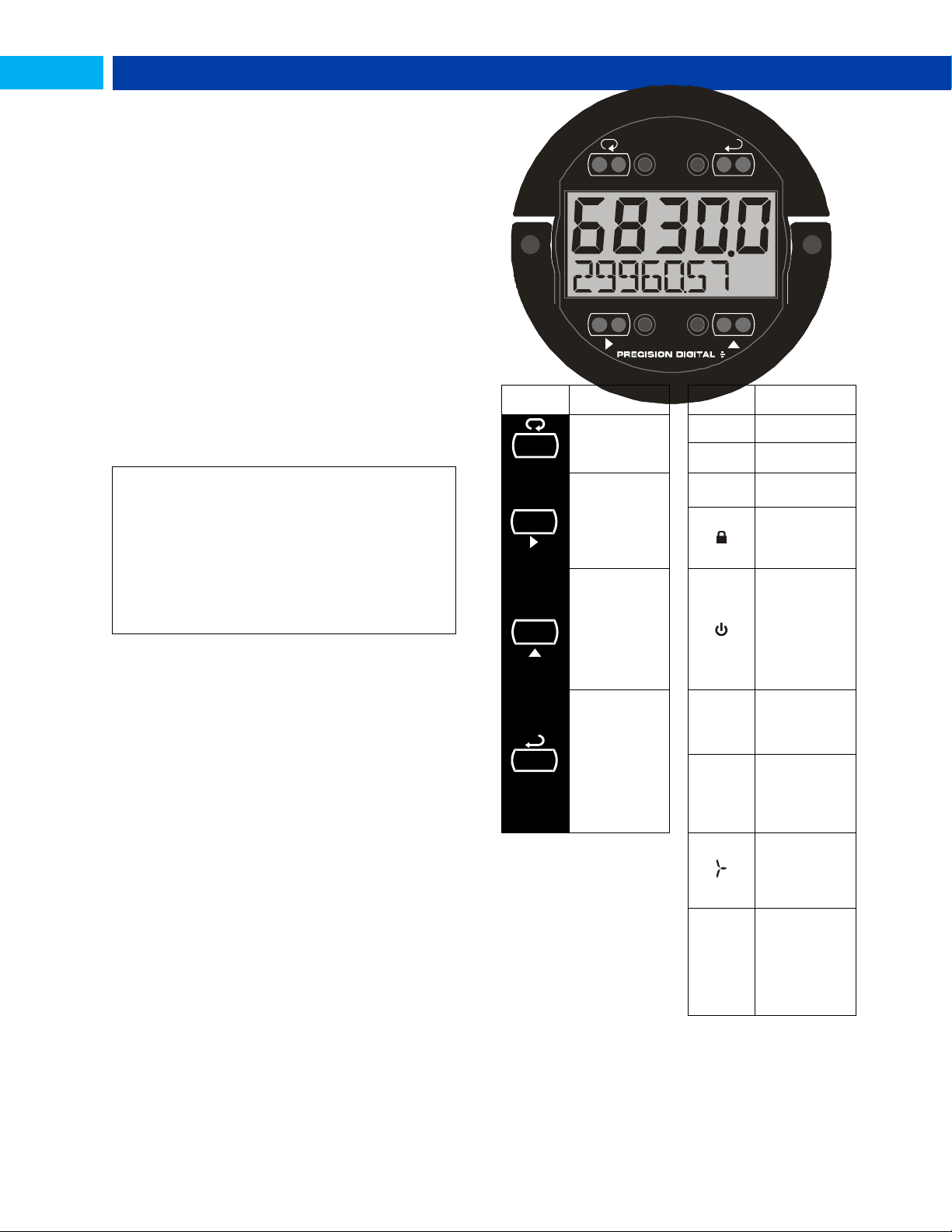
ENTER
DISPLAYRESET
MENU
Button
Symbol
Description
Symbol
Status
Menu/
SafeTouch
Awake
HI
High Alarm
LO
Low Alarm
Right
Arrow/Reset
SET
Total Alarm
Settings
Lockout
Password
Enabled
Up Arrow/
Display
SafeTouch
Power
Save/Disable.
Flashing:
Temporarily
Disabled Due
to Mechanical
Button
Enter/
Alarm
Acknowledge
T
Total Display
Flashing: Total
Overflow
Indication
GT
Grand Total
Display
Flashing: Total
Overflow
Indication
13 Digit Total
Overflow, 6
Most
Significant
Digits
BAT
Flashing: Low
Battery
Indicator
Steady:
Powered by
Battery
Backup
M E N U
ENTER
DISPLAY
RESET
SafeTouch Button Tips and Troubleshooting
The SafeTouch Buttons are designed to filter normal levels
of ambient interference and to protect against false
triggering, however it is recommended that the SafeTouch
Buttons be turned off (slide THRU-GLASS BUTTONS switch
to OFF) if there is an infrared interference source in line-ofsight to the display or if the buttons are not needed.
SafeTouch Button Tips:
To the extent possible, install the display facing away
from sunlight, windows, reflective objects and any
sources of infrared interference.
Keep the window clean.
Tighten the cover securely.
Use a password to prevent tampering.
If the cover has not been installed and secured
tightly, it may take a moment for the SafeTouch
buttons to properly self-calibrate when the cover is
tightened.
After all connections have been completed and verified,
connect the ribbon cable to the display module, fasten the
display module to the base, install enclosure cover, and then
apply power.
Buttons and Display
Find Quality Products Online at: [email protected]
12
www.GlobalTestSupply.com
Page 13
PD6730 Vantageview Pulse Input Rate/Totalizer Instruction Manual
Menu Button
Hold the Menu SafeTouch button when in power
save mode (display will show ) to awaken
SafeTouch buttons.
Press the Menu button to enter Programming Mode.
Press the Menu button during Programming Mode to
return to return to the previous menu selections.
Hold the Menu button for 1.5 seconds at any time to
exit Programming Mode and return to Run Mode.
Press and hold the Menu button for 3 seconds to
access the Advanced Features of the meter.
Right / Reset Button
Press the Right arrow button to move to the next
digit or decimal position during programming.
Press Right to go backward through most selection
menus.
Press Reset to reset the total, or values displayed in
the bottom display (grand total, max, or min). Press
Enter after Reset to confirm the reset.
Up / Display Button
Press Display when in Run mode to display the
grand total, again to display the maximum, and again
to display the minimum reading since last reset.
These displays will time out in 12 seconds, or press
Display until total is displayed in the lower display.
Press Enter to lock this display, and disable the 12
second time out.
Press the Up arrow button to scroll forward through
the menus, decimal point, or to increment the value
of a digit.
Enter Button
Press the Enter button to access a menu or to
accept a setting.
Press Enter to lock the grand total, maximum, or
minimum value on the lower display, and disable the
12 second time out.
Press Enter while the grand total, max, or min
reading is locked on the lower display to return to run
mode.
Press Enter to acknowledge alarm (if enabled).
Press Enter to lock display of grand total, Max or Min
readings (disables 10 second timeout).
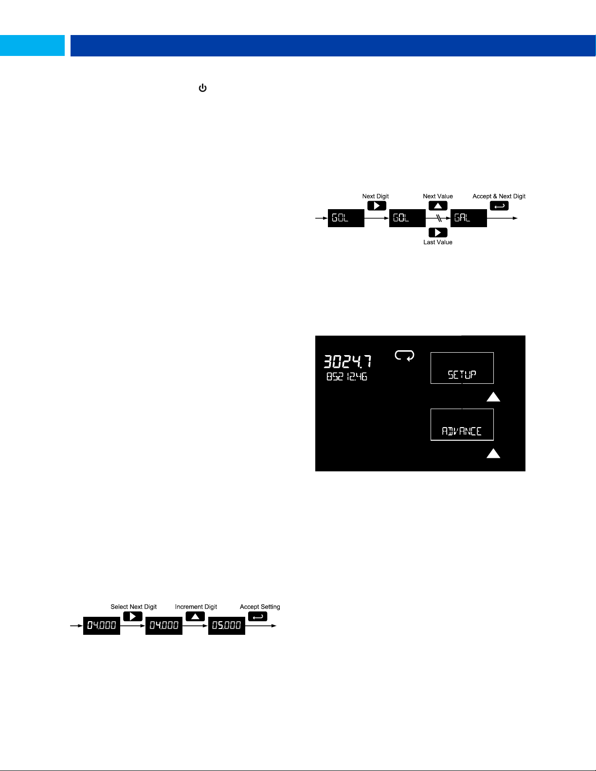
Setting Numeric Values
The numeric values are set using the Right and Up arrow
buttons. Press Right arrow to select next digit and Up arrow
to increment digit.
The digit being changed blinks.
Press the Enter button, at any time, to accept a setting or
Menu button to exit without saving changes.
The decimal point is set using the Right or Up arrow button
in the Setup, Decimal Point menu.
Setting Alphanumeric Labels (LABEL)
Fully alphanumeric values are set using the Right button to
select the digit, the Up and Right arrow buttons to select the
digit reading, and the Enter button to confirm and select the
next digit.
Menus using this entering method will display LABEL in the
upper display. After selecting the digit, and using the Up and
Right arrows to modify the digit, the display will read CHAR.
Using Enter to confirm the new digit will return the display to
reading LABEL.
The digit being changed blinks.
Press the Menu button to exit without saving changes.
Main Menu
The main menu separates the most commonly used
functions in the Setup menu, and more complex features in
the Advanced Features menu.
Press Menu button to enter Programming Mode then press
the Up arrow button to scroll through the main menu.
Press Menu, at any time, to return to the previous
menu selection. Press and hold the Menu button for 1.5
seconds at any time to return to Run Mode.
Changes to the settings are saved to memory only after
pressing Enter.
The display moves to the next menu every time a
setting is accepted by
pressing Enter.
13
Find Quality Products Online at: [email protected]
www.GlobalTestSupply.com
Page 14

PD6730 Vantageview Pulse Input Rate/Totalizer Instruction Manual
Display
Parameter
Action/Setting
SETUP
Setup
Enter Setup menu
Input
Input
Enter Input type
selection menu
Activ
Active
Set active input type
npn
NPN
Set NPN input type
pnp
PNP
Set PNP input type
Reed
Reed
Set reed switch input
type
COIl
Coil
Set coil input type
iso
Isolated
Set isolated input
type
ActlO
Active low
Set active input type
with low threshold
npnlO
NPN low
Set NPN input type
with low threshold
pnplO
PNP low
Set PNP input type
with low threshold
Factr
K-factor
Enter the K-Factor
menu
FUNIT
K-factor units
Enter the K-Factor
units
P/GAL
Pulses/gallon
Set K-factor in
pulses per gallon
P/L
Pulses/liter
Set K-factor in
pulses per liter
P/IGAL
Pulses/imp
gallon
Set K-factor in
pulses per imperial
gallon
P/M3
Pulses/meter3
Set K-factor in
pulses per meter
cubed
P/BBL
Pulses/barrel
Set K-factor in
pulses per barrel
P/BUSH
Pulses/bushel
Set K-factor in
pulses per bushel
P/cuyD
Pulses/cubic
yard
Set K-factor in pulses
per cubic yard
P/cuFt
Pulses/cubic
feet
Set K-factor in
pulses per cubic foot
P/cuIn
Pulses/cubic
inch
Set K-factor in pulses
per cubic inch
P/LiBBL
Pulses/liquid
barrel
Set K-factor in
pulses per liquid
barrel
P/BBBL
Pulses/beer
barrels
Set K-factor in
pulses per beer
barrel
Display
Parameter
Action/Setting
P/HECtL
Pulses/hectolit
er
Set K-factor in
pulses per hectoliter
P/CUST
Pulses/custom
Set K-factor custom
unit
Dec.pT
K-factor
decimal point
Set the number of
decimal points in the
K-factor
FAcTR
K-factor value
Set the K-factor for
custom units
Unit``s
Units
Select standard
units or custom
unit/tag
TbASE
Rate time
base
Enter the Time Base
menu
seC
Second
Units per second
min
Minute
Units per minute
hour
Hour
Units per hour
day
Day
Units per day
RateU
Rate units
Select rate display
units
GAL
Gallons
Set units as gallons
L
Liters
Set units as liters
IGAL
Imperial
gallons
Set units as imperial
gallons
M3
Meters cubed
Set units as cubic
meters
BBL
Barrels
Set units as barrels
BUSH
Bushels
Set units as bushels
cuyD
Cubic yards
Set units as cubic
yards
cuFt
Cubic feet
Set units as cubic
feet
cuIn
Cubic inches
Set units as cubic
inches
LiBBL
Liquid barrels
Set units as liquid
barrels
BBBL
Beer barrels
Set units as beer
barrels
HECtL
Hectoliter
Set units as
hectoliters
CUSt
Custom unit
Use a custom unit
USER
User
Set a custom unit
LABEL
Label
Select a custom unit
label character
CHAR
Character
Set a character in a
custom unit label
ratCF
Rate
conversion
factor
Enter the Rate
Conversion Factor
menu
Tot U
Total units
Select total display
units
Setup Menu Display Functions &
Messages
The meter displays various functions and messages during
setup, programming, and operation. The following table
shows the main menu functions and messages in the order
they appear in the menu.
Find Quality Products Online at: [email protected]
www.GlobalTestSupply.com
14
Page 15

PD6730 Vantageview Pulse Input Rate/Totalizer Instruction Manual
Display
Parameter
Action/Setting
Nmult
Total multiplier
Select the total units
multiplier
X1
x1 (no
multiplier)
Select no multiplier
X100 h
x100 (h)
Select x100
multiplier with h unit
prefix
X1000 k
x1000 (k)
Select x1,000
multiplier with k unit
prefix
X1.0e6 M
x1.0*106 (M)
Select x1,000,000
multiplier with M
prefix
TotCF
Total
conversion
factor
Enter the Total
Conversion Factor
menu
GToTU
Grand total
units
Select grand total
display units
Nmult
Grand total
multiplier
Select the grand
total units multiplier
GrtCF
Grand total
conversion
factor
Enter the Grand
Total Conversion
Factor menu for
custom units
Dec..pt
Decimal point
Enter Decimal Point
menu
Rate
Rate decimal
Set rate display
decimal point
total
Total decimal
Set total display
decimal point
Grtot
Grant total
Set grand total
display decimal point
Dsply
Display
Set the function of
the top and bottom
displays
tOp
Top
Set the function of
the top display
Rate
Rate
Display rate
Total
Total
Display total
BOtnm
Bottom
Set the function of
the bottom display
Total
Total
Display total
TOgle
Toggle
Toggle between the
values shown in the
bottom display
TOTAL+U
Total & units
Display total & units
TOT+TAG
Total & Tag
Display the total and
custom tag
T+U+RU
Total & units &
rate units
Display the total,
total units, and rate
units
Grtot
Grand total
Display grand total
GrTOT+U
Grand total &
units
Display grand total
and units
Display
Parameter
Action/Setting
GT+TAG
Grand total &
tag
Display the grand
total and custom tag
GT+U+RU
Grand total &
units & rate
units
Display the grand
total, grand total
units, and rate units
rate
Rate
Display the rate
RaTe+TU
Rate & total
units
Display the rate and
total units
RaTe+RU
Rate & units
Display the rate and
rate units
RAT+TAG
Rate & tag
Display the rate and
custom tag
RUnit
Rate unit
Display the rate
units
TotUn
Total units
Display the total
units
TAG
Custom tag
Enter the custom tag
to be displayed
Off
Off
Turn off the bottom
display
Tag TIME
Tag Time
Set time to display
custom tag
Unit TIME
Unit Time
Set time to display
lower display unit
Rate TIME
Rate Unit
Time
Set time to display
rate unit
Find Quality Products Online at: [email protected]
www.GlobalTestSupply.com
15
Page 16
PD6730 Vantageview Pulse Input Rate/Totalizer Instruction Manual
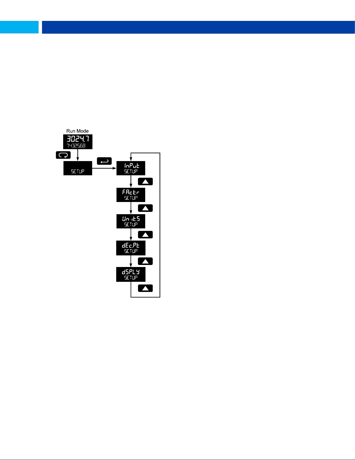
Setting Up the Meter (SETUP)
The Setup menu is used to select:
1. Input type selection (INPuT)
2. K-factor number and units (FActr)
3. Display rate, total, and grand total units (Units)
4. Rate and total decimal point position (dec.pt)
5. Select what will appear on the lower display
(DSPLY)
Press the Enter button to access any menu or press Up
arrow button to scroll through choices. Press the Menu
button to back out of a menu, or hold the Menu button to exit
at any time.
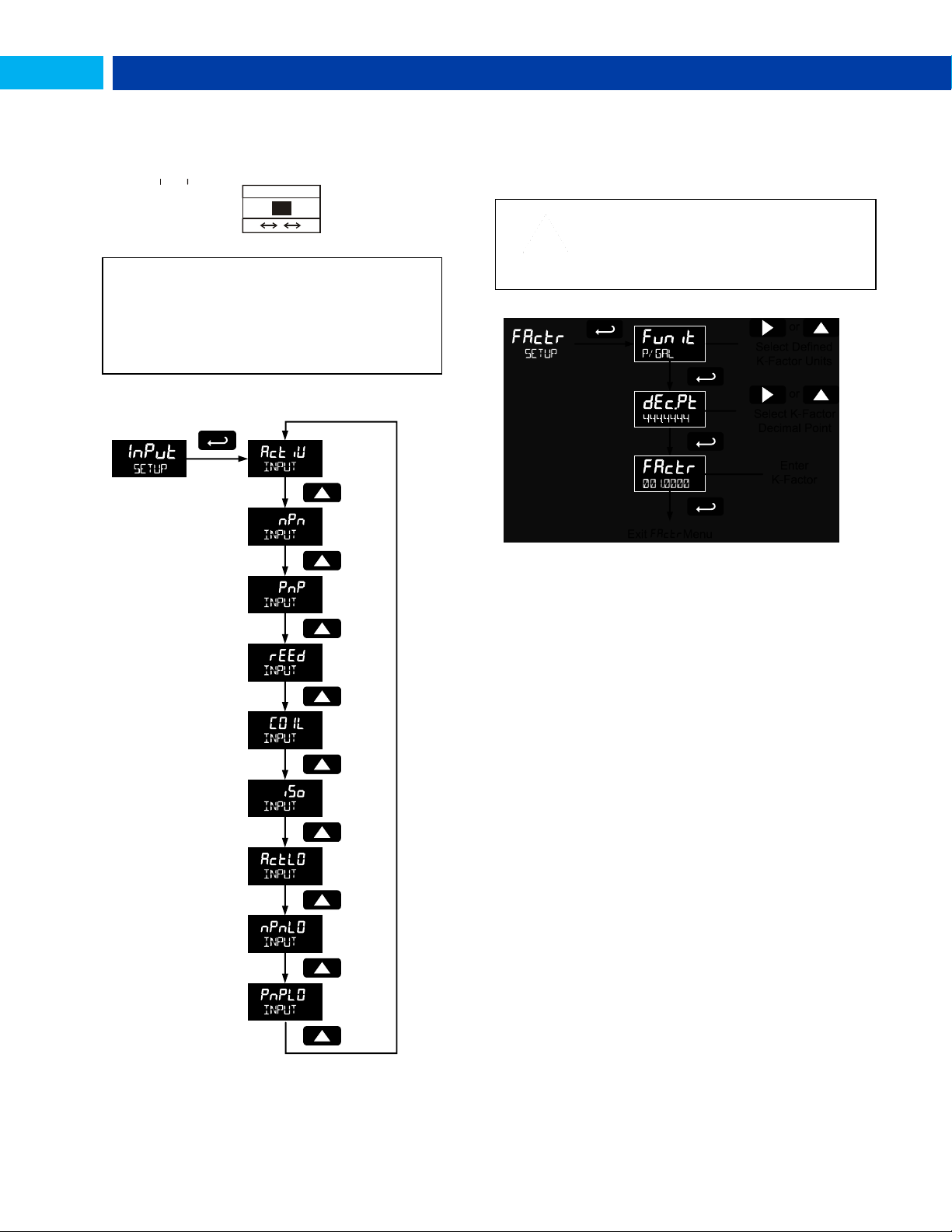
Selecting Input Type (Input)
Seven input types may be set. See Rate Input specifications
on page 5 for electrical specifications of the inputs.
The following input types may be selected:
Active (activ)
External power supply driven pulse inputs
NPN (NPN)
Internal pull-up resistor on S+ for NPN inputs
PNP (PNP)
Internal pull-down resistor on S+ for PNP inputs
Reed (reed)
Internal pull-up resistor on S+ for switch inputs
Coil (COIL)
Magnetic coil flowmeter inputs (input selector switch
must be set to mV)
Isolated active input (iso)
External power supply driven isolated pulse inputs (input
selector switch must be set to ISO)
Active with low threshold (acTLO)
External power supply driven pulse inputs with a low
threshold
NPN with low threshold (NPNLO)
Internal 3 V pull-up resistor on S+ for NPN inputs with a
low threshold
PNP with low threshold (PNPLO)
Internal pull-down resistor on S+ for PNP inputs with a
low threshold
16
Find Quality Products Online at: [email protected]
www.GlobalTestSupply.com
Page 17
PD6730 Vantageview Pulse Input Rate/Totalizer Instruction Manual
See Rate Input specifications on page 5 for electrical
specifications of the inputs.
See Input Signal Connections on page 9 for details on
wiring the input types.
IMPORTANT
Performing a k-factor operation will override
any scaling or calibration programming.
Refer to
Scaling & Calibration (SCALCAL) on page 28
for more information on these programming
methods.
+ 3. 0 V
1 00 k O hm
In te rn a l P u llu p
N P N
S E NS O R
C O M
R S T
P+
S+ S-
IN P U T LE V E L
m V V IS O
Input Level Selection Switch
In addition to programming the Input parameter, the input
selector switch shown below must also be set. Input voltage
level selections include mV, V and isolated voltage level
inputs.
information with the device. Enter the K-Factor (Factr)
menu and select the units defined with the k-factor (example:
pulses/gal), the decimal point with highest resolution
possible, and program the K-Factor value. The meter will
automatically calculate the flow rate using the K-Factor and
the units and time base selected.
K-Factor Units (FuNiT)
Select the units defined with the k-factor (example:
pulses/gal). This is usually provided by the flowmeter
manufacturer. This does not set the rate display units, and
only relates to entering the K-factor. To set or change the
rate display units, see Setting the Rate Display Units (rateU)
on page 19
The K-factor unit may be a custom unit (CUST).
Automatic unit conversions are not performed when the K-
factor unit is set to custom. See page 20 for information on
the automatic unit conversion feature.
K-Factor Decimal Point (dec.pt)
Set the number of decimal places necessary to enter the Kfactor value. The decimal point may be set with up to six
decimal places or with no decimal point at all.
Pressing the Right arrow moves the decimal point one place
to the right (including no decimal point). Pressing the Up
arrow moves the decimal point one place to the left.
K-Factor Value (factr)
Enter the K-factor value. This value is entered in Pulses/Unit
as defined by the K-Factor Units parameter. Most flowmeter
manufacturers provide this information with the device.
Entering the K-Factor (Factr)
The meter may be scaled using the K-factor, or conversion
Find Quality Products Online at: [email protected]
factor, function. Most flowmeter manufacturers provide this
www.GlobalTestSupply.com
17
Page 18
PD6730 Vantageview Pulse Input Rate/Totalizer Instruction Manual
Important Programming Note:
The units selected in this menu are the desired display
units only. The units defined by the k-factor of a flow
meter are entered in the K-Factor menu as part of the
Factor Unit menu programming. See K-Factor Units
(FuNiT) on page 17 for details.
This allows the display units to be different than the units
defined by the flow meter, or be changed easily after
initial programming. Unit conversions for rates and totals
are performed automatically by the meter. See Automatic
Unit Conversions on page 20 for details.
GAL
Gallons
Set units as gallons
L
Liters
Set units as liters
IGAL
Imperial gallons
Set units as imperial
gallons
M3
Meters cubed
Set units as cubic meters
BBL
Barrels
Set units as barrels
BUSH
Bushels
Set units as bushels
cuyD
Cubic yards
Set units as cubic yards
cuFt
Cubic feet
Set units as cubic feet
cuIn
Cubic inches
Set units as cubic inches
LiBBL
Liquid barrels
Set units as liquid barrels
BBBL
Beer barrels
Set units as beer barrels
HECtL
Hectoliter
Set units as hectoliters
CUSt
Custom unit
Use a custom unit
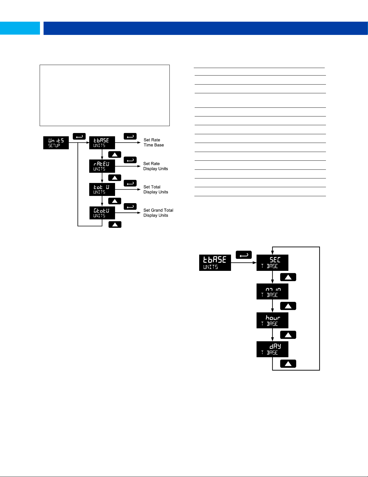
Display Units (Units)
The Units menu is used to select the display rate units and
time (example: Gal/s) and the display units for total and
grand total.
The following units may be selected as the base units for
rate, total, and grand total. Time base for rate and a
multiplier for total and grand total units may also be selected
separately.
Units Unit Description
Setting the Time Base (tbase)
The meter calculates rate based on rate time base and rate
display units. The time base is the unit of time used to
calculate the rate, and can be set as units per second,
minute, hour, or day.
Press the Enter button, at any time, to accept a setting or
Menu button to exit without saving changes.
Find Quality Products Online at: [email protected]
www.GlobalTestSupply.com
18
Page 19
PD6730 Vantageview Pulse Input Rate/Totalizer Instruction Manual
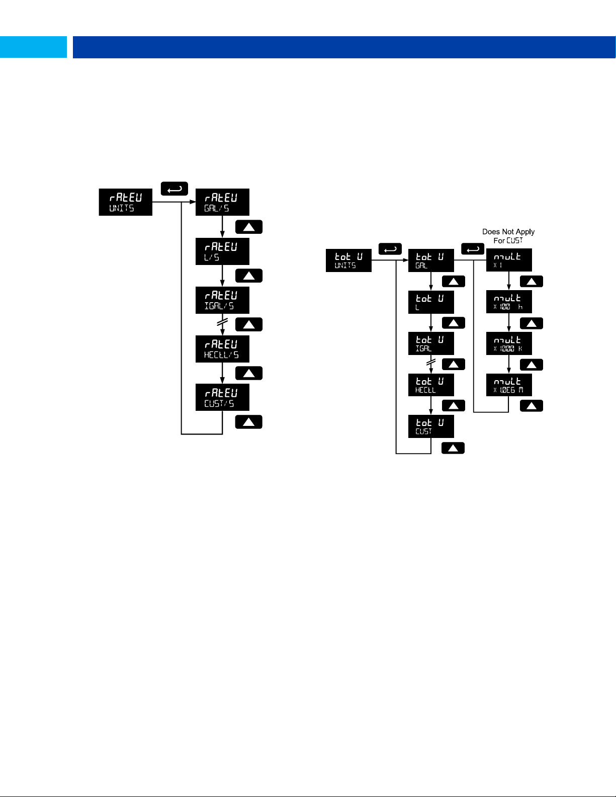
Setting the Rate Display Units (rateU)
Rate is displayed in terms of a unit of volume, and a time
base. The unit selected will be used with the time base to
establish the rate unit (example: GAL/S when Units is GAL,
and time base is seconds).
The custom unit selection (CUST) will require the custom unit
to be entered by the user. See Custom Units Rate
Conversion Factor on page 20.
Press the Enter button, at any time, to accept a setting or
Menu button to exit without saving changes.
Total Units (tot U)
This menu is used to select the display units for the total.
The base unit and a multiplier prefix are selected. If total and
units are selected to display, the multiplier prefix will appear
before the total unit (example: MGAL, kL).
Multipliers will convert the total for 1, 100, 1000, or 1 million
units. The meter will calculate the total appropriately for
display with the programmed multiplier and units.
A custom unit may be selected (CUST), and no multiplier
menu will be required. In this case, use the total conversion
factor as defined in Custom Units Total Conversion Factor
on page 21.
Press the Enter button, at any time, to accept a setting or
Menu button to exit without saving changes.
19
Find Quality Products Online at: [email protected]
www.GlobalTestSupply.com
Page 20
PD6730 Vantageview Pulse Input Rate/Totalizer Instruction Manual
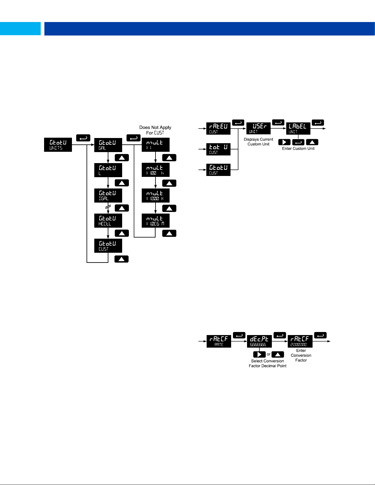
Grand Total Units (GtotU)
This menu is used to select the display units for the grand
total. The base unit and a multiplier prefix are selected. If
grand total and units are selected to display, the multiplier
prefix will appear before the total unit (example: MGAL, kL).
Multipliers will convert the total for 1, 100, 1000, or 1 million
units. The meter will calculate the total appropriately for
display with the programmed multiplier and units.
A custom unit may be selected (CUST), and no multiplier
menu will be required. In this case, use the grand total
conversion factor as defined in Custom Units Grand Total
Conversion Factor (GrtCF) on page 21.
Press the Enter button, at any time, to accept a setting or
Menu button to exit without saving changes.
Automatic Unit Conversions
When switching from any standard unit of rate, total, or
grand total to any other standard unit, automatic unit
conversions are performed by the meter.
No unit conversions will be performed when the K-Factor
Units (FuNiT) menu is set to custom (CUST).
A total or grand total unit conversion will automatically
change the displayed total and grand total to the equivalent
volume of the newly selected unit.
Custom Units Entry (USER)
When a custom unit is selected for rate, total, or grand total,
a User menu allows for entry of the custom unit.
Any 5-digit 14-segment unit may be entered for a custom
rate unit (example: mL).
Any 7-digit 14-segment unit may be entered for a custom
total or grand total unit (examples: GALLONS, BOTTLES,
DRUMS).
When selected for total or grand total, a custom unit will not
allow a multiplier prefix. A custom total or grand total unit will
allow a total or grand total conversion factor to be entered to
define the unit. See Custom Units Total Conversion Factor
on page 21 for details.
Fully alphanumeric values are set using the Right button to
select the digit to be changed. Press the Up button to begin
editing the digit, then the Up and Right arrow buttons to
select the next or previous alphanumeric character. Press
the Enter button to confirm and select the next digit to
change.
For details on setting alphanumeric labels, refer to Setting
Alphanumeric Labels (LABEL) on page 13.
Press Menu button to exit this menu without saving
changes.
Custom Units Rate Conversion Factor
(ratCF)
The rate conversion factor is only used when the Units for
rate have been set to custom (CUST). This menu will not
appear if standard display units are selected for the rate unit.
Rate Conversion Factor is used to convert to a custom unit
of rate display. For example, to display rate as quantity of
2.5 gallon containers when the K-Factor units are set to
gallons, enter a conversion factor of 2.500.
Press the Enter button, at any time, to accept a setting or
Menu button to exit without saving changes.
20
Find Quality Products Online at: [email protected]
www.GlobalTestSupply.com
Page 21
PD6730 Vantageview Pulse Input Rate/Totalizer Instruction Manual
1. Total
2. Alternating total and
total units
3. Alternating total and
custom tag
4. Alternating total, total
units, and rate units
5. Grand total
6. Alternating grand total
and
grand total units
7. Alternating grand total
and custom tag
8. Alternating grant total,
grand total units, and
rate units
9. Rate
10. Alternating rate and
total units
11. Alternating rate and
rate units
12. Alternating rate and
custom tag
13. Rate units
14. Total units
15. Custom tag
16. Off (blank)
Custom Units Total Conversion Factor
(totCF)
The total conversion factor is only used when the Units for
total have been set to custom (CUST). This menu will not
appear if standard display units are selected for total.
Total Conversion Factor is used to convert to a custom unit
of total display. For example, to display total as quantity of
2.5 gallon containers when the K-Factor units are set to
gallons, enter a conversion factor of 2.500.
Press the Enter button, at any time, to accept a setting or
Menu button to exit without saving changes.
Custom Units Grand Total Conversion
Factor (GrtCF)
The grand total conversion factor is only used when the
Units for grand total have been set to custom (CUST). This
menu will not appear if standard display units are selected
for grand total.
Grand Total Conversion Factor is used to convert to a
custom unit of total display. For example, to display grand
total as quantity of 2.5 gallon containers when K-Factor units
are set to gallons, enter a conversion factor of 2.500.
Press the Enter button, at any time, to accept a setting or
Menu button to exit without saving changes.
Configuring the Display (Dsply)
The top and bottom displays can be independently
programmed to display selected information.
Top Display (TOp)
The top display can be programmed to display rate or total.
When displaying total, the top display will only show the 5
least significant digits, with no overflow display, for a total
from 0 to 99999. The total rolls over at 99999 to 0 when on
the top display. For a full 7-digit total with 13-digit total
overflow display function, use the bottom display for total.
Bottom Display (bOtnm)
The bottom display can be programmed to display the
following information.
Setting the Decimal Point (dec.PT)
Rate decimal point may be set with up to four decimal places
or with no decimal point at all. Total decimal point may be
set with up to six decimal places or with no decimal point at
all. Grand total decimal point may be set with up to six
decimal places or with no decimal point at all. Rate decimal,
total decimal, and grand total decimal are programmed
individually.
Pressing the Right arrow moves the decimal point one place
to the right (including no decimal point). Pressing the Up
arrow moves the decimal point one place to the left.
Find Quality Products Online at: [email protected]
www.GlobalTestSupply.com
21
Page 22
PD6730 Vantageview Pulse Input Rate/Totalizer Instruction Manual
Custom Tag (TAG)
When the bottom display selected includes a custom tag, a
User menu will then allow a custom tag to be programmed.
Any 7-digit 14-segment label may be entered for a custom
tag (examples: RATe,
LINE 3, WaTER).
Fully alphanumeric values are set using the Right button to
select the digit, the Up and Right arrow buttons to select the
digit reading, and the Enter button to confirm and select the
next digit.
For details on setting alphanumeric labels, refer to Setting
Alphanumeric Labels (LABEL) on page 13.
Setting the Toggle Time (TIME)
If the bottom display is programmed to toggle (TOGLE), the
meter will prompt for a toggle time. In addition, it may require
a tag be entered, as shown in the example below.
Enter the time in seconds for the unit or tag to display in the
bottom window every 10 seconds. The unit may be
programmed to display for 1 to 5 seconds.
Press the Enter button, at any time, to accept a setting or
Menu button to exit without saving changes.
Advanced Features Menu
To simplify the setup process, functions not needed for most
applications are located in the Advanced Features menu.
Access the Advanced features menu by pressing Enter at
the Advance menu in the Main Menu defined on page 13.
The Advanced menu is used to select:
1. Open collector output configuration (OUTPUT)
2. Analog output configuration (A OUT)
3. Gate function for low speed inputs (GATE)
4. Set the input filter (FILTER)
5. Set low flow cutoff (CUTOFF)
6. Scale or live calibrate the meter and override k-
factor (SCALCAL)
7. Select method of total and grand total reset (T
RESET)
8. Set passwords (PASSWRD)
9. Reconfigure the Main menu structure (CUSTOM)
10. Enter the System menu for meter settings and
data logging (SYSTEM)
11. Configure serial communication settings (COMM) – if
applicable
12. Enter low-power Standby Mode (STANDBY) on
battery powered models
Advanced menus A OUT displayed only for meters with the
analog output option, COMM displayed only for meters with the
serial communications option, and STANDBY only for meters
with battery or battery backup power.
Press the Enter button to access any menu or press Up
arrow button to scroll through choices. Press the Menu
button to back out of a menu, or hold the Menu button to exit
at any time.
22
Find Quality Products Online at: [email protected]
www.GlobalTestSupply.com
Page 23

PD6730 Vantageview Pulse Input Rate/Totalizer Instruction Manual
Display
Parameter
Action/Setting
ADVANCE
Advanced
Enter Advanced menu
OUTPUT
Output
Setup open collector
outputs Out 1 and Out 2
OUT 1
Output 1
Assign function of
open collector output 1
OUT 2
Output 2
Assign function of
open collector output 2
PuLSE
Pulse
Set Out 1 or Out 2 for
pulse output mode
rate
Rate
Assign pulse output to
rate
total
Total
Assign pulse output to
total
Grtot
Grand total
Assign pulse output to
grand total
dec.pt
Decimal point
Set K-factor decimal
point
count
Count
Set K-factor
Retr
Retransmit
Assign pulse output to
retransmit
quad
Quadrature
Assign pulse output to
quadrature
Test
Test
Assign pulse output to
test mode
ALrnm
Alarm
Assign Out 1 or Out 2
for alarm output mode
rate
Rate
Assign alarm output to
rate
Set
Set point
Set rate alarm set point
reset
Reset point
Set rate alarm reset
point
total
Total
Assign alarm output to
total
Grtot
Grand total
Assign alarm output to
grand total
Set
Set point
Set total or grand total
alarm set point
On
On
Set output to on state
Off
Off
Set output to off state
Tnmer
Timer
Set Out 1 or Out 2 for
timed pulse output
mode
Start
Start
Activate timed pulse
output
Delay
Delay
Set the time of one
period (seconds)
On
On
Set the active low
pulse width
OFF
Off
Set Out 1 or Out 2 as
off
A OUT
Analog
Output
Enter Analog Output
menu
Rate
Rate output
Set rate as output
variable
total
Total output
Set total as output
variable
Display
Parameter
Action/Setting
Grtot
Grand total
output
Set grand total as
output variable
Dsp 1
Display 1
Output display 1 value
OUt 1
Output 1
Output 1 value
Dsp 2
Display 2
Output display 2 value
OUt 2
Output 2
Output 2 value
Save?
Save
Save entered analog
parameters
dsabl
Disable
Turn off the analog
output
GATE
Gate
Enter Gate menu
LO
Low gate
Set Low Gate
HI
High gate
Set High Gate
FILTER
Filter
Enter Filter menu
HI
High speed
filter
Set high speed filter
nmed
Medium
speed filter
Set medium speed
filter
LO
Low speed
filter
Set low speed filter
CUTOFF
Low-flow
cutoff
Enter Low-Low Cutoff
menu
SCALCAL
Scale &
calibrate
Enter the Scale &
Calibrate menu to
program without using
a k-factor
sCalE
Scale
Enter the Scale menu
Cal
Calibrate
Enter the Calibrate
menu
Undo?
KFACTOR
Undo K-factor
Undo the K-Factor
input programming
Undo?
SCALCAL
Undo scaling
& calibration
Undo the scaling and
calibration input
programming
No?
No
Do not undo other
programming
Yes?
Yes
Undo other
programming
Nopts
Number of
points
Enter the number of
scaling or calibration
points
Inp 1
Input 1
Calibrate or scale input
1 value
Dsp 1
Display 1
Program display 1
value
Inp 2
Input 2
Calibrate or scale input
2 value
DsP 2
Display 2
Program display 2
value
Save?
Save
Save entered
calibration or scale
parameters
T RESET
Total reset
Enter the Total Reset
menu
T rST
Total reset
Select the Total Reset
method
man
Manual
Manual total reset
Enabl
Enable
Enable manual reset
dsabl
Disable
Disable manual reset
Auto
Automatic
Automatic total reset
Advanced Features Menu & Display
Messages
The following table shows the Advanced features menu
functions and messages in the order they appear in the menu.
Find Quality Products Online at: [email protected]
www.GlobalTestSupply.com
23
Page 24

PD6730 Vantageview Pulse Input Rate/Totalizer Instruction Manual
Display
Parameter
Action/Setting
T DELAY
Time delay
Automatic reset time
delay
time
Total Reset
Time
Enter the time of day
to reset the total
hh.mm (Default: 00.00
midnight)
Set
CLOCK
Set Clock
Message indicates
that the clock must be
set. Go to Advance –
System – Set Time
GTrST
Grand total
reset
Select the Grand
Total Reset method
PASSWRD
Password
Enter the Password
menu
Pass
Password
Program password to
lock meter parameters
Pass T
Password
total
Program password to
prevent total reset
Pass GT
Password
grand total
Enter password to
permanently lock out
grand total related
parameters and reset
UnLOC
Unlock
Password has been
unlocked
LOCd
Lock
Password has been
locked
UNLOCKD
Unlocked
Program password to
lock meter
LOCKED
Locked
Enter password to
unlock meter
CUSTOM
Custom
Enter Custom menu
POS 1
Position 1
Set menu position 1
(1-8)
POS 8
Position 8
Set menu position 8
SYSTEM
System
Enter System menu
SETTIME
Set time
Set real-time clock
date and time
YEAR
Year
Set the year
MONTH
Month
Set the month
01
January
Set month as January
02
February
Set month as
February
03
March
Set month as March
04
April
Set month as April
05
May
Set month as May
06
June
Set month as June
07
July
Set month as July
08
August
Set month as August
09
September
Set month as
September
10
October
Set month as October
11
November
Set month as
November
12
December
Set month as
December
DAY
Day
Set the day
TIME
Time
Set the hour & minute
DATALOG
Data log
Enter Data Log menu
LOGTIME
Log time
Set daily data log
times
Display
Parameter
Action/Setting
LOG 1
Log 1
Set first daily log time
(1-4)
DsAbL
Disable
Disable log number
INTERVL
Interval
Set interval log time
STArT
Start
Begin interval logging
LOGVIEW
Log view
View data log
ALL
LOGVIEW
All log view
View all data log
points
LOG NUM
Log number
Go to specific log
number
ALL ERASE
All erase
Erase all logs
Erase?
Erase?
Confirm to erase all
logs
BAKLITE
Backlight
Enable or disable
backlight
DsabL
Disable
Disable backlight
EnAbL
Enable
Enable backlight
AO CAL
Analog output
calibration
Enter Analog Output
Calibration menu
BACKUP
Backup
Enter Backup menu
SAvE?
Save?
Save current
parameters to backup
restore
LOad?
Load?
Load parameters from
backup restore
DEFLT
Default
Restore factory
default parameter
settings
RESET
DFALTS?
Reset
defaults
Confirm factory reset
Bat syM
Battery
symbol
Enter Battery Symbol
menu
DsabL
Disable
Disable battery
backup symbol
EnAbL
Enable
Enable battery backup
symbol
INFO
Info
Enter Info menu
SOFT
Software
Display software ID
number
ver
Version
Display software
version number
nmodL
Model
Display model number
COMM
Communicati
ons
Enter
Communications
menu
nmbus
Modbus
Enter Modbus
communications
menu
SlvID
Slave ID
Set Modbus slave ID
BaUd
Baud rate
Set baud rate
Tdely
Transmit
delay
Set transmit delay
time
Party
Parity
Set parity and stop
bits
STANDBY
Standby
Enter standby mode
(battery powered only)
Yes?
Yes
Confirm standby
mode
Find Quality Products Online at: [email protected]
www.GlobalTestSupply.com
24
Page 25
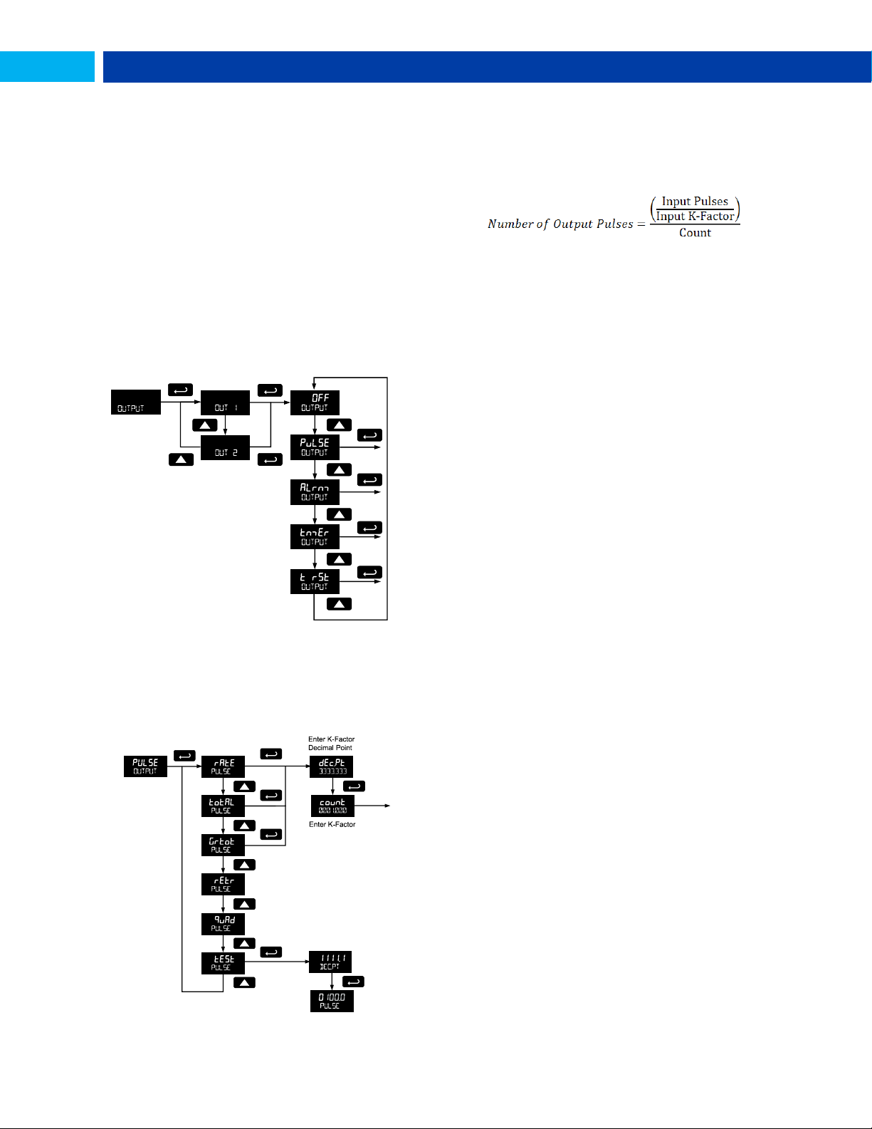
PD6730 Vantageview Pulse Input Rate/Totalizer Instruction Manual
Open Collector Outputs (OUTPUT)
The meter is equipped with two NPN open collector outputs
that may be set up for pulse outputs, alarms, timed pulses,
or turned off.
Pulse outputs are based on K-factor, total or grand total
counts, or one-for-one retransmit for input pulses. Both
outputs may be used to generate a quadrature output based
on any pulse menu output type. An output test mode is also
selectable to generate pulses at a constant programmable
frequency.
Alarms are available based on the rate, total, or grand total.
The alarm status will show on the display even if the output
is not wired. The outputs may also be forced on or off.
A timed pulse output generates constant pulses at a
specified frequency and on time.
A total reset output generates a pulse whenever the selected
total is reset, total or grand total, regardless of the reset
method used. The On time is programmable between 0.10
and 99,999.99 sec.
The output may be disabled by selecting Off.
Output 1 and 2 Setup (OUT 1, OUT 2)
The function of open collector output 1 and 2 is configured
using the Off, Pulse, Alarm, and Timer menus detailed
below.
Pulse Output (PUlse)
Pulse outputs may be assigned to rate, total, grand total,
retransmit, quadrature, or test.
Rate Pulse Output (rate)
A rate based pulse output is a factor of the rate display and
count (output K-factor). The rate display is a factor of the
input pulses, time base, and the input K-factor. The rate of
output pulses over one time base (seconds, minutes, hours,
days) is defined below in terms of input pulses and the input
K-factor and count parameters.
. If both
PUlse
)
For example, if the input K-factor value is set to 10, and the
count set to 10, one output pulse is generated for every 100
input pulses.
Total & Grand Total Pulse Output (Total, Grtot)
A total and grand total based pulse output is a factor of the
associated total and count (output K-factor). A pulse will be
generated for every total accumulation amount equal to the
count.
If the maximum output frequency would be exceeded, the
meter will display the message pUlse OVERRNG alternating
on the display.
Retransmit Output (retr)
The retransmitting pulse output will send an output pulse for
every input pulse, essentially duplicating the input signal.
The output will generate a pulse at the falling edge of every
input pulse.
No additional programming is required for a retransmitting
pulse output.
If the maximum output frequency would be exceeded, the
meter will display the message pUlse OVERRNG alternating
on the display.
Quadrature Output (quad)
The pulse output set to quadrature will duplicate the other
open collector output, but lag by ¼ duty cycle (90 degrees
out of phase). For example, Out 1 will follow Out 2, if Out 1 is
set to
outputs are set to
other output should be programmed as desired for the
quadrature output function, and must be a pulse (
output selection.
Test Output (test)
The test output setting programs the output to generate
pulses at a programmed constant frequency. Set the
frequency decimal point location in the DECPT menu, and
then enter the desired output frequency in Hz in the PULSE
menu.
. Only one output should be set to
quad
, both outputs will be disabled. The
quad
quad
25
Find Quality Products Online at: [email protected]
www.GlobalTestSupply.com
Page 26
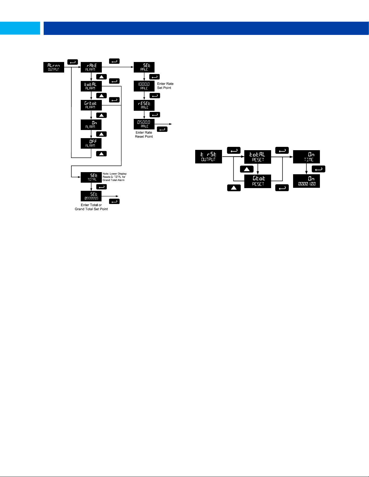
PD6730 Vantageview Pulse Input Rate/Totalizer Instruction Manual
Alarm Output (alrm)
Alarm outputs may be assigned to rate, total, or grand total;
or be forced on or off.
Timer Output (tmer)
The timer output produces a constant width pulse at a
constant rate. Program the Delay Period for one period from
0.1 to 999999.9 seconds (time from the start of one pulse to
the start of the next pulse).
Program the On Time for the active low pulse from .01 to
99999.99 seconds (pulse width). The on time must be less
than the delay time.
Select Start to begin outputting the constant timed pulse.
Select Stop to end outputting the constant timed pulse.
Total Reset Output (t rst)
A total reset output generates a pulse whenever the selected
total is reset, total or grand total, regardless of the reset
method used. Program the On Time from 0.10 to 99,999.99
seconds. This is the amount of time the open collector output
will remain on after the total or grand total has been reset.
Rate Alarm (rate)
Program the rate set point to trigger the alarm. Rate alarm
deadband is determined by the difference between set and
reset points. Minimum deadband is one display count. If set
and reset points are programmed the same, output will reset
one count below set point.
Total or Grand Total Alarm (Total, Grtot)
Program total or grand total set point. A pulse alarm will
generate when the set value is reached by the total or grand
total.
If the total/grand total is set for manual reset, this alarm will
remain until the total/grand total is reset to 0.
If automatic total/grand total reset is enabled, the output will
generate an alarm for a period of time programmed in
ADVANCE T RESET Auto T DELAY. After this time
delay, the total/grand total will reset to 0 and the alarm will
clear.
If Out 1 and Out 2 are set for total or grand total alarm, the
auto reset will be triggered on the highest of the two alarm
set points.
For details on setting the total or grand total automatic reset
time delay, see Total Reset (T Reset) on page 30.
Force On State (On)
This alarm mode forces the output to be active, or on. This
mode is primarily used to test alarm systems.
Force Off State (OFF)
This alarm mode forces the output to be inactive, or off. This
mode is primarily used to test alarm systems.
26
Find Quality Products Online at: [email protected]
www.GlobalTestSupply.com
Page 27
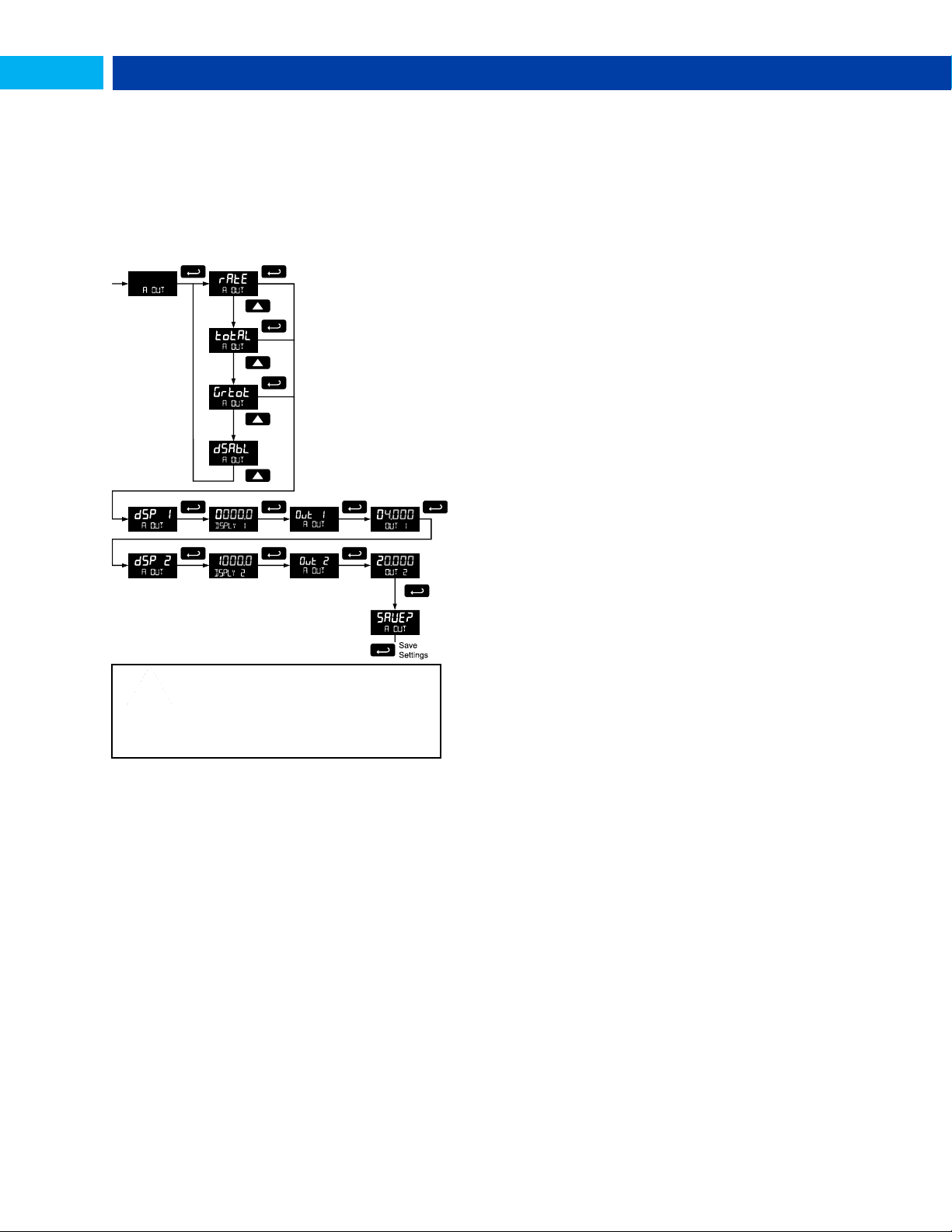
PD6730 Vantageview Pulse Input Rate/Totalizer Instruction Manual
CAUTION
Please note that when power is removed
from the meter, the analog output will drop
below 1 mA.
Take this effect into consideration when
designing any system using the 4-20 mA
output.
Scaling the 4-20 mA Analog Output (Aout)
The Analog Output menu is used to program the 4-20 mA
output based on display values.
The 4-20 mA analog output (if equipped) can be scaled to
provide a 4-20 mA signal for any display range selected for
either the rate, total, or grand total. The output may be
disabled (DSABL), and will only output the minimum signal.
No equipment is needed to scale the analog output; simply
program two display values and corresponding mA output
signals.
High Gate (HI GaTE)
Set the high gate value to correspond to the highest
expected pulse period (lowest pulse rate). For instance if the
meter must display a rate when there is 1 pulse coming into
the meter every 10 seconds, set the high gate to 11
seconds. When the signal is removed from the meter, the
display will show the last reading for 11 seconds; then it will
read zero.
Contact Debounce Filter (FILTER)
The filter function (FILTER) can be used for applications
where the meter is set up to count pulses generated by
switch contacts. There are three settings, HI (high speed),
nmed (medium speed), and LO (low speed). High speed
disables the contact debounce filter and allows any pulse of
the minimum specified width for the selected input type.
Press ENTER when nmeD or LO is displayed to enable the
filter function.
The medium filter ignored signals faster than 250 Hz max, or
pulse widths less than 2 ms at 50% duty cycle. The low filter
ignores signals higher than 100 Hz, or pulse widths less than
5 ms at 50% duty cycle.
Low-Flow Cutoff (CUTOFF)
The low-flow cutoff feature allows the meter to be
programmed so that the often-unsteady output from a
transmitter at low flow rates, always displays zero on the
meter.
The cutoff value may be programmed from 0 to 9999.9.
Below the cutoff value, the meter will display zero.
Programming the cutoff value to zero disables the cutoff
feature.
Gate Function (GATE)
The gate function is used for displaying slow pulse rates.
Using the programmable gate, the meter is able to display
pulse rates as slow as 1 pulse every 9,999 seconds (0.0001
Hz). The gate function can also be used to obtain a steady
display reading with a fluctuating input signal.
There are two settings for the Gate, low gate (LO) and high
gate (HI).
Low Gate (LO GaTe)
For most applications, low gate setting should be left at 1
second. Increase low gate setting to obtain a steadier rate
display. The rate display will update in accordance with the
low gate setting, for example if low gate is set at 10, the
display will update every 10 seconds; changes in rate
between updates will not be reflected until next display
update.
27
Find Quality Products Online at: [email protected]
www.GlobalTestSupply.com
Page 28
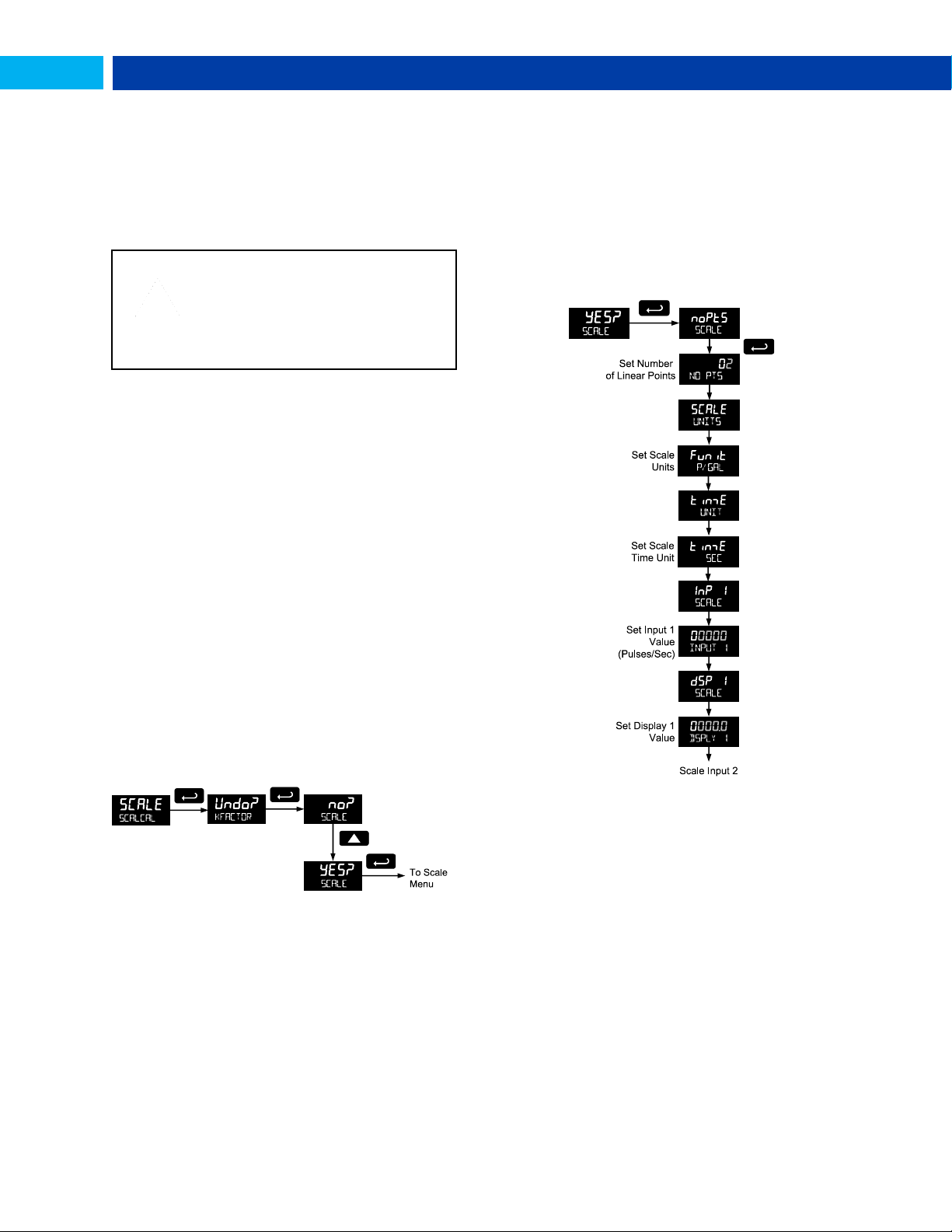
PD6730 Vantageview Pulse Input Rate/Totalizer Instruction Manual
IMPORTANT
Performing a scaling or calibration
operation will override any k-factor
programming. Similarly, completing the k-
factor menu will override any scaling or
calibration performed on the meter. Verify
the method of programming required, use
the password protection feature to secure
the meter if necessary.
Scaling & Calibration (SCALCAL)
It is very important to read the following information, before
proceeding to program the meter:
There is no need to recalibrate the meter for
frequency in Hz when first received from the factory.
The meter is factory calibrated for Hz prior to
shipment. The calibration equipment is certified to NIST
standards.
There are three methods of programming the display to
show the correct engineering units based on input pulses.
Use the Factor menu to enter a K-Factor.
Use the Scale menu to enter the scaling without a signal
source.
Use the Calibrate menu to apply a signal from a
calibrator or a flowmeter.
The k-factor, scale, and calibrate functions are exclusive of
each other. The meter uses the last function programmed.
The Scale and Calibrate functions can use up to 32 points
(default is 2). The number of points should be set in Scale
and Calibrate accordingly under the Number of Points
(nopts) menu selection prior to scaling and calibration of the
meter, see page 28 for details.
This menu is used to scale and calibrate the meter. For
information on using a k-factor for programming the input,
refer to Entering the K-Factor (Factr) on page 17.
Undoing K-Factor, Scale, and Calibration
(Undo?)
Whenever the input programming is being changed from
using k-factor to scaling or calibration; or from scaling or
calibration to k-factor, a confirmation menu appears. This
prevents accidental changing of the input programming.
The example below shows a meter programmed with a kfactor being reprogrammed to utilize input scaling.
Scaling the Meter (SCale)
The pulse input can be scaled to display the process
variable in engineering units.
A signal source is not needed to scale the meter; simply
program the inputs and corresponding display values.
A programmed scaled input will work with Automatic Unit
Conversions as described on page 20. The units for the
display values that must be entered are a combination of the
programmed Rate Unit and the time unit (Time UNIT)
entered in the Scale menu.
For example, if the Rate Unit is gallons, and the time unit
(Time UNIT) is seconds, the units for the display values
entered in the Scale menu are gallons/second.
For instructions on how to program numeric values see page
13.
Multi-Point Linearization (nopts)
Up to 32 linearization points can be selected under the
nopts function. The multi-point linearization can be used to
linearize the display for non-linear inputs.
Number of Points (nopts)
Enter number of linearization points. The default value is 2
points. For linear inputs requiring only 2 scale points, the
number of points can be left at 2.
Scale Units (SCALE UNITS)
Enter the units associated with the desired scale values.
Selecting the scale display units allows the meter to perform
automatic unit conversions.
Find Quality Products Online at: [email protected]
28
www.GlobalTestSupply.com
Page 29
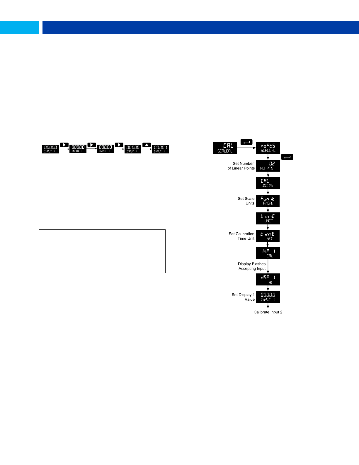
PD6730 Vantageview Pulse Input Rate/Totalizer Instruction Manual
Important Programming Note: Save (save?)
After entering the last display value, the scaling entries
must be saved (SAUE?) before they will be put into effect.
However, you may move past this selection using the Up
arrow key if you need to go back and correct an earlier
entry. Once confident in the entries, however, the user
must navigate back to the Save menu screen (SAUE?)
and press the Enter key to save the changes.
Pulse Input Time Unit (Time UNIT)
This is the time component for the engineering units of the
display values being entered. Enter the appropriate
units/second, units/minute, units/hour, or units/day that
corresponds to the values being entered at the display 1-32 (
dsp) menus.
For example, if the display values are being entered in
gallons/second the time unit would be set to seconds.
Scale Input and Display (INPUT,
DSPLY)
Each scale input point is defined by an input frequency and a
corresponding display value.
The frequency inputs may be entered with up to three
decimal places. To access the decimal location digits when
entering a frequency, use the Right button to scroll to the
three decimal location digits.
Manual Multi-point Entry (INP, DSP)
Manual entry of the linearization data is done once the
number of points has been selected (NO PTS). Input signal
levels (InP 1-32) for up to 32 points, along with the
desired/corresponding meter reading (dSP 1-32), should be
entered for each linearization point.
Each scale point (1-32) has an input value and a display
value. The input value is the number of pulses/sec
(frequency), and the display value is the corresponding
display value for that input in the time unit selected
(example: gallons per minute, or GAL/M)
Calibrating the Meter (CaL)
To scale the meter without a signal source refer to Entering
the K-Factor (Factr) on page 17 or Scaling the Meter
(SCale) on page 28.
The pulse input can be calibrated to display the process in
engineering units by applying the appropriate input signal
and following the calibration procedure.
The use of a calibrated signal source is strongly
recommended.
A calibrated input will work with Automatic Unit Conversions
as described on page 20. The units for the display values
that must be entered are a combination of the programmed
Rate Unit and the time unit (Time UNIT) entered in the
Calibrate menu.
For example, if the Rate Unit is gallons, and the time unit
(Time UNIT) is seconds, the units for the display values
entered in the Calibrate menu are gallons/second.
The multi-point linearization feature (nopts) can be used to
linearize the display for non-linear signals. For instructions
on how to utilize this feature, see Multi-Point Linearization
(nopts), page 30.
Find Quality Products Online at: [email protected]
www.GlobalTestSupply.com
29
Page 30
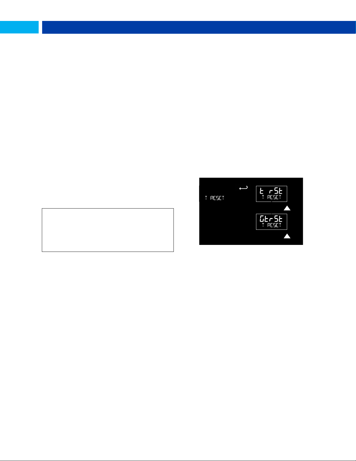
PD6730 Vantageview Pulse Input Rate/Totalizer Instruction Manual
Important Programming Note: Save (save?)
After entering the last display value, the calibration entries
must be saved (SAUE?) before they will be put into effect.
However, you may move past this selection using the Up
arrow key if you need to go back and correct and earlier
entry. Once confident in the entries however, the user must
navigate back to the Save menu screen (SAUE?) and press
the Enter key to save the changes.
For instructions on how to program numeric values see
Setting Numeric Values, page 13.
1. Press the Up arrow button to scroll to the Calibration
menu (CAL) and press Enter.
2. The meter displays nopts. For a linear signal, press
Up arrow. For a non-linear signal, refer to Multi-Point
Linearization (nopts), page 30.
3. The meter displays CAL UNITS. Press Enter to select
the input units/pulse. The menu will read FuNiT.
4. Use the Up arrow to select the time unit. If entering
display values in units/second, press Enter.
Otherwise, select the time unit. Refer to Pulse Input
Time Unit (Time UNIT) on page 30.
5. The meter displays inp 1. Apply a known signal and
press Enter. The display will flash while accepting
the signal.
6. After the signal is accepted, the meter displays dsp
1 Press Enter. Enter a corresponding display value
for the signal input, and press Enter to accept.
7. The meter displays inp 2. Apply a known signal and
press Enter. The display will flash while accepting
the signal.
8. After the signal is accepted, the meter displays dsp
2. Press Enter. Enter a corresponding display value
for the signal input and press Enter to accept.
9. After completing calibration the save? display will
need to be acknowledged using the Enter key before
calibration will take effect.
Multi-Point Linearization (nopts)
Up to 32 linearization points can be selected under the
nopts function. The multi-point linearization can be used to
linearize the display for non-linear inputs. Linearization data
can be entered using a known accurate signal source (InP
1-32) and then entering the desired/corresponding meter
reading (dSP 1-32) for that input signal level. These points
are established via direct entry (SCALE) or with an external
calibration signal (CAL).
Calibration Units (CAL UNITS)
Enter the units associated with the desired scale values.
Selecting this unit allows the meter to perform automatic unit
conversions.
Pulse Input Time Unit (Time UNIT)
This is the time component to be used when calibrating a
number of input pulses per time unit to equal a certain
display value.
For example, if the inputs being entered in pulses/second
the time unit would be set to seconds.
Total Reset (T Reset)
This menu is used to select the ways the total and grand
total may be reset.
Error Message (Error)
An error message indicates that the calibration or scaling
process was not successful. After the error message is
displayed, the meter reverts to input 2 during calibration or
scaling, allowing the appropriate input signal to be applied or
programmed.
The error message might be caused by any of the following
conditions:
1. Input signal is not connected to the proper terminals or it
is connected backwards.
2. Minimum input span requirements not maintained.
3. Input 1 signal inadvertently applied to calibrate
input 2.
Minimum Input Span
The minimum allowed input span is 1 Hz, which is the minimum difference between input 1 and input 2 signals required
to complete the calibration or scaling of the meter.
Manual or Automatic Total Reset
Function (t rST)
For manual reset, select T RESET t rst man and
then select whether manual reset will be enabled (Enabl) or
disabled (dsabl) using the Up arrow key. Press the Enter
button to accept. Disabling reset will avoid inadvertent resets
of the total via the front reset button or external reset
contact.
For automatic reset, select T RESET t rst Auto T
DELAY and enter reset delay time in seconds. Once the
output alarm total set point is reached, the meter waits for a
programmed amount of time (T DELAY) and then resets the
total to zero.
For timed reset, select T RESET t rst Time T
RESET and enter the time of day at which the total should be
reset. The total value will be reset every day at the specified
time.
Press the Enter button, at any time, to accept a setting;
otherwise press the Menu button to exit without saving
changes.
Find Quality Products Online at: [email protected]
www.GlobalTestSupply.com
30
Page 31
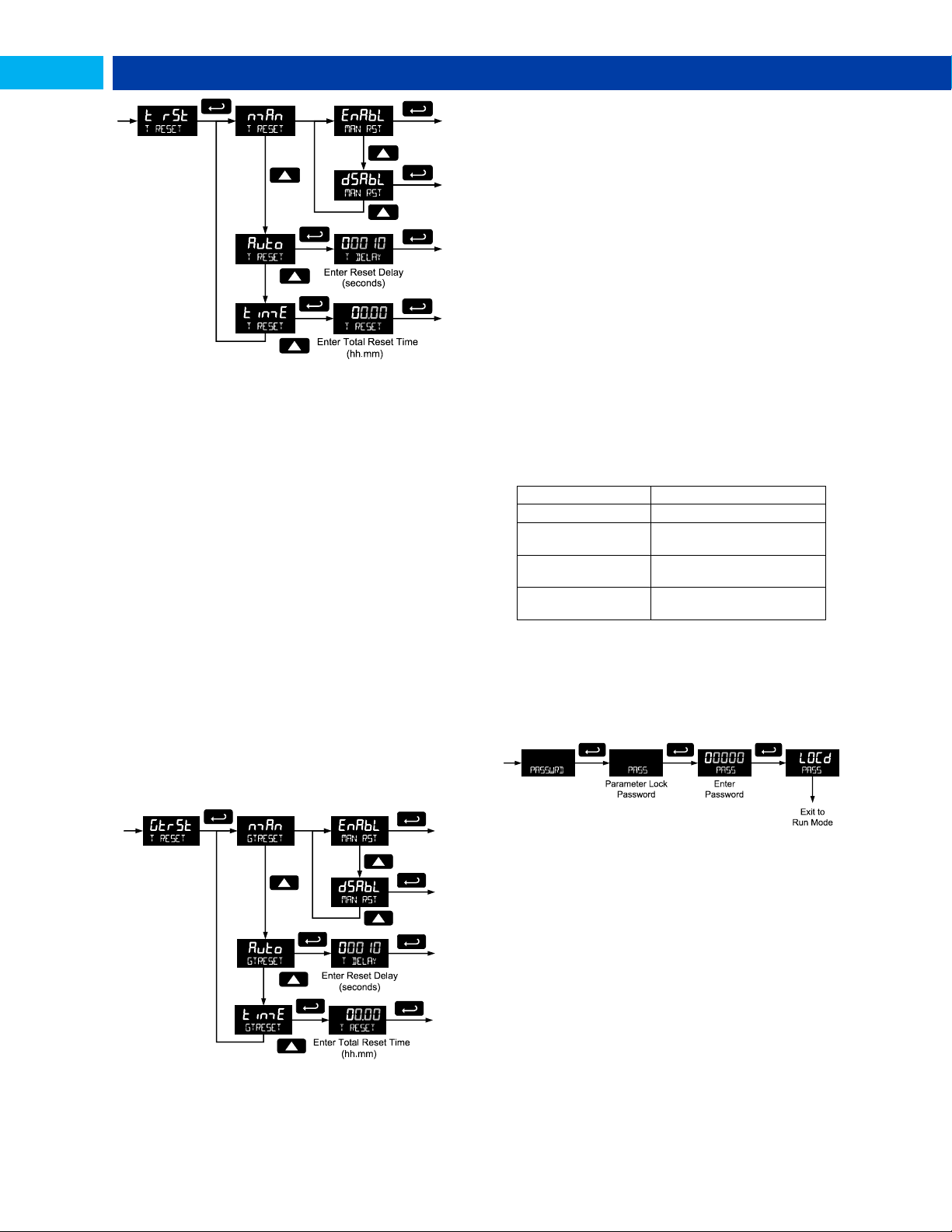
PD6730 Vantageview Pulse Input Rate/Totalizer Instruction Manual
Model:
Serial Number:
Setting Lockout
Password (PASS):
__ __ __ __ __
Total Reset
Password (PASS T):
__ __ __ __ __
Grand Total Reset
Password (PASS GT)
__ __ __ __ __
Total Alarm Time
The T DELAY parameter is used by the NPN open collector
outputs when they are programmed as total alarms. If total
reset (t rst) is programmed to Auto the time delay (T
DELAY) is the length of the associated Out 1 or Out 2 total
alarm prior to the total being reset to 0.
For information on programming the NPN open collector
pulse outputs as total alarms, see Alarm Output
programming on page 26.
Manual or Automatic Grand Total Reset
Function (GtrST)
For manual reset, select T RESET Gtrst man and
then select whether manual reset will be enabled (Enabl) or
disabled (dsabl) using the Up arrow key. Press the Enter
button to accept. Disabling reset will avoid inadvertent resets
of the total via the front reset button.
For automatic reset, select T RESET Gtrst Auto T
DELAY and enter reset delay time in seconds. Once the
grand alarm output grand total set point is reached, the
meter waits for a programmed amount of time (T DELAY) and
then resets the grand total to zero.
For timed reset, select T RESET t rst Time T
RESET and enter the time of day at which the total should be
reset. The total value will be reset every day at the specified
time.
Press the Enter button, at any time, to accept a setting;
otherwise press the Menu button to exit without saving
changes.
Grand Total Alarm Time
The T DELAY parameter is used by the NPN open collector
outputs when they are programmed as grand total alarms. If
grand total reset (Gtrst) is programmed to Auto,the time
delay (T DELAY) is the length of the associated Out 1 or Out
2 grand total alarm prior to the grand total being reset to 0.
For information on programming the NPN open collector
pulse outputs as grand total alarms, see Alarm Output
programming on page 26.
Press the Enter button, at any time, to accept a setting;
otherwise press the Menu button to exit without saving
changes.
Setting Up Passwords (PASSWRD)
The Password menu is used to program a five-digit
password to prevent unauthorized changes to the
programmed parameter settings, to restrict the ability to
reset the total and grand total, and to permanently lockout
the ability to reset the grand total and any grand total related
parameters.
The lock symbol is displayed to indicate that settings are
password protected.
Record all passwords for future reference. If appropriate, it
may be
recorded in the space provided.
Locking Meter Setup Parameters
Enter the Password menu, select Pass, and program a fivedigit password. The meter will return to Run Mode after
locking any of the passwords.
For instructions programming numeric values see Setting
Numeric Values, page 13.
Making Changes to a Password Protected
Meter
If the meter is password protected, the meter will display the
message PASS LOCKED when an attempt is made to enter
the Setup menu or Advanced menu. Press the Enter button
while the message is being displayed and input the correct
password followed by the Enter button to gain access to the
menu. After exiting the programming mode, the meter
returns to its password protected condition.
Find Quality Products Online at: [email protected]
www.GlobalTestSupply.com
31
Page 32
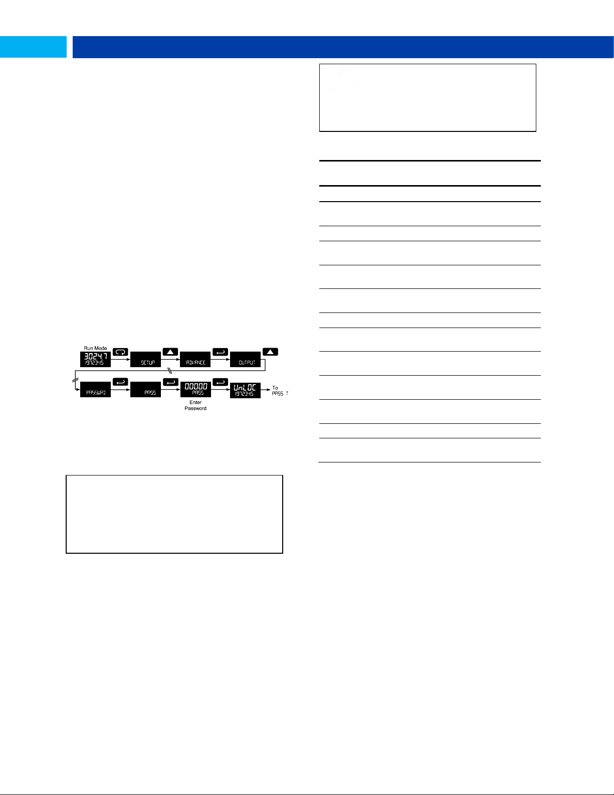
PD6730 Vantageview Pulse Input Rate/Totalizer Instruction Manual
Did you forget the passwords?
The password may be disabled by entering a master
password. If you are authorized to make changes, enter
the master settings lockout (PASS) password 50865, the
master total reset (PASS T) password 80034, or the
master grand total reset (PASS GT) password 80034 to
unlock the meter.
CAUTION
Locking the meter into a non-resettable
grand total is not reversible. It is a
permanent meter configuration. Doing so
will permanently prevent most input
parameters from being altered. This should
be the last step after verifying all setup
parameters.
Non-Resettable Grand Total
Locked Menus & Parameters
Display
Parameter/Menu
Action/Setting Locked
Input
Input
All Input type selection
menu parameters
GtotU
Grand total units
Set grand total units
GrtCF
Grand total
conversion factor
Enter the Grand Total
Conversion Factor menu
Grtot
DECIMAL
Grand total
decimal point
Enter the grand total
display decimal point
Factr
K-factor
All K-Factor menu
parameters
sCalE
Scale
All Scale menu parameters
Cal
Calibrate
All Calibrate menu
parameters
GTrST
Grand total reset
All the Grand Total Reset
menu parameters
Pass GT
Password grand
total
Enter the grand total reset
password
Grtot
ALARM
Grand total alarm
All grand total alarm output
menu parameters
FILTER
Filter
Enter Filter parameter
CUTOFF
Low-flow cutoff
Enter Low-Flow Cutoff
parameter
Password Restricting Total & Grand Total
Reset
To restrict resetting of the total, enter the Password menu,
select Pass T, and program a five-digit password. This will
deactivate the remote reset connections. Total will only be
able to be reset through the SafeTouch Buttons or
mechanical pushbuttons, if the appropriate password is
entered.
To restrict resetting of the grand total, enter the Password
menu, select Pass GT, and program a five-digit password.
Resetting Total & Grand Total on a
Password Protected Meter
If the meter is password protected for total or grand total
reset, the meter will display the message PASS T or PASS GT
when an attempt is made to enter the password protected
total or grand total Reset menus. Input the password and
press the Enter button to reset the total or grand total.
The password requirement may be disabled by entering the
password in the Password menu for total (Pass T) or grand
total (Pass GT).
Disabling Password Protection
To disable the password protection, access the Password
menu, select the type of password to be disabled, and enter
the correct password as shown below. That password is now
disabled until a new password is entered.
Non-resettable grand total password: 50873
If the correct five-digit password is entered, the meter
displays the message UnlOC (unlocked) and the protection
is disabled until a new password is programmed.
If the password entered is incorrect, the meter displays the
message LOCD,
The above menus remain accessible; however the
parameters listed above within the menus are locked and
may not be changed.
Non-Resettable Grand Total
The grand total may be configured to be a non-resettable
grand total. This is a permanent setting. Configuring the
grand total as a non-resettable grand total locks out all setup
parameters that could be used to reset the grand total or
change the setup of the grand total; including input selection,
rate scaling, and conversion factors.
To configure the meter for non-resettable grand total mode,
enter the non-resettable grand total password below into the
Pass GT parameter in the Password menu.
The non-resettable grand total permanently locks the
following setup menus and parameters from being changed:
input selection, K-factor, K-factor units, grand total units,
grand total conversion factor, grand total decimal point,
scaling, calibration, grand total alarms, pulse input filter, and
cutoff.
Find Quality Products Online at: [email protected]
www.GlobalTestSupply.com
32
Page 33
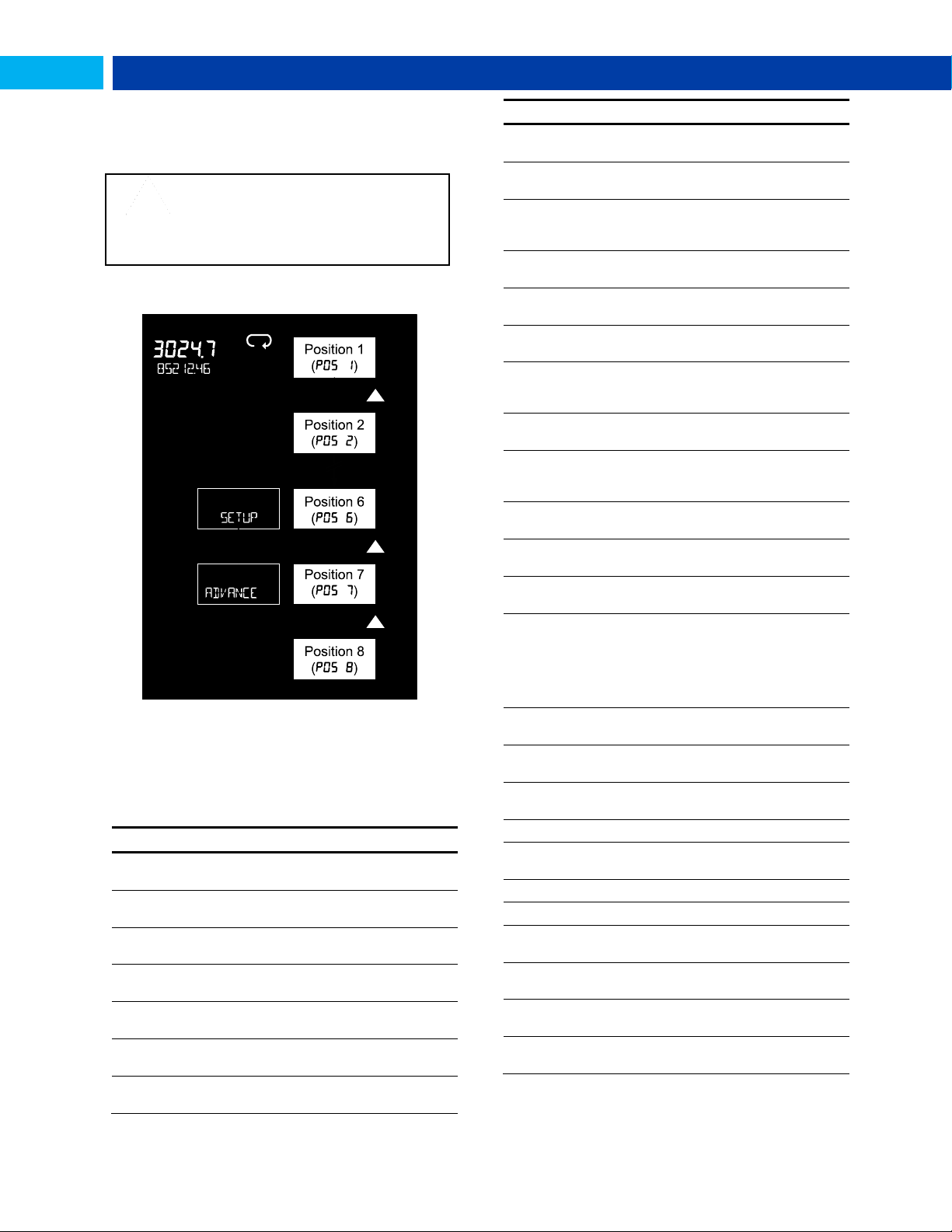
PD6730 Vantageview Pulse Input Rate/Totalizer Instruction Manual
Display
Parameter/Menu
Action
NONE
None
Set no menu position
display
INPUT
Input
Set to show Input
menu
KFACTOR
K-Factor
Set to show K-Factor
menu
UNITs
Units
Select standard units
or custom unit/tag
DECIMAL
Decimal
Set to show Decimal
menu
DISPLAY
Display
Set to show Display
menu
A OUT
Analog out
Set to show Analog
Output menu
Display
Parameter/Menu
Action
RATE.DP
Rate decimal
Point
Set to show Rate
Decimal Point menu
TOTAL.DP
Total decimal
point
Set to show Total
Decimal Point menu
GRTOT.DP
Grand total
decimal point
Set to show Grand
Total Decimal Point
menu
SCALE
Scale
Set to show Scale
menu
CAL
Calibrate
Set to show Calibrate
menu
T BASE
Time base
Set to show Time Base
menu
T FACTR
Total conversion
factor
Set to show Total
Conversion Factor
menu
T RESET
Total reset
Set to show Total
Reset menu
GTFACTR
Grand total
conversion factor
Set to show Grand
Total Conversion
Factor menu
GTRESET
Grand total reset
Set to show Grand
Total Reset menu
PASS
Password
Program password to
lock meter parameters
PASS T
Total password
Program password to
prevent total reset
PASS GT
Grand total
password
Program password to
prevent grand total
reset. May
permanently lock out
grand total related
parameters and reset
OUTPUT
Output
Set to show Output
menu
OUT 1
Out 1
Assign function of
pulse output 1
OUT 2
Out 2
Assign function of
pulse output 2
DATALOG
Data Log
Enter Data Log menu
LOGTIME
Log Time
Set daily data log
times
INTERVL
Interval
Set interval log times
LOGVIEW
Log View
Enter Log View menu
PASSWRD
Password
Set to show Password
menu
SETUP
Setup
Set to show Setup
menu
ADVANCE
Advance
Set to show Advanced
menu
SYSTEM
System
Set to show System
menu
CAUTION
Changing the default menu setup with the
Custom menu feature may change the
setup and operation procedures described
in this manual. Only operators familiar with
the programming and operation of this unit
should use this feature.
Custom (CUSTOM)
The Custom menu is used to modify the initial programming
menus that appear in the Main Menu when the Menu button
is pressed in Run Mode.
Eight menu positions are available. Menu positions 6 and 7
are factory programmed for Setup and Advanced.
To add a menu or parameter to the menu structure, or
change the default menus, press Enter at the desired menu
in the position (POS) to be edited, and use the Up or Right
arrows to select the desired menu item for that position. See
page 33 for a complete list of the available menu selections
for each position.
Custom Menu Parameters
Find Quality Products Online at: [email protected]
33
www.GlobalTestSupply.com
Page 34
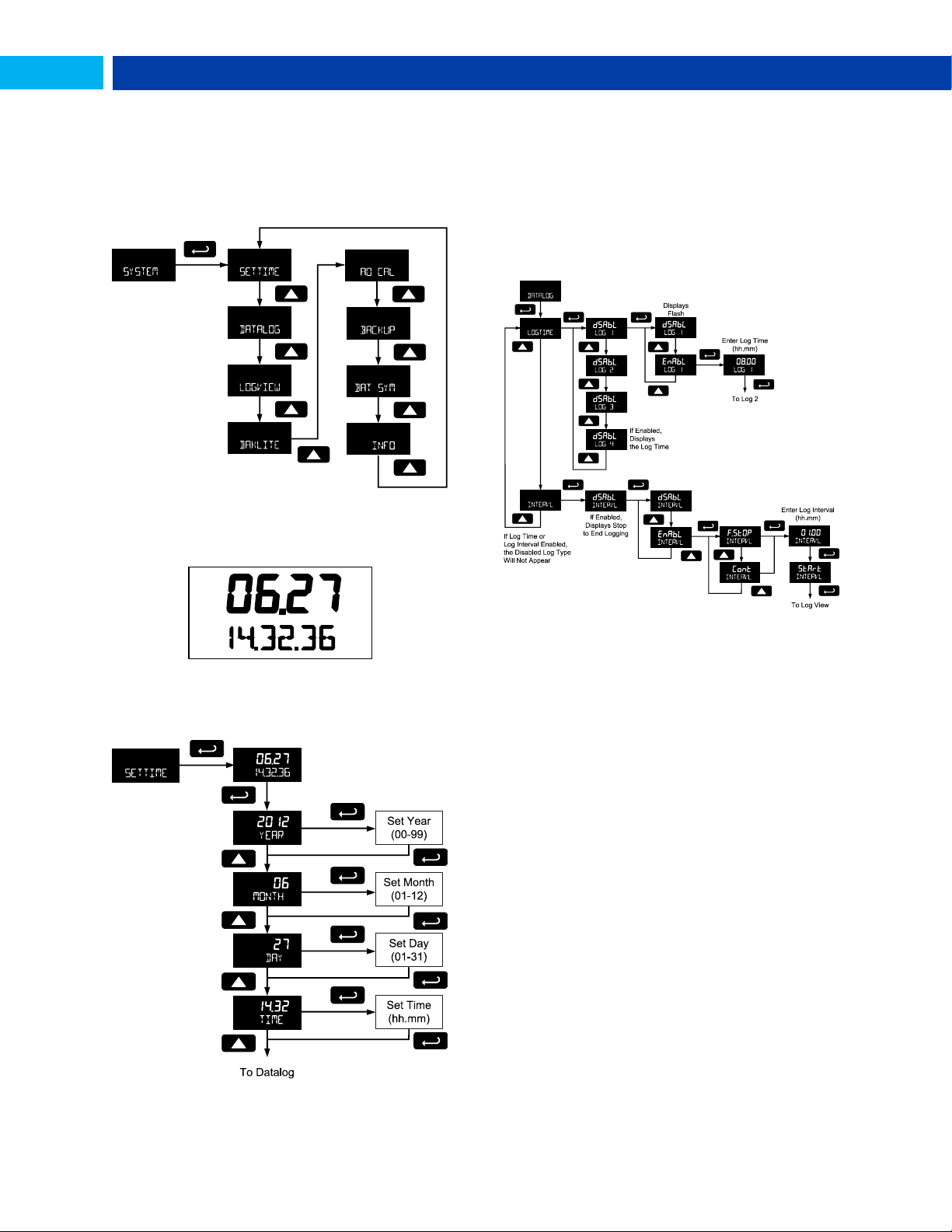
PD6730 Vantageview Pulse Input Rate/Totalizer Instruction Manual
System (SYSTEM)
The system function is used to set the real time clock, set
daily data log times, enable/disable the backlight, access
analog output controls used in troubleshooting, store,
restore, and backup restore feature, enable/disable the
battery power alert symbol on the display, and review basic
system identification information.
Set Real Time Clock (SETTIME)
The real time clock is used to trigger data log events, and is
recorded at every logged data point. The menu displays the
date and time.
The year, month, day, hour, and minute may all be set by the
user. The real time clock will need to be reset if external
power and battery power are lost.
Changing the time (hours and minutes) will reset the
seconds clock to 0.
Data Log Setup (DATALOG)
The Data Log menu is used to setup and enable the data log
functions. The meter may contain up to 1024 records, each
containing date, time, rate, total, grand total, and log
number.
Figure 15. Date Display Example
The above display example shows the date to be June 27, at
14 hours, 32 minutes, and 36 seconds. The display date will
toggle with the year.
There are two ways to configure the time when a data log is
recorded. The Log Time feature allows up to 4 data logs to
be recorded each day, at specific times. The Log Interval
feature allows a data log to be recorded each time a time
interval has passed.
Only the Log Time or Log Interval may be active at once.
While one type of data logging has been enabled, the other
menu will be inaccessible.
Log Time Setup (LOGTIME)
The Log Time menu contains four log points (LOG 1 to LOG
4). Each log time is configured separately. For each daily log
time desired, enable a log, and set the log time for the hours
and minutes the log is to be recorded. The time is set in realtime, based on the real time clock setup.
The Log Time feature will roll-over, deleting the oldest data
logs (in blocks of 8) when the log is full and new logs must
be recorded. This makes it the most useful for long-term
data logging.
34
Find Quality Products Online at: [email protected]
www.GlobalTestSupply.com
Page 35
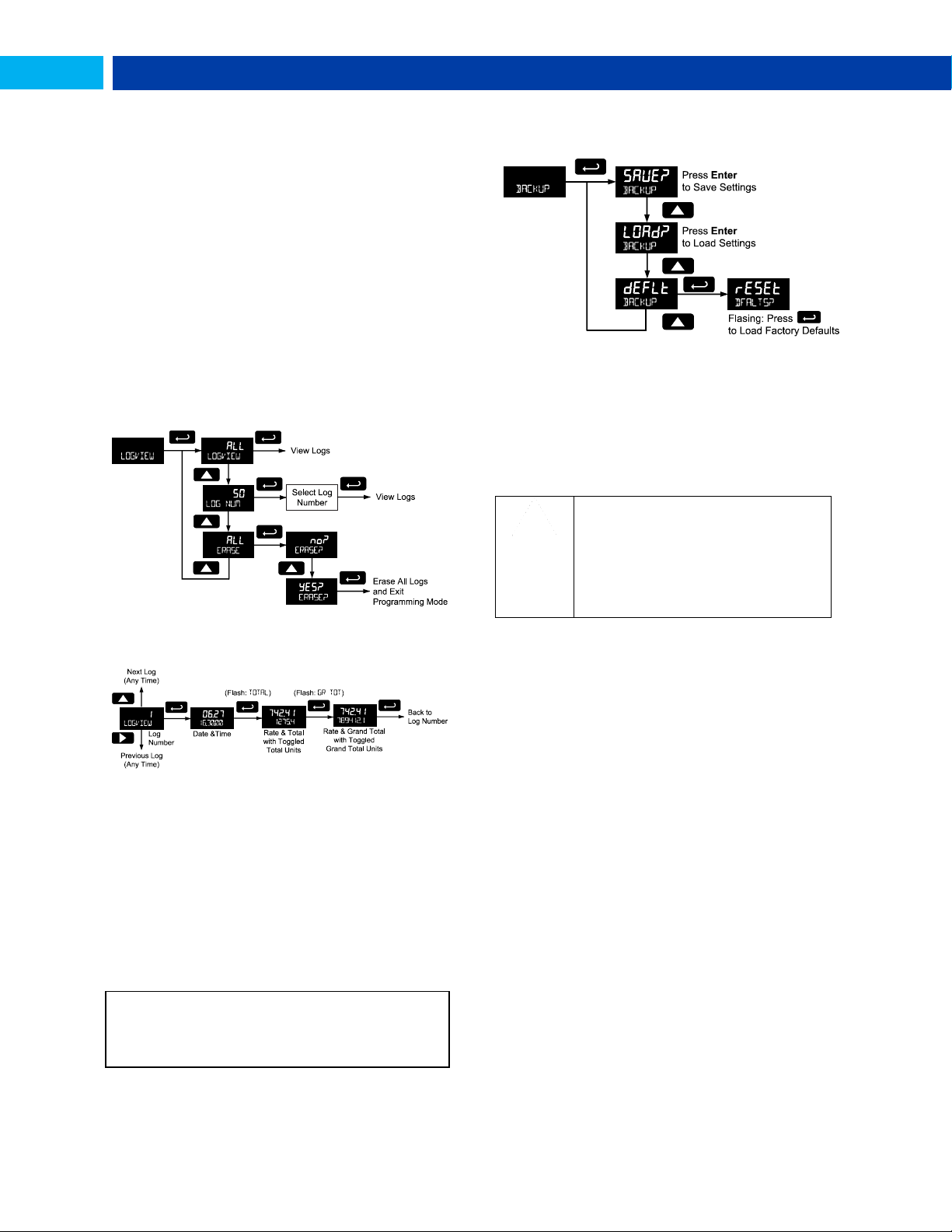
PD6730 Vantageview Pulse Input Rate/Totalizer Instruction Manual
CAUTION
Once meter parameters have been saved
to memory by the backup restore feature
there is no recovering the previously saved
settings.
Once parameters have been loaded into
the meter from the backup restore feature
there is no recovering the previously
programmed settings.
The meter saves all parameter settings and no
reprogramming is necessary when power is lost and
restored to the meter. The total and grand totals are saved
during a power loss. Only the maximum and minimum
displays are reset when power is lost.
Interval Setup (INTERVL)
The Interval menu sets the time interval for data logging.
Every time interval, one data point will be recorded. To
enable interval data logging, enable the feature, and set the
interval time for the hours and minutes between each log.
If set to F.STOP, the Log Interval feature will not delete old
data, and data logging will stop when the log is full. This
makes it the most useful for short periods and logging
specific functions.
If set to Cont, the Log Interval feature will delete the old data
when full and continue logging data. The Log Interval feature
will roll-over, deleting the oldest data logs (in blocks of 8)
when the log is full and new logs must be recorded. This
makes it the most useful for long-term data logging.
View Data Log (LOGVIEW)
The Log View menu allows on-screen browsing of the data
log points stored in the meter. Data points may be navigated
by viewing the log number, date and time, total, or grand
total amounts. A known log may be jumped to immediately,
avoiding a lengthy search for data. All logs may be deleted
with the ERASE command, requiring confirmation.
good configuration, or to factory defaults. This is useful to
restore meters whose programming has been altered in
unknown ways, or to quickly restore known good settings if
mistakes are made during reprogramming.
The save feature (SAvE?) saves all current parameter
settings into the memory of the backup restore. The backup
restore feature is loaded with factory default settings until a
new configuration is saved.
The load feature (load?) restores all parameters to the
programmed values stored in backup restore memory. The
load feature will not affect the current password settings, or
allow the editing of permanently locked parameters due to
the enabling of the non-resettable grand total feature. See
Non-Resettable Grand Total described on page 32.
Once the log records are displayed, use the Up and Right
arrows to change the log entry being viewed. The Enter key
changes the displayed information for the same log.
Backlight (BAKLITE)
The Backlight menu is used to enable or disable the
backlight. This feature is particularly important for the
battery-powered models with momentary backlight. This
feature is not available for models with a loop output
powered backlight.
Analog Output Calibration (AO CAL)
This feature is only used at the factory for diagnostic
purposes. It is not recommended to access this menu
without instruction from technical support.
Backup & Restore (BACKUP)
The default feature (deflt) restores all parameters to the
factory default values. Factory default reset does not change
the saved backup restore settings, override passwords, or
edit parameters locked by a permanent non-resettable grand
total. See Non-Resettable Grand Total, as described on
page 32.
Battery Power Symbol Alert (BAT SYM)
The Battery Power Symbol Alert menu is used to enable or
disable the battery alert symbol on the display. This is a
useful way to be aware of a power failure to a model with
battery backup.
When enabled, the battery symbol will appear whenever the
meter is powered as a battery backup. This is detected when
the meter being powered from DC or loop-power
experiences power loss, subsequently switching over to
battery power.
The indicator will not appear if the meter is powered on via
battery power, only when there is applied power to the DC or
loop-power lines, followed by power loss. This prevents the
batter indicator from appearing at all times for a primarily
battery powered application.
The battery symbol will flash in a low battery condition
regardless of the setting of this parameter.
The features are used to save and restore programmed
settings. Programming can be restored to a known saved
35
Find Quality Products Online at: [email protected]
www.GlobalTestSupply.com
Page 36

PD6730 Vantageview Pulse Input Rate/Totalizer Instruction Manual
Information (INFO)
The Information menu is part of the System features menu. It
shows software identification number, version number, and
extended model number. To view this information:
Go to the Information menu (INFO) and press Enter button.
Continue pressing Enter to scroll through the displays.
Following the information display, the meter will exit the
Advanced Features menu and return to Run Mode.
Serial Communications (COMM)
The Communications menu is used to setup serial
communications parameters necessary for communication
via Modbus.
Modbus communications is performed with the 2-wire RS485 with Modbus RTU option.
When using more than one meter in a multi-drop mode, each
meter must be provided with its own unique address. The
meter address (Slave ID) may be programmed between 1
and 247. The baud rate may be set to 1,200; 2,400; 4,800;
9,600; 19,200; 38,400; 57,600; or 115,200 bps. The transmit
delay may be set between 0 and
199 ms. The parity can be set to even, odd, or none with 1 or
2 stop bits.
Refer to the PD6830 Modbus Register Tables located at
www.predig.com for details.
Standby Mode (STANDBY)
Standby mode is available on battery powered and battery
backup models only.
The Standby menu is used to enter a power-saving standby
mode that will turn off the display and activate a low power
mode for the through-window buttons. Signal processing
operations will continue to run. This mode may be used to
reduce power consumption and increase battery life when
the meter is not in use.
It may take up to 3 seconds for the meter to enter standby
mode after confirming the flashing display with the Enter
button.
Wakeup the Meter (WAKEUP?)
To bring the meter out of standby mode, press any button
and Wakeup (WAKEUP?) will flash. If using SafeTouch
buttons, it may be required to hold the button for several
seconds.
Confirm that the meter should awaken to run mode by
pressing the Enter key while WAKEUP? is flashing. The meter
will return to the normal run mode.
36
Find Quality Products Online at: [email protected]
www.GlobalTestSupply.com
Page 37
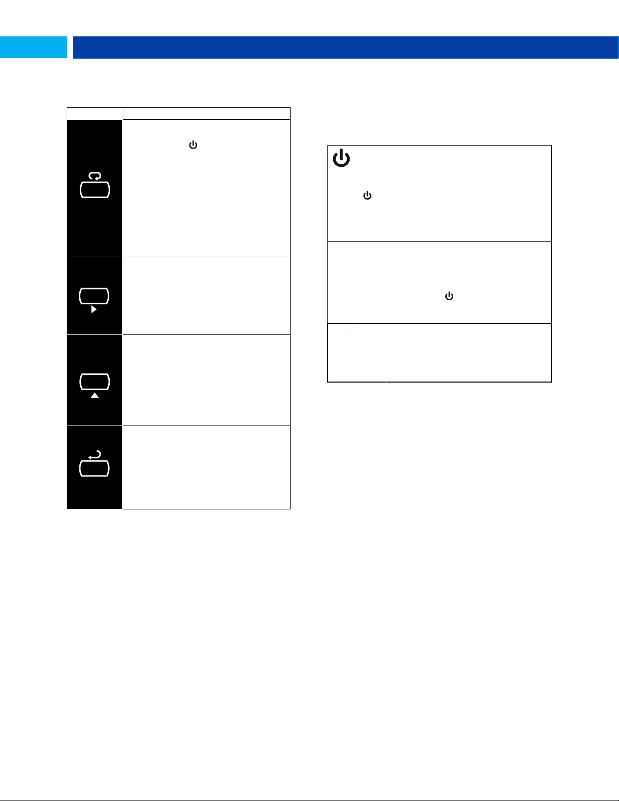
PD6730 Vantageview Pulse Input Rate/Totalizer Instruction Manual
Symbol
Description
Hold the Menu SafeTouch button
when in power save mode (display
will show ) to awaken SafeTouch
buttons.
Press the Menu button to enter
Programming Mode.
Press the Menu button during
Programming Mode to return to
return to the previous menu
selections.
Hold the Menu button for 1.5
seconds at any time to exit
Programming Mode and return to
Press the Right arrow button to
move to the next digit or decimal
position during programming.
Press Right to go backward
through most selection menus.
Press Reset to reset the total, or
values displayed in the bottom
Press Display when in Run mode to
display the grand total, again to
display the maximum, and again to
display the minimum reading since
last reset. These displays will time
out in 12 seconds, or press Display
until total is displayed in the lower
display. Press Enter to lock this
display, and disable the 12 second
Press the Enter button to access a
menu or to accept a setting.
Press Enter to lock the grand total,
maximum, or minimum value on the
lower display, and disable the 12
second time out.
Press Enter while the grand total,
max, or min reading is locked on the
SafeTouch Power Save Mode
SafeTouch buttons enter a power saving mode after three
minutes of inactivity. This mode is indicated by a pause
symbol ( ) appearing in the lower right of the display. Only
the MENU button is monitored in this mode. To activate the
SafeTouch buttons, press and hold the menu button for up
to five seconds. The display will read AWAKE, and the
SafeTouch buttons will be fully enabled.
SafeTouch Disabled Mode
When the cover is removed, the four mechanical buttons
located next to the sensors may be used. The sensors are
disabled when a mechanical button is pressed and will
automatically be re-enabled after 60 seconds of inactivity.
The SafeTouch power symbol ( ) will blink in the lower
right of the display if the buttons are disabled due to a
mechanical pushbutton being pressed.
IMPORTANT
SafeTouch buttons will not work if two or
more buttons are detected as being
pressed simultaneously. As a result, be
careful to avoid triggering multiple buttons
or reaching across one button location to
press another.
M E N U
ENTER
DISPLAY
RESET
OPERATION
Front Panel Buttons Operation
SafeTouch Button Operation
To actuate a button, press and remove one finger to the
window directly over the marked button area. Remove finger
to at least 4 inches away from the window in between button
activations. SafeTouch and mechanical buttons may be held
to cycle through menus or digits in place of repeatedly
pushing a button.
The following SafeTouch button information is reprinted from
SafeTouch Button Operation on page 11.
Find Quality Products Online at: [email protected]
37
www.GlobalTestSupply.com
Page 38
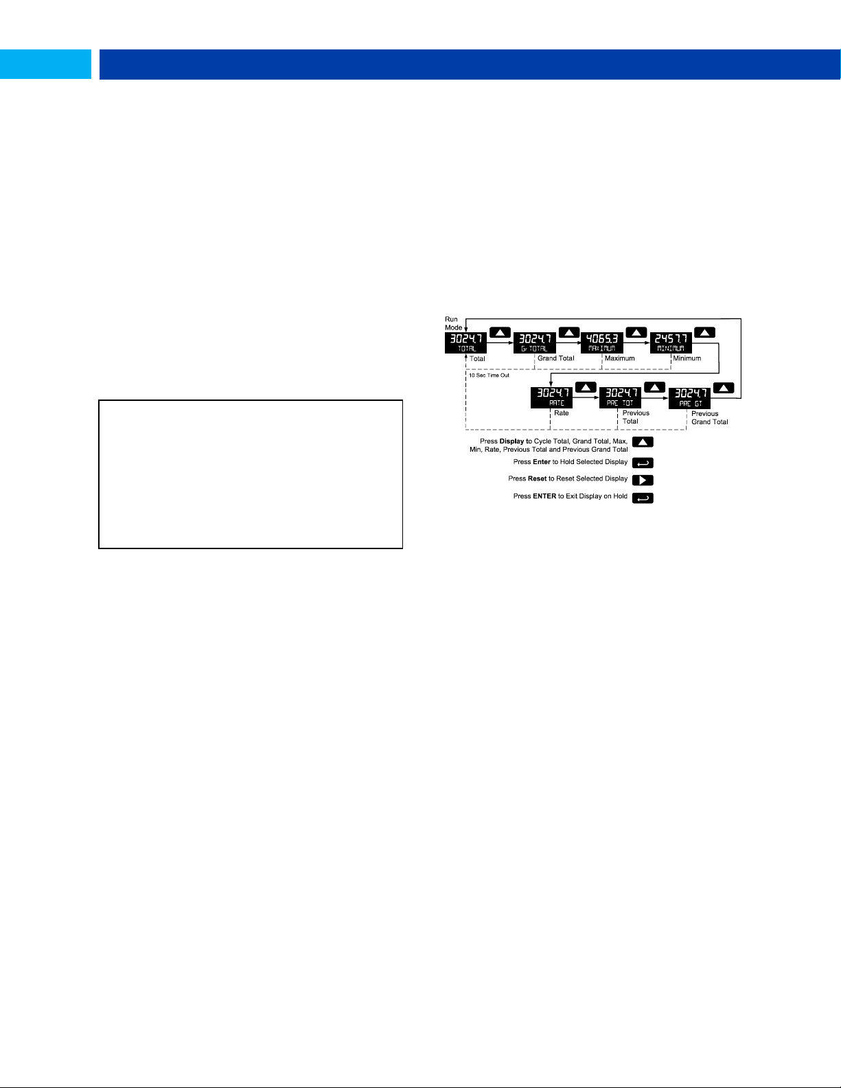
PD6730 Vantageview Pulse Input Rate/Totalizer Instruction Manual
SafeTouch Button Equalize Delay
The SafeTouch buttons are designed to constantly
recalibrate for ambient conditions. When the cover position
is changed, the cover is removed, or an object is removed
that was placed over the front window, it may take a
moment for the SafeTouch buttons to recalibrate to the
change in conditions.
Allow up to 2 minutes for the SafeTouch buttons to
recalibrate to new conditions in these cases where the
cover position was changed, or the front window is being
unblocked.
SafeTouch Button Tips and Troubleshooting
The SafeTouch Buttons are designed to filter normal levels
of ambient interference and to protect against false
triggering, however it is recommended that the SafeTouch
Buttons be turned off (slide THRU-GLASS BUTTONS switch
to OFF) if there is an infrared interference source in line-ofsight to the display or if the buttons are not needed.
SafeTouch Button Tips:
To the extent possible, install the display facing away
from sunlight, windows, reflective objects and any
sources of infrared interference.
Keep the window clean.
Tighten the cover securely.
Use a password to prevent tampering.
If the cover has not been installed and secured tightly, it
may take a moment for the SafeTouch buttons to
properly self-calibrate when the cover is tightened.
After all connections have been completed and verified,
connect the ribbon cable to the display module, fasten the
display module to the base, install enclosure cover, and then
apply power.
Toggle Lower Display Parameter
The maximum and minimum (peak & valley) readings
reached by the rate are stored in the meter since the last
reset or power-up. The meter shows MAXIMUM or MINIMUM to
differentiate between run mode and max/min display. The
previous total and grand total value reached prior to being
reset are also stored.
To display the maximum and minimum readings or the
previous total and grand total use Up/Display button to cycle
the bottom display. Maximum and minimum are displayed
after the grand total.
Press the Enter button to remain in Max/Min/Previous
display mode. If Enter is not pressed, the Max/Min/Previous
display readings will time out after ten seconds. The meter
will return to display the actual reading. Pressing Menu at
any time will return to normal run mode.
Resetting the Total (RESET TOTAL?)
If manual Total Reset is enabled in the Program menu, the
Grand Total Reading (GrTOTAL)
The grand total is a separate total that is not reset when the
total is reset. This allows the complete total to be tracked by
the grand total, while individual batch, or daily totals are
reset regularly.
To display the grand total, press the Up/Display button. The
display will read GRTOTAL, and the GT symbol will appear
indicating the grand total is being displayed on the bottom
display. After 10 seconds, the bottom display will return to
showing total. To lock the grand total on the display, press
Enter. Pressing Menu at any time will return to normal run
mode.
Note: If the Display menu has been setup to display the
grand total on the bottom display, pressing the Up/Display
button will display the maximum and minimum readings
followed by the total.
total may be reset by pressing the Reset button and using
the Enter button to confirm the reset.
Additionally if programmed for manual reset, the total may
be reset using a normally open pushbutton connected
across the terminals RST and COM.
Note: The total is cleared immediately when Enter button is
pressed. Totalization will then continue, even if the Enter
button or external reset button continues to be held
down/triggered.
Resetting the Grand Total (RESET GrTOT?)
If manual Grand Total Reset is enabled in the Program
menu, the grand total may be reset using the Reset button.
To reset the grand total, display the grand total by pressing
the Up/Display button. While grand total is being displayed,
press the Reset button. Confirm the reset with the Enter
button.
Resetting Max/Min Readings (RESET
MAXIMUM, MINIMUM)
The maximum and minimum readings may be reset by
pressing the Reset button while displaying either the
maximum or minimum. The display will show RESET to verify
Find Quality Products Online at: [email protected]
www.GlobalTestSupply.com
the reset of maximum or minimum value.
The maximum and minimum must be reset individually.
38
Page 39

PD6730 Vantageview Pulse Input Rate/Totalizer Instruction Manual
Parameter
Display
Default
Setting
User
Setting
Input Type
INPUT
Active
K-Factor
units
FuNiT
Pulses/
Gallon
K-Factor
Factr
1.0000
Rate Time
Base
Tbase
Second
Rate Unit
RateU
Gallons/
second
Total Unit
Tot U
Gallons
Total
Multiplier
Nmult
x1
Grand
Total Unit
GtotU
Gallons
Grand
Total
Multiplier
Nmult
x1
Rate
Decimal
Point
1111.1
1 place
Total
Decimal
Point
111111.1
1 place
Grand
Total
Decimal
Point
111111.1
1 place
Total
Conversio
n Factor
TotCF
N/A (Only
valid with
custom
units)
Grand
Total
Conversio
n Factor
grtCF
N/A (Only
valid with
custom
units)
Top
Display
TOP
Rate
Parameter
Display
Default
Setting
User
Setting
Bottom
Display
BOTNm
Total
Advanced Features
Total
Reset
T rst
Manual Enabled
Grand
Total
Reset
T rst
Manual Enabled
Analog
Out Value
A out
Rate
Output
Display 1
Dspl1
0000.0
Output 1
Out 1
4.000
Output
Display 2
Dspl2
1000.0
Output 2
Out 2
20.000
Scale
Enable
SCALE
No – Use
K-Factor
Scale/Cal
# Points
nopts
2 (N/A)
Scale Unit
Funit
Pulses/
Gallon
(N/A)
Scale Unit
Time Base
tinme
Second
(N/A)
Scale/Cal
Input 1
Inpt1
00000
(N/A)
Scale/Cal
Display 1
dspl1
0000.0
(N/A)
Scale/Cal
Input 2
Inpt2
1000 (N/A)
Scale/Cal
Display 1
Dspl2
1000.0
(N/A)
Parameter
Lock
Password
PASS
00000
(unlocked)
Total
Reset
Password
PASS T
00000
(unlocked)
Grand
Total
Reset
Password
PASS GT
00000
(unlocked)
Output 1
OUT 1
Off Output 2
OUT 2
Off Low Gate
LO GATE
1 High Gate
HI GATE
2
Filter
FILTER
High
Speed
Cutoff
CUTOFF
0
(disabled)
Battery
Symbol
BaT SYM
Disabled
Reset Meter to Factory Defaults
Reset to factory defaults will restore most meter parameters
to their factory default setting.
When the parameters have been changed in a way that is
difficult to determine what’s happening, it might be better to
start the setup process from the factory defaults.
Factory default reset does not change the saved backup
restore settings, override passwords, or edit parameters
locked by a permanent non-resettable grand total. See NonResettable Grand Total, as described on page 32.
Instructions to load factory defaults can be found in the
Backup & Restore (BACKUP) menu on page 35.
Factory Defaults & User Settings
The following table shows the factory setting for most of the
programmable parameters on the meter. Next to the factory
setting, the user may record the new setting for the particular
application.
Model: _____________________________
S/N: _____________________________
Date: _____________________________
Find Quality Products Online at: [email protected]
www.GlobalTestSupply.com
39
Page 40
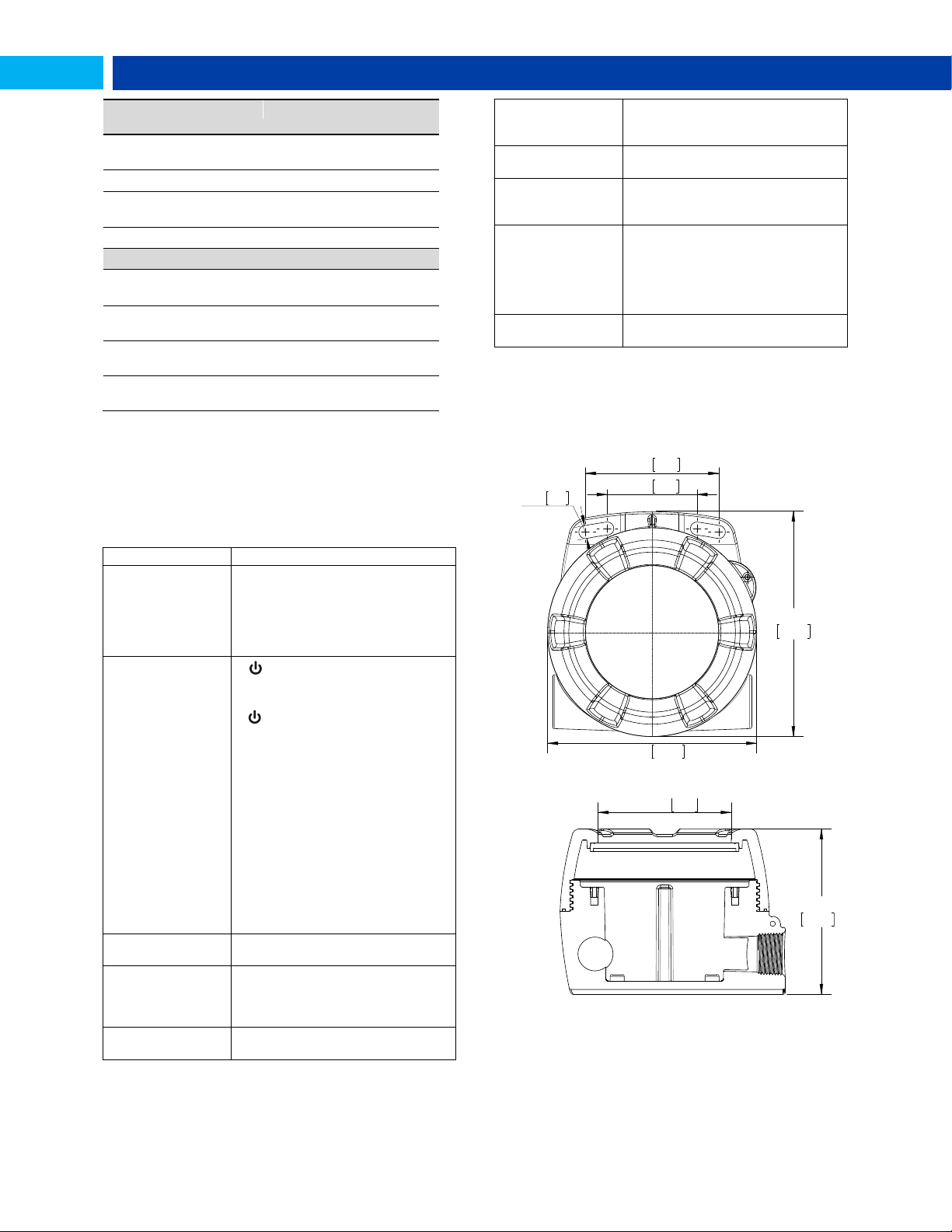
PD6730 Vantageview Pulse Input Rate/Totalizer Instruction Manual
Parameter
Display
Default
Setting
User
Setting
Modbus
Slave ID
sLvID
247
Baud Rate
baud
19,200 bps
Time
Delay
Tdely
10 ms
Parity
Party
Even
Additional Parameters & Notes
Symptom
Check/Action
No display or faint
display
Check power connection.
Press and hold Menu key for 5
seconds to check for Standby mode. If
“WAKEUP?” is displayed, press the
Enter key to awaken the meter from
Standby mode.
SafeTouch Buttons
do not respond
If is displayed, hold Menu
SafeTouch button to leave power
save mode.
If is flashing, wait 60 seconds to
leave mechanical pushbutton lockout
mode.
If the cover was recently tightly
secured, you may need to wait up to 2
minutes for buttons to self-calibrate to
the new cover position due to window
reflection.
Verify THRU-GLASS BUTTONS
switch on display module is in ON
position.
Sunlight can interfere with the sensors.
It is recommended to shield the
window while operating the buttons by
standing so as to block direct sunlight.
Rate display
unsteady
Increase low gate setting in
Advanced menu.
Meter displays error
message during
calibration
(eRRORSpan)
Verify minimum input span
requirements
Meter flashes
99999
Check input signal is within scaled
range of 99999.
Display stuck
displaying MAXIMUM
or MINIMUM
Press Enter (Unlock) to exit Max/Min
display
Display response is
too slow
Check if gate settings can be lowered.
If the display locks
up or the meter
does not respond
Perform hard reset by removing the
display module or by removing
external loop or DC power.
Backlight does not
appear.
Backlight is intended for viewing
assistance in dim lighting. It may not
be noticeable under good lighting
conditions. Battery powered models
turn off the backlight after ten
seconds of button inactivity.
Other symptoms
Call Technical Support for
assistance.
8 5. 1
5 7. 2
1 44 .0
5 .2 5 1 33 .3
5 .6 7
3 .3 5
2 .2 5
0 .3 3
8 .3
1 06 .1
8 5. 1
5 7. 2
1 44 .0
5 .2 5 1 33 .3
5 .6 7
3 .3 5
2 .2 5
0 .3 3
8 .3
4 .1 8
Ø
3 .3 4
8 4. 9
TROUBLESHOOTING
The rugged design and the user-friendly interface of the
meter should make it unusual for the installer or operator to
refer to this section of the manual. If the meter is not working
as expected, refer to the recommendations below.
Note: Certain sequences of events can cause unexpected
results. To solve these issues, it is best to start fresh from
factory defaults and map changes ahead of time, rather than
at random.
MOUNTING DIMENSIONS
All units: inches [mm]
Troubleshooting Tips
Figure 16. Enclosure Dimensions – Front View
Figure 17. Enclosure Dimensions – Side View
Note: The supplied conduit plug may extend up to 0.21 in
[5.3 mm] from the conduit opening when installed.
Find Quality Products Online at: [email protected]
40
www.GlobalTestSupply.com
Page 41
PD6730 Vantageview Pulse Input Rate/Totalizer Instruction Manual
QUICK USER INTERFACE REFERENCE
Pushbutton
Function
Menu
Go to Programming mode, back out one level of programming.
Hold to enter Advanced Features mode. Leave grand total/max/min mode.
Right Arrow
Move to next digit or decimal point position. Go to reset menu
Return to last programming menu.
Up Arrow
Move to next selection or increment digit.
Enter grand total/max/min display mode.
Enter
Accept selection/value and move to next selection.
Acknowledge Alarm.
Cycle Rate, Total, Grand Total, and Max/Min on Lower Display
While in Run Mode, pressing Display will cycle the rate, total, grand total, and
max/min display. In this mode, the display will show the rate, total, grand total,
maximum, or minimum values since last reset when they are not selected as the
top or bottom display. The grand total, max, or min will display for 10 seconds.
Press Enter while displaying the rate, total, grand total, max, or min, to disable the
10 second time-out and continuously display the rate, total, grand total, max, or
min. Press Enter again to disable this display lock.
Menu for
3 seconds
Operational Modes
Menu
Hold
Menu
Display
Rate, Total,
Grand Total,
Max & Min
Menu Hold
Program
Run
Advanced
Features
Find Quality Products Online at: [email protected]
www.GlobalTestSupply.com
41
Page 42

PD6730 Vantageview Pulse Input Rate/Totalizer Instruction Manual
PRECISION DIGITAL CORPORATION
SFT050 Ver 3.200 & up
Find Quality Products Online at: [email protected]
www.GlobalTestSupply.com
LIM6730_D
01/19
 Loading...