

Page 1
PD663 Explosion-Proof NEMA 4X, IP68
Process Meter
Loop-Powered Meter Instruction Manual
• Explosion-Proof / Flame-Proof Loop-Powered Process Meter
• 4-20 mA Input
• 0.6" (15.2 mm) 3½+ Digits LCD Display; -1999 to 2999
• 1.7 Volt Drop (4.7 Volt Drop with Backlight)
• HART® Protocol Transparent
• Loop-Powered Backlight Option
• Operates from -40 to 75°C (-40 to 167°F)
• Four Internal Buttons for Easy Field Scaling
• Display Mountable at 0°, 90°, 180°, & 270° Degrees
• Flanges for Wall or Pipe Mounting
• Explosion-Proof, IP68, NEMA 4X Die-Cast Aluminum Enclosure
• FM Approved as Explosion-Proof / Dust-Ignition Proof / Flame-Proof
• CSA Certified as Explosion-Proof / Dust-Ignition Proof / Flame-Proof
• ATEX and IECEx Certified as Flame-Proof and Protection by Enclosure
• Conformal Coated PCBs for Dust and Humidity Protection
• Two ½" NPT Threaded Conduit Openings (One Plug Installed)
• Pipe Mounting Kits
• Stainless Steel Tag Available
PRECISION DIGITAL CORPORATION
Find Quality Products Online at: [email protected]
www.GlobalTestSupply.com
Page 2
PD663 Explosion-Proof NEMA 4X, IP68 Loop-Powered Meter Instruction Manual
Disclaimer
CAUTION: Read complete
instructions prior to installation and
operation of the meter.
WARNING: Risk of electric shock
or personal injury
Model
Options Installed
PD663-0L0-00
None
PD663-0K0-00
Loop-Powered Backlight
Model
Description
PDA0003
½" M-NPT to ¾" F-NPT Adapter
PDA1024-01
24 VDC Power Supply for DIN Rail
PDA6631
1.5" U-Bolt Pipe Mounting Kit
PDA6631-SS
1.5" U-Bolt Pipe Mounting Kit,
Stainless Steel
PDA6863
2" Pipe Mounting Kit
PDA6863-SS
2" Pipe Mounting Kit,
Stainless Steel
PDA-SSTAG
Stainless Steel Tag
!
The information contained in this document is
subject to change without notice. Precision
Digital makes no representations or warranties
with respect to the contents hereof; and
specifically disclaims any implied warranties of
merchantability or fitness for a particular
purpose.
Warnings
• This product is not recommended for life
support applications or applications where
malfunctioning could result in personal injury
or property loss. Anyone using this product
for such applications does so at his/her own
risk. Precision Digital Corporation shall not be
held liable for damages resulting from such
improper use.
• Failure to follow installation guidelines could
result in death or serious injury. Make sure
only qualified personnel perform the
installation.
• Never remove the meter cover in explosive
environments when the circuit is live.
• Cover must be fully engaged to meet
flameproof/explosion-proof requirements.
• Cancer and Reproductive Harm
www.P65Warnings.ca.gov. For California
Proposition 65 details please visit our website
www.predig.com
Registered Trademarks
All trademarks mentioned in this document are
the property of their respective owners.
© 2013-2018 Precision Digital Corporation. All
rights reserved.
www.predig.com
Introduction
The PD663 is a loop-powered field meter that is
FM Approved and CSA Certified as ExplosionProof, Dust-Ignition Proof, and Flame-Proof, and
ATEX & IECEx Certified as Flame-Proof and
Protection by Enclosure. The PD663 is easy to
install and program and it can be seen in a
variety of lighting conditions and even in bright
sunlight. The fact that this meter is loop-powered
means that there is no need to run additional,
costly power lines into a hazardous area. The
meter gets all of the power it needs from the
4-20 mA loop and its 1.7 V drop results in a
minimal burden on the loop.
The meter features a wide -40 to 75°C operating
temperature range and comes with two 1/2" NPT
threaded conduit openings and flanges for wall
or pipe mounting. Calibration is a quick process
involving the four internal push buttons. The
PD663’s display will read up to 2999; we call this
3½+ digits!
Ordering Information
Accessories
Limited Warranty
Precision Digital Corporation warrants this
product against defects in material or
workmanship for the specified period under
“Specifications” from the date of shipment from
the factory. Precision Digital’s liability under this
limited warranty shall not exceed the purchase
value, repair, or replacement of the defective
unit.
Find Quality Products Online at: [email protected]
2
www.GlobalTestSupply.com
Page 3

PD663 Explosion-Proof NEMA 4X, IP68 Loop-Powered Instruction Manual
Table of Contents
Introduction ---------------------------------------------------- 2
Ordering Information --------------------------------------- 2
SPECIFICATIONS -------------------------------------------- 4
Input ------------------------------------------------------------------- 4
Product Ratings and Approvals ------------------------------ 5
Electromagnetic Compatibility ------------------------------- 5
Safety Information ------------------------------------------- 5
Installation ------------------------------------------------------ 6
Unpacking ----------------------------------------------------------- 6
Pre-Installed Conduit Plug ------------------------------------- 6
Mounting ------------------------------------------------------------- 6
Cover Jam Screw ------------------------------------------------- 6
Connections -------------------------------------------------------- 7
4-20 mA Input Connections & Wiring Diagrams .......... 7
Setup and Programming ----------------------------------- 8
Buttons and Display --------------------------------------------- 8
Setting Numeric Values ----------------------------------------- 8
Programming the Meter ............................................... 8
Main Menu ----------------------------------------------------------- 9
Main Menu Display Functions & Messages ................. 9
Setting the Decimal Point (dP) ................................... 10
Scaling the Meter (SCL) ............................................. 10
Calibrating the Meter (Cal) ........................................ 10
Re-calibrating the Internal Calibration Reference
(ICal) ........................................................................ 11
Advanced Features Menu ------------------------------------ 11
Advanced Features Menu & Display Messages ........ 11
Signal Input Conditioning Function (Fnc) ................... 12
Information Menu (info) .............................................. 12
Input Signal Filter (FIL) ............................................. 12
Internal Calibration (ICal) ......................................... 12
OPERATION -------------------------------------------------- 13
Front Panel Buttons Operation ----------------------------- 13
Maximum & Minimum Readings (
Reset Meter to Factory Defaults --------------------------- 14
Factory Defaults & User Settings -------------------------- 14
TROUBLESHOOTING ------------------------------------- 15
Troubleshooting Tips ------------------------------------------ 15
MOUNTING DIMENSIONS ------------------------------- 15
QUICK USER INTERFACE REFERENCE ----------- 16
EU Declaration of Conformity -------------------------- 17
HI
&
LO
) -------------- 13
Table of Figures
Figure 1. PD663 Meter Assembly, Rear View ......... 7
Figure 2. PD663 Input Connections without
Backlight ........................................................... 7
Figure 3. PD663 Input Connections with Backlight
............................................................................ 7
Figure 4. Enclosure Dimensions – Front View .... 15
Figure 5. Enclosure Dimensions – Side Cross
Section View ................................................... 15
3
Find Quality Products Online at: [email protected]
www.GlobalTestSupply.com
Page 4

PD663 Explosion-Proof NEMA 4X, IP68 Loop-Powered Meter Instruction Manual
Specifications
DISPLAY
0.6" (15.2 mm) LCD, 3½+ digits; -1999 to
2999
DISPLAY
UPDATE RATE
2 Updates/Second
OVERRANGE
Display flashes 2999
UNDERRANGE
Display flashes -1999
PROGRAMMING
METHOD
Four internal pushbuttons
NOISE FILTER
Programmable HI, LO, or
OFF
RECALIBRATION
Recalibration is recommended at least
every 12 months.
MAX/MIN
DISPLAY
Max/Min readings reached by the process
are stored until reset by the user or until
power to the meter is turned off.
NON-VOLATILE
MEMORY
All programmed settings are stored in nonvolatile memory for a minimum of ten years
if power is lost.
NORMAL MODE
REJECTION
64 dB at 50/60 Hz
ENVIRONMENTAL
Operating temperature range: -40 to 75°C
Storage temperature range: -40 to 75°C
Relative humidity: 0 to 90% noncondensing
CONNECTIONS
Removable screw terminals accept 12 to
22 AWG wire
ENCLOSURE
Explosion-proof die cast aluminum with
glass window, 0.30% max copper content,
corrosion resistant epoxy coating, color:
blue. NEMA 4X, 7, & 9, IP68.
Two ½" NPT threaded conduit openings.
One ½" NPT nickel plated brass conduit
plug with 10 mm hex key fitting installed.
MOUNTING
May be mounted directly to conduit. Two
mounting holes for 1.5" pipe or wall
mounting. See Mounting Dimensions on
page 15.
TIGHTENING
TORQUE
Screw terminal electrical connectors: 4.5 lbin (0.5 Nm)
OVERALL
DIMENSIONS
4.84" x 4.29" x 3.62"
(123 mm x 109 mm x 92 mm)
(W x H x D)
WEIGHT
2.45 lbs (40 oz, 1.13 kg)
WARRANTY
3 years parts and labor
ACCURACY
±1 count
FUNCTION
Linear (2 to 32 points) or square root
TEMPERATURE
DRIFT
50 PPM/°C from -40 to 75°C ambient
DECIMAL POINT
User selectable decimal point
MINIMUM SPAN
Input 1 & Input 2: 0.40 mA
CALIBRATION
RANGE
An Error message will appear if input 1 and
input 2 signals are too close together.
Input
Range
4-20 mA
Minimum Span
Input 1 & Input 2
0.40 mA
MAXIMUM
VOLTAGE DROP
Without Backlight
With Backlight
1.7 VDC @ 20 mA
4.7 VDC @ 20 mA
EQUIVALENT
RESISTANCE
85 Ω @ 20 mA
185 Ω @ 20 mA
LOOP-POWERED
BACKLIGHT
OPTION
Factory installed only. Powered directly
from the 4-20 mA loop, no batteries
required. Backlight can be enabled or
disabled via alternative wiring of terminal
block. The display brightness will increase
as the input signal current increases.
INPUT
OVERLOAD
Over current protection to 2 A max.
HART
TRANSPARENCY
Analog input will not interfere with existing
HART communications on the wired 4-20
mA signal
Except where noted all specifications apply to operation at
+25°C.General
Input
Find Quality Products Online at: [email protected]
4
www.GlobalTestSupply.com
Page 5
PD663 Explosion-Proof NEMA 4X, IP68 Loop-Powered Instruction Manual
FM
Explosion-proof for Class I,
Division 1, Groups B, C and D
Dust-ignition proof for Class II/ III,
Division 1, Groups E, F and G; T6
Flame-proof for use in Class I,
Zone 1, AEx d Group IIC; T6
Protection by Enclosure, Zone 21,
AEx tb IIIC; T85°C
Ta = -40 to 75°C.
Enclosure: Type 4X, IP66.
Certificate number: 3040391
ATEX
&
IECEx
II 2 G D. Flame-proof for use in
Zone 1, Ex d IIC T6 Gb
Protection by Enclosure for use in
Dust Atmospheres (Zone 21)
Ex tb IIIC T85°C Db IP68.
Ta = -40 to +75°C
ATEX Certificate Number: Sira
10ATEX1116X
IECEx Certificate Number: lECEx
SIR 10.0056X
CSA
Explosion-proof for use in Class I,
Division 1, Groups B, C and D
Dust-ignition proof for use in Class
II/III, Division 1, Groups E, F and
G; T6
Flame-proof for use in Zone 1,
Ex d IIC T6
Ta = -40 to 75°C.
Enclosure: Type 4X & IP66/IP68.
Certificate number: 2325749
EMISSIONS
EN 61326:2013
Safety requirements for
measurement, control, and
laboratory use – Industrial
Group 1 Class A ISM
emissions requirements
Radiated
Emissions
Class A
IMMUNITY
EN 61326:2013
Safety requirements for
measurement, control, and
laboratory use
ESD
±4 kV contact,
±8 kV air
RFI –
Amplitude
Modulated
80-1000 MHz @ 10 V/m,
1.4-2.0 GHz @ 3 V/m,
2.0-2.7 GHz @ 1 V/m,
80% AM (1 kHz)
EFT
±2 kV DC mains, ±1 kV other
Telco Surge
±1 kV
CRFI
3 V, 0.15-80 MHz, 1 kHz 80%
AM
WARNINGS
• Read complete instructions prior to
installation and operation of the meter.
• Installation and service should be
performed only by trained service
personnel. Service requiring replacement of
internal components must be performed at
the factory.
• Disconnect from supply before opening
enclosure. Keep cover tight while circuits
are alive. Conduit seals must be installed
within 18" (450mm) of the enclosure.
• Verify that the operating atmosphere of the
meter is consistent with the appropriate
hazardous locations certifications.
• If the meter is installed in a high voltage
environment and a fault or installation error
occurs, high voltage may be present on any
lead
!
Product Ratings and Approvals
Electromagnetic Compatibility
Safety Information
Special Conditions for Safe Use:
Use suitably certified and dimensioned cable
entry device and/or plug. The equipment shall
Find Quality Products Online at: [email protected]
be installed such that the supply cable is
protected from mechanical damage. The cable
shall not be subjected to tension or torque. If the
cable is to be terminated within an explosive
atmosphere, then appropriate protection of the
free end of the cable shall be provided.
Year of Construction
This information is contained within the serial
number with the first four digits representing the
year and month in the YYMM format.
For European Community: The PD663 must
be installed in accordance with the ATEX
directive 94/9/EC and the product certificate Sira
10ATEX1116X.
www.GlobalTestSupply.com
5
Page 6
PD663 Explosion-Proof NEMA 4X, IP68 Loop-Powered Meter Instruction Manual
WARNING: Disconnect from supply before
opening enclosure. Keep cover tight while
circuits are alive. Conduit seals must be
installed within 18" (450 mm) of the
enclosure.
WARNING: Installations of the supplied
conduit plug require the application of nonsetting (solvent free) thread sealant. If the
pre-installed conduit plug is removed or
replaced all relevant hazardous area
guidelines must be followed for its installation
or replacement conduit.
WARNING: Do not attempt to loosen or
remove flange bolts while the meter is in
service.
Installation
For Installation in USA: The PD663 must be
installed in accordance with the National
Electrical Code (NEC) NFPA 70.
For Installation in Canada: Install in
accordance with applicable local and national
regulations (e.g. NEC). The PD663 must be
installed in accordance with the Canadian
Electrical Code CSA 22.1. All input circuits must
be derived from a CSA approved Class 2
source.
For European Community: The PD663 must
be installed in accordance with the ATEX
directive 94/9/EC and the product certificate Sira
10ATEX1116X.
All pushbuttons and wiring connectors are
accessed by opening the enclosure. To access
electrical connectors, remove the 2 captive
screws and remove the meter assembly.
Pre-Installed Conduit Plug
The PD663 is supplied with one pre-installed
optional conduit plug for installations that do not
require the use of both conduit entries. The
conduit plug includes an internal hexagonal
socket recess for removal. The pre-installed plug
and installation are included in all hazardous
area approvals of the PD663.
Mounting
The PD663 has two mounting holes that may be
used for a 1.5" pipe mounting or wall mounting.
Alternatively, the unit may be supported by the
conduit using the conduit holes provided.
It can also be pipe mounted by using the
PDA6863 pipe mount kit for 2" pipe.
Refer to Mounting Dimensions, page 15 for
details on wall or panel space requirements
Unpacking
Remove the meter from box. Inspect the
packaging and contents for damage. Report
damages, if any, to the carrier.
If any part is missing or the meter malfunctions,
please contact your supplier or the factory for
assistance.
Cover Jam Screw
The cover jam screw should be properly
installed once the meter has been wired and
tested in a safe environment. The cover jam
screw is intended to prevent the removal of the
meter cover in a flameproof environment without
the use of tools. Using a M2 hex wrench, turn
the screw clockwise until the screw contacts the
meter. Turn the screw an additional 1/4 to 1/2
turn to secure the cover. Caution: Excess torque
may damage the threads and/or wrench.
Find Quality Products Online at: [email protected]
6
www.GlobalTestSupply.com
Page 7
PD663 Explosion-Proof NEMA 4X, IP68 Loop-Powered Instruction Manual
WARNINGS
• Static electricity can damage sensitive
components.
• Observe safe handling precautions for
static-sensitive components.
• Use proper grounding procedures/codes.
• If the meter is installed in a high voltage
environment and a fault or installation
error occurs, high voltage may be
present on any lead or terminal.
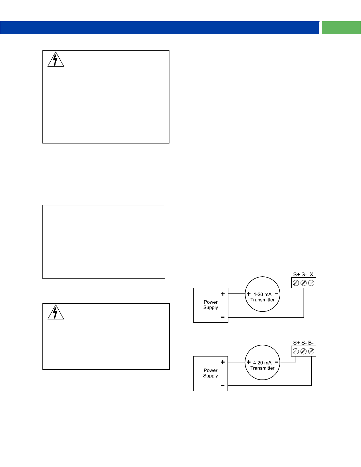
S+
4-20 mA signal input positive
terminal connection
S-
4-20 mA signal return/negative
terminal connection
X
Not connected (no backlight option)
B-
4-20 mA signal return/negative
terminal when using the installed
loop powered backlight option
WARNING
Observe all safety regulations. Electrical
wiring should be performed in accordance
with all agency requirements and applicable
national, state, and local codes to prevent
damage to the meter and ensure personnel
safety.
Connections
To access the connectors, remove the enclosure
cover and unscrew the two captive stainless
steel screws. Remove the meter assembly from
the enclosure. Signal connections are made to a
three-terminal removable connector on the back
of the meter assembly. Grounding connections
are made to the two ground screws provided on
the base – one internal and one external.
Figure 1. PD663 Meter Assembly, Rear View
4-20 mA Input Connections & Wiring
Diagrams
Signal input connections are made to a threeterminal connector labeled S+|S-|X for models
without a backlight and S+|S-|B- for models with
a backlight. The enclosure also provides one
internal and one external earth grounding screw.
The 4-20 mA input with no backlight has a
maximum voltage drop of 1.7 V and is wired as
shown in Figure 2. The loop-powered backlight
configuration requires a total maximum voltage
drop of 4.7 V. The backlight is recommended for
dim lighting conditions and is enabled when
wired as shown in Figure 3. The enclosure also
provides one internal and one external earth
grounding screw.
See Figure 1 for terminal positions on the rear of
the meter assembly.
Figure 2. PD663 Input Connections without
Backlight
Find Quality Products Online at: [email protected]
www.GlobalTestSupply.com
Figure 3. PD663 Input Connections with
Backlight
7
Page 8
PD663 Explosion-Proof NEMA 4X, IP68 Loop-Powered Meter Instruction Manual
There is no need to recalibrate the meter for
milliamps when first received from the factory.
The meter is factory calibrated for milliamps
prior to shipment. The calibration equipment
is traceable to NIST standards.
For Quick User Interface Reference go to
page 16
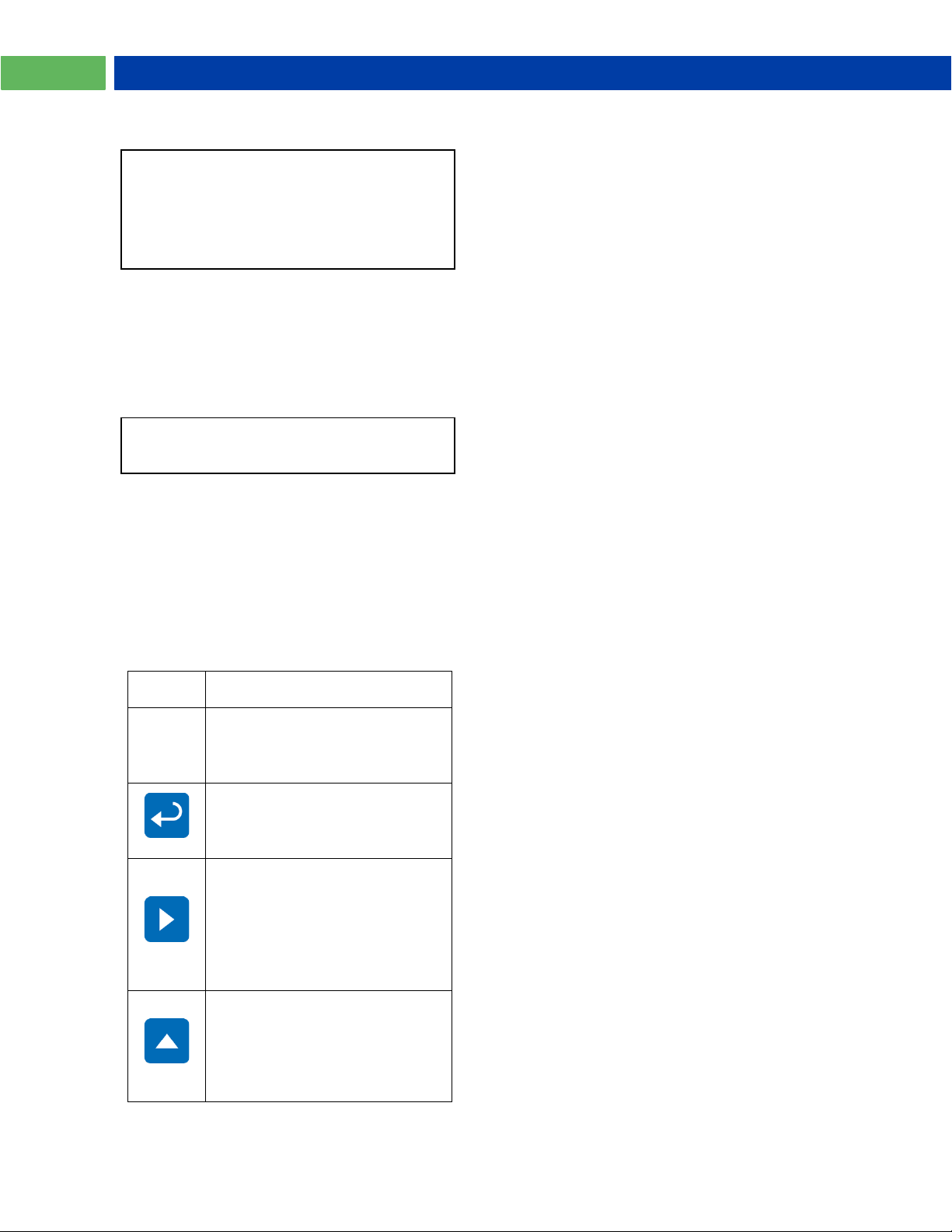
Button/
Symbol
Description
MENU
Menu button to enter
programming mode. Press and
hold for 5 seconds to access the
Advanced features of the meter.
ENTER
Enter button to access a menu
or accept a setting.
RESET
Right arrow to scroll through the
menus or move to the next digit
or decimal position during
programming.
Resets the Max or Min display
value when pressed while
showing Max or Min value.
MAX
Up arrow to scroll through the
menus, decimal point, or to
increment the value of a digit.
Displays the Max then Min
display values when pressed
during normal run mode.
Setup and Programming
Overview
There are no jumpers involved in the setup
process of the meter.
Setup and programming is done through the
front panel buttons.
After all connections have been completed and
verified, apply power to the loop.
Buttons and Display
Setting Numeric Values
The numeric values are set using the Right and
Up arrow buttons. Press the Right arrow to
select next digit and the Up arrow to increment
digit. The two left-most digits on the display are
set as a single digit, able to display -19 to 29.
The digit being changed blinks.
Press the Enter button, at any time, to accept a
setting or Menu button to exit without saving
changes.
The decimal point is set using the Right or Up
arrow button in the Setup-decimal point menu.
Programming the Meter
It is very important to read the following
information, before proceeding to program the
meter:
There is no need to recalibrate the meter for
milliamps when first received from the factory.
The meter is factory calibrated for milliamps
prior to shipment. The calibration equipment is
traceable to NIST standards.
Use the Scale (SCL) menu to enter scale
parameters without applying a live signal.
Alternatively, use the Calibrate (CAL) menu to
apply a signal from a calibrator or a 4-20 mA
transmitter to calibrate the meter.
Inputs may be calibrated or scaled to any
display within the range of the meter.
Additional parameters, not needed for most
applications, are viewed and programmed with
the Advanced features menu, see Advanced
Features Menu, page 11.
Find Quality Products Online at: [email protected]
8
www.GlobalTestSupply.com
Page 9
PD663 Explosion-Proof NEMA 4X, IP68 Loop-Powered Instruction Manual
26.62 dP SCl CAL
Run
Mode
Display
Parameter
Action/Setting
dp
Decimal
point
Set decimal point
SCL
Scale
Enter the Scale
menu
Npt
Number of
Points
Set number of
linearization
points
in1
Scale
Input 1
Input signal 1
value (mA)
D1
Scale
Display 1
Scaled value for
input 1
in2
Scale
Input 2
Input signal 2
value (mA)
D2
Scale
Display 2
Scaled value for
input 2
CAL
Calibrate
Enter the
Calibrate menu
Npt
Number of
Points
Set number of
linearization
points
in1
Calibrate
Input 1
Read input
signal 1
D1
Calibrate
Display 1
Enter value for
input 1
in2
Calibrate
Input 2
Read input
signal 2
D2
Calibrate
Display 2
Enter value for
input 2
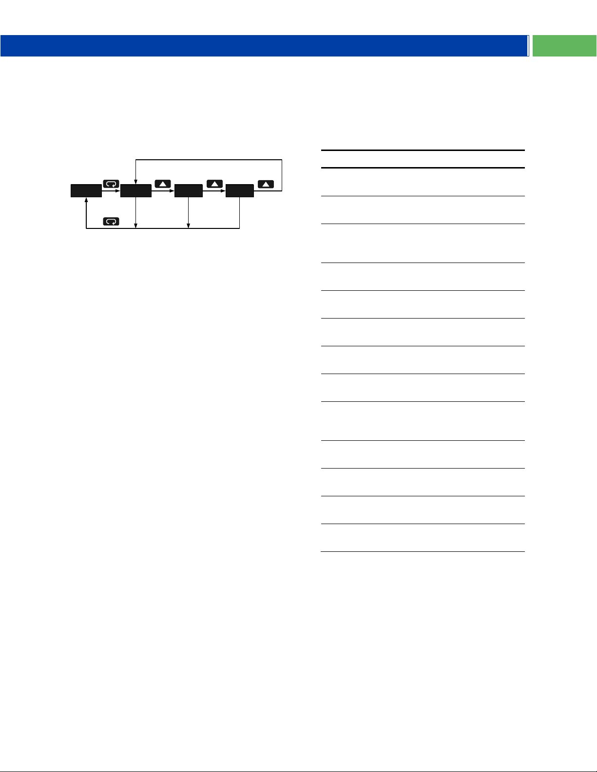
Main Menu
The main menu consists of the most commonly
used functions: Decimal Point Location, Scale,
and Calibration.
Press Menu button to enter Programming Mode
then press the Up Arrow button to scroll through
the main menu.
Press Menu, at any time, to exit and return to
Run Mode. Changes made to settings prior to
pressing Enter are not saved.
Changes to the settings are saved to memory
only after pressing Enter.
The display moves to the next menu every time
a setting is accepted by pressing Enter.
Main Menu Display Functions &
Messages
The meter displays various functions and
messages during setup, programming, and
operation. The following table shows the main
menu functions and messages in the order they
appear in the menu.
Find Quality Products Online at: [email protected]
www.GlobalTestSupply.com
9
Page 10
PD663 Explosion-Proof NEMA 4X, IP68 Loop-Powered Meter Instruction Manual
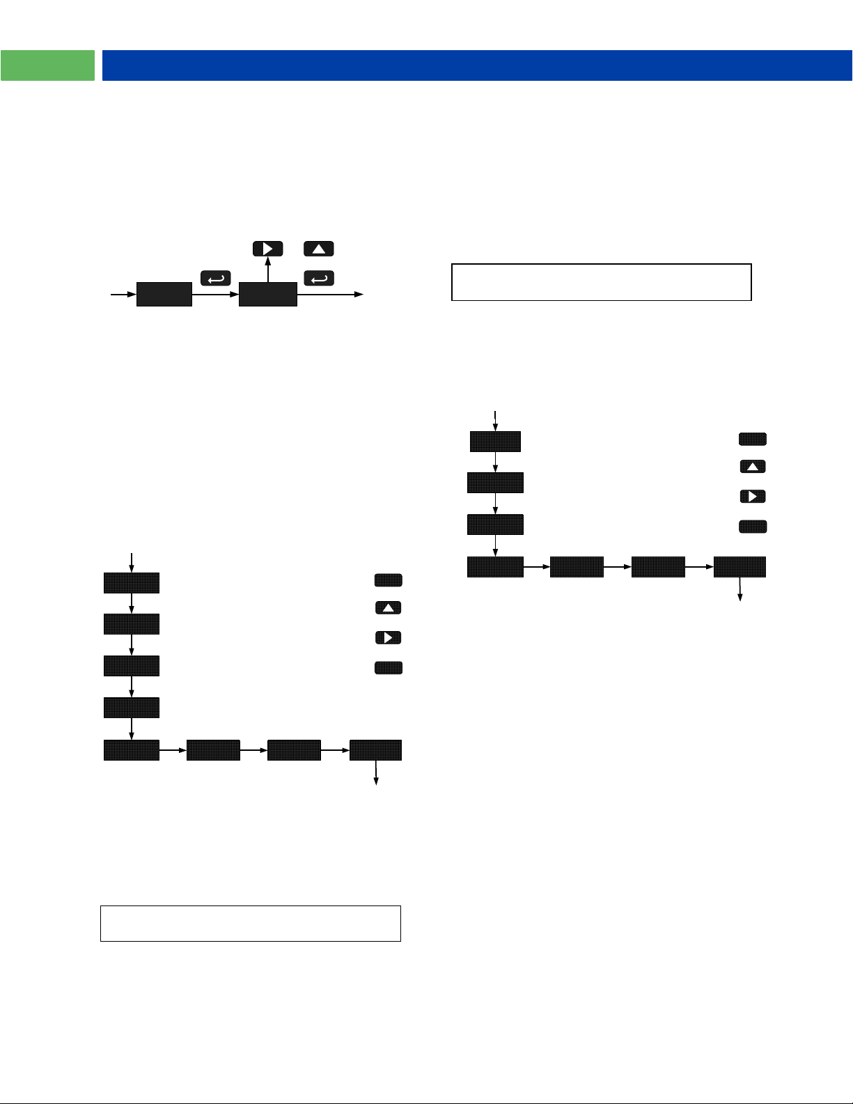
Setting the Decimal Point (dP)
dP dd.dd
or
Select Decimal Point
Next
For instructions on how to program numeric
values see Setting Numeric Values, page 8
To scale the meter without a signal source
refer to Scaling the Meter (SCL), page 10.
d1
Press Enter to
Accept Setting
in2
Scale
Input 2
in1
Set Input 1
Value
SCL
ENTER
04.00
Set Display 1
Value
Press Up to
Set Digit Value
Press Right to
Select Next Digit
Press Menu to
Exit at any Time
000.0
MENU
npt
002
Number of Points menu
not displayed for square
root input conditioning.
Set Number of
Scale Points
d1
Press Enter to
Accept Setting
in2
Calibrate
Input 2
in1
ENTER
Set Display 1
Value
Press Up to
Set Digit Value
Press Right to
Select Next Digit
Press Menu to
Exit at any Time
000.0
MENU
npt
002
Number of Points menu
not displayed for square
root input conditioning.
Set Number of
Scale Points
Cal
Display Flashes
Accepting Input
Decimal point may be set with up to three
decimal places or with no decimal point at all.
Pressing the Right or Up arrow moves the
decimal point one place to the right until no
decimal point is displayed, then it moves to the
left most position.
Minimum Input Span
The minimum input span is the minimum
difference between input 1 and input 2 signals
required to complete the calibration or scaling of
the meter. The minimum span is 0.40 mA.
If the minimum span is not maintained, the
meter reverts to input 2, allowing the appropriate
input signals to be applied.
Calibrating the Meter (
Cal
)
The meter can be calibrated to display the
process in engineering units by applying the
appropriate input signal and following the
Scaling the Meter (
SCL
)
The 4-20 mA input can be scaled to display the
process in engineering units.
calibration procedure.
The use of a calibrated signal source is strongly
recommended.
A signal source is not needed to scale the
meter; simply program the inputs and
corresponding display values.
If using linear signal input conditioning, enter the
number of scale points (2-32), followed by the
input values and display values. If using square
root signal input conditioning, the number of
points input menu will not be present.
Press the Up arrow button to scroll to the
Calibration menu (CAL) and press Enter.
If using linear signal input conditioning, enter the
number of calibration points (2-32).
The meter displays in1. Apply a known signal
and press Enter. The display will flash while
accepting the signal.
When the meter displays d1, press Enter. Enter
a corresponding display value for the signal
input, and press Enter to accept.
The meter displays in2. Apply a known signal
Number of Points (
Set the number of linearization points used in
Find Quality Products Online at: [email protected]
the Scale menu. 2 to 32 points may be used.
The Scale menu is entered after entering the
number of points.
10
npt
)
and press Enter. The display will flash while
accepting the signal.
When the meter displays d2, press Enter. Enter
a corresponding display value for the signal
input, and press Enter to accept.
www.GlobalTestSupply.com
Page 11
PD663 Explosion-Proof NEMA 4X, IP68 Loop-Powered Instruction Manual
Display
Parameter
Action/Setting
Fnc
Input
Function
Set linear or
square root input
conditioning
function
Lnr
Linear
Set linear scaling
Sqr
Square
Root
Set square root input conditioning
function
info
Information
Enter the
Information menu
Sft
Software
Information
Software release
number
ver
Version
Meter firmware
version
*C
Calibration
Temp (°C)
Temperature at
time of Icalibration (°C)
*F
Calibration
Temp (°F)
Temperature at
time of Icalibration (°F)
FIL
Filter
Set filter function
level
ICAL
I-Calibration
Internal master
factory calibration
rst
Reset
Defaults
Restore factory
default parameter
settings
Press Enter to Access Menu
or to Accept Setting
ICAL
FIL
ENTER
MENU
Press Up to Scroll Menu and
to Increment Digit Value
Press Menu to Exit at any Time
inFo
MENU
Press and hold for five seconds
26.62
Run Mode
fnc
Re-calibrating the Internal Calibration
Reference (
The Internal Calibration (ICAL) menu, located in
the Advanced features menu, is used to
recalibrate the internal calibration reference.
Recalibration is recommended at least every
twelve months. Refer to Internal Calibration
(ICal), page 12 for instructions.
ICal
)
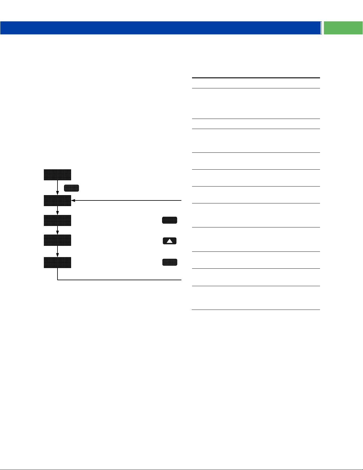
Advanced Features Menu
To simplify the setup process, functions not
needed for most applications are located in the
Advanced features menu. Press and hold the
Menu button for five seconds to access the
Advanced features menu
Advanced Features Menu & Display
Messages
The following table shows the Advanced
features menu functions and messages in the
order they appear in the menu.
Find Quality Products Online at: [email protected]
11
www.GlobalTestSupply.com
Page 12
PD663 Explosion-Proof NEMA 4X, IP68 Loop-Powered Meter Instruction Manual
There is no need to recalibrate the meter for
milliamps when first received from the factory.
The meter is factory calibrated for milliamps
prior to shipment. The calibration equipment
is traceable to NIST standards.
Notes:
The signal source must have a full-scale
accuracy of 0.01% or better between 4 and
20 mA in order to maintain the specified
accuracy of the meter.
Allow the meter to warm up for at least
15 minutes before performing the internal
calibration procedure.
Signal Input Conditioning Function
Fnc
(
)
The PD663 provides linear and squar root signal
input conditioning functions for inputs from linear
and non-linear transmitters.
Linear (
Meters are set up at the factory for linear
function using two-point linearization. Multi-point
linearization with up to 32 points may be used.
The linear function provides a display that is
linear with respect to the input signal between
each set of input points.
Square Root (
The square root function is used to linearize the
signal from a differential pressure transmitter
and display flow rate in engineering units.
Lnr
)
sqr
)
Information Menu (info)
The Information menu is located in the
Advanced features menu, to access Information
menu see Advanced Features Menu, page 11.
It shows software identification number, version
number, and calibration temperatures. To
determine the software version of a meter:
Go to the Information menu (info) and press
Enter button.
The meter will automatically scroll through the
software release number and software version.
The meter temperatures at the time of last
internal calibration in °C and °F are displayed for
calibration troubleshooting. Pressing the Enter,
Right, or Up buttons will progress the
information display.
Following the information display, the meter will
exit the Advanced features menu and return to
run mode.
Internal Calibration (
The internal calibration allows the user to scale
the meter without applying a signal. The use of a
calibrated signal source is necessary to perform
the internal calibration of the meter. Check
calibration of the meter at least every
12 months.
The Internal calibration menu is part of the
Advanced features menu.
Press and hold the Menu button for 5 seconds
to enter the Advanced features menu. Press the
Up arrow button to scroll to the Internal
Calibration menu (ICAL) and press Enter.
The meter displays 4.00 mA. Apply a 4.00 mA
signal and press Enter. The display flashes for a
moment while the meter is accepting the signal.
After the signal is accepted, the meter displays
20.00 mA. Apply a 20.00 mA signal and press
Enter. The display flashes for a moment while
the meter is accepting the signal.
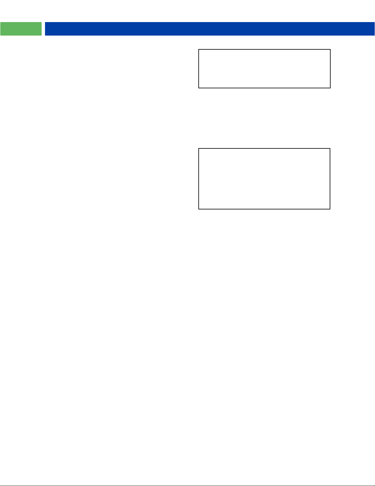
ICal
)
Input Signal Filter (
The noise filter is available for unusually noisy
signals that cause an unstable process variable
display. The noise filter averages the input
signal over a certain period. The filter level can
be set to low (LO), high (HI), or off (OFF). The
higher the filter setting, the longer the averaging
time and so the longer the display may take to
find its final value.
The filter contains a noise filter bypass feature
so that while small variations in the signal will be
filtered out, large, abrupt changes to the input
signal are displayed immediately.
Find Quality Products Online at: [email protected]
12
FIL
)
www.GlobalTestSupply.com
Error Message (
An error message indicates that the calibration
process was not successful. After the error
message is displayed, the meter will revert to
input 2 calibration settings. The error message
might be caused by inadvertently leaving the
signal at the previous level or not maintaining a
0.40 mA minimum span. Press the Menu button
to cancel the current calibration process if
necessary.
Err
)
Page 13
PD663 Explosion-Proof NEMA 4X, IP68 Loop-Powered Instruction Manual
Button
Symbol
Description
MENU
Press to enter or exit
Programming Mode or exit
Max/Min readings.
ENTER
Press to indefinitely display
Max or Min until Menu button is
pressed.
RESET
Press to reset Max or Min
reading.
MAX
Press to display Max/Min
readings alternately.
Press Up to Display and to
Toggle Between Max & Min
10 Sec Time Out
16.62
Run Mode
HI <LO
Press Enter to Hold Max/Min
Press Right to Reset Max/Min
Press Menu to Exit Max/Min
19.45 5.34
OPERATION
Front Panel Buttons Operation
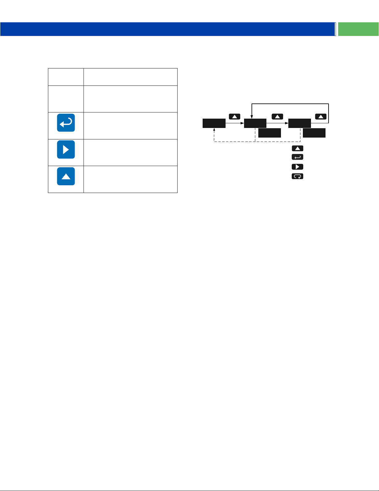
Maximum & Minimum Readings
HI
(
The maximum and minimum (peak & valley)
readings reached by the process are stored in
the meter since the last reset or power-up. The
meter flashes HI or LO to differentiate between
run mode and max/min display.
Press Up arrow button to display maximum
reading since the last reset/power-up.
Press Up arrow again to display the minimum
reading since the last reset/power-up.
Press Enter to continue to display the Max or
Min display reading by disabling the Max/Min
timeout. The meter will continue to track new
Max/Min readings. Press MENU to exit the
Max/Min reading.
If Enter is not pressed, the Max/Min display
reading will continue to flash and time out after
ten seconds. The meter will return to display the
actual reading.
Press Right arrow button while in Max/Min
Mode to reset both Max and Min. Max/Min
display readings are reset to the current reading.
&
LO
)
Find Quality Products Online at: [email protected]
13
www.GlobalTestSupply.com
Page 14
PD663 Explosion-Proof NEMA 4X, IP68 Loop-Powered Meter Instruction Manual
Parameter
Display
Default
Setting
User
Setting
Decimal
point
Dd.dd
2 places
Scale
SCL
Number of
Points
NPT
2
Input 1
in1
4.00 mA
Display 1
D1
4.00 Input 2
in2
20.00 mA
Display 2
D2
20.00
Advanced Features
Input
Conditioning
Function
Fnc
Linear
Filter
FIL
Off
rSt
info
Press and Hold for 5 Sec
Meter Re-
Initializes
Flashing
Display
rSt
FNc
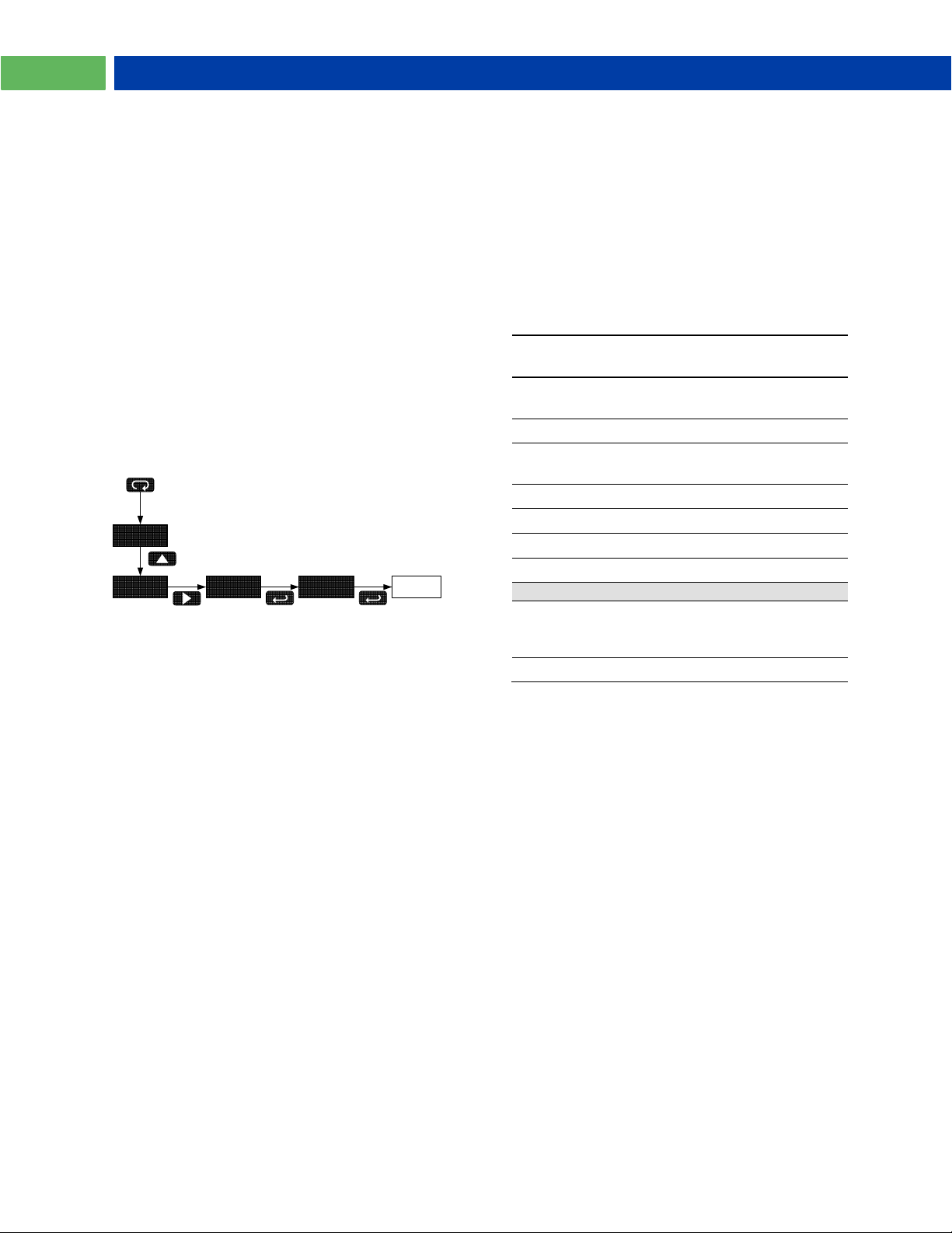
Reset Meter to Factory Defaults
When the parameters have been changed in a
way that is difficult to determine what’s
happening, it might be better to start the setup
process from the factory defaults.
Instructions to load factory defaults:
Enter the Advanced features menu. See
Advanced Features Menu, page 11.
Press Up arrow button to display info menu.
Press Right arrow button when info is shown.
Press Enter button when rSt is shown.
Press Enter again when display flashes rSt.
Note: If Enter is not pressed a second time
within three seconds, rSt will stop flashing and
the last Enter press cancelled.
The meter goes through an initialization
sequence (same as on power-up), and loads the
factory default settings.
Factory Defaults & User
Settings
The following table shows the factory setting for
most of the programmable parameters on the
meter. Next to the factory setting, the user may
record the new setting for the particular
application.
Model: ___________________
S/N: ___________________
Date: ___________________
Find Quality Products Online at: [email protected]
14
www.GlobalTestSupply.com
Page 15
PD663 Explosion-Proof NEMA 4X, IP68 Loop-Powered Instruction Manual
Symptom
Check/Action
No display or faint
display
Check input signal
connections.
Perform hard reset by
shorting S+ and Sterminals.
Rate display
unsteady
Increase filter setting
in Advanced menu.
Meter displays error
message during
calibration (err)
Check signal
connections.
Verify minimum input
span requirements
Meter flashes
2999 or -1999
Check input signal
within scaled range of
2999 and -1999.
Display stuck flashing
a number and HI or
LO
Press Menu to exit
Max/Min
display readings.
Display response is
too slow
Check filter setting to
see if it can be
lowered to LO or OFF.
If the display locks up
or the meter does not
respond at all
Perform hard reset by
shorting S+ and Sterminals.
Backlight does not
appear.
Verify backlight is
installed.
Check signal
connections are as
shown in Figure 3 on
page 7.
Other symptoms not
described above
Call Technical
Support for
assistance.
TROUBLESHOOTING
The rugged design and the user-friendly
interface of the meter should make it unusual for
the installer or operator to refer to this section of
the manual. If the meter is not working as
expected, refer to the recommendations below.
Troubleshooting Tips
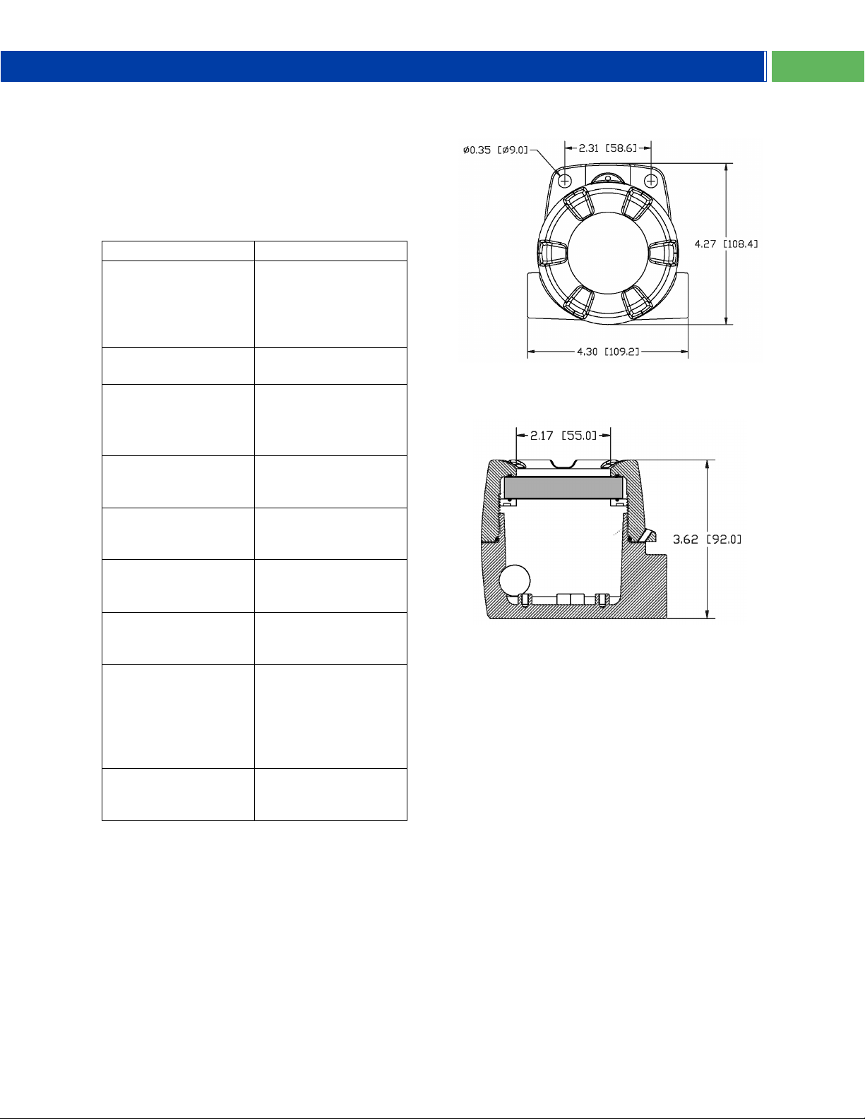
MOUNTING DIMENSIONS
All units: inches [mm]
Figure 4. Enclosure Dimensions – Front View
Figure 5. Enclosure Dimensions – Side Cross
Section View
Note: The supplied conduit plug may extend up
to 0.6 in [15 mm] from the conduit opening when
installed.
Find Quality Products Online at: [email protected]
www.GlobalTestSupply.com
15
Page 16
PD663 Explosion-Proof NEMA 4X, IP68 Loop-Powered Meter Instruction Manual
16
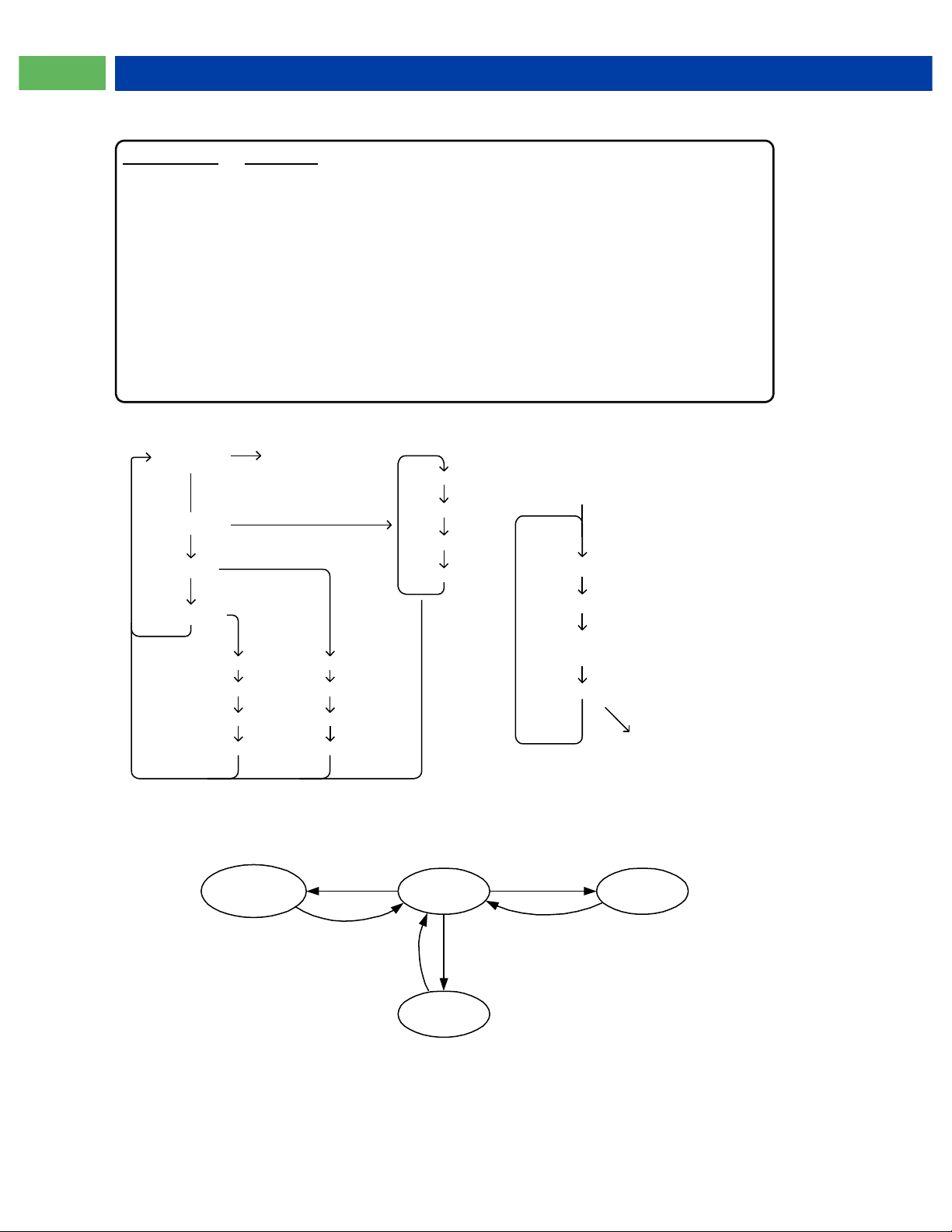
QUICK USER INTERFACE REFERENCE
Scale
Run Mode
Calibrate
Display
Max/Min
dd.dd
in2
d1
in1
ddd.d
dddd
d.ddd
Pushbutton Function
Menu Go to Programming Mode, leave Programming Mode, and Max/Min
Mode. Hold for 5 seconds to access Advanced Features.
Right Arrow Move to next digit or decimal point position. Reset Min/Max.
Up Arrow Move to next selection or increment digit. Go to Max/Min Mode.
Enter Accept selection/value and move to next selection.
Max/Min Mode
While in Run Mode, pressing Up Arrow will initiate Max/Min Mode. Up Arrow toggles
between Max & Min displays, and Right Arrow resets the Max/Min to the current
value. Press Menu or wait 10 seconds to return to Run Mode. Pressing Enter will
disable the 10 second timeout and continuously flash Max or Min.
Decimal
d2
Program
Run
Max &
Min
Advanced
Features
Up Arrow
Menu
Menu
Menu
Menu
Operational Modes
in2
d1
in1
d2
*Access by pressing Right arrow twice
Press & hold Menu for 5
seconds to access Advanced
Features Menu
Filter
Initial
Calibrate
Information
*Factory
Defaults
Hold
Menu
Function
Find Quality Products Online at: [email protected]
www.GlobalTestSupply.com
Page 17

EU Declaration of Conformity
Issued in accordance with ISO/IEC 17050-1:2004 and ATEX Directive 2014/34/EU.
We,
Precision Digital Corporation
233 South Street
Hopkinton, MA 01748 USA
as the manufacturer, declare under our sole responsibility that the product(s),
Model PD663 Series Loop Powered Meter
to which this declaration relates, is in conformity with the European Union Directives shown below:
2014/35/EU Low Voltage Directive
2014/34/EU ATEX Directive
2014/30/EU EMC Directive
2011/65/EU RoHS Directive
This conformity is based on compliance with the application of harmonized or applicable technical
standards and, when applicable or required, a European Union notified body certification.
Standards:
EN 60079-0:2009 EN 60079-1:2007 EN 60079-31:2009
EN 61010-1:2001 EN 61326:2006
The standards EN 60079-0:2009, EN 60079-1:2007, EN 60079-31:2009, EN 61010-1:2001, and EN
61326:2006 are no longer harmonized. The requirements of these standards have been checked
against the harmonized standard EN 60079-0:2012+A11:2013, EN 60079-1:2014, EN 60079-31:2014,
EN 61010-1:2010, and EN 61326:2013 and there were no major technical changes affecting the latest
technical knowledge for the products listed above.
EC Type Examination Certificate: Sira 10ATEX1116X
Product Markings: II 2 G D
Ex d IIC T6 Gb
Ex tb IIIC T85°C Db IP68
Tamb = -40°C to +75°C
ATEX Notified Body for EC Type Examination Certificate:
Sira Certification Service, NB 0518
Unit 6, Hawarden Industrial Park
Hawarden, Deeside, CH5 3US, UK
ATEX Quality Assurance Notification No.:
SIRA 10 ATEX M462
ATEX Notified Body for Quality Assurance:
Sira Certification Service, NB 0518
Unit 6, Hawarden Industrial Park
Hawarden, Deeside, CH5 3US, UK
Signed for and on behalf of Precision Digital Corporation:
Name: Jeffrey Peters
Company: Precision Digital Corporation
Title: President
Date: 02/12/2018
Document No: DoC PD663 {021218}
Find Quality Products Online at: [email protected]
www.GlobalTestSupply.com
Page 18

PD662 General Purpose NEMA 4X, IP68 Loop-Powered Meter Instruction Manual
PRECISION DIGITAL CORPORATION
LIM663_O
SFT054 Ver 1.800 & up
12/18
Find Quality Products Online at: [email protected]
www.GlobalTestSupply.com
 Loading...