

Page 1
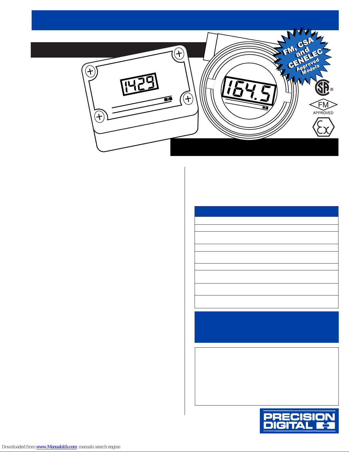
MODEL PD660 NEMA 4X
LOW COST 31/
2 DIGIT LOOP-POWERED METERS
www.predig.com
PRECISION DIGITAL CORPORATION
PHONE (800) 343-1001 • FAX (317) 216-1277
Specifications
INPUT: 4-20 mA @ 24 VDC Maximum
DISPLAY: Sharp, 0.5″ high LCD, 31/2 digits; 1999, user
selectable decimal point
CALIBRATION: 2 Step; non-interacting zero and span
CALIBRATION RANGE: 4 mA input: -500 to +500; 20
mA input: between 20 to 2000 above 4 mA display
MAXIMUM VOLTAGE DROP: 1.5 VDC @ 20 mA;
3.5 VDC @ 20 mA with backlighting option
ACCURACY: ±0.1% of span, ±1 count
CONNECTIONS: Removable screw terminal block
OPERATING TEMPERATURE RANGE: -40 to 80°C
APPROVAL: The PD661-N-EX and PD661-B-EX have
been FM and CSA certified as explosion-proof for Class I,
Division 1, Groups B, C, and D; dust-ignition proof for Class
II, Division 1, Groups E, F, and G; and Class III hazardous
(classified) locations. LCIE (CENELEC) certified as flameproof, EEx d IIC T6.
PD660 ENCLOSURE: High impact-resistant ABS plastic
body, clear ABS plastic cover; NEMA 4X;
1
/2″ conduit hole
provided at base. May be provided on back for panel mounting applications, call factory for details.
PD661 ENCLOSURE: Cast aluminum, approved by FM
and CSA; NEMA 4, 7 and 9; Class I, Groups B, C, and D;
Class II, Groups E, F, and G; and Class III. Two
1
/2″ NPT
holes provided.
LOOP-POWERED BACKLIGHTING OPTION: Factory
installed only. Powered directly off the 4-20 mA loop, no batteries required. The display brightness will increase as the
input signal current increases.
WARRANTY: 1 year parts and labor
EXTENDED WARRANTY: May be extended an additional
12 months by returning the Product Registration Form within
2 months from date of purchase. Go to www.predig.com for
online registration.
Model Description
PD660-N NEMA 4X Loop-Powered Meter
PD660-B NEMA 4X Loop-Powered Meter
with Loop-Powered Backlighting
PD661-N Explosion-Proof Loop-Powered Meter
PD661-B Explosion-Proof Loop-Powered Meter
with Loop-Powered Backlighting
PD661-N-EX FM, CSA, & CENELEC Explosion-Proof Meter
PD661-B-EX FM, CSA, & CENELEC Explosion-Proof Meter
with Loop-Powered Backlighting
PDA6604 Panel Mounting Kit
(Panel Mounting Kit does not provide NEMA 4X seal to the panel)
PDA6845 2″ Pipe Mounting Kit
(Available for PD660 Only)
ORDERING INFORMATION
•
4-20 mA Input
•
31/2 Digit Display
•
Easy Calibration and Installation
• Loop-Powered Backlighting
Option
• Wide Operating Temp Range:
-40 to 80°C
MODEL PD661 EXPLOSION-PROOF
P
R
E
C
IS
IO
N
D
IG
IT
A
L
PRECISION DIGITAL
Please visit the Precision Digital website at
www.predig.com
for complete information on the entire line of Precision Digital
products, technical information and much more.
YOUR LOCAL DISTRIBUTOR IS:
FM, CSA
and
CENELEC
Approved
Models
FM, CSA
and
CENELEC
Approved
Models
Page 2
www.predig.com
LOW COST 31/
2 DIGIT LOOP-POWERED METERS
PRECISION DIGITAL CORPORATION
CORPORATE HEADQUARTERS
19 Strathmore Road • Natick MA • 01760 • USA • Tel: (800) 343-1001 • Fax: (317) 216-1277
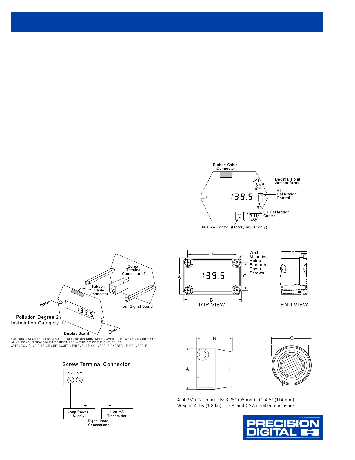
DECIMAL POINT SELECTION
The decimal point jumper array (JP1) is located in the upper
right corner of the display board. Place a jumper across the
bottom pins for a display of 199.9, across the middle pins for
a display of 19.99, and across the top pins for a display of
1.999.
CALIBRA TION
The LO calibration control (R11) is located below the display
and the HI calibration control (R9) is located to the right of the
display.
Apply a 4 mAinput signal and adjust the LO control to display
the desired reading. Next, apply a signal between 16 and 20
mA and adjust the HI control to display the desired reading.
Complete the calibration procedure by making any minor
adjustments to the LO and HI controls.
DIMENSIONS
PD660
PD661
SETUP
The only tools needed for calibration are a calibrated current
source and a screwdriver.
PD660 INSTALLATION
Installation of the PD660 involves removing the display board
and screw terminal connector. It may also be necessary to
remove the input signal board depending on type of conduit
hubs used.
PD661 INSTALLATION
The PD661 has no provisions for wall mounting. Installation
of the unit is accomplished by using the two
1
/2″ NPT conduit
holes provided with
1
/2″ NPT fittings.
DISASSEMBLY
The removable screw terminal connector is located on the
lower circuit board. To access these input terminals it is necessary to remove the display board from the input signal board.
This is done by first removing the enclosure cover. Next,
loosen the 2 screws that hold the display board to the standoffs.
Rotate the display board so the right side comes off the standoff first, proceed to remove the display board from both standoffs. Be careful to avoid contact of the display with rough
surfaces. The display board may be disconnected from the ribbon cable simply by pulling up on the ribbon cable connector
located above the display.
Connect a 4-20 mA input signal to terminal J5 located on the
input signal board as shown below.
When reassembling the circuit boards
be careful NOT to over-tighten
the screws.
Ribbon
Cable
Connector
Display Board
Input Signal Board
Pollution Degree 2
Installation Category II
Screw
Terminal
Connector J5
++
+
--
-
Loop Power
Supply
Signal Input
Connections
SS
4-20 mA
Transmitter
Screw Terminal Connector
A: 4.75″ (121 mm) B: 3.75″ (95 mm) C: 4.5″ (114 mm)
Weight: 4 lbs (1.8 kg) FM and CSA certified enclosure
CAUTION-DISCONNECT FROM SUPPLY BEFORE OPENING. KEEP COVER TIGHT WHILE CIRCUITS ARE
ALIVE. CONDUIT SEALS MUST BE INSTALLED WITHIN 18″ OF THE ENCLOSURE.
ATTENTION-OUVRIR LE CIRCUIT AVANT D’ENLEVEL LE COUVERCLE GARDER LE COUVERCLE BIEN
FERME TANT QUE LES CIRCUITS SONT SOUS TENSION. UN SCELLEMENT DOIT ETRE INSTALLE A
MOINS DE 450 mm DU BOITIER.
CONNECTIONS
A: 3.15″ (80 mm) C: 2.36″ (60 mm) E: 2.56″ (65 mm)
B: 4.33″ (110 mm) D: 3.54″ (90 mm) F: 0.79″ (20 mm)
Weight: 12 oz (340 g)
LIM660-661 Rev C 06/00
Ribbon Cable
Connector
JP1
HI
R9
R11
LO
Balance Control (factory adjust only)
Decimal Point
Jumper Array
HI
Calibration
Control
LO Calibration
Control
D
A
Wall
Mounting
Holes
Beneath
Cover
Screws
C
E
F
TOP VIEW END VIEW
A
B
B
C
 Loading...