

Page 1
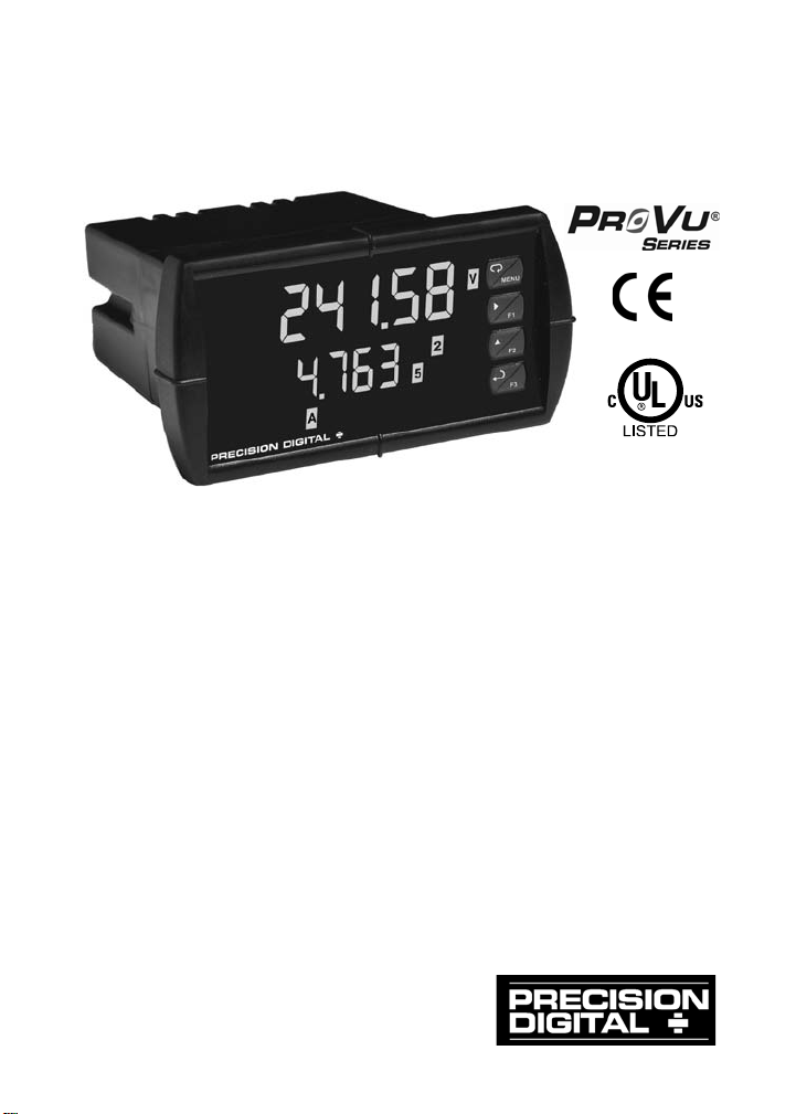
PD6400 High Voltage
and Current Meter
Instruction Manual
• (1) High Voltage and (1) High Current Input
• Multiplication for Apparent Power Calculation
• 0-300 VAC or VDC Voltage Input
• 0-5 AAC or ADC Current Input
• NEMA 4X, IP65 Front
• 85-265 VAC or 12/24 VDC Input Power Models
• Large Dual-Line 6-Digit Display, 0.60" & 0.46"
• Sunlight Readable SunBright Display Models
• Programmable Display & Function Keys
• 2 or 4 Relays + Isolated 4-20 mA Output Options
• External 4-Relay & Digital I/O Expansion Modules
• USB, RS-232 & RS-485 Serial Communication Options
• Modbus
• Configure, Monitor, and Datalog from a PC with
Free MeterView
®
RTU Communication Protocol Standard
®
Pro Software
PRECISION DIGITAL CORPORATION
89 October Hill Road • Holliston MA 01746 USA
Tel (800) 34 3-1 001 • Fax (508) 655-8990
www.predig.com
Page 2
Model PD6400 High Voltage & Current Meter Instruction Manual
CAUTION
WARNING!
WARNING!
This product is not recommended for life support applications
!
Disclaimer
The information contained in this document is subject to change
without notice. Precision Digital makes no representations or
warranties with respect to the contents hereof and specifically
disclaims any implied warranties of merchantability or fitness for a
particular purpose.
Read complete instructions
prior to installation and
operation of the meter.
Risk of electric shock or
personal injury.
or applications where malfunctioning could result in personal
injury or property loss. Anyone using this product for such
applications does so at his/her own risk. Precision Digital
Corporation shall not be held liable for damages resulting from
such improper use.
Limited Warranty
Precision Digital Corporation warrants this product against defects in
material or workmanship for the specified period under
“Specifications” from the date of ship ment from the factor y . Pr eci sion
Digital’s liability under this limited warranty shall not exceed the
purchase value, repair, or replacement of the defective unit.
Registered Trademarks
PROVU® and MeterView® Pro are registered trademarks of Precision
Digital Corporation. All other trademarks mentioned in this document
are the property of their respective owners.
© 2014 Precision Digital Corporation. All rights reserved.
www.predig.com
2
Page 3

Model PD6400 High Voltage & Current Meter Instruction Manual
Table of Contents
INTRODUCTION ------------------------------------------------------------ 6
ORDERING INFORMATION --------------------------------------------- 7
SPECIFICATIONS ---------------------------------------------------------- 8
General ------------------------------------------------------------------------------- 8
Voltage and Current Inputs --------------------------------------------------- 9
Relays ------------------------------------------------------------------------------ 10
Isolated 4-20 mA Transmitter Output ------------------------------------ 11
Modbus® RTU Serial Communications --------------------------------- 12
COMPLIANCE INFORMATION ---------------------------------------- 13
Safety ------------------------------------------------------------------------------- 13
Electromagnetic Compatibility --------------------------------------------- 13
SAFETY INFORMATION ------------------------------------------------ 14
INSTALLATION ------------------------------------------------------------ 14
Unpacking ------------------------------------------------------------------------- 14
Panel Mounting Instructions ------------------------------------------------ 14
MOUNTING DIMENSIONS ---------------------------------------------- 16
Configuration for 12 or 24 VDC Power Option ------------------------ 17
Connections ---------------------------------------------------------------------- 18
Connectors Labeling --------------------------------------------------------- 18
Power Connections ---------------------------------------------------------- 19
Signal Connections ---------------------------------------------------------- 19
Modbus RTU Serial Communications ----------------------------------- 23
Relay Connections ----------------------------------------------------------- 23
Switching Inductive Loads -------------------------------------------------- 24
F4 Digital Input Connections ----------------------------------------------- 25
4-20 mA Output Connections ---------------------------------------------- 25
Analog Output Transmitter Power Supply ------------------------------ 25
External Relay, Analog Output, & Digital I/O Connections --------- 26
Interlock Relay Feature ----------------------------------------------------- 26
SETUP AND PROGRAMMING ---------------------------------------- 27
Front Panel Buttons and Status LED Indicators --------------------- 28
Display Functions & Messages -------------------------------------------- 29
Main Menu ------------------------------------------------------------------------ 33
Setting Numeric Values ------------------------------------------------------ 34
Setting Up the Meter (setup) ------------------------------------------------ 35
Setting the Decimal Point (dEc pt) -------------------------------------- 36
3
Page 4

Model PD6400 High Voltage & Current Meter Instruction Manual
Setting the Input Calibration (InCal) ------------------------------------ 37
Multi-Point Linearization (Linear) ------------------------------------ 38
MeterView® Pro Software ----------------------------------------------- 38
Scaling the Meter without a Signal Source ------------------------- 38
Scaling the Meter for Channel A (SCal-A) ------------------------- 39
Scaling the Meter for Channel V (SCal-v) ------------------------- 39
Error Message (Error) -------------------------------------------------- 40
Calibrating the Meter with External Source------------------------- 40
Calibrating the Meter for Channel A (CAL-A) ----------------------- 41
Calibrating the Meter for Channel V (CAL-v) ----------------------- 41
Setting the Display Parameter & Intensity (dsplay) ----------------- 42
Display Setup Menu --------------------------------------------------------- 43
Setting the Input Units or Custom Tags (units)---------------------- 44
Setting the Relay Operation (relay)-------------------------------------- 45
Setting the Relay Assignment (asSign) -------------------------------- 46
Setting the Relay Action ---------------------------------------------------- 47
Programming Set and Reset Points ------------------------------------- 48
Setting Fail-Safe Operation ------------------------------------------------ 48
Programming Time Delay -------------------------------------------------- 48
Relay Action for Loss of Input (Loop Break) --------------------------- 48
Relay and Alarm Operation Diagrams ----------------------------------- 49
High Alarm Operation (Set > Reset) ------------------------------------- 49
Low Alarm Operation (Set < Reset)-------------------------------------- 50
High Alarm with Fail-Safe Operation (Set > Reset) ------------------ 51
Low Alarm with Fail-Safe Operation (Set < Reset) ------------------- 52
Pump Alternation Control Operation ------------------------------------- 52
Relay Sampling Operation ------------------------------------------------- 53
Signal Loss or Loop Break Relay Operation --------------------------- 54
Time Delay Operation ------------------------------------------------------- 55
Relay Operation Details ------------------------------------------------------ 56
Overview ------------------------------------------------------------------------ 56
Relays Auto Initialization ---------------------------------------------------- 56
Fail-Safe Operation ---------------------------------------------------------- 56
Front Panel LEDs ------------------------------------------------------------- 57
Latching and Non-Latching Relay Operation -------------------------- 57
Non-Latching Relay (Auto)------------------------------------------------- 58
Non-Latching Relay (A-man) -------------------------------------------- 58
Latching Relay (LatcH) ----------------------------------------------------- 58
Latching Relay (Lt-Clr) ---------------------------------------------------- 59
Acknowledging Relays ------------------------------------------------------ 59
Pump Alternation Control Applications (Altern) --------------------- 60
Setting Up the Interlock Relay (Force On) Feature ------------------ 60
4
Page 5

Model PD6400 High Voltage & Current Meter Instruction Manual
Scaling the 4-20 mA Analog Output (Aout) ---------------------------- 61
Reset Menu (reset) ------------------------------------------------------------ 62
Control Menu (Contrl) -------------------------------------------------------- 62
Setting Up the Password (pass) ------------------------------------------- 63
Protecting or Locking the Meter ------------------------------------------- 63
Making Changes to a Password Protected Meter -------------------- 64
Disabling Password Protection -------------------------------------------- 64
Advanced Features Menu ---------------------------------------------------- 65
Advanced Features Menu & Display Messages ---------------------- 65
Noise Filter (filter) -------------------------------------------------------- 68
Noise Filter Bypass (bypass) ---------------------------------------------- 68
Rounding Feature (round) ------------------------------------------------- 69
Modbus RTU Serial Communications (serial) ---------------------- 69
Select Menu (SElect) ------------------------------------------------------- 70
Multi-Point Linearization (Linear) ---------------------------------------- 71
Math Function (math) ----------------------------------------------------- 72
Math Constants (Const) ---------------------------------------------------- 72
Low-Flow Cutoff (CutofF) -------------------------------------------------- 72
Analog Output Programming (AoutPr) ---------------------------------- 72
Programmable Function Keys User Menu (user) -------------------- 74
Internal Calibration (ICAL) -------------------------------------------------- 76
Meter Copy Function (Copy) ----------------------------------------------- 79
METER OPERATION ----------------------------------------------------- 81
Front Panel Buttons Operation -------------------------------------------- 81
Function Keys Operation ---------------------------------------------------- 82
F4 Operation --------------------------------------------------------------------- 82
Maximum/Minimum Readings ---------------------------------------------- 82
TROUBLESHOOTING ---------------------------------------------------- 83
Diagnostics Menu (diag) ----------------------------------------------------- 83
Determining Software Version -------------------------------------------- 83
Reset Meter to Factory Defaults ------------------------------------------- 84
Factory Defaults & User Settings ----------------------------------------- 85
Alphabetical List of Display Functions & Messages --------------- 89
Troubleshooting Tips --------------------------------------------------------- 94
5
Page 6

Model PD6400 High Voltage & Current Meter Instruction Manual
Table of Figures
Figure 1. 1/8 DIN Panel Cutout Dimensions ..................................... 15
Figure 2. Panel Mounting Details ...................................................... 15
Figure 3. Meter Dimensions - Side View ........................................... 16
Figure 4. Meter Dimensions - Top View ............................................ 16
Figure 5. Jumper Configuration for 12/24 VDC Power .................... 17
Figure 6. Connector Labeling for Fully Loaded PD6400 ................. 18
Figure 7. Power Connections ............................................................ 19
Figure 8. AC Voltage Input Connection ............................................ 19
Figure 9. DC Voltage Input Connections .......................................... 20
Figure 10. AC Current Connections .................................................. 20
Figure 11. AC Current Transformer Connections ............................ 20
Figure 12. DC Current Connections .................................................. 21
Figure 13. AC Current and Voltage Connections ............................ 21
Figure 14. AC Current Transformer and Voltage Connections ...... 22
Figure 15. DC Current and Voltage Connections ............................ 22
Figure 16. Relay Connections ........................................................... 23
Figure 17. AC and DC Loads Protection........................................... 24
Figure 18. Low Voltage DC Loads Protection .................................. 24
Figure 19. F4 Digital Input Connections ........................................... 25
Figure 20. 4-20 mA Output Connections .......................................... 25
Figure 21. Interlock Connections ...................................................... 26
Figure 22. Acknowledge Relays w/Function Key or Digital Input .. 59
INTRODUCTION
The PROVU® PD6400 is a multipurpose, easy to use high voltage and current input
meter ideal for measuring direct voltage and current or the output from voltage shunts
and current transformers. It has one 0-300 VAC or VDC voltage input and one 0-5
AAC or ADC current input. The meter may be used wit h a single voltage or current
input, or to measure both simultaneously. A math channel P calculates apparent
power as the product of the voltage and current inputs.
The PD6400 can display voltage, current, and apparent power. The dual line display
can display any two parameters simultaneously, or can alternate between any
parameters as well as their programmable units and tags.
A fully loaded PD6400 meter has the following: four SPDT relays, 4-20 mA output, and a
24 VDC power supply. The PD6400 capabilities may be enhanced by adding the
following external expansion modules: four SPST relays; creating an eight-relay meter,
two digital I/O modules with four inputs and four outputs each, serial communication
adapters for use with MeterView Pro or Modbus RTU, and a dual 4-20 mA expansion
module; for a total of three 4-20 mA a nalog outpu t s.
6
Page 7
Model PD6400 High Voltage & Current Meter Instruction Manual
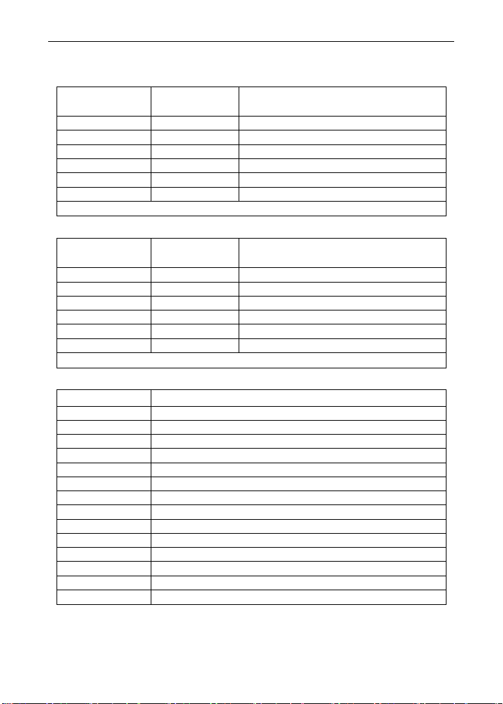
PD6400-6R0
PD6400-7R0
No options
PD6400-6R4
PD6400-7R4
4 relays (PD1104*)
PD6400-6R5
PD6400-7R5
2 relays & 4-20 mA output (PD1105*)
PD6400-6R7
PD6400-7R7
4 relays & 4-20 mA output (PD1107*)
85-265 VAC
12/24 VDC
PD6400-6H0
PD6400-7H0
No options
PD6400-6H2
PD6400-7H2
2 relays (PD1102*)
PD6400-6H3
PD6400-7H3
4-20 mA output (PD1103*)
PD6400-6H4
PD6400-7H4
4 relays (PD1104*)
Model
Description
PDA1002
DIN rail mounting kit for two expansion modules
PDA1004
4 SPST (Form A) relays
PDA1011
Dual 4-20 mA expansion module
PDA1044
4 digital inputs & 4 digital outputs (2 may be connected)
PDA1485
RS-485 serial adapter
PDA7485-I
RS-232 to RS-422/485 isolated converter
PDA7485-N
RS-232 to RS-422/485 non-isol ated con verter
PDA8008
USB serial adapter
PDA8232-N
USB to RS-232 non-isolated converter
PDA8485-I
USB to RS-422/485 isolated converter
ORDERING INFORMATION
Standard Models
85-265 VAC
Model
PD6400-6R2 PD6400-7R2 2 relays (PD1102*)
PD6400-6R3 PD6400-7R3 4-20 mA output (PD1103*)
*Model number for replacement option card.
SunBright Display Models
12/24 VDC
Model
Options Installed
Model
PD6400-6H5 PD6400-7H5 2 relays & 4-20 mA output (PD1105*)
PD6400-6H7 PD6400-7H7 4 relays & 4-20 mA output (PD1107*)
*Model number for replacement option card.
Model
Options Installed
Accessories
PDA1200 Meter copy cable
PDA1232 RS-232 serial adapter
PDA8485-N USB to RS-422/485 non-isolated converter
PDX6901 Suppressor (snubber): 0.01 µF/470 Ω, 250 VAC
7
Page 8

Model PD6400 High Voltage & Current Meter Instruction Manual
The main (Big) and secondary (Little) displays may be
SPECIFICATIONS
Except where noted all specifications apply to operation at +25°C.
General
DISPLAY
DISPLAY
INTENSITY
DISPLAY
UPDATE RATE
OVERRANGE
UNDERRANGE
DISPLAY
ASSIGNMENT
PROGRAMMING
METHODS
NOISE FILTER
FILTER BYPASS
RECALIBRATION
MAX/MIN
DISPLAY
PASSWORD
NON-VOLATILE
MEMORY
Upper display: 0.60" (15 mm) high, red LEDs
Lower display: 0.46" (12 mm) high, red LEDs
6 digits each (-99999 to 999999), with lead zero blanking
Eight user selectable intensity levels
5/second (200 ms)
Display flashes
Display flashes
assigned to process values for Channels A (Ch-A, current),
V (Ch-V, voltage), or P (Ch-P, apparent power); toggle
between (Ch-A & Ch-V, Ch-A & Ch-P, Ch-V & Ch-P, and
Ch-A, Ch-V, & Ch-P); relay set points; max and/or min
values for CH-A, Ch-V, o r Ch-P; CH-A and uni ts; Ch-V and
units; Ch-P and units; or Modbus input. The lower display
may also be set to show engineering units or be off, with no
display.
Four front panel buttons, digital inputs, PC and MeterView Pro
software, Modbus registers, or cloning using Copy function.
Programmable from 2 to 199 (0 will disable filter)
Programmable from 0.1 to 99.9% of calibrated span
All ranges are calibrated at the factory. Recalibration is
recommended at least every 12 months.
Max/min readings reached by each displayed input type are
stored until reset by the user or until power to the meter is
cycled.
Three programmable passwords restrict modification of
programmed settings.
Pass 1: Allows use of function keys and digital inputs
Pass 2: Allows use of function keys, digital inputs and editing set/reset points
Pass 3: Restricts all programming, function keys, and digital inputs.
All programmed settings are stored in non-volatile memory
for a minimum of ten years if power is lost.
999999
-99999
8
Page 9

Model PD6400 High Voltage & Current Meter Instruction Manual
HIGH VOLTAGE
INPUT
One high voltage input (Channel V)
0-300 VDC or VAC; Switch Selectable, Modbus PV (Slave)
HIGH CURRENT
INPUT
One high current input (Channel A)
0-5 AAC or ADC; Switch Selectable, Modbus PV (Slave)
CHANNELS
Channel A, Channel V, Channel P (Math Channel for
Apparent Power)
AC/DC
SELECTION
Switch selectable for AC or DC inputs. Channels A and V
share AC/DC selection.
APPARENT
POWER MATH
Apparent power P calculated as P = ((A * V) + C) * F
PROGRAMMABLE CONSTANTS
Constant F (Factor): 0.001 to 999.999, default: 1.000
POWER
OPTIONS
FUSE
ISOLATION
OVERVOLTAGE
CATEGORY
ENVIRONMENTAL
CONNECTIONS
ENCLOSURE
MOUNTING
TIGHTENING
TORQUE
OVERALL
DIMENSIONS
WEIGHT
WARRANTY
85-265 VAC 50/60 Hz, 90-265 VDC, 20 W max
or jumper selectable 12/24 VDC ± 10%, 15 W max
Required external fuse: UL Recognized, 5 A max, slow
blow; up to 6 meters may share one 5 A fuse
500 V AC/DC potential allowed between voltage and current
input channels. Channels isolated by 3 MΩ impedance
4 kV input/output-to-power line
500 V input-to-output or output-to-P+ supply
Installation Overvoltage Category II:
Local level with smaller transient overvoltages than
Installation Overvoltage Category III.
Operating temperature range: -40 to 65°C
Storage temperature range: -40 to 85°C
Relative humidity: 0 to 90% non-condensing
Removable screw terminal blocks accept 16 to 28 AWG
wire, RJ45 for external relays, digital I/O, and serial
communication adapters.
1/8 DIN, high impact plastic, UL 94V-0, color: black
1/8 DIN panel cutout required:
3.622" x 1.772" (92 mm x 45 mm)
Two panel mounting bracket assemblies are provided.
Screw terminal connectors: 5 lb-in (0.56 Nm)
4.68" x 2.45" x 5.64" (119 mm x 62 mm x 143 mm)
(W x H x D)
9.5 oz (269 g)
3 years parts & labor
Voltage and Current Inputs
Constant C (Adder): -99.999 to 999.999, default: 0.000
9
Page 10

Model PD6400 High Voltage & Current Meter Instruction Manual
ACCURACY
ADC: 0.03% Full Scale ±1 count,
range: 10-100% of calibrated span
TEMPERATURE
DRIFT
0.005% of calibrated span/°C max from -40 to 65°C ambient
SIGNAL INPUT
CONDITIONING
Linear, square root, programmable exponent, or
round horizontal tank volume calculation
MULTI-POINT
LINEARIZATION
LOW-FLOW
CUTOFF
0-999999 (0 disables cutoff function). Independent for
DECIMAL POINT
Up to five decimal places or none:
,
CALIBRATION
RANGE
A +/- 0-5 ADC
0-5 AAC
+/- 0.005 ADC
0.010 AAC
V +/- 0-300 VDC
+/- 0.1 VD C
An error message will appear if the input 1 and input 2
signals are too close together.
INPUT
Current Input: 50 - 100 Ω
INPUT
Voltage input protected up to 500 VDC
F4 DIGITAL
CONTACTS
3.3 VDC on contact. Connect normally open contacts
F4 DIGITAL
LOGIC LEVELS
Logic High: 3 to 5 VDC
AAC: 0.1% Full Scale ±1 count,
VDC: 0.05% Full Scale ±1 count,
VAC: 0.15% Full Scale ±1 count,
square root & programmable exponent accuracy
2 to 32 points for Channel A and V
Channel A and V.
d.ddddd, d.dddd, d.ddd, d.dd, d.d
Input
Channel
IMPEDANCE
OVERLOAD
INPUT
INPUT
Voltage Input: Greater than 3 MΩ
Current input protected up to 10 A by a 10A/300V fast
acting non-resettable fuse
Fuse is NOT resettable after a fault; unit must be factory
reconditioned.
across F4 to COM.
Logic Low: 0 to 1.25 VDC
Relays
RATING
NOISE
SUPPRESSION
2 or 4 SPDT (Form C) internal and/or 4 SPST (Form A)
external; rated 3 A @ 30 VDC and 125/250 VAC resistive
load; 1/14 HP (≈ 50 W) @ 125/250 VAC for inductive loads
Noise suppression is recommended for each relay contact
switching inductive loads; see page 24 for details.
or
dddddd
Input Range Minimum Span
0-300 VAC
Input 1 & Input 2
0.3 VAC
10
Page 11

Model PD6400 High Voltage & Current Meter Instruction Manual
1. Automatic reset only (non-latching), when the input
RELAY
ASSIGNMENT
DEADBAND
HIGH OR LOW
ALARM
RELAY
OPERATION
RELAY RESET
TIME DELAY
FAIL-SAFE
OPERATION
BREAK
CONDITION
OPERATION
AUTO
INITIALIZATION
Each relay independently assigned to Ch-A, Ch-V, CH-P, or
Modbus
0-100% of span, user programmable
User may program any alarm for high or low trip point.
Unused alarm LEDs and relays may be disabled (turn off).
Automatic (non-latching)
Latching (required manual acknowledge)
Pump alternation control (2 to 8 relays)
Sampling (based on time)
Off (disable unused relays and enable Interlock feature)
Manual on/off control mode
User selectable via front panel buttons, digital inputs, or PC
passes the reset point.
2. Automatic + manual reset at any time (non-latching)
3. Manual reset only, at any time (latching)
4. Manual reset only after alarm condition has cleared (L)
Note: Front panel button or digital input may be assigned to
acknowledge relays programmed for manual reset.
0 to 999.9 seconds, on & off relay time delays
Programmable and independent for each relay
Programmable and independent for each relay.
Note: Relay coil is energized in non-alarm condition.
In case of power failure, relay will go to alarm state.
Relay condition when sensor break detected.
Programmable independently for each relay as On, Off, or
Ignore (maintain last condition).
When power is applied to the meter, relays will reflect the
state of the input to the meter.
Isolated 4-20 mA Transmitter Output
OUTPUT
SOURCE
SCALING RANGE
CALIBRATION
ANALOG OUT
PROGRAMMING
ACCURACY
Process channel A, V, or P, max or min for channel A, V, or
highest or lowest max or min of A and V, set points 1-8,
Modbus input, or manual control mode
1.000 to 23.000 mA for any display range
Factory calibrated: 4.000 to 20.000 = 4-20 mA output
23.000 mA maximum for all parameters:
Overrange, underrange, max, min, and break
± 0.1% of span ± 0.004 mA
11
Page 12

Model PD6400 High Voltage & Current Meter Instruction Manual
EXTERNAL LOOP
TEMPERATURE
DRIFT
ISOLATED
TRANSMITTER
POWER SUPPLY
POWER SUPPLY
OUTPUT LOOP
RESISTANCE
0.4 µA/°C max from 0 to 65°C ambient,
0.8 µA/°C max from -40 to 0°C ambient
Note: Analog output drift is separate from input drift.
Terminals I+ & R: 24 VDC ± 10% @ 40mA. May be used to
power the 4-20 mA output or other devices. Refer to Figure
6 on page 18 and Figure 20 on page 25.
35 VDC maximum
Power supply Minimum Maximum
24 VDC
35 VDC (external)
10 Ω 700 Ω
100 Ω 1200 Ω
Modbus® RTU Serial Communications
SLAVE ID
BAUD RATE
TRANSMIT
TIME DELAY
DATA
PARITY
BYTE-TO-BYTE
TIMEOUT
TURN AROUND
DELAY
Note: Refer to the PROVU® Modbus Register Tables located at www.predig.com
for details.
1 – 247 (Meter address)
300 – 19,200 bps
Programmable between 0 and 199 ms
8 bit (1 start bit, 1 or 2 stop bits)
Even, Odd, or None with 1 or 2 stop bits
0.01 – 2.54 second
Less than 2 ms (fixed)
12
Page 13

Model PD6400 High Voltage & Current Meter Instruction Manual
IMMUNITY
Magnetic Field
COMPLIANCE INFORMATION
Safety
UL & c-UL LISTED USA & Canada
UL FILE NUMBER
FRONT PANEL
LOW VOLTAGE
DIRECTIVE
Electromagnetic Compatibility
EMISSIONS
Radiated
Emissions
AC Mains
Conducted
Emissions
RFI - Amplitude
Modulated
Electrical Fast
Transients
Electrostatic
Discharge
RFI - Conducted
AC Surge
Surge
Power-Frequency
UL 508 Industrial Control Equipment
E160849
UL Type 4X, NEMA 4X, IP65; panel gasket provided
EN 61010-1:2010
Safety requirements for measurement, control, and
laboratory use
EN 55022:2010
Class A ITE emissions requirements
Class A
Class A
EN 61326-1:2006
Measurement, control, and laboratory equipment
EN 61000-6-2:2005
EMC heavy industrial generic immunity standard
80 -1000 MHz 10 V/m 80% AM (1 kHz)
1.4 - 2.0 GHz 3 V/m 80% AM (1 kHz)
2.0 - 2.7 GHz 1 V/m 80% AM (1 kHz)
±2kV AC mains, ±1kV other
±4kV contact, ±8kV air
10V, 0.15-80 MHz, 1kHz 80% AM
±2kV Common, ±1kV Differential
1KV (CM)
3 A/m 70%V for 0.5 period
Voltage Dips
Voltage
Interruptions
40%V for 5 & 50 periods
70%V for 25 periods
<5%V for 250 periods
13
Page 14
Model PD6400 High Voltage & Current Meter Instruction Manual
CAUTION
WARNING!
WARNING!
Hazardous voltages exist within enclosure. Installation and
service should be performed only by trained service personnel.
!
Note:
Testing was conducted on PD6000 Series meters installed through
the covers of grounded metal enclosures with cable shields
grounded at the point of entry representing installations designed to
optimize EMC performance.
Declaration of Conformity available at www.predig.com
SAFETY INFORMATION
Read complete instructions
prior to installation and
operation of the meter.
Risk of electric shock or
personal injury.
INSTALLATION
There is no need to remove the meter from its case to complete the
installation, wiring, and setup of the meter for most applications.
Instructions are provided for setting up a 12/24 VDC powered meter to
operate from 12 VDC, see page 17.
Unpacking
Remove the meter from box. Inspect the packaging and contents for
damage. Report damages, if any, to the carrier.
If any part is missing or the meter malfunctions, please contact your
supplier or the factory for assistance.
Panel Mounting Instructions
• Prepare a standard 1/8 DIN panel cutout – 3.622" x 1.772" (92 mm x
45 mm). Refer to Figure 1 below, for more details.
• Clearance: allow at least 6.0" (152 mm) behind the panel for wiring.
14
 Loading...