


PD6080/PD6081 SUPER SNOOPER
®
MODBUS
Instruction Manual
SCANNER
• Modbus® RTU Master, Slave, or Snooper Mode
• Poll and Display up to 16 Process Variables
• Displays in Decimal or Feet & Inches Format
• Large 6-Digit Dual-Line Display, Red LEDs, Sunlight Readable
• 32-Point, Square Root, or Exponential Linearization
• Addition, Difference, Average, Multiplication, Division, Min,
Max, Weighted Average, Ratio, Concentration, & More
• Type 4X, NEMA 4X, IP65 Front
• Universal 85-265 VAC, or 12/24 VDC Input Power Models
• 12-36 VDC/12-24 VAC Power Option
• 2 or 4 Relays + 4-20 mA Output Options
• 0-20 mA, 4-20 mA, 0-5 V, 1-5 V, and ±10 V Inputs
• Isolated 24 VDC Transmitter Power Supply
• Multi-Pump Alternation Control
• Configure, Monitor, and Data Log from a PC with Free
ScanView Software
PRECISION DIGITAL CORPORATION
89 October Hill Road • Holliston, MA 01746 USA
Tel (800) 343-1001 • Fax (508) 655-8990
www.predig.com

PD6080/PD6081 Super Snooper Modbus Scanner Instruction Manual
Disclaimer
The information contained in this document is subject to change without notice.
Precision Digital Corporation makes no representations or warranties with respect to the
contents hereof; and specifically disclaim any implied warranties of merchantability or
fitness for a particular purpose.
!
Read complete instructions prior to installation
and operation of the scanner.
CAUTION
WARNING!
Risk of electric shock or personal injury.
Hazardous voltages exist within enclosure.
Installation and service should be performed only
by trained service personnel.
WARNING!
This product is not recommended for life support
applications or applications where malfunctioning
could result in personal injury or property loss.
Anyone using this product for such applications
does so at his/her own risk. Precision Digital
Corporation shall not be held liable for damages
resulting from such improper use.
Limited Warranty
Precision Digital Corporation warrants this product against defects in material or
workmanship for the specified period under “Specifications” from the date of shipment
from the factory. Precision Digital’s liability under this limited warranty shall not exceed
the purchase value, repair, or replacement of the defective unit.
Registered Trademarks
PROVU® is a registered trademark of Precision Digital Corporation. All other trademarks
mentioned in this document are the property of their respective owners.
©2013 Precision Digital Corporation. All rights reserved.
www.predig.com
2

PD6080/PD6081 Super Snooper Modbus Scanner Instruction Manual
TABLE OF CONTENTS
TABLE OF CONTENTS --------------------------------------------------------------------------------------------------------- 3
INTRODUCTION ------------------------------------------------------------------------------------------------------------------ 7
ORDERING INFORMATION --------------------------------------------------------------------------------------------------- 8
SPECIFICATIONS ---------------------------------------------------------------------------------------------------------------- 9
Operating Modes -------------------------------------------------------------------------------------------------------------- 9
Master & Snooper Settings ------------------------------------------------------------------------------------------------ 9
PV Settings ------------------------------------------------------------------------------------------------------------------- 10
Display Settings ------------------------------------------------------------------------------------------------------------- 10
Math Functions -------------------------------------------------------------------------------------------------------------- 10
Serial Communications --------------------------------------------------------------------------------------------------- 11
General ------------------------------------------------------------------------------------------------------------------------- 11
Relays -------------------------------------------------------------------------------------------------------------------------- 12
Isolated 4-20 mA Transmitter Output -------------------------------------------------------------------------------- 13
Dual Process Input --------------------------------------------------------------------------------------------------------- 13
COMPLIANCE INFORMATION --------------------------------------------------------------------------------------------- 15
Safety --------------------------------------------------------------------------------------------------------------------------- 15
Electromagnetic Compatibility ----------------------------------------------------------------------------------------- 15
SAFETY INFORMATION ------------------------------------------------------------------------------------------------------ 16
INSTALLATION ----------------------------------------------------------------------------------------------------------------- 16
Unpacking --------------------------------------------------------------------------------------------------------------------- 16
Panel Mounting -------------------------------------------------------------------------------------------------------------- 16
MOUNTING DIMENSIONS --------------------------------------------------------------------------------------------------- 17
Configuration for 12 or 24 VDC Power Option -------------------------------------------------------------------- 18
Transmitter Supply Voltage Selection (P+, P-) -------------------------------------------------------------------- 18
Connections ------------------------------------------------------------------------------------------------------------------ 19
Connectors Labeling ----------------------------------------------------------------------------------------------------- 19
Power Connections ------------------------------------------------------------------------------------------------------- 19
Serial Communications Connection ---------------------------------------------------------------------------------- 20
Serial Communications Connections Table ------------------------------------------------------------------------ 21
F4 Digital Input Connections ------------------------------------------------------------------------------------------- 21
Relay Connections -------------------------------------------------------------------------------------------------------- 22
Switching Inductive Loads ---------------------------------------------------------------------------------------------- 22
4-20 mA Output Connections ------------------------------------------------------------------------------------------ 23
Analog Output Transmitter Power Supply --------------------------------------------------------------------------- 23
External Relay, Analog Output, & Digital I/O Connections ------------------------------------------------------ 23
Interlock Relay Feature -------------------------------------------------------------------------------------------------- 23
Analog Input Signal Connections ------------------------------------------------------------------------------------- 24
SETUP AND PROGRAMMING ---------------------------------------------------------------------------------------------- 25
Overview ----------------------------------------------------------------------------------------------------------------------- 25
Front Panel Buttons and Status LED Indicators ------------------------------------------------------------------ 25
Display Functions & Messages ---------------------------------------------------------------------------------------- 26
ScanView Software --------------------------------------------------------------------------------------------------------- 30
Menu Navigation Tip ------------------------------------------------------------------------------------------------------- 30
Setting Numeric Values --------------------------------------------------------------------------------------------------- 30
Main Menu -------------------------------------------------------------------------------------------------------------------- 31
Serial Communications (serial) -------------------------------------------------------------------------------------- 32
Scanner Mode Selection ------------------------------------------------------------------------------------------------- 33
Operating Modes (nmode) ------------------------------------------------------------------------------------------------- 33
How to Enable Process Variables (PVs) ---------------------------------------------------------------------------- 33
Master Mode (nmastr) --------------------------------------------------------------------------------------------------- 34
Snooper Mode (Snoopr) --------------------------------------------------------------------------------------------------- 35
How to Select 5 or 6-Digit Registers ---------------------------------------------------------------------------------- 36
3

PD6080/PD6081 Super Snooper Modbus Scanner Instruction Manual
Slave Mode (Slave) ------------------------------------------------------------------------------------------------------ 37
Setting Up the Scanner (setup) ---------------------------------------------------------------------------------------- 38
Setting Up the Process Variables (PVs) (pv setup) ------------------------------------------------------------- 39
Setting the Display Decimal Point (disp.dp) ------------------------------------------------------------------------ 39
Setting the Float Decimal Point (Flot..dp) --------------------------------------------------------------------------- 39
Scaling the PV Display Values (sCale) ------------------------------------------------------------------------------ 40
Scale Menu ----------------------------------------------------------------------------------------------------------------- 40
Setting Up the Displays (dsplay setup) ---------------------------------------------------------------------------- 41
Top Display Parameters (top dsplay) ------------------------------------------------------------------------------ 41
Bottom Display Parameters (botomdsplay) --------------------------------------------------------------------- 41
Display Intensity (d-IntY) ---------------------------------------------------------------------------------------------- 41
Top Display Menu (top dsplay) ------------------------------------------------------------------------------------- 42
Bottom Display Menu (botomdsplay) ----------------------------------------------------------------------------- 43
Setting the Tags (tAg) & Units (units) ------------------------------------------------------------------------------ 44
Application Example 1 --------------------------------------------------------------------------------------------------- 45
Application Example 2 --------------------------------------------------------------------------------------------------- 48
Setting the Relay Operation (relay) ---------------------------------------------------------------------------------- 49
Relay Setup Menu (relay setup) ----------------------------------------------------------------------------------- 49
Setting the Relay Action (act 1) -------------------------------------------------------------------------------------- 50
Programming Set (set) & Reset (rst) Points ---------------------------------------------------------------------- 51
Setting Fail-Safe Operation (failsf) -------------------------------------------------------------------------------- 51
Programming Time Delay (delay) ------------------------------------------------------------------------------------ 51
Relay Action for Communications Break (break) ----------------------------------------------------------------- 51
Relay Action for Loss of 4-20 mA Input (Loop Break) ------------------------------------------------------------ 51
Relay and Alarm Operation Diagrams ------------------------------------------------------------------------------- 52
High Alarm Operation (Set > Reset) ---------------------------------------------------------------------------------- 52
Low Alarm Operation (Set < Reset) ---------------------------------------------------------------------------------- 53
High Alarm with Fail-Safe Operation (Set > Reset) --------------------------------------------------------------- 54
Low Alarm with Fail-Safe Operation (Set < Reset) --------------------------------------------------------------- 55
Pump Alternation Control Operation --------------------------------------------------------------------------------- 56
Relay Sampling Operation ---------------------------------------------------------------------------------------------- 57
Relay Operation After Communications Break -------------------------------------------------------------------- 57
Pump Alternation Control Operation --------------------------------------------------------------------------------- 57
Signal Loss or Loop Break Relay Operation ----------------------------------------------------------------------- 58
Time Delay Operation ---------------------------------------------------------------------------------------------------- 59
Relay Operation Details -------------------------------------------------------------------------------------------------- 60
Overview -------------------------------------------------------------------------------------------------------------------- 60
Relays Auto Initialization ------------------------------------------------------------------------------------------------ 60
Fail-Safe Operation (failsf) ------------------------------------------------------------------------------------------ 60
Front Panel LEDs --------------------------------------------------------------------------------------------------------- 61
Latching and Non-Latching Relay Operation ----------------------------------------------------------------------- 61
Non-Latching Relay (Auto) --------------------------------------------------------------------------------------------- 61
Non-Latching Relay (A-man) ----------------------------------------------------------------------------------------- 62
Latching Relay (LatcH) -------------------------------------------------------------------------------------------------- 62
Latching Relay (Lt-Clr) ------------------------------------------------------------------------------------------------ 62
Acknowledging Relays --------------------------------------------------------------------------------------------------- 63
Pump Alternation Control Applications (Altern) ------------------------------------------------------------------ 64
Setting Up the Interlock Relay (Force On) Feature --------------------------------------------------------------- 65
Scaling the 4-20 mA Analog Output (Aout) ------------------------------------------------------------------------- 66
Setting Up the Password (pass) --------------------------------------------------------------------------------------- 67
Protecting or Locking the Scanner ------------------------------------------------------------------------------------ 67
Password Menu ------------------------------------------------------------------------------------------------------------- 68
Making Changes to a Password Protected Scanner ------------------------------------------------------------- 68
Disabling Password Protection ---------------------------------------------------------------------------------------- 68
ADVANCED FEATURES MENU -------------------------------------------------------------------------------------------- 69
Advanced Menu Navigation Tips: ------------------------------------------------------------------------------------- 69
Advanced Features Menu & Display Messages ------------------------------------------------------------------- 70
Scan Function (SCan) ------------------------------------------------------------------------------------------------------ 74
4

PD6080/PD6081 Super Snooper Modbus Scanner Instruction Manual
Control Menu (Contrl) ---------------------------------------------------------------------------------------------------- 75
Noise Filter (filter) ------------------------------------------------------------------------------------------------------- 76
Noise Filter Bypass (bypass) -------------------------------------------------------------------------------------------- 77
Rounding Feature (round) ----------------------------------------------------------------------------------------------- 77
Select Menu (SELect) ------------------------------------------------------------------------------------------------------ 78
Input Data Conditioning Function Menu (Functn) ---------------------------------------------------------------- 78
Linear Function Menu (Linear) --------------------------------------------------------------------------------------- 79
Square Root Function Menu (Square) ------------------------------------------------------------------------------- 80
Programmable Exponent Function Menu (prog e) --------------------------------------------------------------- 81
Round Horizontal Tank Function Menu (rht) ---------------------------------------------------------------------- 82
Math Functions (math) ------------------------------------------------------------------------------------------------ 83
Math Constants (Const) ------------------------------------------------------------------------------------------------- 83
Math Function Menu (math) ----------------------------------------------------------------------------------------- 84
Sum Menu (sunm) --------------------------------------------------------------------------------------------------------- 85
Difference Menu (dif) --------------------------------------------------------------------------------------------------- 85
Difference Absolute Menu (difAbS) ---------------------------------------------------------------------------------- 85
Average Menu (avg) ------------------------------------------------------------------------------------------------------ 85
Multiplication Menu (nmulti) ------------------------------------------------------------------------------------------- 86
Divide Menu (divide) --------------------------------------------------------------------------------------------------- 86
Maximum PV Menu (Hi-pv) -------------------------------------------------------------------------------------------- 86
Minimum PV Menu (Lo-pv) --------------------------------------------------------------------------------------------- 86
Draw Menu (drauw)------------------------------------------------------------------------------------------------------- 87
Weighted Average Menu (uwAvg) ------------------------------------------------------------------------------------- 87
Ratio Menu (ratio) ------------------------------------------------------------------------------------------------------ 88
Concentration Menu (Concen) ----------------------------------------------------------------------------------------- 88
Low-Flow Cutoff (CutofF) ----------------------------------------------------------------------------------------------- 89
Analog Output Source Programming (aoutpr) -------------------------------------------------------------------- 90
User Menu (user) ----------------------------------------------------------------------------------------------------------- 91
Digital Input Menu (dI 1) ------------------------------------------------------------------------------------------------- 92
Digital Output Menu (dO 1) ---------------------------------------------------------------------------------------------- 92
Reset Menu (reset) -------------------------------------------------------------------------------------------------------- 93
4-20 mA Output Calibration --------------------------------------------------------------------------------------------- 93
Input Calibration Menu (ICAL) ------------------------------------------------------------------------------------------ 94
Recalibrating the Analog Input Channels (Ch-A & Ch-B) ------------------------------------------------------- 94
Scanner Copy Function (Copy) ----------------------------------------------------------------------------------------- 95
TROUBLESHOOTING --------------------------------------------------------------------------------------------------------- 97
Troubleshooting Tips ----------------------------------------------------------------------------------------------------- 97
Diagnostics Menu (diag) ------------------------------------------------------------------------------------------------- 98
Determining Software Version ----------------------------------------------------------------------------------------- 98
Reset Scanner to Factory Defaults ----------------------------------------------------------------------------------- 98
Testing the Display LEDs ----------------------------------------------------------------------------------------------- 98
SCANNER OPERATION ------------------------------------------------------------------------------------------------------ 99
Front Panel Buttons Operation ----------------------------------------------------------------------------------------- 99
Function Keys Operation ------------------------------------------------------------------------------------------------ 99
F4 Operation------------------------------------------------------------------------------------------------------------------ 99
Maximum/Minimum Readings ------------------------------------------------------------------------------------------ 99
Factory Defaults & User Settings ------------------------------------------------------------------------------------ 100
5

PD6080/PD6081 Super Snooper Modbus Scanner Instruction Manual
Table of Figures
Figure 1. 1/8 DIN Panel Cutout Dimensions & Panel Mounting Details -------------------------------------- 16
Figure 2. Scanner Dimensions - Side View ---------------------------------------------------------------------------- 17
Figure 3. Scanner Dimensions - Top View ----------------------------------------------------------------------------- 17
Figure 4. Jumper Configuration for 12/24 VDC Power ------------------------------------------------------------- 18
Figure 5. Transmitter Supply Voltage Selection --------------------------------------------------------------------- 18
Figure 6. Connector Labeling for Fully Loaded PD6080/6081 --------------------------------------------------- 19
Figure 7. Power Connections ---------------------------------------------------------------------------------------------- 19
Figure 8. Serial Communications Connections ---------------------------------------------------------------------- 20
Figure 9. F4 Digital Input Connections---------------------------------------------------------------------------------- 21
Figure 10. Relay Connections --------------------------------------------------------------------------------------------- 22
Figure 11. AC and DC Loads Protection-------------------------------------------------------------------------------- 22
Figure 12. Low Voltage DC Loads Protection ------------------------------------------------------------------------ 22
Figure 13. 4-20 mA Output Connections ------------------------------------------------------------------------------- 23
Figure 14. Interlock Connections ----------------------------------------------------------------------------------------- 23
Figure 15. Transmitters Powered by Internal Supply -------------------------------------------------------------- 24
Figure 16. Transmitter Powered by Ext. Supply or Self-Powered ---------------------------------------------- 24
Figure 17. Voltage Input Connections ---------------------------------------------------------------------------------- 24
Figure 18. Acknowledge Relays with F4 Function Key ------------------------------------------------------------ 63
Figure 19. Acknowledge Relays with Digital Input ------------------------------------------------------------------ 63
Figure 20. Scanner Copy Connection ----------------------------------------------------------------------------------- 95
6

PD6080/PD6081 Super Snooper Modbus Scanner Instruction Manual
INTRODUCTION
The PROVU
scanner that can be programmed as a Modbus RTU Master, Slave, or Snooper. It is capable of scanning
up to 16 variables generated by any Modbus device, which makes it ideal for tank level monitoring and
control. The PD6080 displays in decimal format, while the PD6081 displays in Feet & Inches.
As a master, the PD6080/6081 reads up to 16 slave devices, scales the data from each, displays the
result, and operates the internal relays and 4-20 mA output. The PD6080/6081 in Master mode is capable
of polling up to 16 process variables (PVs); it displays all the enabled PVs in sequence, at a user
programmable scan rate; it also allows other PD6080/6081s in Snooper mode to read any of the variables
being polled by the master. As a snooper the PD6080/6081 listens to the Modbus traffic and picks up a
specific register or registers being polled by a master device from a specific slave device and processes
the data being read. As a slave, it is controlled by a master device. The data sent to it by the master is
scaled, displayed, and used to operate the relays and 4-20 mA output.
The PD6080/6081 Super Snooper is housed in a 1/8 DIN panel scanner enclosure that features a NEMA
4X front panel. Data is displayed on an adjustable intensity, dual-line, six-digit display. The upper display
is a 0.6 inch, seven-segment LED display, while the lower display digit height is 0.46 inches. The Super
Snooper can be powered from 85-265 VAC or 12-36 VDC. It is available with up to 4 internal relays and is
available with 4 additional relays and up to 8 digital inputs/outputs, as well as a dual 4-20 mA output
expansion module, as options.
The PD6080/6081 comes equipped with dual analog input channels (4-20 mA and/or 0-10 VDC) for use
in Master Mode. These can be assigned to mA or volts by mapping a PV to the internal scanner
addresses 256-259, depending on the desired function.
Various math functions may be applied to the Modbus and analog inputs including addition, difference,
absolute difference, average, weighted average, multiplication, division, minimum, maximum, draw, ratio,
and concentration. This is in addition to the signal input conditioning functions (linear, square root,
programmable exponent, or round horizontal tank calculations). The displays, relays, and the analog
outputs may be assigned to PVs or to math channels C1, C2, C3, or C4. The digital inputs/outputs can be
custom-programmed for specific operations. A digital input (F4) is standard.
Free ScanView software allows a Super Snooper Modbus Scanner to be accessed with a computer.
Configure multiple scanners, conveniently monitor critical information, and Datalog right from a PC with
ease, further increasing plant efficiency.
®
PD6080/6081 Super Snooper Modbus
®
Scanner is a multi-purpose, easy-to-use digital
7

PD6080/PD6081 Super Snooper Modbus Scanner Instruction Manual
ORDERING INFORMATION
SunBright Display Models
ROVU's SunBright display models have an extraordinarily bright LED display. They are perfect for
P
applications where the scanner is in direct sunlight or in applications where visibility may be impaired by
smoke, fog, dust, or distance.
85-265 VAC Power
Model
PD6080-6H0 PD6080-7H0 No options
PD6080-6H2 PD6080-7H2 2 relays (PD1102*)
PD6080-6H3 PD6080-7H3 4-20 mA output (PD1103*)
PD6080-6H4 PD6080-7H4 4 relays (PD1104*)
PD6080-6H5 PD6080-7H5 2 relays & 4-20 mA output (PD1105*)
PD6080-6H7 PD6080-7H7 4 relays & 4-20 mA output (PD1107*)
PD6081-6H0 PD6081-7H0 No options
PD6081-6H2 PD6081-7H2 2 relays (PD1102*)
PD6081-6H3 PD6081-7H3 4-20 mA output (PD1103*)
PD6081-6H4 PD6081-7H4 4 relays (PD1104*)
PD6081-6H5 PD6081-7H5 2 relays & 4-20 mA output (PD1105*)
PD6081-6H7 PD6081-7H7 4 relays & 4-20 mA output (PD1107*)
*Model number for replacement option card.
Accessories
Model Description
PDA1002 DIN rail mounting kit for two expansion modules
PDA1004 4 SPST (Form A) relays
PDA1011 Dual 4-20 mA expansion module
PDA1044 4 digital inputs & 4 digital outputs (2 may be connected)
PDA1200 Meter copy cable
PDA1485 RS-485 serial adapter - (Included with PD6080 and PD6081)
PDA7485-I RS-232 to RS-422/485 isolated converter
PDA7485-N RS-232 to RS-422/485 non-isolated converter
PDA8008 USB serial adapter
PDA8485-I USB to RS-422/485 isolated converter
PDA8485-N USB to RS-422/485 non-isolated converter
PDX6901
12/24 VDC Power
Model
Suppressor (snubber): 0.01 µF/470 Ω, 250 VAC
Options Installed
8

PD6080/PD6081 Super Snooper Modbus Scanner Instruction Manual
SPECIFICATIONS
Except where noted all specifications apply to operation at +25°C.
Operating Modes
MASTER Processes data read from Modbus RTU slave devices. It polls up to 16 process
variables from 1 to 16 slave devices. The Master is capable of scanning the
selected PVs, scaling the data, triggering relays, performing math operations,
and driving the analog outputs.
SNOOPER Listens to the Modbus traffic and picks up a specific register or registers being
polled by a master device from a specific slave device and processes the data
being read. The Snooper mode handles the data the same way as the Master.
SLAVE
Note: The relays and the 4-20 mA outputs are functional in all modes.
Processes data sent to it from a Modbus RTU master device.
Master & Snooper Settings
PV NUMBER
SLAVE ID Assign the slave ID or address (1-247, 256-259 for mA or volts inputs)
FUNCTION CODE
REGISTER
NUMBER
DATA TYPE Select the data format that the slave device uses. Select between Short integer
POLL TIME
SLAVE
RESPONSE
TIMEOUT
COMMUNICATION
BREAK
PV1–PV16 Enable or disable the process variables to be polled by the Master.
containing the process variables to be displayed by the selected PV.
Select which Modbus function code (03, 04, or 65) to use in reading the slave device.
5 digit: 30001-39999, 40001-49999, or 1-65,536
6 digit: 300001-365536 or 400001-465536 (Function Code 65 N/A here)
Specifies which register(s) to read in the slave device. Range is dependent on
Function Code selection (65, 04, or 03) and digits selection (5 or 6).
(2 byte), Long integer (4 byte), or floating point (4 byte), Signed or Unsigned
(integer only) and byte order: 1234, 4321, 2143, or 3412 (big-endian vs.
little-endian, or swapped).
1.0 to 99.9 sec. Time between read-commands (Master mode).
0.0 to 99.9 seconds: Time allowed for the slave to respond before the scanner
generates a communication break condition. The master polls the slave 3
times before starting the response timeout timer.
Slave/Snooper mode: Time the scanner will wait for new data before going into
break condition.
Slave mode: Programming 0 disables the timeout; the last value received will
be displayed indefinitely.
Displays “brEAK” after the Master has polled the slave device 3 times and the
response timeout has elapsed. The Snooper and Slave modes go into break
condition after no new data is received within the response timeout window.
Relays can be programmed to go on, off, or ignore the break condition. The
analog outputs can be setup to generate a fixed mA current when a break
condition is detected.
9

PD6080/PD6081 Super Snooper Modbus Scanner Instruction Manual
PV Settings
TAG & UNITS
PV FORMAT
DISPLAY DECIMAL
POINT
FLOAT
DECIMAL POINT
PV & MATH
SCALING
Display Settings
SCAN MODE
DISPLAY
SCAN RATE
DISPLAY
ASSIGNMENT
6-character, independent tag and units for each PV and math channel
PD6080 default: Decimal format
PD6081 default: FT & IN, 1/8
th
or 1/16th; decimal format may be selected for
bottom display indication.
Up to five decimal places or none: d . ddddd, dd . dddd, ddd. ddd, dddd . dd,
ddddd . d, or dddddd
Select the number of decimals to use for the floating point data expected from
the slave or master device (this is independent from the display decimal point selection).
All PVs and math channels may be scaled to represent the input data in any
engineering unit.
Example: Level transmitter = 999.999 inches; to display in Ft-In-1/16
input 2 to display 83 Ft – 4 In – 0/16
th
.
th
scale
Automatic: 1.0 to 99.9 sec
Manual: Front panel or digital inputs
Go on alarm: Continues scanning after an alarm is detected
Stop on alarm: Goes to the alarmed PV and stops scanning; press Scan to
resume scanning.
Master/Snooper: 1 PV/second to 1 PV every 99.9 seconds
Slave: Dependent on master device (e.g. PLC)
Note: The display scan rate is independent of the poll time.
The top display may be assigned to PV (process values), Ch-C (math
channel), PV & units, tag & PV, tag-PV-units, C & units, tag-C-unit, Set point
1-8, max/min PV, max/min C.
The bottom display may be assigned to all of the above, tag, tag & units, or off.
The tag and units are displayed alternately for 2 sec max, when selected.
Different tags & PVs may be selected to display on the top and bottom displays
at the same time.
Math Functions
Name
Addition (PV1+PV2+P)*F
Difference (PV1-PV2+P)*F
Absolute difference ((Abs(PV1- PV2)+P)*F
Average (((PV1+PV2)/2)+P)*F
Multiplication ((PV1*PV2)+P)*F
Division ((PV1/PV2)+P)*F
Max PV Max value of all selected PVs
Min PV Min value of all selected PVs
Draw ((PV1/PV2)-1)*F
Weighted average ((PV2-PV1)*F)+PV1
Ratio (PV1/PV2)*F
Concentration (PV1/(PV1+PV2))*F
Math 2 Math on other math channels
PROGRAMMABLE
CONSTANTS
Constant P (Adder): -99.999 to 999.999, default: 0.000
Constant F (Factor): 0.001 to 999.999, default: 1.000
Math Operation (Examples)
(P = Adder, F = Factor)
10
Setting
Sunm
diF
diFAbS
AvG
Nmulti
divide
Hi-pv
Lo-pv
drAuw
uwavg
Ratio
Concen
Nmath2

PD6080/PD6081 Super Snooper Modbus Scanner Instruction Manual
Serial Communications
SCANNER ID
BAUD RATE
TRANSMIT
TIME DELAY
DATA
PARITY
BYTE-TO-BYTE
TIMEOUT
TURN AROUND
DELAY
Note: Refer to the PROVU® Scanner Modbus Register Tables located at www.predig.com.
1 – 247 (Scanner Modbus address)
300 – 19,200 bps
Programmable 0 to 4999 ms
This is the time the scanner will wait for a slave to respond before sending
another request on the bus. This value should be greater than 100 ms to avoid
collisions on the bus.
8 bits (1 start bit, 1 or 2 stop bits)
Even, Odd, or None with 1 or 2 stop bits
0.01 – 2.54 second
Less than 2 ms (fixed)
General
INPUT/OUTPUT
DISPLAY
DISPLAY
INTENSITY
OVERRANGE
UNDERRANGE
PROGRAMMING
METHODS
MAX/MIN
DISPLAY
PASSWORD
F4 DIGITAL INPUT
CONTACTS
F4 DIGITAL INPUT
LOGIC LEVELS
NON-VOLATILE
MEMORY
POWER
OPTIONS
FUSE
ISOLATED
TRANSMITTER
POWER SUPPLY
Modbus RTU over RS-485, Two analog inputs (4-20 mA, ±10 V)
Upper display: 0.60" (15 mm) high, red LEDs
Lower display: 0.46" (12 mm) high, red LEDs
6 digits each (-99999 to 999999), with lead zero blanking
Eight user selectable intensity levels
Values greater than 999999 cause the display to flash 999999
Values less than -99999 cause the display to flash -99999
Four front panel buttons, digital inputs, PC and ScanView software, Modbus
registers, or cloning using Copy fu nction.
Max/min readings are stored until reset by the user or when power to the
scanner is turned off. User can reset by front panel pushbuttons, digital input, or
via Modbus registers.
Three programmable passwords restrict modification of programmed settings.
Pass 1: Allows use of function keys and digital inputs
Pass 2: Allows use of function keys, digital inputs and editing set/reset points
Pass 3: Restricts all programming, function keys, and digital inputs.
50k ohm pull-up to 3.3 VDC.
Connect normally open contacts across F4 to COM.
Logic High: 3 to 5 VDC
Logic Low: 0 to 1.25 VDC
All programmed settings are stored in non-volatile memory for a minimum of
ten years, with or without power.
85-265 VAC 50/60 Hz, 90-265 VDC, 20 W max
or jumper selectable 12/24 VDC ± 10%, 15 W max
Required external fuse: UL Recognized, 5 A max, slow blow; up to 6 scanners
may share one 5 A fuse
Terminals P+ & P- : 24 VDC ± 10%.
Selectable for 24, 10, or 5 VDC supply (internal jumper J4).
ProVu Series (PD6080/81): 85-265 VAC models rated @ 200 mA max, 12/24 VDC
powered models rated @ 100 mA max, 5 or 10 VDC supply rated @ 50 mA max.
ProtEX-MAX (PD8 Series): All models transmitter supply rated @ 25 mA max.
11

PD6080/PD6081 Super Snooper Modbus Scanner Instruction Manual
ISOLATION
OVERVOLTAGE
CATEGORY
ENVIRONMENTAL
MAX POWER
DISSIPATION
CONNECTIONS
ENCLOSURE
MOUNTING
TIGHTENING TORQUE
OVERALL
DIMENSIONS
WEIGHT
WARRANTY
4 kV input/output-to-power line. 500 V input-to-output or output-to-P+ supply
Installation Overvoltage Category II: Local level with smaller transient
overvoltages than Installation Overvoltage Category III.
ProVu Series (PD6080/6081):
Operating temperature range: -40 to 65°C
Storage temperature range: -40 to 85°C
Relative humidity: 0 to 90% non-condensing
ProtEX-MAX (PD8 Series):
T6 Class operating temperature range Ta = -40 to 60°C
T5 Class operating temperature range Ta = -40 to 65°C
See LIM8 ProtEX-MAX instruction manual for additional details.
ProtEX-MAX (PD8 Series): Maximum power dissipation limited to 15.1 W.
See LIM8 ProtEX-MAX instruction manual for additional details.
Removable screw terminal blocks accept 12 to 22 AWG wire, RJ45 for external
relays, digital I/O, and serial communication adapters.
1/8 DIN, high impact plastic, UL 94V-0, color: black
1/8 DIN panel cutout required: 3.622” x 1.772” (92 mm x 45 mm)
Two panel mounting bracket assemblies are provided.
Screw terminal connectors: 5 lb-in (0.56 Nm)
2.45" x 4.68" x 4.19" (62 mm x 119 mm x 106 mm) (H x W x D)
9.5 oz (269 g)
3 years parts and labor
Relays
RATING
NOISE
SUPPRESSION
ELECTRICAL NOISE
SUPPRESSION
DEADBAND
HIGH OR LOW ALARM
RELAY
OPERATION
RELAY RESET
2 or 4 SPDT (Form C) internal and/or 4 SPST (Form A) external; rated 3 A @
30 VDC and 125/250 VAC resistive load; 1/14 HP (≈ 50 W) @ 125/250 VAC for
inductive loads
Noise suppression is recommended for each relay contact switching inductive
loads.
A suppressor (snubber) should be connected to each relay contact switching
inductive loads to prevent disruption to the microprocessor’s operation.
Recommended suppressor value: 0.01 µF/470 Ω, 250 VAC (PDX6901).
0-100% of span, user programmable
User may program any alarm for high or low trip point.
Unused alarm LEDs and relays may be disabled (turn off).
Automatic (non-latching)
Latching (requires manual acknowledge)
Sampling (based on time)
Pump alternation control (2 to 8 relays)
Off (disable unused relays and enable Interlock feature)
Manual on/off control mode
User selectable via front panel buttons, digital inputs, or PC
1. Automatic reset only (non-latching), when the input passes the reset point.
2. Automatic + manual reset at any time (non-latching)
3. Manual reset only, at any time (latching)
4. Manual reset only after alarm condition has cleared (L)
Note: Front panel button or digital input may be assigned to acknowledge relays
programmed for manual reset.
12

PD6080/PD6081 Super Snooper Modbus Scanner Instruction Manual
S
±
TIME DELAY
FAIL-SAFE
OPERATION
AUTO
INITIALIZATION
0 to 999.9 seconds, on & off relay time delays
Programmable and independent for each relay
Programmable and independent for each relay.
Note: Relay coil is energized in non-alarm condition.
In case of power failure, relay will go to alarm state.
When power is applied to the scanner, relays will reflect the state of the input to
the scanner.
Isolated 4-20 mA Transmitter Output
OUTPUT SOURCE
SCALING RANGE
CALIBRATION
ANALOG OUT
PROGRAMMING
COMMUNICATION
BREAK
ACCURACY
TEMPERATURE
DRIFT
ISOLATED
TRANSMITTER
POWER SUPPLY
EXTERNAL LOOP
POWER SUPPLY
OUTPUT LOOP
RESISTANCE
PV1-16, math channels C1-4, set points 1-8, or manual control mode
1.000 to 23.000 mA for any display range
Factory calibrated: 4.000 to 20.000 = 4-20 mA output
23.000 mA maximum for all parameters:
Overrange, underrange, max, min, and break
Programmable mA output when a slave device does not reply within the
response timeout.
± 0.1% of span ± 0.004 mA
0.4 µA/°C max from 0 to 65°C ambient, 0.8 µA/°C max from -40 to 0°C ambient.
Note: Analog output drift is separate from input drift.
Terminals I+ & R: 24 VDC
other devices. Refer to Figure 6 on page 19 and Figure 13 on page 23.
ProVu Series (PD6080/6081): All models rated @ 40 mA max.
ProtEX-MAX (PD8 Series): All models @ 25 mA max.
35 VDC maximum
Power supply Minimum Maximum
24 VDC
35 VDC (external)
10%. May be used to power the 4-20 mA output or
10 Ω 700 Ω
100 Ω 1200 Ω
Dual Process Input
TWO INPUTS Two analog inputs, each separately field selectable:
0-20 mA, 4-20 mA; ±10 V (0-5, 1-5, 0-10 V)
PV ANALOG
CHANNEL ID
ACCURACY ±0.03% of calibrated span ±1 count, square root & programmable exponent
TEMPERATURE
DRIFT
SIGNAL INPUT
CONDITIONING
MULTI-POINT
LINEARIZATION
PROGRAMMABLE
EXPONENT
LOW-FLOW
CUTOFF
Ch-A mA: Assign PV to ID 256 or Ch-A volt: 257;
Ch-B mA: Assign PV to ID 258 or Ch-B volt: 259
accuracy range: 10-100% of calibrated span
0.005% of calibrated span/°C max from 0 to 65°C ambient,
0.01% of calibrated span/°C max from -40 to 0°C ambient
Linear, square root, programmable exponent, or
round horizontal tank volume calculation
2 to 32 points for PV1 and PV2
1.0001 to 2.9999
0-999999 (0 disables cutoff function) for PV1 and PV2
13

PD6080/PD6081 Super Snooper Modbus Scanner Instruction Manual
CALIBRATION
RANGE
INPUT
IMPEDANCE
INPUT
OVERLOAD
Input
Range
4-20 mA 0.15 mA
±10 V
An error message will appear if the input 1 & input 2 signals are too close togeth er.
Voltage ranges: greater than 500 kΩ
Current ranges: 50 - 100 Ω (depending on resettable fuse impedance)
Current input protected by resettable fuse, 30 VDC max.
Fuse resets automatically after fault is removed.
Minimum Span
Input 1 & Input 2
0.10 V
14

PD6080/PD6081 Super Snooper Modbus Scanner Instruction Manual
COMPLIANCE INFORMATION
Safety
UL & c-UL LISTED USA & Canada
UL 508 Industrial Control Equipment
UL FILE NUMBER
FRONT PANEL
LOW VOLTAGE
DIRECTIVE
Electromagnetic Compatibility
EMISSIONS EN 55022:2006/A1:2007
Radiated
Emissions
AC Mains
Conducted
Emissions
IMMUNITY EN 61326-1:2006
RFI - Amplitude
Modulated
Electrical Fast
Transients
Electrostatic
Discharge
RFI - Conducted 10V, 0.15-80 MHz, 1kHz 80% AM
AC Surge ±2kV Common, ±1kV Differential
Surge 1KV (CM)
Power-Frequency
Magnetic Field
Voltage Dips
Voltage
Interruptions
Note:
Testing was conducted on PD6000 Series meters installed through the covers of grounded metal
enclosures with cable shields grounded at the point of entry representing installations designed to
optimize EMC performance.
Declaration of Conformity available at www.predig.com
E160849
UL Type 4X, NEMA 4X, IP65; panel gasket provided
EN 61010-1:2001
Safety requirements for measurement, control, and laboratory use
Class A ITE emissions requirements
Class A
Class A
Measurement, control, and laboratory equipment
EN 61000-6-2:2005
EMC heavy industrial generic immunity standard
80 -1000 MHz 10 V/m 80% AM (1 kHz)
1.4 - 2.0 GHz 3 V/m 80% AM (1 kHz)
2.0 - 2.7 GHz 1 V/m 80% AM (1 kHz)
±2kV AC mains, ±1kV other
±4kV contact, ±8kV air
3 A/m 70%V for 0.5 period
40%V for 5 & 50 periods
70%V for 25 periods
<5%V for 250 periods
15
PD6080/PD6081 Super Snooper Modbus Scanner Instruction Manual
A
A
SAFETY INFORMATION
!
CAUTION: Read complete instructions prior to
installation and operation of the scanner.
Warning!
Hazardous voltages exist within enclosure.
Installation and service should be performed only by trained service
WARNING: Risk of electric shock or
personal injury.
personnel.
INSTALLATION
There is no need to remove the scanner from its case to complete the installation, wiring, and setup
of the scanner.
Unpacking
Remove the scanner from box. Inspect the packaging and contents for damage. Report damages, if
any, to the carrier. If any part is missing or the scanner malfunctions, please contact your supplier or
the factory for assistance.
Panel Mounting
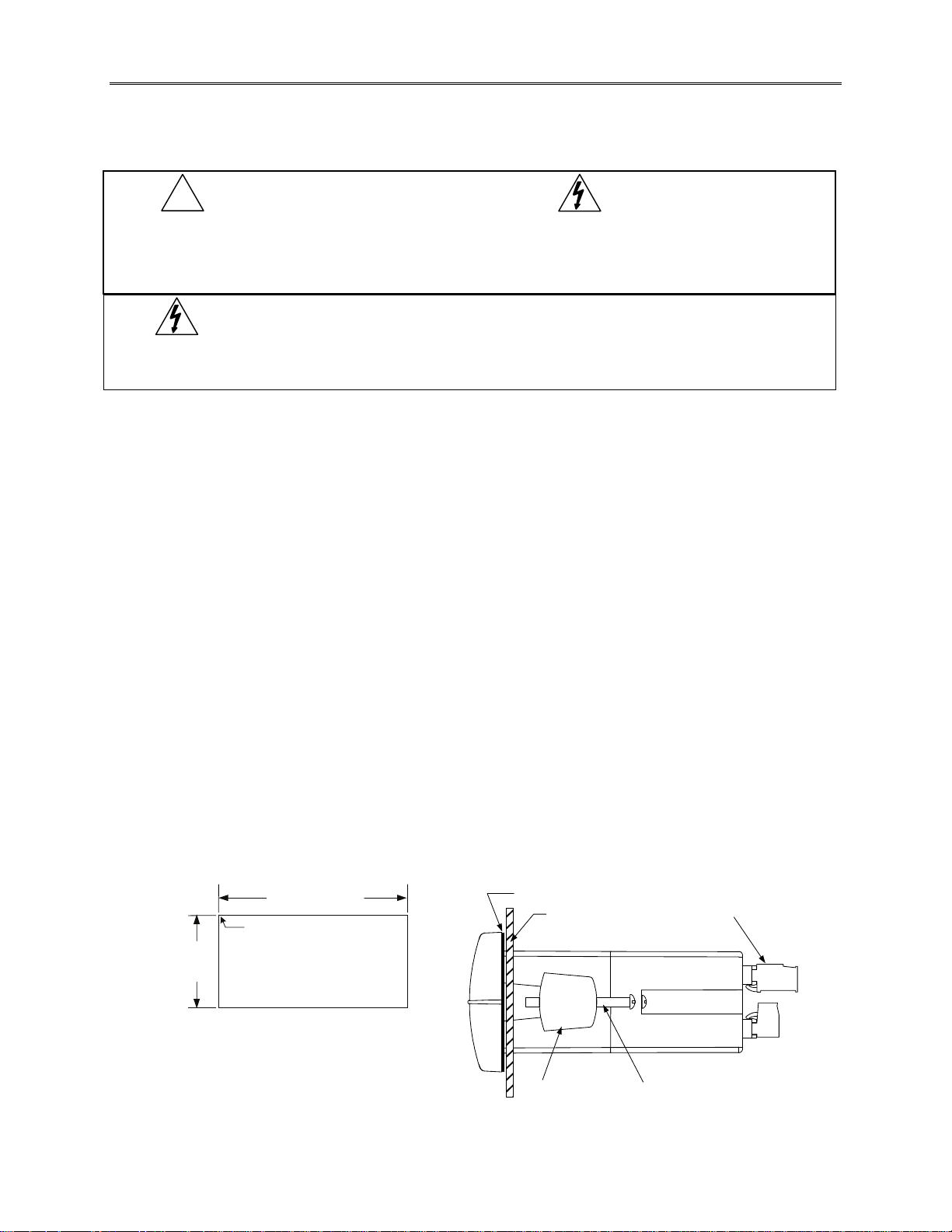
• Prepare a standard 1/8 DIN panel cutout – 3.622" x 1.772" (92 mm x 45 mm). Refer to Figure 1 for
more details.
• Clearance: allow at least 6" (152 mm) behind the panel for wiring.
• Panel thickness: 0.04" - 0.25" (1.0 mm - 6.4 mm).
Recommended minimum panel thickness to maintain Type 4X rating: 0.06" (1.5 mm) steel panel,
0.16" (4.1 mm) plastic panel.
• Remove the two mounting brackets provided with the scanner (back-off the two screws so that there is
¼" (6.4 mm) or less through the bracket. Slide the bracket toward the front of the case and remove).
• Insert scanner into the panel cutout.
• Install mounting brackets and tighten the screws against the panel. To achieve a proper seal, tighten
the mounting bracket screws evenly until scanner is snug to the panel along its short side. DO NOT
OVER TIGHTEN, as the rear of the panel may become damaged.
B
1.772"
(45mm)
3.622" (92 mm)
Square Corners to 0.060"
(1.5mm) Max Radius
Panel Cutout
to DIN 43700
Gasket
Panel
Removable
Connectors
Tolerances:
: +0.032 (+0.8mm)
-0.000 (-0.0mm)
B: +0.024 (+0.6mm)
-0.000 (-0.0mm)
Mounting
Bracket
Mounting
Screw
Figure 1. 1/8 DIN Panel Cutout Dimensions & Panel Mounting Details
16
PD6080/PD6081 Super Snooper Modbus Scanner Instruction Manual
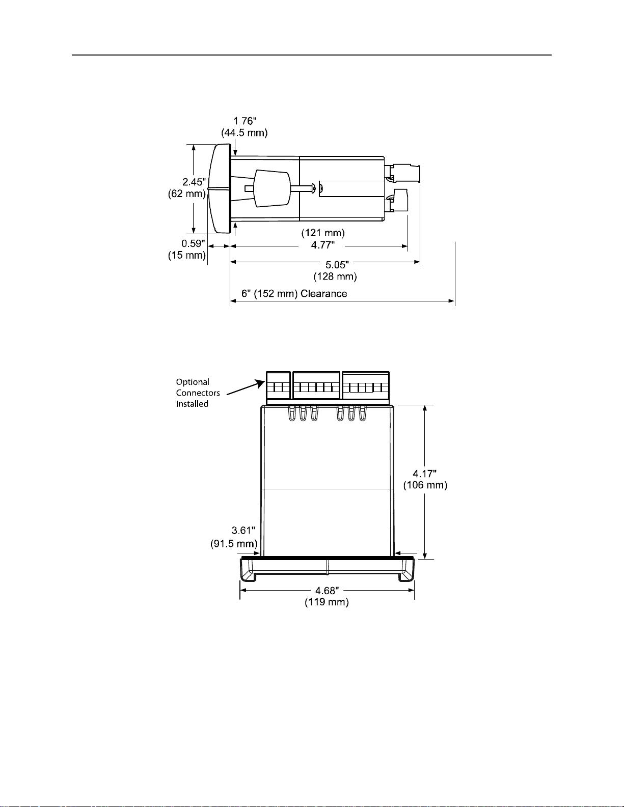
MOUNTING DIMENSIONS
Figure 2. Scanner Dimensions - Side View
N
C
C
+
-
R
O
C
O
N
N
N
C
O
N
C
C
N
O
N
N
C
C
Figure 3. Scanner Dimensions - Top View
17
PD6080/PD6081 Super Snooper Modbus Scanner Instruction Manual
Configuration for 12 or 24 VDC Power Option
Do not exceed voltage rating of the selected configuration.
M-LINK
24 VDC
12 VDC
POWER
J9 CONFIGURATION
MAIN BOARD
12 V
+
_
Figure 4. Jumper Configuration for 12/24 VDC Power
J9
24 V
Factory
Default
Warning!
Scanners equipped with the 12/24 VDC power option are shipped from the factory ready to operate
from 24 VDC.
To configure the scanner for 12 VDC power:
1. Remove all the connectors.
2. Unscrew the back cover.
3. Slide the back cover about 1 inch.
4. Configure the J9 jumper, located behind the power connector, for 12 V as shown below.
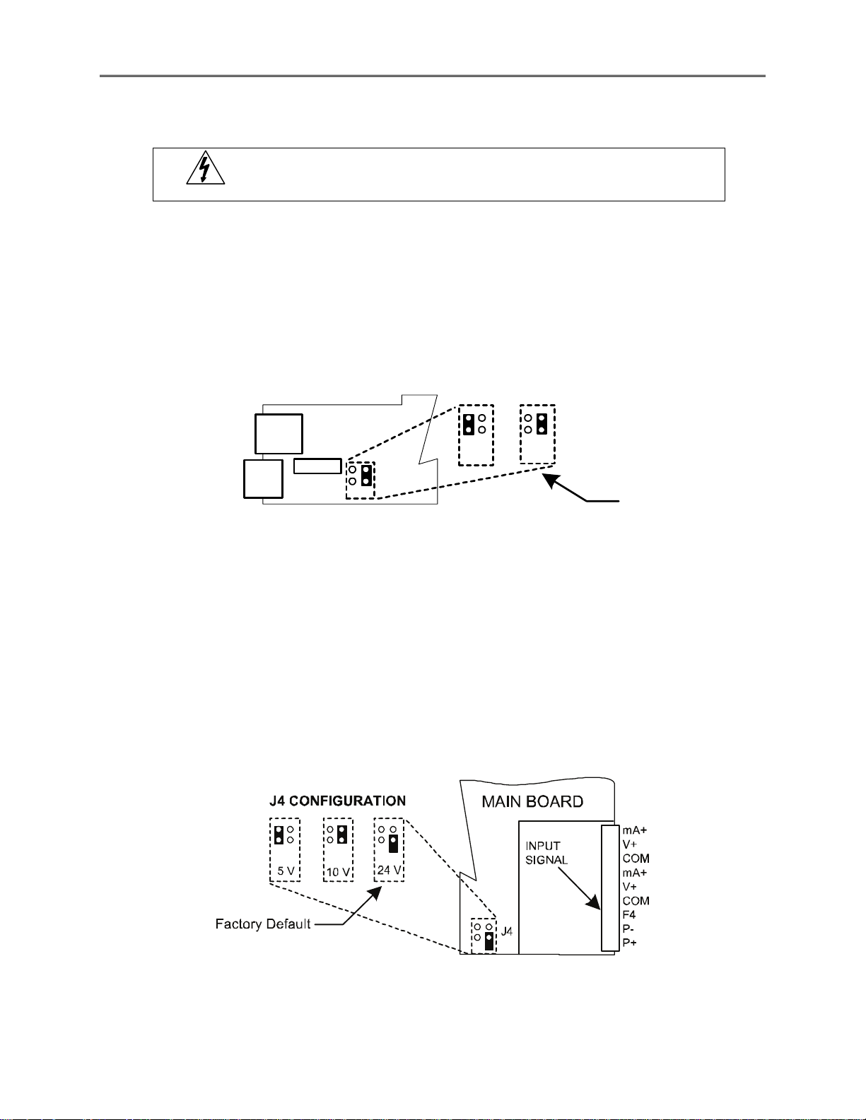
Transmitter Supply Voltage Selection (P+, P-)
All scanners, including models equipped with the 12/24 VDC power option, are shipped from the
factory configured to provide 24 VDC power for the transmitter or sensor. If the transmitter requires 5
or 10 VDC excitation, the internal jumper J4 must be configured accordingly.
To access the voltage selection jumper:
1. Remove all the wiring connectors.
2. Unscrew the back cover.
3. Slide out the back cover by about 1 inch.
4. Configure the J4 jumper, located behind the input signal connector, for the desired excitation
voltage as shown.
Figure 5. Transmitter Supply Voltage Selection
18
PD6080/PD6081 Super Snooper Modbus Scanner Instruction Manual
Connections
All connections are made to removable screw terminal connectors located at the rear of the scanner.
!
Caution!
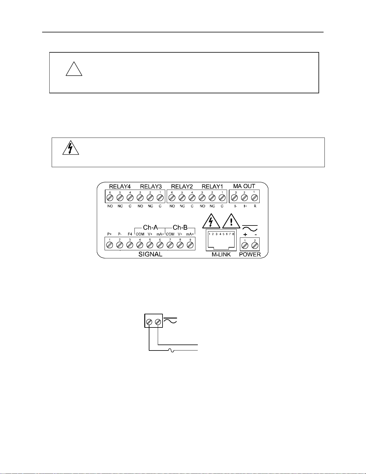
Connectors Labeling
The connectors’ label, affixed to the scanner, shows the location of all connectors available wi th
requested configuration.
Warning!
Use copper wire with 60°C or 60/75°C insulation for all line voltage conne ction s.
Observe all safety regulations. Electrical wiring should be performed in
accordance with all applicable national, state, and local codes to prevent
damage to the scanner and ensure personnel safety.
Do not connect any equipment other than Precision Digital’s expansion
modules, cables, or scanners to the RJ45 M-LINK connector. Otherwise
damage will occur to the equipment and the scanner.
Figure 6. Connector Labeling for Fully Loaded PD6080/6081
Power Connections
Power connections are made to a two-terminal connector labeled POWER on the back of the scanner. The
scanner will operate regardless of DC polarity connection. The + and - symbols are only a suggested wiring
convention.
POWER
-
+
AC or DC
POWER
Required External Fuse:
5 A max, 250 V Slow Blow
Figure 7. Power Connections
19

PD6080/PD6081 Super Snooper Modbus Scanner Instruction Manual
Serial Communications Connection
Serial communications connection is made to an RJ45 connector labeled M-LINK on the back of the
scanner. The Modbus Scanner uses the PDA1485 RS-485 adapter to interface with other Modbus
devices and the PDA8485 RS-485 to USB converter or PDA7485 RS-232 to RS-485 converter to connect
to a PC. The same port is used for interfacing with all expansion modules (e.g. external relays, digital I/O).
Use the PDA1200 meter copy cable for scanner-to-scanner interfacing for cloning purposes (i.e. copying
settings from one scanner to other scanners).
Figure 8. Serial Communications Connections
20
PD6080/PD6081 Super Snooper Modbus Scanner Instruction Manual
Serial Communications Connections Table
The table below shows the terminal connections for 3-wire RS-485 devices.
PD6080/6081
Master
PDA1485
RS-485 Adapter
DODI
DODI
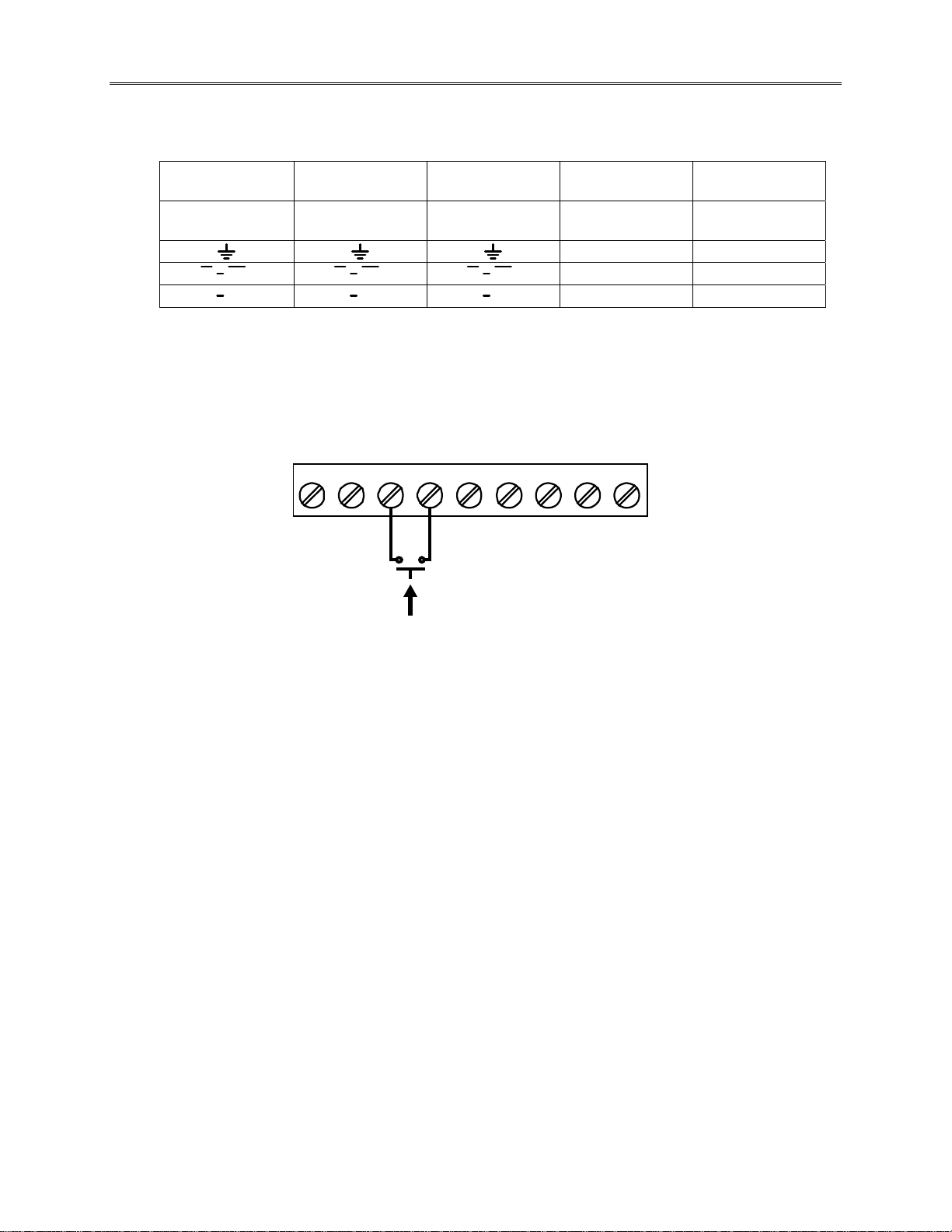
F4 Digital Input Connections
A digital input, F4, is standard on the scanner. This digital input connected with a normally open closure
across F4 and COM, or with an active low signal applied to F4.
PD6080/6081
Snooper
PDA1485
RS-485 Adapter
DODI DODI
DODI DODI
P- F4P+ COM V+
3412 5
PC
Connection
PDA8485
RS-485 to USB
mA+ COM V+ mA+
Modbus
Slave Meter
RS-485 RS-485
G GND
D- A (-)
D+ B (+)
7869
Modbus
Level Gauge
Ack
Figure 9. F4 Digital Input Connections
21
PD6080/PD6081 Super Snooper Modbus Scanner Instruction Manual
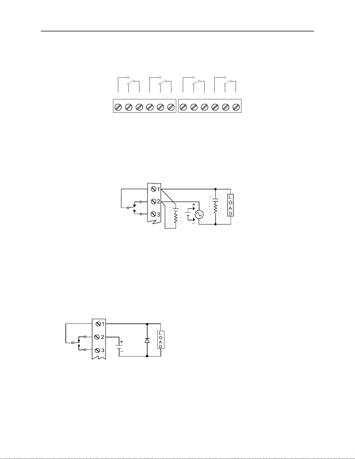
Relay Connections
Relay connections are made to two six-terminal connectors labeled RELAY1 – RELAY4 on the back of
the scanner. Each relay’s C terminal is common only to the normally open (NO) and normally closed (NC)
contacts of the corresponding relay. The relays’ C terminals should not be confused with the COM
(common) terminal of the INPUT SIGNAL connector.
RELAY4 RELAY3
4365 21
CNONO NC NC C
RELA Y2 RELAY1
4365 21
CNONO NC NC C
Figure 10. Relay Connections
Switching Inductive Loads
The use of suppressors (snubbers) is strongly recommended when switching inductive loads to prevent
disrupting the microprocessor’s operation. The suppressors also prolong the life of the relay contacts.
Suppression can be obtained with resistor-capacitor (RC) networks assembled by the user or purchased
as complete assemblies. Refer to the following circuits for RC network assembly and installation:
C
C
R
Figure 11. AC and DC Loads Protection
Choose R and C as follows:
R: 0.5 to 1 Ω for each volt across the contacts
C: 0.5 to 1 µF for each amp through closed contacts
Notes:
1. Use capacitors rated for 250 VAC.
2. RC networks may affect load release time of solenoid loads. Check to confirm proper operation.
3. Install the RC network at the scanner's relay screw terminals. An RC network may also be installed
across the load. Experiment for best results.
R
Use a diode with a reverse
breakdown voltage two to three
times the circuit voltage and
forward current at least as large
as the load current.
Figure 12. Low Voltage DC Loads Protection
RC Networks Available from Precision Digital
RC networks are available from Precision Digital and should be applied to each relay contact switching an
inductive load. Part number: PDX6901.
Note: Relays are de-rated to 1/14 HP (50 watts) with an inductive load.
22
PD6080/PD6081 Super Snooper Modbus Scanner Instruction Manual
4-20 mA Output Connections
Connections for the 4-20 mA transmitter output are made to the connector terminals labeled MA OUT.
The 4-20 mA output may be powered internally or from an external power supply.
24 V
24 V
RELAY1
MA OUT
321
+
4-20 mA Input
Remote Dis play,
Chart Recorder, Etc.
RI- I+
132
-
RELAY1
321
+
4-20 mA
Input Meter
-
MA OUT
-
+
12-35 VDC
Power
Supply
RI- I+
132
Figure 13. 4-20 mA Output Connections
Analog Output Transmitter Power Supply
The internal 24 VDC power supply powering the analog output may be used to power other devices, if the
analog output is not used. The I+ terminal is the +24 V and the R terminal is the return.
External Relay, Analog Output, & Digital I/O Connections
The relay, analog out, and digital I/O expansion modules PDA1004, PDA1011, and PDA1044 are
connected to the scanner using a CAT5 cable provided with each module. The two RJ45 connectors on
the I/O expansion modules are identical and interchangeable; they are used to connect additional
modules to the system. See LIM1044, Expansion Module Instruction Manual, for details.
Note: The jumper located between the RJ45 connectors of the PDA1044 must be removed on the second
digital I/O module in order for the system to recognize it as module #2.
Do not connect or disconnect the expansion modules with the power on!
Warning!
More detailed instructions are provided with each optional expansion
module.
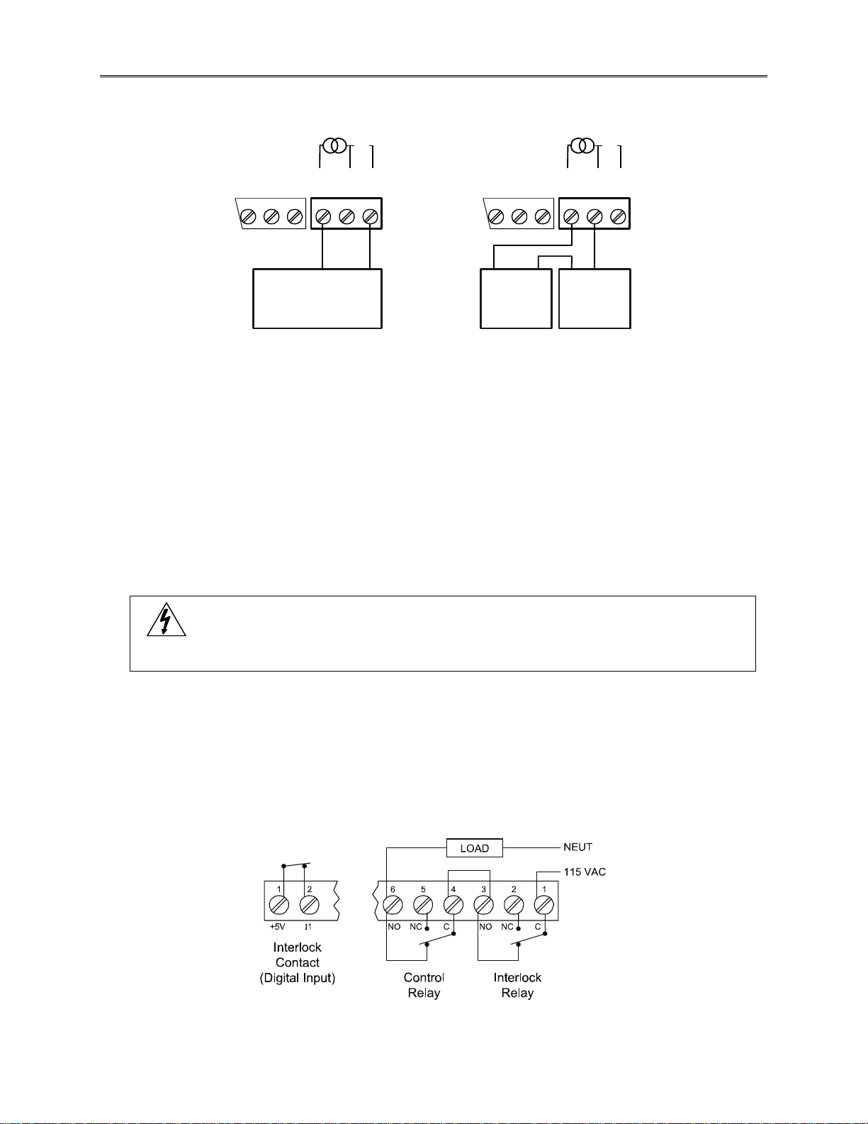
Interlock Relay Feature
As the name implies, the interlock relay feature reassigns one, or more, alarm/control relays for use as
interlock relay(s). Interlock contact(s) are wired to digital input(s) and trigger the interlock relay. This
feature is enabled by configuring the relay and relative digital input(s). In one example, dry interlock
contacts are connected in series to one digital input which will be used to force on (energize) the
assigned interlock power relay when all interlock contacts are closed (safe). The interlock relay front
panel LED flashes when locked out. The interlock relay would be wired in-series with the load (N/O
contact). See below.
Figure 14. Interlock Connections
23
PD6080/PD6081 Super Snooper Modbus Scanner Instruction Manual
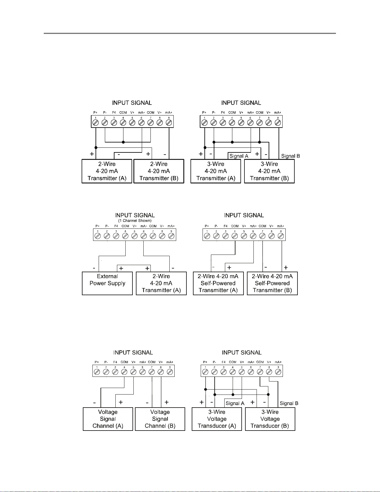
Analog Input Signal Connections
Analog input signal connections are made to a nine-terminal connector labeled SIGNAL on the back of
the scanner. The COM (common) terminals are the return for the 4-20 mA and the ±10 V input signals.
The two COM terminals connect to the same common return, and are not isolated.
Current and Voltage Connections
The following figures show examples of current and voltage connections. There are no switches or jumpers
to set up for current and voltage inputs. Setup and programming is performed through the front panel
buttons.
Figure 15. Transmitters Powered by Internal Supply
Figure 16. Transmitter Powered by Ext. Supply or Self-Powered
The current input is protected against current overload by a resettable fuse. The display may or may not
show a fault condition depending on the nature of the overload. The fuse limits the current to a safe level
when it detects a fault condition, and automatically resets itself when the fault condition is removed.
Figure 17. Voltage Input Connections
The scanner is capable of accepting any voltage from -10 VDC to +10 VDC.
24
PD6080/PD6081 Super Snooper Modbus Scanner Instruction Manual
SETUP AND PROGRAMMING
The analog inputs of the scanner are factory calibrated prior to shipment to read in milliamps and volts,
depending on the input selection. The calibration equipment is certified to NIST standards.
Overview
There are no jumpers involved in the scanner setup procedure.
Setup and programming is done using ScanView software or through the front panel buttons.
After power and signal connections have been completed and verified, apply power to the scanner.
Front Panel Buttons and Status LED Indicators
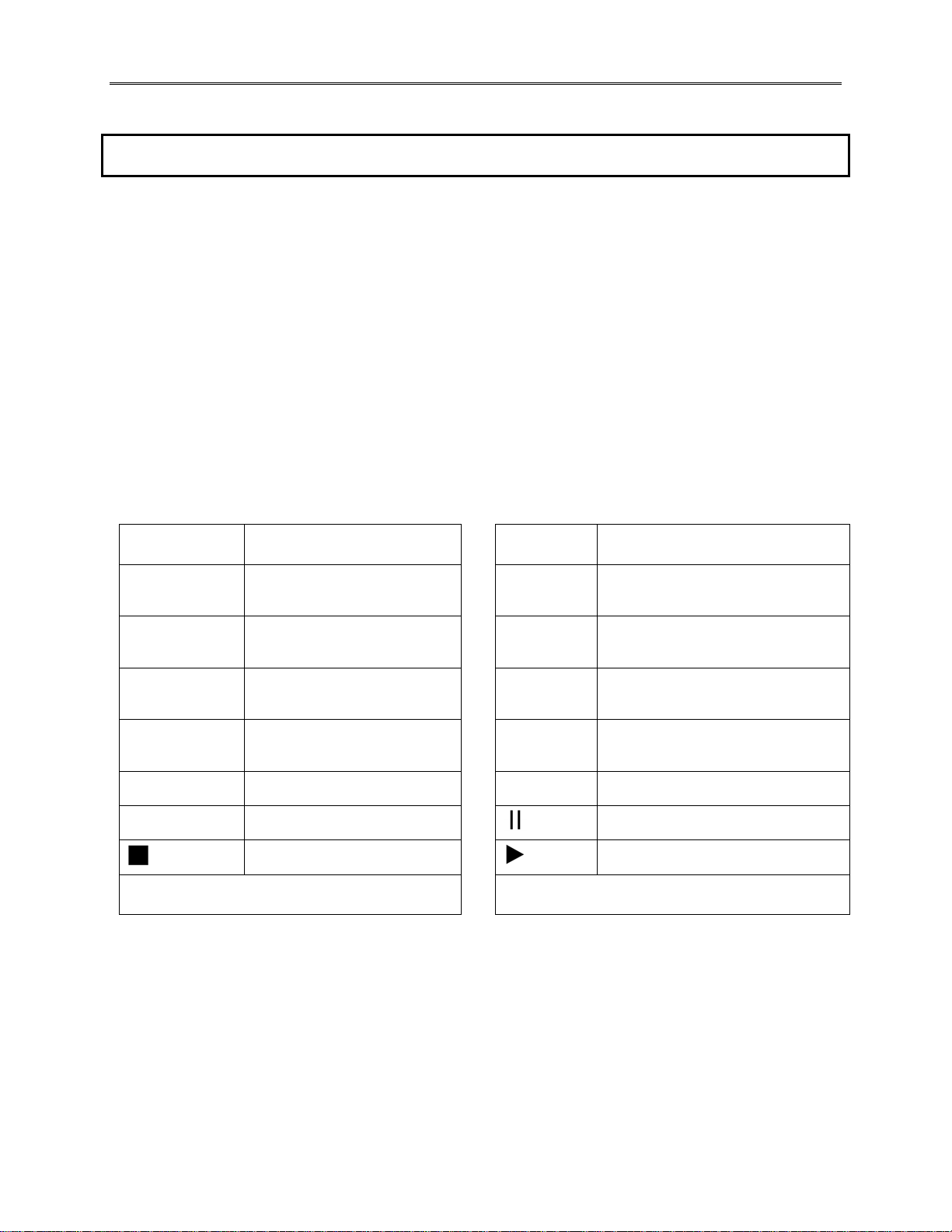
PD6080 PD6081
Button
Symbol/LED
Description LED Status
Menu 1-8 Alarm 1-8 indicator
PREV/Right arrow/F1
NEXT/Up arrow/F2
SCAN/Enter/F3 1-4
PREV
NEXT
STOP
Notes: F4 is a digital input. Alarms 5-8 are
enabled when relay expansion module installed.
• Press the Menu button to enter or exit the Programming Mode at any time.
• Press the Right arrow button to move to the next digit during digit or decimal point programming.
• Press the Up arrow button to scroll through the menus, decimal point, or to increment a digit.
• Press the Enter button to access a menu or to accept a setting.
• Press and hold the Menu button for three seconds to access the advanced f eatures of the scanner.
• Press the SCAN/Enter button once to pause scanning (Pause LED flashes), then press the
SCAN/Enter button again to resume scanning (Play LED turns on).
• Press NEXT to go to the next PV; auto scan resumes after 10 seconds of inactivity.
• Press PREV to go to the previous PV; auto scan resumes after 10 seconds of inactivity.
Go to previous PV
Go to next PV
Stop scan on alarm
1-8
M
/8
/16
F
PAUSE
PLAY
Note: LEDs for relays in manual mode flash with
the “M” LED every 10 seconds.
Flashing: Relay in manual control
mode
th
Displays PV to nearest 1/8
th
of an inch
1/16
Flashing: Relay interlock switch
open
Communications Fault Condition
Press SCAN to pause scanning
Press SCAN to resume scanning
or
25

PD6080/PD6081 Super Snooper Modbus Scanner Instruction Manual
Display Functions & Messages
The following table shows the main menu functions and messages in the order they appear in the menu.
Display Parameter Action/Setting Description
mode
master
Pv.nbr
Pv 1
enable
disabl
Slav.Id
FunCod
Reg.nbr
data
float
short
long
binary
bcd
signed
unsigd
1234
4321
2413
3412
t-poll
t-resp
snooper
Pv.nbr
Pv 1
enable
disabl
Slav.Id
FunCod
Fun 03
Fun 04
Fun 65
Reg.nbr
5 dig
6 dig
data
Mode
Master
PV Number
PV
Enable
Disable
Slave ID
Function Code
Register Number
Data Type
Floating Point Data Type
Short Integer Data Type
Long Integer Data Type
Binary
BCD
Signed
Unsigned
Byte Order
Byte Order
Byte Order
Byte Order
Polling Time
Response Time
Snooper
PV Number
PV
Enable
Disable
Slave ID
Function Code
Function Code 03
Function Code 04
Function Code 65
Register Number
Register Number Digits
Data Type
Enter Mode menu
Enter Master Mode
Select PV
Select PV 1-16
Enable PV
Disable PV
Enter the unique Slave ID for each PV
Enter the Function Code for each PV
Enter the Register Number for each PV
Enter the Data Type for each PV
Floating Point Data Type. Select Floating Point as the data type to be
read from the slave device.
Short Integer Data Type. Select Short Integer as the data type to be
read from the slave device.
Long Integer Data Type. Select Long Integer as the data type to be
read from the slave device.
Binary Data format. Select Binary format for Short or Long integers.
BCD Data format. Select BCD format for Short or Long integers.
Signed Data. Select Signed Binary format for Short or Long integers.
Unsigned Data. Select Unsigned Binary format for Short or Long
integers.
Select big-endian byte order.
Select little-endian byte order.
Select byte-swapped big-endian byte order. Not available for Short
integer.
Select byte-swapped little-endian byte order. Not available for Short
integer.
Enter Polling Time (the time between read commands). In other words,
how often the display is updated in Master mode.
Enter the time allowed for a slave device to respond to a command.
Enter Snooper Mode
Select PV
Select PV 1-16
Enable PV
Disable PV
Enter the unique Slave ID of the device to be polled by Master
Enter the Function Code for each PV
Use Function Code 03 to read slave device
Use Function Code 04 to read slave device
Use Function Code 65 to read slave device
Enter the Register Number for each PV
Select either 5 (x0001-x9999) or 6 (x00001-x65536) digits for the
Register Number by pressing the Right Arrow in Register Number
menu.
Enter the Data Type for each PV
26

PD6080/PD6081 Super Snooper Modbus Scanner Instruction Manual
Display Parameter Action/Setting Description
float
short
long
binary
bcd
signed
unsigd
1234
4321
2413
3412
t-resp
slave
data
float
short
long
binary
bcd
signed
unsigd
1234
4321
2413
3412
t-resp
setup
pv
Pv 1
tag
units
formt
dec
Ft In 8
Ft In 16
Dec.Pt
Disp.dp
Floating Point Data Type
Short Integer Data Type
Long Integer Data Type
Binary
BCD
Signed
Unsigned
Byte Order
Byte Order
Byte Order
Byte Order
Response Time
Slave
Data Type
Floating Point Data Type
Short Integer Data Type
Long Integer Data Type
Binary
BCD
Signed
Unsigned
Byte Order
Byte Order
Byte Order
Byte Order
Response Time
Setup
Process Variable
PV
Tag
Units
Format
Decimal
Eighths
Sixteenths
Decimal Point
Display Decimal Point
Floating Point Data Type. Select Floating Point as the data type to be
read from the slave device.
Short Integer Data Type. Select Short Integer as the data type to be
read from the slave device.
Long Integer Data Type. Select Long Integer as the data type to be
read from the slave device.
Binary Data. Select Binary format for Short or Long integers.
BCD Data. Select BCD format for Short or Long integers.
Signed Data. Select Signed Binary format for Short or Long integers.
Unsigned Data. Select Unsigned Binary format for Short or Long
integers.
Select big-endian byte order.
Select little-endian byte order.
Select byte-swapped big-endian byte order. Not available for Short.
Select byte-swapped little-endian byte order. Not available for Short.
Enter the time allowed for a slave device to respond to a command.
Enter Slave Mode
Enter the Data Type for each PV
Floating Point Data Type. Select Floating Point as the data type to be
read from the slave device.
Short Integer Data Type. Select Short Integer as the data type to be
read from the slave device.
Long Integer Data Type. Select Long Integer as the data type to be
read from the slave device.
Binary Data. Select Binary format for Short or Long integers.
BCD Data. Select BCD format for Short or Long integers.
Signed Data. Select Signed Binary format for Short or Long integers.
Unsigned Data. Select Unsigned Binary format for Short or Long
integers.
Select big-endian byte order.
Select little-endian byte order.
Select byte-swapped big-endian byte order. Not available for Short
integer.
Select byte-swapped little-endian byte order. Not available for Short
integer.
Enter the time allowed for a slave device to respond to a command.
Enter Setup menu
Enter PV Setup menu
Select PV 1-16
Tag
Units
Format (Decimal, Eighths, or Sixteenths of an Inch)
Decimal Format
Eighth Inch Format
Sixteenth Inch Format
Decimal Point menu
Set the decimal point position for the display. This is independent from
float decimal point.
27

PD6080/PD6081 Super Snooper Modbus Scanner Instruction Manual
Display Parameter Action/Setting Description
flot.dp
SCale
Inp 1
Dis 1
Inp 2
Dis 2
dsplay
top
D pv
D Ch-C
Pv.unit
Tg.pvn
Tg.pvn.u
C.unit
Tg. C. u
Dset 1
Hi-pv
Lo-pv
Hi-C
Lo-C
botom
D tag
D tag.u
D off
d-Inty
relay
assign
Relay 1
Pv 1
m-pv
Rly 1
act 1
Auto
A-nman
LatCH
Lt-CLr
Altern
SAmpl
Off
FaiLSF
FLS 1
on
off
DeLAY
Floating Decimal Point
Scale PV
Input 1
Display 1
Input 2
Display 2
Display
Top Display
Display PV
Display C Channel
Display PV & Units
Display Tag, PV Number
Display Tag, PV# & Units
Display C & Units
Display Tag, C, & Units
Display Set Points 1-8
Display Max PV 1-16
Display Min PV 1-16
Display Max Ch C1-C4
Display Min Ch C1-C4
Bottom Display
Display Tag
Display Tag & Units
Display off
Display Intensity
Relay Setup
Assign Relay
Relay 1-8
PV 1-16
Multiple PVs
Relay 1-8
Relay Action 1-8
Automatic
Auto-manual
Latching
Latching-cleared
Alternate
Sample
Off
Fail-safe
Fail-safe 1
On
Off
Delay
Floating Decimal Point. Select the decimal point for the expected
floating point data.
Scale PV
Calibrate input 1 signal or program input 1 value
Program display 1 value
Calibrate input 2 signal or program input 2 value (up to 32 points)
Program display 2 value (up to 32 points)
Enter Display Setup menu
Top Display
Display PVs 1-16
Display Math Channels C1-C4
Display PV & Units
Display Tag & PV Number selected
Display Tag, PV Number selected, & Units
Display C1-C4 & Units
Display Tag, C1-C4 & Units
Display Set Points 1-8
Display Maximum value for each enabled PV1-16
Display Minimum value for each enabled PV1-16
Display Maximum for math channels C1-C4
Display Minimum for math channels C1-C4
Bottom Display
Display Tag
Display Tag & Units
Display Off
Display Intensity
Enter Relay Setup menu
Assign Relay menu
Assign Relay 1-8
Map Relay to PV 1-16
Map Relay to Multiple PVs
Relay 1-8
Assign Relay Action for relays 1-8
Set relay for automatic reset
Set relay for auto or manual reset any time
Set relay for latching operation
Set relay for latching operation with manual reset only after alarm
condition has cleared
Set relay for pump alternation control
Set relay for sample time trigger control
Turn relay off
Enter Fail-safe menu
Set relay 1-8 fail-safe operation
Enable fail-safe operation
Disable fail-safe operation
Enter relay Time Delay menu
28

PD6080/PD6081 Super Snooper Modbus Scanner Instruction Manual
Display Parameter Action/Setting Description
DLY 1*
On 1
OFF 1
break
No act
On
Off
Aout
AOut 1*
Dis 1
Out 1
Dis 2
Out 2
serial
SCan.ID
baud
Tr dly
parity
t-byt
pass
Pass 1
Pass 2
Pass 3
unloc
locd
999999
-99999
Delay 1*
On 1
Off 1
Break
No action
On
Off
Analog output
Aout channel
Display 1
Output 1
Display 2
Output 2
Serial
Scan ID
Baud Rate
Transmit Delay
Parity
Byte-to-byte Timeout
Password
Password 1
Password 2
Password 3
Unlocked
Locked
Flashing
*Enter relay 1-8 time delay setup
Set relay 1 On time delay
Set relay 1 Off time delay
Set relay condition if communication break detected
Ignore break condition. No change in relay state when
Communications Break detected.
Relay goes to alarm condition when break detected. Relay turns on
when Communications Break detected.
Relay goes to non-alarm condition when break detected. Relay turns
off when Communications Break detected.
Enter the Analog Output scaling menu
Analog Output source channel (*1-3)
Program the first Display value for the Analog Output.
Program the first Output value that corresponds to the Display 1 value
for the Analog Output. (e.g. 4.000 mA).
Program the second Display value for the Analog Output.
Program the second Output value that corresponds to the Display 2
value for the Analog Output. (e.g. 4.000 mA). (e.g. 20.000 mA)
Enter Serial menu
Enter Scan ID of the meter being polled (1-247)
Select Baud Rate (Choices: 300/600/1200/2400/4800/9600/19,200)
(Must match that of other devices)
Enter Transmit Delay
(Master’s delay must be greater than Snooper or slave devices)
Select Parity (Even, Odd, None 1-Stop, or None 2-Stop)
(Must match that of other devices)
Enter the timeout value allowed between received bytes.
(This is used to fix communication problems with slow devices).
Enter the Password menu
Set or enter Password 1
Set or enter Password 2
Set or enter Password 3
Program password to lock scanner
Enter password to unlock scanner
Over/under range condition
29
PD6080/PD6081 Super Snooper Modbus Scanner Instruction Manual
ScanView Software
Free ScanView software allows a Super Snooper Modbus Scanner to be accessed with a computer.
Configure multiple scanners, conveniently monitor critical information, and Datalog right from a PC with
ease. Available for download at www.predig.com
.
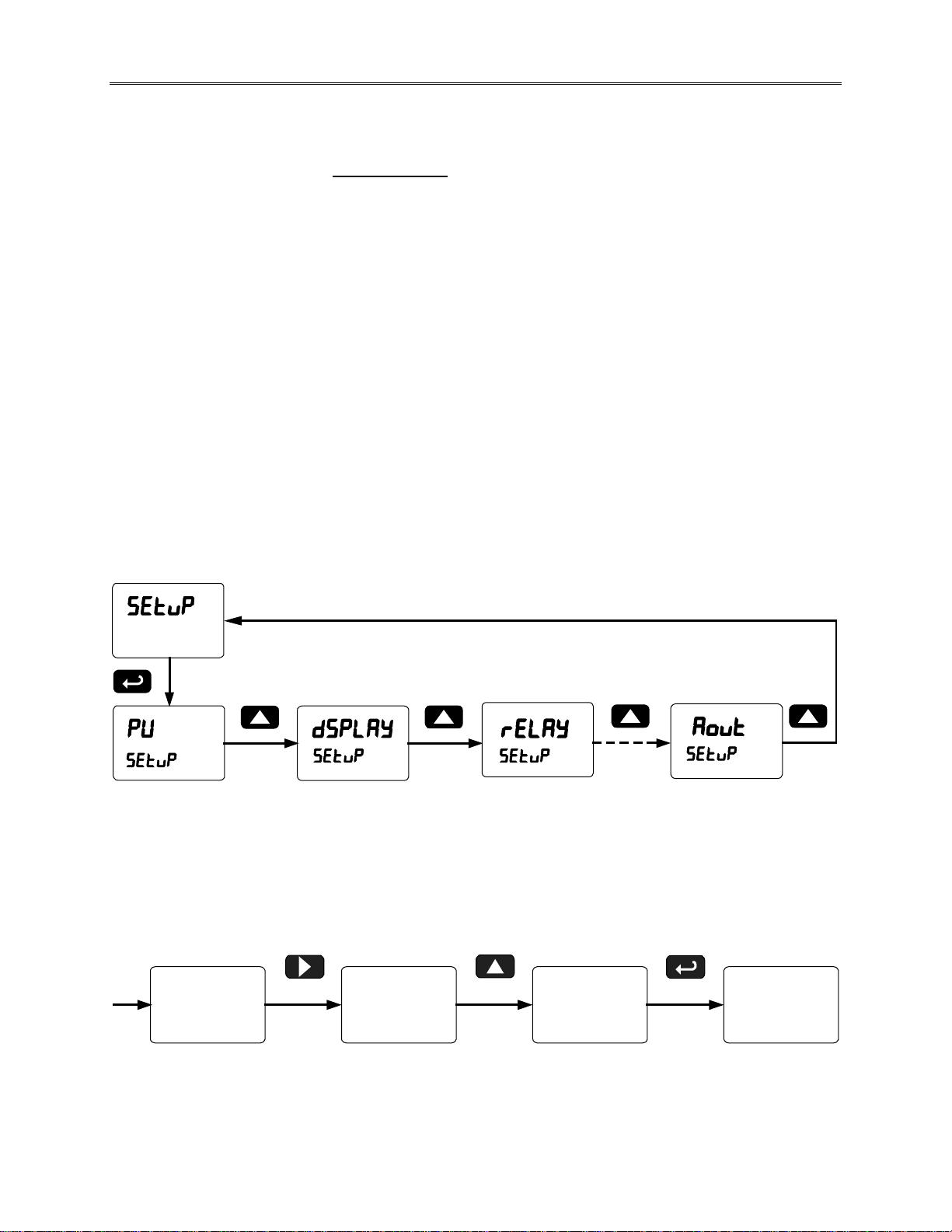
Menu Navigation Tip
• The Up arrow scrolls through the sub-menus within a menu, after the last item it returns to the top
menu. Press Enter to step into the menu again or press Up arrow to move to the next menu.
Note: There are some exceptions (e.g. PV - Enable - - Data type ▲ Next PV).
• Press Menu to exit programming at any time.
Setting Numeric Values
The numeric values are set using the Right and Up arrow buttons. Press the Right arrow to select the
next digit and the Up arrow to increment the digit’s value. The digit being changed is displayed brighter
than the rest. Press and hold the Up arrow to auto-increment the display value. Press the Enter button, at
any time, to accept a setting or the Menu button to exit without saving changes.
004.000
dis 1 dis 1 dis 1
Select
Next
Digit
004.000
Increment
Digital
Value
30
005.000
Accept
Setting
Next
Setting
 Loading...