

Page 1

DIGITAL CONTROLLER
®
NOVA PD540 Series
Instruction Manual
PD540 - PD549
PRECISION DIGITAL CORPORATION
89 October Hill Road z Holliston MA 01746 USA
Tel (800) 343-1001
z
Fax (508) 655-8990
Page 2

PD540 Series Nova Digital Process and Temperature Controller Instruction Manual
Disclaimer
The information contai ned i n t h i s docu m ent i s su b j ec t t o c h ang e wi t hou t n oti ce.
Precision D i g i t al C or p or ati on m akes no repr esentati ons or warranties with
res p ect t o t he c on t en ts h ereof , an d s p ecifically disclai m s any i m p l ied warran tie s
of merchantability or fitness f or a particular purpose.
Registered Trademarks
MODBUS® is a registered tr ademar k of Sch n eid er A u t omati on I n c. A l l ot h er
trademarks men t ion ed i n t hi s doc u men t ar e t h e pr op ert y of their respective
owner s.
Nova PD540 Series Model Number Guide
Digital Control l er
Size - DIN Cutou t
0, 1 = 1/16 D I N
2, 3 = 1/8 DIN ( H)
4, 5 = 3/16 D I N
6, 7 = 1/8 DIN (V)
8, 9 = 1/4 D I N
Power
6 = 100-240 VAC
Display
R = Red LED
Main Control Ou tp u t
PD540, PD541, PD544, PD545:
A = 1 relay & 1 analog output
PD542, PD543, PD546 to PD549:
B = 1 relay & 2 analog outputs
Visit our Web S i te
http://www.predig.com
0-6RA-00PD5 4
Notes:
0, 2, 4, 6, 8 = Heating or Cooling
1, 3, 5, 7, 9 = Heating & Cooling
Options
00 = None
PD540, PD541
11 = 1 relay & 2 digital inputs
14 = 1 relay & RS-485
31 = 1 analog output & digital input s
34 = 1 analog output & RS-485
PD544, PD545:
04 = RS-485
51 = 2 relays, 1 analog output
& 2 digital inputs
54 = 2 relays, 1 analog output
& RS-485
PD542, PD543:, PD546 to PD 549:
21 = 2 relays & 2 digital inputs
24 = 2 relays & RS-48 5
©2009 Precision Digital Corpor ati on. All r i g ht s res er ved.
2
Page 3

PD540 Series Nova Digital Process and Temperature Controller Instruction Manual
Table of Contents
1. Safety Guide and Specifications
1.1 Specifications
2. Front Panel Buttons and LED Indicators
3. Parameter Map
4. Operation Flow Chart
5. Controller Parame t er Se t up
5.1 Input Group (G.IN) 15
5.2 Output Group (G.OUT ) 19
5.3 Control Group (G.CT L ) 22
5.4 SP Group (G. SP) 25
5.5 PID Group (G.PI D )
5.6 Auto-Tuning Group (G.AT) 31
5.7 Alarm Group (G.ALM)
5.8 Retransmission Group (G.RET )
5.9 Communication Group (G.COM)
6. Error Display and Correction
7. Installation
7.1 D imensions and Panel Cutouts
7.2 Panel Mounting
7.3 Power Cable Specifications
7.4 Terminal Specifications
7.5 Terminal Assignment, Connections, and Ratings
5
7
11
12
14
15
27
33
36
37
39
40
40
45
46
46
47
3
Page 4

PD540 Series Nova Digital Process and Temperature Controller Instruction Manual
7.6 Grounding and Power Cable Connection 52
7.7 Signal Input Connection
52
7.8 Analog Output Connection 53
7.9 Relay Output Connection (RELAY) 54
7.10 Digital Input Connection (DI) 54
7.11 Use of an External Relay 54
7.12 Communication Wiring (RS-485) 55
Appendix
Table of D-Registers 56
Tables and Figures
Table 1: Universal Input Selection 15
Table 2: DI Operation 22
Table 3: Alarm Selection 34
Fig 1: Temperature Bi as 17
Fig 2: Bias Formula Calculation 17
Fig 3: Time-Proportional PID Control Output 20
Fig 4: Output Delay and Timer Functi ons 22
Fig 5: Overshoot Suppression with Fuzzy Logic 27
Fig 6: Heating and Cooling Outputs Using PID Control 29
Fig 7: Heating On/Off and Cooling PID Outputs 29
Fig 8: Heating PID and Cooling On/Off Outputs 30
Fig 9: Auto-Tuning 31
Fig 10: Auto-Tuning Gain 32
Fig 11: Alarm Oper at i on 34
4
Page 5

PD540 Series Nova Digital Process and Temperature Controller Instruction Manual
1. Safety Guide and Specifications
!
CAUTION
?
NOTE
&
!
CAUTION
!
CAUTION
The following safety symbols are used in this manual
(1) This symbol notifies the use r o f s pe c i f ic in f o rmatio n r e l a t in g t o t h e sa f e oper ation of the controller.
Information noted with this symbol must be observed to protect the user from injury and to prevent damag e
to the product.
(A) For User: Be awa re of t h i s ma rking i n t h e manual and refer to the explanation in the manual to
(2) For Installer : Stud y the warning s marked t o p r e vent inju ry and dama g e .
(2) Functional ea rth te rminal : This symbol i n d ic a t e s t h a t t h e t e r mi n a l mu st b e c onnected to ground.
(3) This symbol i ndicates additional information on the features of the product.
(4) This symbol directs the reader to further information on the current topic.
Precautions R eg a rd i ng This Instr ucti o n Ma n ua l
(1) This manual must be kept in the possession of the end user and in a suitable place for the operator to
study and to check the functions of the product.
(2)The installer and oper ator should carefully study and understand how to operate this product before use.
(3)This manual describes the functions of the product. Precision Digital Corporation does not guarantee
that the functions will suit a particu lar pu r pose .
(4) The contents of this manual have been reviewed for accuracy and correctness. However, shou l d a n y
errors or omission s c o me t o t h e at t e n t i o n o f t h e u se r, con t a ct t e c h n ic a l s u pport as listed on the back of this
manual
Safety Procedures and Unauthorized Modification Warning
(1)In order to prote c t t h is p r oduct and the system controlled by it against damage and ensure its safe use,
make certain t h a t a ll o f t h e sa f e t y instructi o n s and pr ecautions in this manual are strictly adhered to.
(2)Precision Digital Corporation does not guarantee safety if the products are not handled in accordance
with this instruction manual.
(3) If separate prot ec t i o n o r safe t y circ u it s a r e t o b e in s t a ll e d in t h e s y s t e m wh ic h is co n t rolle d b y t h i s p r oduct,
ensure that such circu i t s a re ins t a ll e d e xternal t o t h is p r o d u ct .
(4) Do not make modifications or additions internally to the product. It may cause personal injur y to t h e u se r or
damage to the product.
(5)Contact tech n ic a l s upport as listed on the back of the manual for warranty and repair issues.
(6)Exposure to e xcessive mo i st u re, el e ct rical o verloads, or mechanical vibration may damage the product.
prevent injury and damage.
!
CAUTION
Limited Liability
Precision Digital Corpo ration a s su me s n o li a b ility t o an y pa rt y fo r any lo ss or d amage, dir ect or in dir ect ,
caused by the use of or any unpredictable defect of the product.
5
Page 6

PD540 Series Nova Digital Process and Temperature Controller Instruction Manual
Operational Enviro nment Precautions
!
CAUTION
CAUTION
(1)Only operate the c o nt rolle r when it is properly installed.
(2)When inst alling the controller, select a location where:
Rear terminals a re pr o t e ct e d f r o m a c ci d e n t a l c o n t a ct .
Mechanica l vibrati o n s a re minima l .
No corrosive ga s i s p resen t .
Temperature fluctuation is minimal.
Temperat u r e c a n b e mai n t a in e d between 1 0 and 50 ºC (50 and 110ºF) with 20 to 90% RH.
No direct heat r adiation is present.
High levels of electr oma g n e t i c i n t e r f e r e n c e a r e n o t p r e s e n t
The unit is not exposed to water.
No flammable materials are present.
Dust particles ar e n o t p r e s e n t in t h e a i r .
Expo s u r e t o u l t r a violet r a y s is min i mal .
Openings on t h e r e a r of th e c o n t r o l le r are n o t b lo c ke d .
(3)This unit is suitable fo r inst a ll a t io n i n a n e n viornment c l as s if i e d a s Pollution D e g r e e 2 .
(4)This unit is designated as Installation Category I I .
(5) If the equipment is used in a manner not specified by the manufacturer, the protection provided by
the equipment may be impair e d .
(6)A switch or circuit -bre a ke r acti n g a s t h e d i sc onnect dev ice shall be included in the application or the
installation.
Contr olle r Mounting Pr ecaut ions
!
Keep the input circuit wiring as far a s poss i bl e awa y from po wer a nd ground circuits.
Keep the u n i t s i n 1 0 t o 5 0 º C ( 5 0 t o 110º F) with 20% to 90% re l a t ive humidit y (RH ).
The controller may need a warm up period to return to operating temperature ranges when below 10ºC.
To prevent electric sho c k, b e s u r e t o t u r n o f f t h e p o we r sour c e and circuit breaker before wiring.
The po we r requi r e me n t s a r e 1 0 0 t o 2 40 V A C , 5 0 / 6 0 H z , 1 0 V A max. Do not s wit c h p owe r
supplies without first disconnecting the power supply.
F ollow the operating procedures and precautions in the manual to avoid fire, shock, damage to the unit,
or injury. Follow the operations and mounting directions indicated in this manual.
Always create a ground connection where indicated, however do not ground to gas pipes,
water pipes, lighten i n g r o d s, o r oth er pot e n t ia l ly haz a r dous metal objects.
Do not apply power to the unit until all connections have been made.
Do not cov e r t h e venting h o le s in t h e r e a r of t h e u n i t .
6
Page 7

PD540 Series Nova Digital Process and Temperature Controller Instruction Manual
1.1 SPECIFICATIONS
Except where note d a ll sp e c i f ic a t io n s apply to operation at 23ºC.
General
DISPLAY Dual 4 digits, red LED, -1999 to 9999
FRONT PANEL 1/16 & 1/8 DIN: IP65; 3/16 & 1/4 DIN: IP55
SAMPLING TI ME 250 ms
OVERRANGE Ove r r ange PV read s ovR , under range PV reads -ovR
PROGRAMMING Four f r ont p anel b ut t on s and Modbus
METHODS
PID ZONES 3 programmable PID zone ranges, 1 PID PV deviation zone
NOISE FILTER Programmable from 1 t o 1 2 0
CALIBRATION All rang es are calibr at ed at t h e fa ctory
PASSW ORD Progr a mma bl e password restr icts mod ifi cati o n of
POWER 100-240 VAC, 50/ 6 0 HZ, 1 0 Watts
FUSE Required fuse: UL Recognized, 1 A, 250 V, slow blow
ISOLATION 2300 V input-to-output-to-power lin e;
NUMBER OF 4 programmable set poin t s
SET POI NTS
ENVIRONMENTAL Operating temperatu re range: 10 º C to 50ºC ( 5 0ºF to 110ºF)
MOUNTING 1/16, 3/16, 1/8, or 1/4 D I N si z e c u t out r eq ui r ed
WARRA NTY Thr ee years p ar t s an d la bor
DIN Sizes PV Display SP Display Weight
mm (inch) mm (inch) g (oz)
1/16 11.3 (0.45) 9.5 (0.37) 198 (7.0)
3/16 14.0 (0.55) 12.0 (0.47) 324 (11.4)
1/8 (H) 19.8 (0.78) 11.5 (0.45) 306 (10.6)
1/8 (V ) 13.6 (0.54) 10.5 (0.41) 304 (10.7)
1/4 20.5 (0.81) 11.0 (0.43) 389 (13.7)
programmed settin g s
4 kV relay output-to-input/output/power line
Relative humid i t y: 2 0 t o 90 % n on - condensing
Two panel mounting b r ac k et assemb l i es p r ovid ed
One one-pi ec e bracket provided f or t h e P D 5 4 0
7
Page 8

PD540 Series Nova Digital Process and Temperature Controller Instruction Manual
Process and Temperatu re I nputs
TEMPERATURE DRIFT Refer to accuracy specifications below
DECIMAL POINT Up to three decimal places for process inputs:
REAR JUNCTION Automatic or off s ett i n gs f or t emp er atu r e i nputs . N o user
COMPENSATION calibrati on r eq ui r ed .
OFF S ET ADJUS T MENT Four programmable input bias zones
SENSOR BREAK Open sensor i n di cated by P V d i s p l ay f l as h i n g S.OPN.
DETECTION All PID control outputs transmit at t h e user pr ogrammed
TRANSMITTER 14 to 18 VDC @ 20 mA; avail ab le at t ermi n al s O UT 2 or
SUPPLY OUT3, instead of a retr ansmit t i n g an alog ou t p ut
UNIVERSAL IN PU T TYPE A ND A CCURACY
Input Type
*Performance with i n recomme nded operating conditions (10 to 50°C, 20 to 90% RH)
**For a range scale of 0 to 100°C: +0.3°C +1 digit, and for a range scale of -100 to 100°C: +0.5°C +1 digit
9.999, 99.99, 999.9, or 9999
percent of f u l l out p ut sc ale s et i n p ar amet er s Po and Poc .
Up or down scale, user selectable; alarm relays will follow
the up or down scale select ion.
Temp Temp
Range (ºC) Range (ºF) Accuracy*
K1 -200 to 1370 -300 to 2500
K2 -1 9 9 . 9 t o 9 9 9.9 0 to 230 0 > 0°C : ±0.1% F S ± 1 d ig i t
J -199.9 to 999.9 -300 to 2300 < 0°C : ±0.2% F S ± 1 d ig i t
T -199.9 to 400.0 -300 to 750
B 0 to 1800 32 to 3300 > 400°C : ±0.1 5 % FS ±1 d i g it
Thermocouple S 0 to 1700 32 to 3100
RTD PtC -19.99 to 99.99 -4.0 to 212.0 ±0.2% FS ±1 d ig i t
Process 0 to 10 V
R 0 to 1700 32 to 3100 ±0.15% FS ±1 d i g it
E -199.9 to 999.9 -300 to 1800 > 0°C : ±0.1% F S ±1 d i g it
L -199.9 to 900.0 -300 to 1600 < 0°C : ±0.2% F S ± 1 d ig i t
U -199.9 to 400 . 0 -300 to 750
N -200 to 1300 -300 to 2400 > 0°C : ±0.1% F S ±1 d i g it
W 0 to 2300 32 to 4200 ±0.2% FS ± 1 d i g it
Platinel II 0 to 1390 32 to 2500 ±0.1% FS ± 1 d ig i t
PtA -199.9 to 850.0 -300 to 1560 ±0.1% FS ±1 d ig i t * *
PtB -199.9 to 500.0 -199.9 to 999.9
JPtA -199.9 to 500.0 -199.9 to 999. 9 ±0.1% FS ±1 d ig i t * *
JPtB -150.0 to 150.0 -199.9 to 300. 0
0.4 t o 2 .0 V ±0.1% FS ± 1 d i g it
1.000 to 5. 0 0 0
-10 to 20 mV
0 to 100 mV
0.400 to 2. 0 0 0
1.000 to 5. 0 0 0
0.00 to 10.00
-10.00 to 20.00
0.0 to 100.0
< 400°C : ±5% FS ± 1 d ig i t
< 0°C : ±0.2 5 % F S ± 1 d ig i t
Display range can be scaled between -1999 and 9999.
4 to 20 mA Inp ut
To accept a 4 to 20 mA signal, select 0.4 to 2.0 VDC input
and connect a 100 Ω resistor across the input terminals.
8
Page 9

PD540 Series Nova Digital Process and Temperature Controller Instruction Manual
Relay Outputs
RATINGS Out1: 250 VAC @ 3 A or 30 V DC @ 3 A ( resisti ve load)
ELECTRICAL NOISE A suppressor (s nubber) s hould be connected to each
SUPPRESSION rela y contact switching inductive loads, to pr even t
DEADBAND For alarm operati ons, 0 - 100% of full scale, user selectable
HIGH OR LOW U s er may program any relay for high or low trip point
ALARM
DEVIATION ALARM U ser may pr ogr am an y rel ay f or a hi g h, l ow, or ran ge set
RELAY OPERATION An y r e l ay m ay b e set as an al arm relay or for tim e
TIME DELAY 0 to 99 minutes 59 seconds alarm trip delay user
FAIL-SAFE Programmable
OPERATION Independent for each alarm relay
AUTO INITIALIZATION When power is applied to the controller, alarm relays will
Sub1, Sub2: 250 VAC @ 1 A or 30 VD C @ 1 A (r esist ive load)
disru p tion t o the micropr oces sor ' s operati on .
Recommended suppressor value: 0.1 μF/470 Ω,
250 VAC (PDX6901)
point deivation alarm.
proportional PID control.
selectable for each alar m . T i m e p roporti on al PID contr ol
relay acti vati on t i me d elay of 0 t o 99 mi n u t es 5 9 s econds
user selectable.
reflect the state of the input to the controller except
standby alarms.
9
Page 10

PD540 Series Nova Digital Process and Temperature Controller Instruction Manual
Analog Outputs
OUTPUT RANGE Continuous PID or retransmitt ing: 4-20 mA (600 Ω maximum)
SCALING RANGE Retransmitting 4-20 mA outpu t s can b e s caled for any
ACCURACY +0.1% of f u ll scal e
Digital Inputs
CONFIGURATION Tw o contacts , t w o op erati ng modes
CONTACTS Nor m al l y op en sw i tc h es (extern al exc i t ation n ot req uir e d)
OPE N CIRCUIT App ro ximate ly 5 VDC
VOLTAGE
LOGIC LEVELS LO = 0 to 0.8 VDC, HI = 4.7 to 28 VDC
OPERATION MODES Mode 1: Control outp ut run/ s t op , select i on of set poi n t 1 or 2
Serial Communications
PROTOCOLS Modbus (ASCII, RTU), PC software,
UNIT ADDRESS 1 to 99 (Max 31 units connected)
BAUD RATE 600, 1200, 2400, 4800, 9600, 19200 bps, user selectable
RESPONSE TIME 0 to 100 ms delay response time
DATA 7 or 8 bit user selectable
PARITY None, even, or od d
Time Proportional PID: 15 VDC pulse (600 Ω minimum,
current limited at 3 0 mA) hi g h , less t h an 0 . 1 V D C low, cycle
time 1 to 300 seconds, user selectable
display range low and high
or open coll ect or tran sistor
Mode 2: Selec t i on of s et p oin t s 1 to 4
Sync ( m ast er /s l ave SP cont rol)
10 ms inc remen t s user selectab l e
Approvals
UL R E C OGN IZED USA and Canada
Process Control Equipment
UL F I L E N UMBER E244207
CE COMP L I A N T
10
Page 11

PD540 Series Nova Digital Process and Temperature Controller Instruction Manual
2. Front Panel Buttons and LED Indicato rs
Control K ey s
(UP/DOWN)
Key Function
SET/ENT
(ENTER)
/
(SHIFT)
Pressing SET/ENT k ey for at lea s t 3 se c onds switches between the operating di sp l a y an d
parameter setu p g r oups. This key is used to verify and bypass parameter settings in the
parameter setup groups.
Used t o cha n g e t h e v al u e of digits when setting parameters.
Used to move between parameter groups.
Used to move to the next digit when setting parameters.
LED Display
LED Function
SP2, SP3, S P 4
EV1, EV2, E V 3
OUT
MAN
LEDs activate when corresponding Set Point is selected for use.
LEDs a c t ivate when corresponding relays energize.
LED activated to display when control output is active.
LED on when manual output control mode is selected. LED blinks during auto- tu n i n g
setup process.
11
Page 12

PD540 Series Nova Digital Process and Temperature Controller Instruction Manual
3. Parameter Map
PwD: Lockout Pass word
?
Use the arrows to enter the
NOTE
password an d p ress t h e SE T/ENT
key. The default password is 0.
G.AT
SET/ENT SE T/E N T SET/ENT SET/ENT
AT
AT-G
A
G.SP
R-S
SPSL
SP1
SP2
SP3
SP4
SPRH
SPRL
TMU
U.SLP
D.SLP
G.PID
ARW
C.MOD
FUZY
PID
PID=1
1.P
1.I
1.D
1.MR
1.Pc
1.Ic
1.Dc
1.DB
1.RP
ENT
PID=2
2.P
2.I
2.D
2.MR
2.Pc
2.Ic
2.Dc
2.DB
2.RP
PID=3
3.P
3.I
3.D
3.MR
**
3.Pc
3.Ic
3.Dc
3.DB
RHY
PWD
4.P
4.I
4.D
4.MR
4.Pc
4.Ic
4.Dc
4.DB
RDV
PID=4
**
G.CTL
S-TM
P-TM
A/M
US1
US2
LOCK
DI. SL
OSTS
DSP.H
DSP.L
U.PWD
ONOF
INIT
: Optional feature
: Selection in H/C model controllers only (H/C models and ON/OFF mode display HYS)
: This setting is activ e o n ly when i n t e g r a l t ime i s 0 a n d H e a t o r Cool is s el e c t ed .
*
: Menu only used if OUT2 or OU T3 selecte d f o r Hea t or Coo l c o n t r o l
**
: OUT3 is an op t i o n f or the PD 540, PD541, PD544, and PD545, and standard on all other models
***
: Option not available on the PD540 or PD541
****
12
Page 13

PD540 Series Nova Digital Process and Temperature Controller Instruction Manual
G.IN
IN-T
IN-U
IN.RH
IN.RL
IN.DP
IN.SH
IN.SL
IN.FL
BSL
RSL
BSP1
BSP2
BSP3
BS0
BS1
BS2
BS3
BS4
SET/ENT
G.OUT
SET/ENT SET/ENT SET/ENT SET/ENT
OUT1
OUT2 HEAT
OUT3
HEAT
***
COOL
**
COOL
**
SUB1
SUB2
****
O.ACT
CT
CTc
OH
OL
HYS
HYS.H
HYS.L
PO
POc
G.ALM
ALT1
AL-1
AL1.H
AL1.L
A1DB
A1DY
ALT2
AL-2
AL2.H
AL2.L
A2DB
A2DY
ALT3
AL-3
AL3.H
AL3.L
A3DB
A3DY
G.RET
RET
RETH
RETL
G.COM
COM.P
BAUD
PRTY
SBIT
DLEN
ADDR
RP.TM
A
13
Page 14

PD540 Series Nova Digital Process and Temperature Controller Instruction Manual
4. Operation Fl ow Ch a rt
Power On
Operation D i s p l ay
note 1:
note 2:
note 3:
note 4:
note 5:
note 6:
note 7:
Group dis p l ay
When setting co n t roller
PV Displa y
'STOP'
ENT
PV Valu e
SP Valu e
ENT
PV Valu e
OUT Value
ENT
PV Valu e
H.OUT Value
ENT
PV Valu e
C.OUT Value
ENT
(note 1)
(note 2)
(note 3)
(note 4)
(note 5)
ENT key for
3 sec o nds or
no keystroke
for 60 sec
ENT 3 sec
G.AT
G.SP
or
User Set Display
US1
(note 6)
ENT
US2
(note 7)
parameters, G. IN and G.OUT
should be set up prior to any other
parameters.
See Page 12 for the Group
&
and Parameter Map
US1 and US2 are set by the user to
display selected parameters in the
operation display. The parameters
to be displayed are set from
parameters US1 and US2 in
G.CTL. The Table of D-Registers
provides the number to determine
what parameter is displayed b y
each. Parameters displayed here
may be altered in this display as
they are normally.
ENT
'STOP' appears in the SP display when the controller has stopped output operation due to running time
parameters. The Set Point may be changed while in 'Stop' mode.
Opera t i o n Display-1 : Initi a l d i s pl a y after power on. A c t ive Set Po in t ma y be se t t h r ough this menu.
Opera t i o n Display-2 : Outp u t contr o l d is p la y shows l e vel of out p u t a s % o f f u l l o u t p u t s ca l e . M a y b e
set manually if output configured for manual operation.
Heating o u t p u t disp la y in Heating/Cooling mo d e ls o nly.
Cooling out p u t display in Heating/Cool i ng mo d e l s only .
Only displayed when User Screen 1 is set i n U S 1 .
Only displayed when User Screen 2 is set i n U S 2 .
14
Page 15

PD540 Series Nova Digital Process and Temperature Controller Instruction Manual
5. Controller Parameter Setup
5.1 Input Group (G.IN)
PV
!
CAUTION
PV
in-t
G.IN
Input group parameters should be established first, as changes to the input type may reset other
parameter settings in o t h e r g roup s t o t h e i r d e f a u lt value.
Press SET/ENT key to sel e ct i nput group. Pr e ss pre s s or key to cycle t hr ough
groups as shown below. (Refer t o p a r a me t e r ma p i n se c t io n 3 .)
G.AT G.SP G.PID PWD G.CTL G.IN
This par a me t e r se le c t s t h e type of input s e n so r used . Its de f a u l t setti n g is type TC. K 1 .
Refer to the following table showing the type of sensor inputs and select the desired input
type.
Table 1: Universal Input S ele c tio n
TYPE
K1
K2
J
E
T
R
B
S
L
N
U
W
PtA
PtB
PtC
JPtA
JPtB
1 to 5V
Temp.Range(ºC)
-200 to 1370
-199.9 to 999.9
-199.9 to 999.9
-199.9 to 999.9
-199.9 to 400.0
-199.9 to 900.0
-200 to 1300
-199.9 to 400.0
-199.9 to 850.0
-199.9 to 500.0
-19.99 to 99.99
-199.9 to 500.0
-150.0 to 150.0
No.
1
2
3
4
5
6
7
8
9
10
11
12
Platinel II
13
14
15
16
17
18
0.4 to 2.0 V
19
20
0 to 10 V
21
-10 to 20m V
22
0 to 100mV
23
4-20 mA Input Selection:
?
To accept a 4-20 mA signal, select 0.4 to 2.0 VDC input and connect a 100 Ω resistor across the input terminals.
NOTE
G.COM G.RET G.ALM G.OUT
Temp.Range(ºF)
-300 to 2500
0 to 2300
-300 to 2300
-300 to 1800
0 to 1700
0 to 1800
0 to 1700
0 to 2300
0 to1390
-10.00 to 20.0 0 mV
-300 to 750
32 to 3100
32 to 3300
32 to 3100
-300 to 1600
-300 to 2400
-300 to 750
32 to 4200
32 to 2500
-300 to 1560
-199.9 to 999. 9
-4.0 to 212.0
-199.9 to 999. 9
-199.9 to 300. 0
0.400 to 2. 0 0 0 V
1.000 to 5. 0 0 0 V
0.00 to 10. 0 0 V
0.0 to 100.0mV
display range : -5% to 105%
Group
Thermocouple
RTD
(0.00385)
RTD
(0.00392)
VDC
mVDC
DISP
TC.t1
TC.t2
TC.J
TC.E
TC.T
TC.R
TC.B
TC.S
TC.L
TC.N
TC.U
TC.y
TC.PL
PTA
PTB
PTC
JPTA
JPTB
2v
5v
10v
20Nv
100n
1
1
n
-
-
-
-
-
-
-
15
Page 16

PD540 Series Nova Digital Process and Temperature Controller Instruction Manual
PV
IN-U
PV
IN.RH
PV
IN.RL
PV
IN.DP
PV
IN.SH
PV
IN.SL
PV
IN.FL
PV
BSL
PV
RSL
This parameter sets the display temperature unit for ºC or ºF.
Its default selection is ºC.
Refer to Table 1 when changing th e t e mp e r a t u r e unit for t h e t e mp e rature input range.
This para me t e r s e t s the high l imi t o f t h e t e mpe rature dis p la y ran g e ( ma ximum temper a t ure
displayed). F o r mV a n d V i nputs, this sets the value of the high input of the input scale
defined in In.SH.
This para me t e r s et s t h e lo w l i mit o f t h e t e mpe rature dis p la y range (minimum temperature
displayed). Fo r mV and V inputs, this sets the low input of the input scale defined in In.SL.
This para me t e r sets th e posit io n of the d e c i ma l po i n t for mV o r V i n p u t s. The posi t io n of
the decimal point can be set as 9999, 999.9, 99.99, or 9.999. Its default set value is 1.
This para me t e r s e t s the high l imi t of the mV o r V d i sp l a y s ca l e . This value will be
displayed when t h e i n pu t i s se t t o t h e h ig h i nput established in In.rH.
Its default value is 100.0.
This parameter se t s t h e lo w l imi t o f t h e mV o r V d i sp l a y s ca l e . This value will be display e d
when the input is set to the low input established in In.rL.
Its default value is 0.0.
This para me t e r s e t s th e PV filter for stabilizatio n f r o m electromagnetic noise and
interference. Th is will ef fe ct t he r a te o f change of the PV display v alue. Its default setting
is OFF, and ca n b e s e t f r o m 1 to 120 se c o n ds.
This par a me t e r t o es t a b li sh e s P V behavior when an open input sensor is detected. When
BSL is set t o U P, the PV operat e s a s i f a t t h e h ig h i nput range. Whe n BSL is set to
DOWN, the PV operates as if a t t h e lo w i nput range. Its default setting is UP. In the case
of mV o r V inpu t s , the defau l t se t t i n g is OFF. An open sensor check is not performed in 10
V, 20 mV, or 100 mV input settings.
This parame t e r d e t e r mi n e s i f RJC for the rmocouple inputs is used. RJC can be turned
on or off. Its default setting is ON.
PV
BSP1
PV
BSP3
PV
BS0
PV
BS4
This para me t e r s e t s where the PV bias poin t s o cc u r . S e e F i g 1 and Fig 2 for fur ther
information about input bias operation.
.
.
.
This para me t e r s e t s th e b i as value a t t h e co rresponding bias point input values. These
parameters esta blish th e value of the of fset at ea ch of t he d efin ed BSP1 - BSP3 p oint s.
.
.
.
See Fig 1 and Fig 2 for further information about input bias operation.
16
Page 17

PD540 Series Nova Digital Process and Temperature Controller Instruction Manual
0ºC = BS4
-3ºC = BS3
+1ºC = BS2
-2ºC = BS1
0ºC = BS0
Example 1:
Example 2:
Original Temper a t u r e
-2ºC
RL BSP3 RHBSP1 BSP2
The original temperature is shown within the range of 0ºC (Range Low) and 100ºC (Range High).
Bias point s h a ve been used to adjust the displayed temperature as shown in the graph in Fig 1.
To establish this bias, the settings are shown below.
0ºC = BS4
50ºC = BS3
10ºC = BS2
10ºC = BS1
0ºC = BS0
Tempe r a t u r e B ia s Value (BS 0 t h r o u g h B S 4 ) = Tempe r a t u re After Bias - Actual Temperat u re
Display temperature after bias at 600ºC actual temperature = P
25ºC
Fig 1: Temperature Bias
Temperature Settings to Establish Where the Bias Occurs
RL BSP1 BSP2 BSP3 RH
0ºC 25ºC 50ºC 75ºC 100ºC
Bias Offset for Each Point
BS0 BS1 BS2 BS3 BS4
0ºC -2ºC +1ºC -3ºC 0ºC
+10ºC
BSP1 BSP2 BSP3RL RH
100ºC0ºC 500ºC 800ºC 1000ºC
Fig 2: Bias Formula Calcul a t i on
P = 600 + (600 - BPS2) x
P = 600 + (600 - 500) x
+1ºC
50ºC 100ºC
Temperature After Bias
+10ºC
+PºC
Original
600ºC -
Temp
BS3 - BS2
BSP3 - BSP2
50 - 10
800 - 500
-3ºC
Temperature
After Bias
75ºC0ºC
+50ºC
Original
Temperature
+ BS2
+ 10 = 623ºC Temperature After Bias
BS4
17
Page 18

PD540 Series Nova Digital Process and Temperature Controller Instruction Manual
Input Group Parameter Summary
Display Parameter
IN-T
Input Ty p e
IN-U
Display Unit
IN.RH
IN.RL
IN.DP
IN.SH
IN.SL
IN.FL
RSL
BSP1
BSP2
BSP3
NOTE
Max PV
Display Range
Min PV
Display R ange
Decimal Point
Position
Max Input
Value Scal e
Min Input
Value Scale
PV Filter
Open Sensor
BSL
Behavior
RJC Operation
Reference Bias
Point 1
Reference Bias
Point 2
Reference Bias
Point 3
Bias Value for RL
BS0
BS1
BS2
BS3
BS4
?
Point
Bias Value at
BSP1
Bias Value at
BSP2
Bias Value at
BSP3
Bias Value
at RH
There are two types o f e n g in e e r i n g u n it s values us e d i n t h e se t t i n g o f p a r a me t e r s , a b so l u t e
engineering units (AEU) and general eng inee r i n g u n it s ( GEU) . A n A E U p a r a me t e r i s se t u si n g a n
absolute value engineering unit that represents a specific point, such as a specific temperature or
voltage level. An GEU parameter is set using engineering units, however it is a general value, and not
tied to any input or output level.
For example: When establishing input bias, parameter BSP1 sets the specific PV value where bias
point one will occur. This pa r amete r h as a unit de signation of AEU. BS1, the amount of offset at BSP1
is set in engineer in g u n i t s, h o we ver this p a ramete r occurs at wh a t e ver BSP1 is set to, and therefore
does not have an absolute setting related to any input or output, it is just the amount of offset at where
BSP1 occurs. While one is related to an absolute input value, and the other stand alone value, both are
set as engineering units, such as BSP1 set as 100ºC and BS1 set as 3ºC.
Refer to Table 1: Universal Input Selection
Setting Ra n g e
ºC / ºF
Within sensor i n p u t r ange
Refer to Table 1
INRH > INRL
0, 1, 2, or 3
-1999 to 9999
Decimal position determined by IN.DP
INSH > INSL
OFF, 1 to 120
OFF, UP, DOWN
ON, OFF
AEU (0.0 to 100.0%),
RL≤BSP1≤BSP2 ≤BSP3≤RH
AEU (0.0 to 100.0%),
RL≤BSP1≤BSP2 ≤BSP3≤RH
AEU (0.0 to 100.0%),
RL≤BSP1≤BSP2 ≤BSP3≤RH
GEU (-100.0 to 100.0%)
GEU (-100.0 to 100.0%)
GEU (-100.0 to 100.0%)
GEU (-100.0 to 100.0%)
GEU (-100.0 to 100.0%)
Unit Default Remark
ABS TC.K1
ABS
AEU 1370
AEU -200
ABS 1 mV, V
ABS
ABS UP
ABS ON
AEU
AEU
AEU
GEU 0
GEU 0
GEU 0
GEU 0
GEU 0
ºC
100. 0 mV, V
0.0 mV, V
sec OFF
AEU
(100.0%)
AEU
(100.0%)
AEU
(100.0%)
T/C, RTD
Not Used for
VDC Input
Only Used for
TC Input
18
Page 19
PD540 Series Nova Digital Process and Temperature Controller Instruction Manual
5.2 Output Group (G.OUT)
PV
G.oUT
PV
oUT1
PV
oUT2
PV
oUT3
PV
HEAT
PV
cooL
PV
sUB1
PV
SUB2
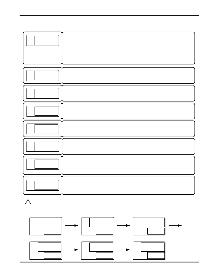
Output Gr oup Menu Pr ogression Example:
?
The following settings establish relay out put 1 (OUT1) to trigger based on alarm 1, for analog output 2 (OUT2) to
NOTE
operate as a heating temperature controller outputting a voltage pulse, for analog output 3 (OUT 3) to output a
retransmitting 4-20 mA signal, and for auxiliary r elay o utp uts SU B1 and SUB2 to trigger with alarm 2 and alarm 3.
PV
oUT1 oUT2
SP
alm1
Press SET/ENT key to sele ct i nput group. ( Refer to par ameter map in section 3.)
G.AT G.SP G.PID PWD G.CTL G.IN
G.COM G.RET G.ALM G.OUT
This par a me t e r se t s t h e t y p e o f operat i o n for output 1. (OU T1: relay out p u t )
Th e o u t p u t can b e s et t o HEAT, COO L , ALM 1 , AL M 2 , ALM 3 , or RUN. Its de f au l t setting is
ALM1. (COOL is disp l a yed o n H/C models only. Skip wh e n ON/OFF M ode selected.)
This parame t e r e st a b l is h e s th e t ype o f operation for output 2. (OUT2: 4-20 mA or voltage
pulse) Setti n g s c a n b e HEAT , COO L , or RET (retransmitting ). Its de f a u lt sett in g i s
HEAT. (COOL is dis pl a yed o n H/C models only.)
This parameter estab l is h e s t h e t ype of oper ation for output 3. (O UT 3: 4- 20 mA or voltage
pulse) Settings can be HEAT, COOL, or RET (retransmitting). Its default setting is
HEAT. (COOL is displayed on H/C models only.) Valid for models with OUT3 only.
This parameter selects the ty p e o f o u t pu t s i gnal for each analog output (OUT 2 and O UT3)
when they are set to HEAT. The outputs can be set to SSR (pulse output) or
SCR (4-20 mA). Its default setting is SSR.
This parameter selects the ty p e o f o u t pu t s i gnal for each analog output (OUT 2 and O UT3)
when they are set to C OOL. The outp u t s c a n b e s e t t o S SR (puls e o ut p u t ) or S C R ( 4 20mA). Its d ef a u l t se t t i n g i s S SR.
This para me t e r s e t s th e type of oper ation for auxiliary outp ut 1 (SUB1: relay outp ut )
Output can be set to HEAT, COOL, ALM1, ALM2, ALM3, or RUN. Its default setting is
ALM2. (COOL is disp l a y ed on H/C models only. Menu appears only on models with t h e
SUB1 output option.)
This parameter sets t h e t y p e o f oper ation for aux ilia r y out put 2 ( SU B2: re lay o utp ut )
Output can be set to HEAT, COOL, ALM1, ALM2, ALM3, or RUN. I ts default setting is
ALM2. (COOL is displayed on H/C models only. Menu appears only on models with the
SUB2 output option.)
PV
SP
HEAT
PV
HEAT
SP
ssr
PV
oUT3
SP
ret
PV
sUB1 SUB2
SP
alm2 Alm3
19
PV
SP
Page 20
PD540 Series Nova Digital Process and Temperature Controller Instruction Manual
PV
o.Act
PV
ct
PV
ctC
PV
oH
PV
oL
PV
HYS
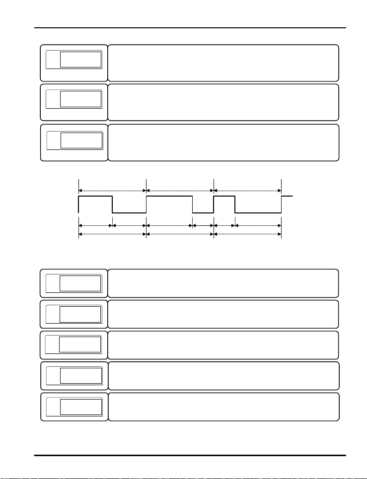
This parame t e r e s t a b li sh e s rev e r s e (REV) or fo r w a r d (FWD) activation of th e c o n t r o l
outputs . I n fo r ward ope r atio n, t he cont r ol ou tpu ts will be most a ctive when the PV value is
higher than the SP, as th e c on t rolle r a c t s t o l o we r t h e P V. In rev e r s e operation, the control
outputs will be most act ive when the PV value is lower than the SP v alue, as the controlle r
acts to increase t h e PV . The defa u lt s e t t in g i s REV.
This parameter estab li s h es t h e cycle t i me f o r use wit h t i me - p r opor tional PID relay or
voltage pulse control whe n t h e o u t p u t s a re set t o H E AT or COOL. T h e cycle t ime c a n be
set f r o m 1 t o 3 00 seconds. It s d e f a u l t se t t i n g i s 2 s e co n d s .
This parameter estab l is h e s t h e c y c le t i me f o r c oo l i n g ou t p u t s if coolin g (COOL) cont r o l is
set u p wi t h time-prop o rtion a l PID contr o l i n a H/C model. (Ex ample: OUT1 = Cool, OUT2
or Out3 = Co o l a n d s e t t o SSR, SU B1 or SUB2 = Cool) Th e c ycle ti me ca n b e s e t f r o m 1
to 300 seconds. Its default setting is 2 seconds.
Output at 50%
5 Sec
5 Sec
CT = 10 Sec
Fig 3: Time-Proportional PID Control Output
This para me t e r s e t s a high limit for the le vels of th e c o n t r o l ou t p u t . This limits t h e o u t p u t
levels based on a percent ag e o f t h e i r f u l l s ca l e . Its de f a u l t se t t i n g is 100 (% ).
This parameter sets a lo w l imi t f o r t h e l evels of t h e co n t r o l o u t p u t . This prevents th e
outputs from droppi n g b e lo w a c e r t a i n le vel based o n a p e rcent age of their full scale. Its
default setting is 0 (%). The outp u t s a re limit e d b y b o t h t h e t h e l o w a n d h i g h l imits.
This parameter set s h y s t e r e s is in c a se o f On/O f f c o n t r o l ou t p u t mode in a H/C model.
Output at 70% Output at 30%
7 Sec
CT = 10 Sec CT = 10 Sec
Cycle Time (CT) set t o 1 0 s ec o n d s
3 Sec
3 Sec
7 Sec
PV
HYS.H
PV
HYS.L
This parameter sets t h e hysteresis h i g h li mit f o r on/o f f relay cont r o l mode in normal
models (non-Heating/Cooling models).
This parameter se t s t h e h y s t e r e s is lo w l imi t f o r o n / o f f r e l a y c o n t r o l mode in normal models
(non-Heating/Cool in g models).
20
Page 21
PD540 Series Nova Digital Process and Temperature Controller Instruction Manual
PV
po
PV
poC
Output Group Parameter Summary
Display Parameter
OUT1
Select Output
OUT2
Select Output
OUT3
Select Output
Select Output
HEAT
Select Output
COOL
SUB1
Select Output
SUB2
Select Output
Reve rse and
O.ACT
HYS.H Hysteresis Hi g h
HYS.L Hysteresis Low
OUT1 Relay
Condition
Forward
CT
Cycle Time 1
CTc Cycle Time 2
High Limit value
OH
of Output
Low Limit val u e
OL
of Output
HYS Hysteresis
PO
Preset Output
POc Preset Output
OFF
SP SP
Note: In H/C models, HYS.H and HYS.L replaced by HYS, and range high and low is 1/2 HYS setting
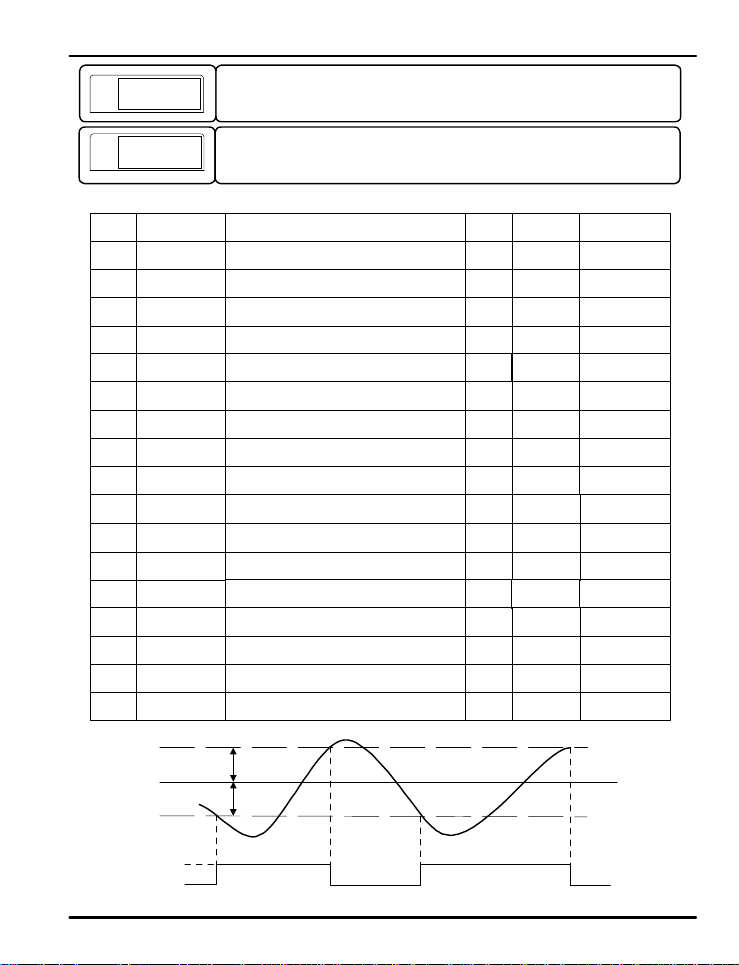
This parameter establishes the percent output transmitted by the control outputs when the
controller is in STOP mode, or when an error condition occurs such as a PID algorithm
error, A/D error, or open sensor error is detected.
This parameter e st a b l is h e s t h e p e rcent o u t p u t t r a n s mit t e d b y t h e C OOL c o n t r o l o u t p ut s i n
a Heating & Cooling controller model when the controller is in STOP mode, or when an
error condition occurs.
ON
Type
Type
On
Off
Setting Range
HEAT, COOL, A L M 1 , A L M 2 , AL M 3 , RUN
HEAT, COOL , RET
HEAT, COOL , RET
SSR, SCR
SSR, SCR
HEAT, COOL, A L M 1 , A L M 2 , AL M 3 , RUN
HEAT, COOL, A L M 1 , A L M 2 , AL M 3 , RUN
REV, FWD
1 to 300 sec
1 to 300 sec
OL + 1 digit to 105.0%
HC models: 0 to 105.0%, however OH>OL
-5.0% to OH setting
HC Type: 0 to 105.0%, However OH>OL
0.0 to 10.0 %
GEU (0.0 t o 10.0% of se n s o r r a n g e )
GEU (0.0 to 10.0% o f se n s o r r ange)
-5.0 to 105.0%
H/C Type : 0.0 to 105.0%
0.0 to 105.0%
HYS.H
PV
HYS.L
On/Off Relay Be h a vior Base d O n H ysteresis S e t t in g s
21
Unit Default Remark
ABS ALM1
ABS HEAT
ABS RET
ABS SSR
ABS SSR
ABS ALM2 Option
ABS ALM3 Option
ABS REV
sec 2 sec
sec H/C Models Only
%
100.0%
%
H/C:100.0%
%
GEU
GEU (0.5%)
GEU
GEU (0.5%)
%
% H/C Models Only
ON
2 sec
0%
0.5%
0.0%
0.0%
Models with
OUT3 Only
When OU T 2,
3, Set for HEAT
When OUT 2,
3, Set for COOL
H/C Models Only,
On/Off Mode
Relay Cutoff,
ON/OFF Mo d e
Relay Activation,
ON/OFF Mo d e
PV
Page 22
PD540 Series Nova Digital Process and Temperature Controller Instruction Manual
5.3 Control Group (G.CTL)
PV
g.ctl
PV
s-tm
PV
p-tm
PV
A/m
PV
US1
PV
US2
PV
LoCk
Table 2: DI Operation
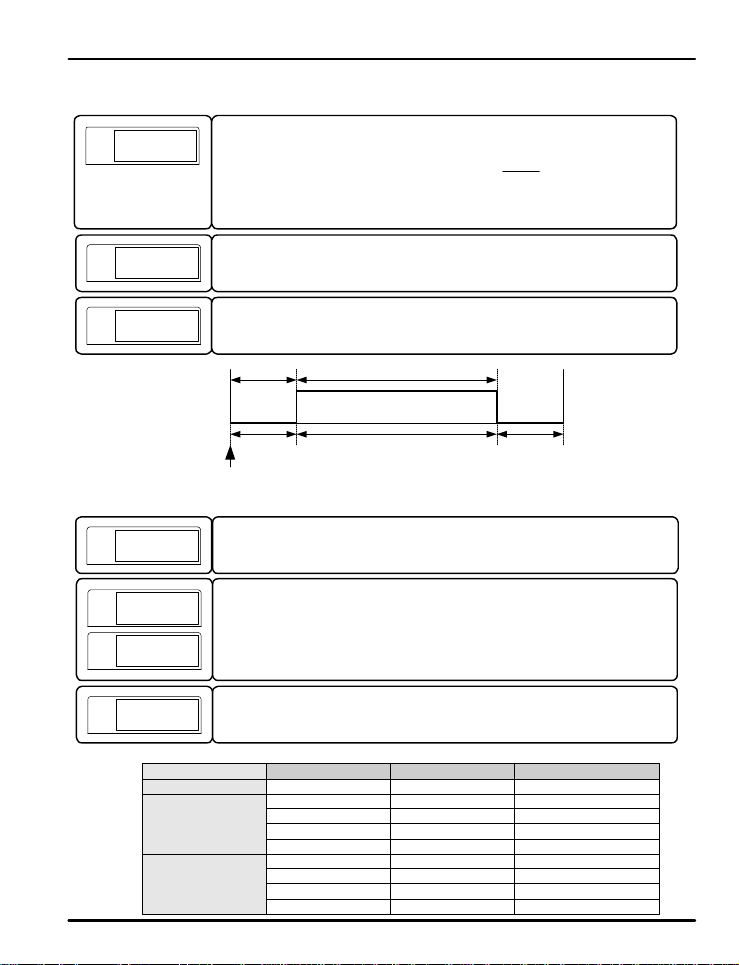
Press SET/ENT key to select control group. (Refer to parameter map in section 3.)
G.AT G.SP G.PID PWD G.CTL G.IN
G.COM G.RET G.ALM G.OUT
This parameter establishes the delay time from power on to when the outputs are activate d .
This can be set from 0 to 99.95 (hours.min u t es ) . Its defau l t se t t i n g is OFF. S e e F i g . 4 .
This parameter establishes the running time for the controller outputs. P-TM can be set
from to 99.59 (hours.minut e s). I t s d e f a u lt s e t t i ng i s O F F. See Fig 4. N o t e t h a t t h is t ime
begins after the S- TM functi o n .
S-TM P-TM
STOP RUN STOP
POWER ON
Fig 4: Output Delay and Timer Functions
This establishes the con t r o l mo d e a s a u t o ma t ic ( A U TO) or manual (MAN). When in
manual mode, the output levels can be set by the user from the operation display, and the
MAN LED will active on the front panel. The default setting is AUTO.
This parameter estab l is h e s t h e u s e r sc r eens for viewing, confirmation, and setup of
commonly used parameters from the operation display. To add the parameter to t h e
operation display , e n t er the co rresponding number for the parameter from the Table of DRegisters as either US1 or US2. The de f a u l t se t t i n g s a re OF F.
See page 14 and the Operation Flow Chart for a map of the operation display.
&
Turning ON this parameter locks all setting s fr om bein g changed. This applies to the
operation display f u nc t i o n s, s u ch a s c h anging the set point, as well as setting group
parameters. If ON, on l y t h e L OCK pa ramete r may b e changed. The default setting is OFF.
DI.SL DI1 DI2 Operation
OFF - -
1
2
off
on
-
off
on
off
on
off SP1
on SP2
off
off
on SP3
on SP4
-
-
DI Disabled
Stop
Run
SP1
SP2
22
Page 23
PD540 Series Nova Digital Process and Temperature Controller Instruction Manual
PV
di.sl
PV
osts
PV
dsp.H
PV
dsp.l
PV
U.pwd
!
CAUTION
PV
onof
?
NOTE
&
PV
init
This parameter establishes the operation of the digital input (DI) ex ter nal contacts. The
digital input operating configurati on s a r e s h o wn in Table 2: D I Ope r a t i o n . This feat u r e i s
only val id f o r mo d e l s wi t h d ig i t a l i nputs.
When this parameter is on , th e o utp ut sett ing s will be disp lay e d in t he ope r atio n d isplay .
The settings of parameter s OUT 1 , O UT2 , O U T3, SUB1 , a n d SU B 2 will be sho wn. O nly
outputs built into th e mod e l b e in g u s e d will displa y . Its default sett ing is O FF .
This parameter sets t h e h ig h l imi t o f t h e s e n so r inpu t i n t h e P V d is p l ay. T h e P V value will
not display higher than this limit, however the control functions will operate based on the
actual input value.
This parameter se t s t h e lo w l imi t o f t h e s e n so r inpu t i n th e P V d is p la y. T h e P V value will
not display lower than this limit, however the control functions will operate based on the
actual input value.
This parameter estab l is h e s t h e p a s swo r d f o r the co n t r o l le r. T h i s p a s swo rd must b e
entered at the PWD screen before accessing the control group (G.CTL) or it will not
access the settin g gr o u p s a f t e r the P WD p r o mp t . The defau l t se t t i n g i s " 0 " . S e e t h e
parameter map in section 3 for the location of the PWD prompt in the group menus.
Be sure not to forget the password once it has been set. If the passwor d i s f o rgott e n , c o n t a ct t e c h n ic a l
support as listed on the back of this manual.
The pa r a me t e r t o s e t the cont r o l t y p e f o r On/O f f control mode in a He a t i n g o r C o o l in g
standard cont rolle r . Contr o l o u t p u t is set to ou t p u t 1 ( O u t 1 : R e l a y ) when in On/O f f m ode.
See hysteresis commands in the output group for operating the relay in On/Off mode.
The onof parameter does not appear in Heating and Cooling controllers. To set up a Heating and
Cooling model for O n / Off co n t r o l , e n t e r t h e G.PID (PID Group) and set parameters 1.P and 1.Pc to 0.0.
See page 20 and 21 for more information on setting up On/Off control.
This parameter rese t s mo st p a ramete r s t o t h e ir fact o ry set t i n g s. To reset the co n t rolle r ,
set this parameter to ON. Afte r res et , i t will r et ur n t o t he O F F set tin g.
!
CAUTION
Most parameters will be reset to th e ir defa u l t se t t i n g s when the controller is initialized. Note the current
settings before this is done so they can easily be restored after controller initialization.
23
Page 24
PD540 Series Nova Digital Process and Temperature Controller Instruction Manual
Control Group Parameter Summary
Display Parameter
S-TM Start Time Delay
P-TM Process Run Time
A/M Automatic/Manual
US1
US2
LOCK
DI. SL
OSTS
DSP.H
DSP.L
U.PWD User Password
ONOF ON/OFF Mode
INIT
User Screen
User Screen
Parameter Lock
DI Selection
Output Status
Display
Display High Limit
Display Low Limit
Factory
Initialization
Setting Range
Off (0.00 ) t o 99. 5 9 (hours.minutes)
Off (0.00) t o 9 9 . 5 9 (hours.minutes)
AUTO, MAN
Off, D-Register Number 1 to 1299
Off, D-Register Number 1 t o 1299
OFF, ON
OFF, 1, 2
OFF, ON
AEU (-5.0 to 105.0%), DSP.L<DSP.H
AEU (-5.0 to 105.0%), DSP.L<DSP.H
0 to 9999
ON, OFF
OFF, ON
Unit Default Remark
Time OFF
Time OFF
ABS AUTO
ABS OFF
ABS OFF
ABS OFF
ABS OFF DI Option
ABS OFF
AEU AEU (105.0%)
AEU AEU (-5.0%)
ABS 0
ABS OFF
ABS OFF
Not in
H/C Models
24
Page 25
PD540 Series Nova Digital Process and Temperature Controller Instruction Manual
5.4 SP Group (G.SP)
PV
g.sp
PV
r-s
PV
spsl
PV
sp1
PV
sp4
PV
sprh
PV
sprl
PV
tmU
PV
U.SLP
PV
D.SLP
Press SET/ENT key to sele ct S P g r oup. ( Refer to par ameter map in section 3.)
G.AT G.SP G.PID PWD G.CTL G.IN
G.COM G.RET G.ALM G.OUT
This parameter sets the running mode to RUN or STOP. I n ST O P mode, outputs are
turned off, and no set point is maintained.
This parameter selects whi c h se t p o in t i s a ct i ve. The r e a re fou r pro g r a mma b le s e t p o in t s ,
and one for use with SYNC- SLAVE communication. I t can b e set t o RSP, SP1, SP2, SP3,
or SP4. Its default setting is SP1.
When using the communication option for Sync-Slave control, the slave
?
controllers must have SPSL set t o RSP.
NOTE
This parameter sets the value of each of the 4 programmable set points that can be
.
.
.
selected t o r u n . The para me t e r SPSL selects which set poin t to use.
This par a me t e r sets a hig h l imi t o n wh a t th e s e t p o in t s ca n b e p rogr a mmed o r c hanged to.
This value may reset if the t y p e o f i nput is changed, or if parameter IN.RH or I N.RL
(IN. SH or IN.SL if input type is mV or V) is changed.
This par a me t e r se t s a lo w l imi t o n wha t t h e s e t p oi n t s c a n b e p r o g r a mme d o r changed to.
This value may reset if the t y p e o f i nput is changed, or if parameter IN.RH or I N.RL
(IN. SH or IN.SL if input type is mV or V) are changed.
This parameter sets the time unit the controller uses for parameters with time components.
This can b e s e t t o t h e f o r ma t o f HH.MM (hours.min u t e s) or MM.SS (minute s . se c o n d s).
Its de f a u l t setti n g is HH.MM.
This parameter to sets the SP to ascend or descend gradually over time, dependant on t h e
new SP se l e ct e d . U.SLP (ra t e o f a sc e n si o n ) a n d D.SLP (ra t e o f d e sc e n t ) ar e t h e r at e of
change over ti me ( t i me u n i t s s e t b y p a ramete r TM U ) o f t h e s e t p o in t wh e n t h e se t p o i n t is
changed. When U.SLP and D.SLP is set to OFF, the new SP is set instantly. The default
setting of U . S L P a n d D . SL P is OFF.
Parameters S-TM and P-TM are n o t li n ke d t o TMU. T h e t i me u n it s e t t in g
?
of those paramet e rs is al wa y s H H . M M ( hours.minutes).
NOTE
25
Page 26
PD540 Series Nova Digital Process and Temperature Controller Instruction Manual
Set Point Group Parameter Summary
Display Parameter
R-S Run/Stop
SPSL
SP1
SP2 Set Point 2
SP3 Set Point 3
SP4 Set Point 4
SPRH
SPRL
TMU Time Unit
U.SLP
D.SLP
SP Select
Set Point 1
Set Point
Range High
Set Point
Range Low
Rate of Chage
for SP I n c r e a s e
Rate of Chage
for SP Decrease
Setting Range
RUN, STOP
RSP, SP1, SP2, SP3, S P4
AEU (0.0 - 100.0% of input range)
AEU (0.0 - 100.0% o f i nput range)
AEU (0.0 - 100.0% o f i nput range)
AEU (0.0 - 100.0% o f i nput range)
AEU (0.0 - 100.0% o f i nput range)
AEU (0.0 - 100.0% o f i nput range)
HH.MM (hours.minutes),
MM.SS (minut e s . se c onds)
OFF (0), GEU (0.0%+1digit t o 100 . 0 % ) p e r
OFF (0), GEU (0.0%+1digit to 100.0%) per
minute or second
minute or second
Unit Default Remark
ABS RUN
ABS SP1
AEU (Input
AEU
Range Low)
AEU (Input
AEU
Range Low)
AEU (Input
AEU
Range Low)
AEU (Input
AEU
Range Low)
AEU (Input
AEU
Range High)
AEU (Input
AEU
Range Low)
ABS HH.MM
GEU OFF (0)
GEU OFF (0)
26
Page 27
PD540 Series Nova Digital Process and Temperature Controller Instruction Manual
5.5 PID Group (G.PID)
?
NOTE
PV
The PID group selection doe s n o t a p p e a r when the controller is operating in On/Off mode
Press SET/ENT key to select PID group. (Refer to parameter map in section 3.)
G.AT G.SP G.PID PWD G.CTL G.IN
G.COM G.RET G.ALM G.OUT
PV
PV
C.mod
PV
PV
PV
The parameter sets the PV deviation width to prev ent overshoot. When the control output s
reach this high limit value, th e y stop o r d i n a r y outp u t a c t io n f o r inte g r a l co n t rol an d u se
ARW (Anti-Reset Windu p ) . When the setting is AUTO, this parameter is calculated
automatically.
This par a me t e r establishes the c on t rol mode. It can be set to Differential of Deviation Value
(d. dv) or Process Variable (d. pv). Dviation Value mode will reduce overshoot. Process
Variable mode will more quickly raise and lower the PV. The def au lt setting i s d . d v.
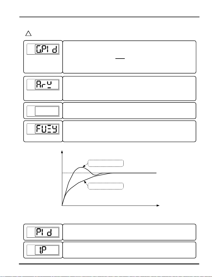
This parameter act i vates the u s e o f f u zzy logic. Fuzzy logic c a n b e e f f e c t ive in
suppressing overshoo t a n d reducing PV variation that may occur once the PV has reached
the SP. Ref er to F i g 5: Oversh o o t S uppression with Fuzzy Logic.
PV: Fuzzy Logic Off
SP
PV: Fuzzy Logic On
Fig 5: Overshoot Suppression with Fuzzy Logic
This parameter esta b l is h e s t h e n u mb e r o f P ID set t i n g g r oups to be used in control output
calculation. Up to 4 user defined groups of proportional, integral, and derivative v alue
zones can be established. U se t h i s s e t t i n g t o e n t e r the s e t t in g menus for each PI D group.
This par a me t e r s e t s th e proport i onal operation for PID control.
Setting rang e o f 1 . P is 0.1 (H/C mod el: 0.0 ) to 999.9%.
Its default setting is 10.0%.
27
Page 28
PD540 Series Nova Digital Process and Temperature Controller Instruction Manual
PV
PV
PV
PV
PV
PV
PV
.
.
.
PV
PV
PV
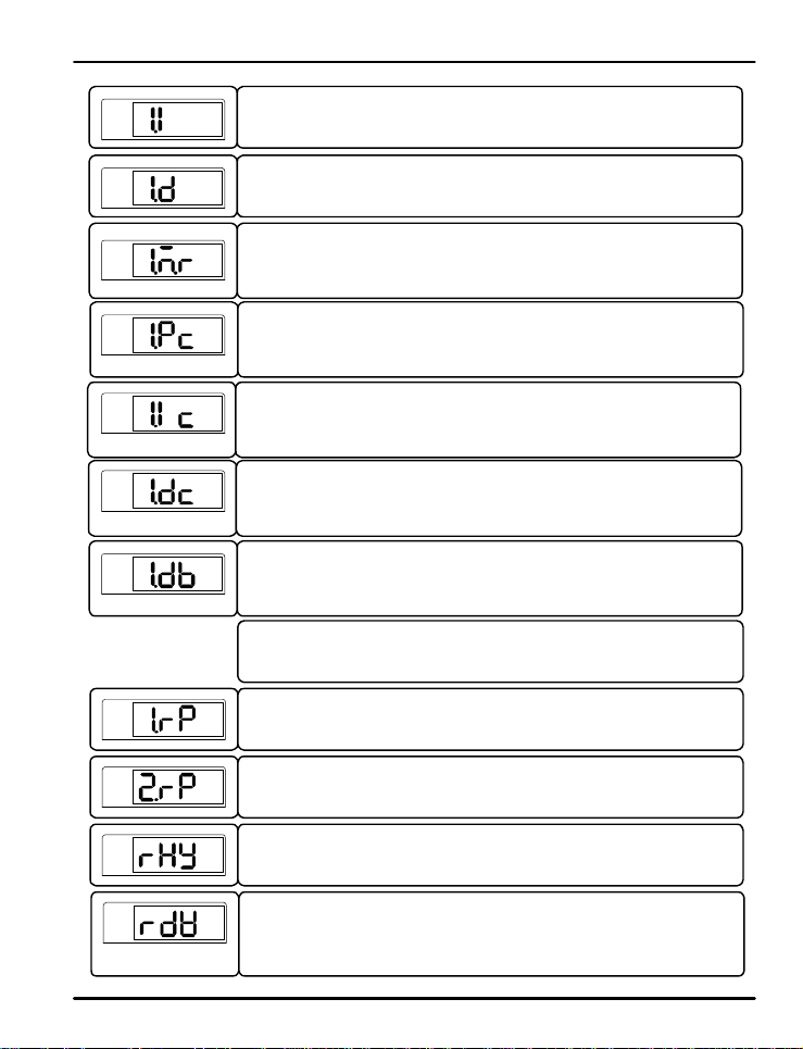
This par a me t e r s e t s th e integrati o n t im e for PI D cont rol.
Setting range s of 1. I are OFF or 1 to 60 00 seconds.
Its default setting is 120 seconds
The parameter to set derivation time for PID control.
Setting range s of 1.D ar e OFF or 1 t o 6 0 00 se c onds.
Its default setting is 30 seconds.
The p a r a me t e r to set the manual reset in th e PID calcula t i o n . This sett in g o n l y f u n c t i o n s i f
the integral time sett in g i s OFF. This sett i n g al wa ys fun ct i o n s for H/C mod els.
The pa r a me t e r t o s e t p roportion a l operation for PID control for the cooling control in
H/C models . Setting op t i o n s a r e 0. 0 (whe n using On/Of f control) o r 0 . 1 t o 999.9% .
Its default setting is 10.0%.
The p a r a me t e r to set integral ti me for PID control for t h e cooling control in H/C models.
Setting op t io n s a r e OFF or 1 t o 60 00 secon ds.
Its default setting is 120 seconds.
The pa r a me t e r t o s e t d eri vative t im e for PID control f o r the cooling contr o l in H/C mode ls.
Setting options are OFF or 1 to 6000 seconds.
Its default setting is 30 seconds.
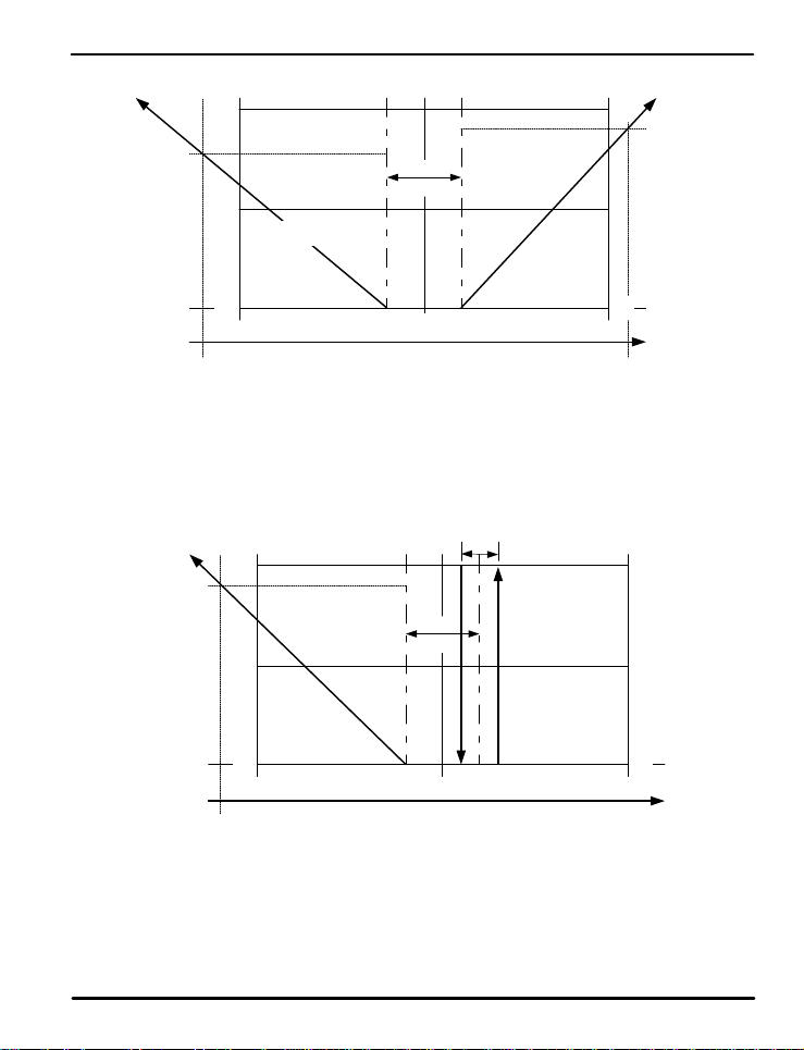
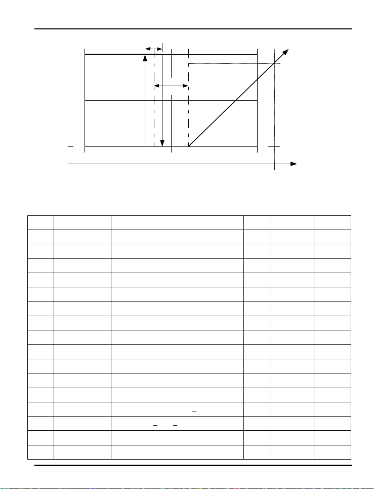
The parameter to set the dead band, in which there is n o o u t p u t f r o m e it h e r the he a t i n g o r
cooling outputs. Refer to F i g 6 , Fig 7, and Fig 8.
Note: The contents of PID Groups 2, 3, and 4 are the same as PID Group 1.
This parameter establ is h e s t h e P V range of each of the 3 main PID zones. The range of
PID zone 1 is IN.RL (IN.SL if set for mV or V input) to 1.RP. The r ange of PI D zone 2 is
1.RP to 2.RP. The range of PID zone 3 is 2. R P t o IN.R H ( IN.SH if s e t f o r mV o r V i nput).
This parameter establish e s t h e r a n g e o f e a ch o f t h e 3 ma i n P ID zones . The range of PID
zone 1 is IN.RL (IN.SL if set for mV or V input) to 1.RP. T he range of PI D z one 2 is 1.RP
to 2.RP. The range of PID zone 3 is 2.RP t o IN.R H (IN . SH i f s e t f o r mV o r V inp u t ) .
This paramete r e st a b l is h e s t h e h ysteresis wi dt h o f t h e P ID zo n e .
PV
This paramet e r sets th e range o f d e viation f o r P ID z one 4. When the difference between
the PV and SP is greater than this deviation range, the controller will utilize PID group 4
for PID settings. While t h e P V a n d S P a r e wi t hi n t h i s d e viation d i f f e r e n ce , t h e c o n t r o l le r
will utilize whatever zon e would n or mally b e use d ba sed o n th e PV value .
28
Page 29
PD540 Series Nova Digital Process and Temperature Controller Instruction Manual
COOL
(80%)
COOL
100
OL
50
P/Pc = 4/5
0 0
0 50 100
OL-LIMIT
(-5%)
OL
(90%)
Fig 6: Heating and Cooling Outputs Using PID Control
100
50
Dead Ban d
(1.DB at 2 0 % )
Output
HYS
Dead Ban d
(1.DB at 2 0 % )
HEAT
100
50
OH-LIMIT
(100%)
100
50
OH
(90%)
HEAT
0 0
0 50 100
OL-LIMIT
(-5%)
Fig 7: Heating On/OFF and Cooling PID Outputs
OUTPUT
29
OH-LIMIT
(100%)
Page 30
PD540 Series Nova Digital Process and Temperature Controller Instruction Manual
100
50
0 0
0 50 100
OL-LIMIT
(0%)
PID Group Parameter Summary
Display Paramete r
ARW
Anti-Reset Wind-Up
C.MOD Control Mode
FUZY
PID
n.P
n.I
n.D
n.MR n.Manual Reset
n.Pc
n.Ic
n.Dc
n.DB n.Deadband
1.RP Reference Point 1
2.RP Reference Poin t2
RHY
RDV
Fuzzy
PID Number
n.Proportional Band
n.Integra l Time
n.D erivative Time
n.Proportional Band
for Cooling Side
n.Integral Time for
Cooling Side
n.Derivative Time for
Cooling Side
Reference
Hysteresis
Reference
Deviation
COOL HEAT
Fig 8: Heating PID and Cooling On/Off Outputs
HYS
DB
(20%)
OUTPUT
Setting Range
Auto or 50.0 to 200.0%
Differential of Deviati on V a l u e ( d . d V ) o r
Process Variabl e ( d . P V )
OFF, ON
MENU (0), 1, 2, 3, o r 4
0.1 (H/C Models:0 . 0 ) to 999.9%
OFF, 1 to 6 0 0 0 s e c onds
OFF, 1 to 6 0 0 0 s e c onds
-5.0 to 105.0%
0.0 (ON/OFF Control) o r 0.1 to 9 9 9 .9%
OFF, 1 to 6 0 0 0 sec
OFF, 1 to 6000 sec
-100.0 to 50.0%
AEU (0.0%), 1 . R P < 2 . R P
1.RP < 2.RP < AEU (100.0%)
GEU (0.0 t o 1 0 . 0 % )
GEU (0.0 t o 1 0 0 . 0 % )
100
OH
(90%)
50
OH-LIMIT
(105%)
Unit Default Remarks
% Auto
ABS d. dV
ABS OFF
ABS MENU
% 10.0%
sec 120 sec
sec 30 sec
% 50.0%
% 10.0%
sec 120 sec
sec 30 sec
% 3.0%
AEU 100.0% PID Zone 1
AEU 100.0% PID Zone 2
GEU 0.3% PID Zone 3
GEU 0.0% PID Zone 4
Used if I =0 ,
or H/C Model
H/C
Models Only
H/C
Models Only
H/C
Models Only
H/C
Models Only
30
Page 31
PD540 Series Nova Digital Process and Temperature Controller Instruction Manual
5.6 Aut o -Tuning Group (G.A T)
?
AT group selection does not appear if operating in On/Off mode or when set for manual output control.
NOTE
PV
Press SET/ENT key to select AT group. (Refer to parameter map in section 3.)
G.AT G.SP G.PID PWD G.CTL G.IN
G.COM G.RET G.ALM G.OUT
PV
?
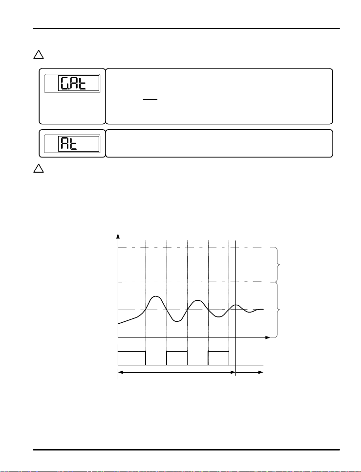
Auto-Tuning (AT)
NOTE
The auto-tuning feature is u se d t o l e t t h e co n t r o l l er measu r e p rocess ch a racte r i s t ic s and automatically set the most
appropriate values for the PID para me t e r s . D u r i n g t h e i n i t ia l a u t o - t u n in g p roces s, t h e co n t rol ou t p u t s will f un ction
in an On/Off condition, and the controller will use the r esponses to calculate the needed PID values. During this
setup process, the M A N L ED on th e c o n t r o l le r will b link.
Start the auto-tuning process after se t t i n g a d es i r e d se t p o i n t . A ut o -tun in g will set the PI D par a meter s for t he PID
zone which the set p o in t i s i n , b a se d o n t h e P ID re f e r e n c e p o in t (RP) e n t e r e d .
The parameter to activate the auto-tuning function.
When AT is set to ON, auto-tuning will begin (indicated by the MAN light blinking). This
parameter cannot be used if the controller is in STOP mode.
RH
RP
SP
RL
ON OFF ON OFF ONControl Output
Auto-Tu n in g On
(On/Of f Oper a t i o n , MAN LED Blinki n g )
PID Control
Fig 9: Auto-Tuning
2.PID
1.PID
31
Page 32
PD540 Series Nova Digital Process and Temperature Controller Instruction Manual
Auto-Tuning the Heat in g / C o o l i n g Outp u t s:
Auto-tuning of the heating/cooling outputs is the same process as the normal outputs. The PID heating/
cooling parameters wil l be cal cu l a t e d . The p a r a me t e r s f o r t h e P ID deriv a t io n t i me ( 1 . D ) will be the same for
both the heating and cooling outputs.
Display During Auto-Tuning:
The MAN LED on the fr on t pa ne l will blink at a 50 0 ms time inter val.
Changing the Set Point During Auto-Tuning:
If the set point is changed during the auto-tuning process, the original set point will be maintained fo r the
duration of the auto-tun i n g p r o c e ss . Af t e r auto -tuni n g i s c o mpl e t e , t h e co n t roller will change to the new set
point.
Changing PID Parameters During Auto-Tuning:
The PID values can be change d d u r i ng t h e a u t o -tuni n g p r o c e ss . Af t e r auto -tun in g i s c o mpl e t e , it will t he n
use the auto-tune calculate d P ID v a l u e s. V a lu e s ch a nged after auto-tuning will remain set un til au to -t un ing is
run again.
Auto-Tuning Interruption s o r E r rors :
The auto-tunin g p r o c e ss will end without effect for any of the following reasons:
- Auto-tuning forced t o end ( Ex ample: Controller power down or stop condition)
- Open sensor (S.OPN) input erro r dete c t e d d u r i n g t h e a u t o -tuni n g p r o c e ss
- Auto-tuning cycle exceeds 24 hours.
- Control changed to manual (MAN) operation during auto-tuning.
PV
Auto-Tuning Group Parameter Summary
Display Parameter
AT
AT-G
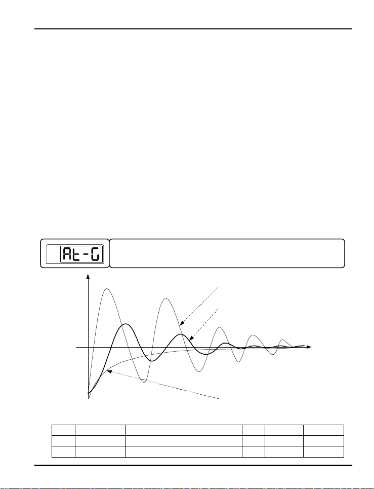
This parameter affects the proportional v alue deriv ed by auto-tuning. Reduce the AT -G
gain value and the cycle becomes more rapid, but more unstable. Increasing gain slows
system react ion time, b ut sy stem sta bility in cr ea ses.
Fig 10: Auto-Tuning Gain
Auto-Tuning
AT Ga i n
Setting Range
OFF, ON
0.1 to 10.0
32
Gain < 1
Gain = 1
Gain > 1
Unit Default Remark
ABS OFF AT Activation
ABS 1.0 Gain Value
Page 33
PD540 Series Nova Digital Process and Temperature Controller Instruction Manual
5.7 Alarm Group (G. A L M )
PV
G.alm
PV
alt1
PV
al-1
PV
al1.H
PV
al1.l
PV
a1db
PV
a1dy
.
.
.
?
Alarm Types and LED Display
NOTE
SP
AH.FS
Press SET/ENT key to select a l a r m g r oup. ( Refer to par ameter map in section 3.)
G.AT G.SP G.PID PWD G.CTL G.IN
G.COM G.RET G.ALM G.OUT
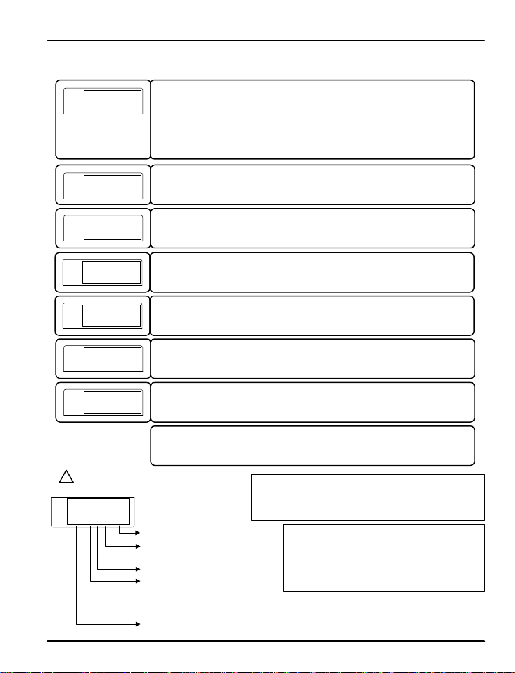
This parameter sets the type of alarm to be set for alarm 1.
The t ypes of a la r ms select a b le a re sho wn i n Table 3: Al a r m S e l e ct i o n .
This parameter sets the alarm trigger point for the alarm set in ALT1.
This par a me t e r displays if a high, l o w, o r h ig h a n d l o w li mit a l a r m wa s se l e ct e d f o r A L T1.
This establishes the high deviation range to trigger the alarm of deviation. T his parameter
displays if a deviation alarm was selected in ALT1.
This establishes the low deviation range to trigger the alarm of deviation. This parameter
displays if a deviation alarm was selected in ALT1.
This parameter sets the dead band (Hysteresis) o f a l a r m 1.
This par a me t e r se t s the d e lay time before of a la rm 1 is triggered.
Note: The menus for alarm 2 and 3 are the same as alarm 1.
Alarm Output Settings:
- Forward : Relay energiz e d i n a la rm condition
- Rever se : Failsafe operation. R e la y energiz e d d u r i ng n o rmal
operatin g conditions
S indicates standby operation
F for forward operation
r for reverse (failsafe) operation
Decimal point always displaye d
H indicates a high alarm
L indicates a low alarm
o for outside range of deviation band
I for inside range of dev iation band
A indicates an absolute value alarm
d indicates a deviation alarm
Standb y Operation:
The alarm will not trigger if the alarm condition
occurs during the fo l l owi n g a ct i vities.. .
- during power-up
- the set point is changed
- the type of alarm is changed
33
Page 34
PD540 Series Nova Digital Process and Temperature Controller Instruction Manual
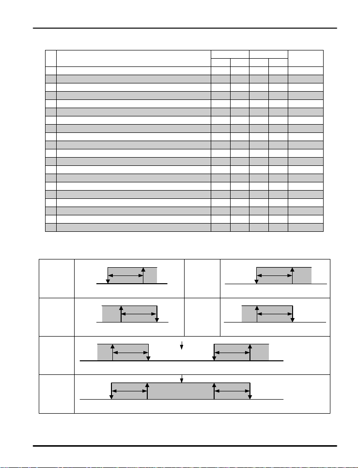
Table 3: Alarm Selection
No.
1
2
3
4
5
6
9
10
11
12
13
14
15
16
17
18
19
20
Alarm Typ e
Absolute V a lu e H i g h L imi t Al a r m
Absolute Value Low Limit Alarm
High Limit Dev i a t i on A l a r m
Low Limit Deviation Alarm
High Limit Dev i a t i on A l a r m
Low Limit Deviation Alarm
High and Low Limit Deviation Alarm7
High and Low L imi t R ange Deviation Alarm8
Absolute V a lu e H i g h L imi t Al a r m
Absolute Value Low Limit Alarm
Absolute Value High Limit Alarm with Standby
Absolute Value Low Limit Alarm with Standby
High Limit Deviation Alarm with Standby
Low Limit Deviation Alarm with Standby
High Limit Deviation Alarm with Standby
Low Limit Deviation Alarm with Standby
High and Low Limit Deviation Alarm with Standby
High and Low Limi t R ange Dev iation Alarmwith Standby
Absolute Va lu e H i g h L imi t A l a r m with Standby
Absolute Value Low Limit Alarm with Standby
Operation
For
3
3
3
3
3
3
3
3
3
3
3
3
Rev
Standby
On
3
3
3
3
3
3
3
3
3
3
3
3
3
3
3
3
3
3
Off
3
3
3
3
3
3
3
3
3
3
Display Data
AH.F
AL.F
DH.F
DL.F
DH.R
DL.R
DO.F
DI.F
AH.R
AL.R
AH.FS
AL.FS
DH.FS
DL.FS
DH.RS
DL.RS
DO.FS
DI.FS
AH.RS
AL.RS
PV High
Limit Alarm
PV Low
Limit Alarm
High and Low
Limit D evi a t i o n
Alarm
High and Low
Limit Range
Deviation
Alarm
DEV
-
DEV
-
PV
PV
OFF
ON
ALM.L
OFF
ON
ALM
ON
DB
ALM
DB
OFF
DB
OFF
ON
DB
ALM.L
Fig 11: Ala r m Operation
DEV=0
SP
DEV=0
SP
34
High Limit
Deviation
Alarm
Low Limit
Deviation
Alarm
OFF
ON
ALM.H
DEV
-
OFF
SP
ON
DEV
- +
SP
ALM.L
ON
DB
ALM.H
DB
OFF
ON
DB
ALM.H
DB
OFF
+
+
+
Page 35
PD540 Series Nova Digital Process and Temperature Controller Instruction Manual
Alarm Group Parameter Summary
Display Parameter
ALT1
AL-1
AL1.H
AL1.L
A1DB
A1DY
ALT2
AL-2
AL2.H
AL2.L
A2DB
A2DY
ALT3
AL-3
AL3.H
AL3.L
A3DB
A3DY
Setting Range
Alarm Type 1 Refe r to Ta b l e 3: Alar m S e l e ct i o n ABS AH.F
Set Value of
Alarm 1
High Deviation
Limit of Alarm 1
Low Deviatio n
Limit of Alarm 1
Alarm 1 DB
Delay Time of
Alarm 1
Alarm Type 2 Refe r t o Table 3 : A l a r m S e le c t i o n ABS AH.F
Set Value o f
Alarm 2
High Deviation
Limit of Alarm 2
Low Deviatio n
Limit of Alarm 2
Alarm 2 DB
Delay Time of
Alarm 2
Alarm Type 3 Refer to Table 3: A l a r m Se l e ct i o n ABS AH.F
Set Value o f
Alarm 3
High Deviation
Limit of Alarm 3
Low Deviatio n
Limit of Alarm 3
Alarm 3 DB
Delay Time of
Alarm 3
AEU (-100.0 to 00.0%)
GEU (-100 . 0 t o 1 0 0 . 0 % )
GEU (-100.0 to 100.0%)
GEU (0.0 t o 1 0 0 . 0 % )
0.00 to 99. 5 9
AEU (-100.0 to 100.0% )
GEU (-100 . 0 t o 1 0 0 . 0 % )
GEU (-100.0 to 100.0%)
GEU (0.0 t o 1 0 0 . 0 % )
0.00 to 99. 5 9
AEU (-100.0 to 100.0% )
GEU (-100 . 0 t o 1 0 0 . 0 % )
GEU (-100.0 to 100.0%)
GEU (0.0 t o 1 0 0 . 0 % )
0.00 to 99. 5 9
Unit Default Remark
AEU AEU (100.0%)
GEU GEU (0.0%)
GEU GEU (0.0%)
GEU GEU (0.5%)
MM.SS 0.00
AEU AEU (100.0%)
GEU GEU (0.0%)
GEU GEU (0.0%)
GEU GEU (0.5%)
MM.SS 0.00
AEU AEU (100.0%)
GEU GEU (0.0%)
GEU GEU (0.0%)
GEU GEU (0.5%)
MM.SS 0.00
Absolut e
Value Alar m
Deviation
Alarm
Deviation
Alarm
Absolut e
Value Alar m
Deviation
Alarm
Deviation
Alarm
Absolut e
Value Alar m
Deviation
Alarm
Deviation
Alarm
35
Page 36
PD540 Series Nova Digital Process and Temperature Controller Instruction Manual
5.8 Retransmission Group (G.RET)
PV
g.ret
PV
ret
PV
retH
PV
Press SET/ENT key to select retransmission group. (Refer to parameter map.)
G.AT G.SP G.PID PWD G.CTL G.IN
G.COM G.RET G.ALM G.OUT
This par a me t e r sets the ty p e o f retr a n smi ss io n oper ation to use. Options are PV, SP, MV,
and LPS. See notes below for an explanation of the retransmission typ e s .
The default setting is PV.
These parameter s a r e u s ed t o s ca l e t h e r e t ransmit t i n g o u t p u t . They s e t t h e h ig h a n d l o w
limits for the retr a n smi ss io n o u t p u t s ca l e , a s s h o wn b e lo w. The retransmit t i n g o u t p u t s wi ll
transmit 4 mA at the low limit (RETL) and 20 mA at the high limit (RETH) values. These
limits are u se d wh e n t h e r e t r a n s mis si o n t y p e i s s e t t o PV o r S P .
retl
PV and SP Ty p e R e tran s miss i o n S c a l e
?
PV type retransmits based on the input value, SP retransmits based on the set point value.
NOTE
4.0 mA
RETL
MV Type Retransmission Scale
MV type retr a n smi t s b a s e d o n t h e f ul l sc a le o u t p u t and what is currently being transmitted by the control outputs
4.0 mA
0.0%
(No Output )
12.0 mA
12.0 mA
20.0 mA
RETH
20.0 mA
100.0%
(Maximum Output)
LPS Type Retransmission
LPS (Loop Power Suppy) retransmitting outputs will transmit a 14-18 VD C @ 2 0 mA power supp ly ou tpu t.
Retransmission Group P a r a mete r S u mmary
Display Parameter
RET
Select Ret Type PV, SP, MV, LPS ABS PV
Ret Sc al e
RETH
High Limit
Ret Sc al e
RETL
Low Limit
Setting Range
T/C, RTD: INRH to INRL
mV, V: INSH to INSL
RETH > RETL
36
Unit Default Remark
AEU INRH
AEU INRL
Only valid
whe n RET
is set to
PV or SP
Page 37
PD540 Series Nova Digital Process and Temperature Controller Instruction Manual
5.9 Communication Group (G.COM)
PV
G.com
PV
com.p
PV
baUD
PV
PRTY
PV
SBLT
PV
DLEN
PV
ADDR
PV
RP.Tm
Press SET/ENT key t o s e le c t co mmu n ic a t io n g roup. (Refer to parameter map.)
~
This parameter selects the type of communication protocol to be used.
This parameter sets the communicatio n spee d (baud rate).
The baud rate can be set at 600 to 1920 0 bps (bytes per second).
The default setting is for 9600 bps.
This parameter sets the communicatio n parity.
This can be set to NONE, EVEN, or ODD.
The default setting is NONE.
This parameter sets the communicatio n stop bit.
This can be set as 1 or 2.
The defaul t se t t i n g is 2 .
This parameter sets the communicatio n data length.
This can be set to 7 or 8. The default setting is 8.
This parameter is not d is p la yed whe n t h e c o mmun i ca t i o n p r o t o c o l (COM . P ) i s s e t f o r
MODBUS ASCIII or RTU.
This par a me t e r s e t s t h e co mmu n ic ati on addres s for the con t r o l l e r .
This can be set as 1 to 99 pcs address.
Its default setting is 1.
This parameter sets the communicatio n response time.
The RP.TM is the delay t o r e t u rn dat a t o t h e u pper lev el dev ice after processing
commands received from the upper level device.
The setting RP.T M is base d o n t he n u mb e r o f 1 0 ms in t e rva l s t o d e l ay (example: a se t ting
of 2 will result in a 20 ms dela y ) . If RP.TM is set t o 0 it will immediate ly r etu r n a r e sponse
once the command processing is complete.
G.AT G.SP G.PID PWD G.CTL G.IN
G.COM G.RET G.ALM G.OUT
37
Page 38
PD540 Series Nova Digital Process and Temperature Controller Instruction Manual
Communication Group Parameter Summary
Display Parameter
Communication
COM.P
BAUD
PRTY
DLEN
ADDR
RP.TM Response Time
Protocol
Baud Rate 600, 1200, 2400, 4800 , 9600, 19200 ABS 9600 Option
Parity
SBIT
Stop Bit
Data Length
Address
1 to 99 (maximum of 31 connected at on c e )
Setting Ra n g e
PCC0, PCC1, Modbus ASCII,
Modbus RTU, Sync-Master ,
Sync-Slave
None, Even, Odd
1, 2
7, 8 (not used when set for MODBUS)
0 to 10 (number of 10ms intervals)
Unit Default Remark
ABS PCC0 Option
ABS None Option
ABS 1 Option
ABS 8 Option
ABS 1 Option
ABS 0 Option
38
Page 39
PD540 Series Nova Digital Process and Temperature Controller Instruction Manual
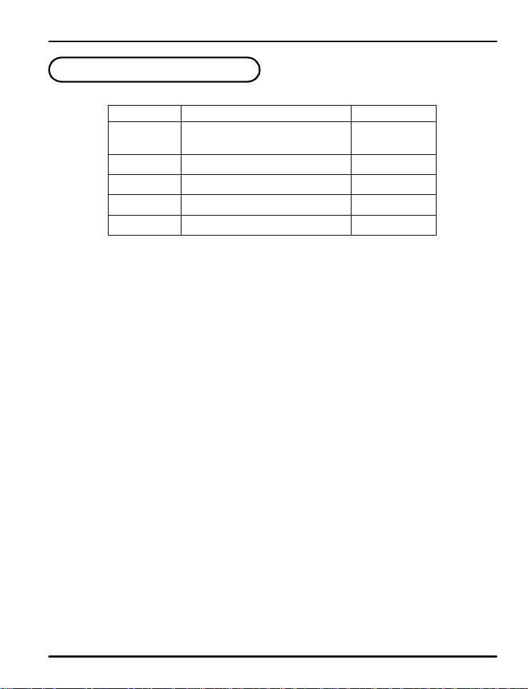
6. Error Display and Correcti o n
Error Message Action Needed
E.SY S Needs Repair
E.RJC Needs Repair
SP Decimal
Flashing
S.OPN Ch eck Se ns or
E.AT Check Process
Auto-Tune Timed Ou t (Over 2 4 H o u r s )
Error In c i dent
EEPROM, Data Loss
RJC Sensor Failure
Communication Failure
Open Sensor Detected
Check Comm Cable
39
Page 40
PD540 Series Nova Digital Process and Temperature Controller Instruction Manual
7. Installation
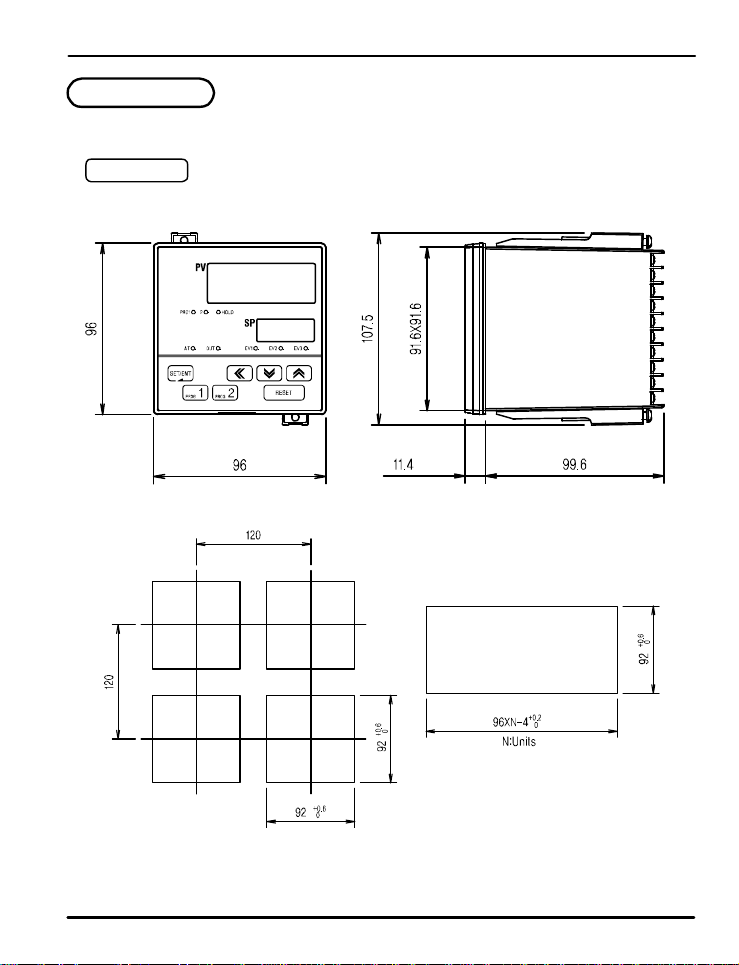
7.1 Dimensions and Panel Cutouts
PD548-PD549
1/4 DIN
(3.78)
(3.78) (0.45)
(4.72)
(4.72)
(3.62)
(4.23)
(3.61x3.61)
(3.92)
(3.62)
(3. 62)
Units:
(3.78XN)
m
m
(inch) - for reference on ly
40
Page 41
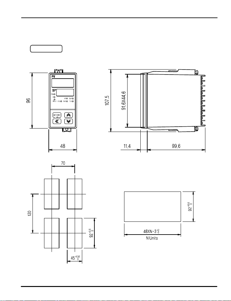
PD540 Series Nova Digital Process and Temperature Controller Instruction Manual
PD546-PD547
1/8 (V) DIN
(3.78)
(4.72)
(1.89)
(2.76)
(1.77)
(4.23)
(3.61X1.76)
(0.45) (3.92)
(3.62)
(3.62)
(1.89XN)
m
Units: m
(inch) - for reference on ly
41
Page 42
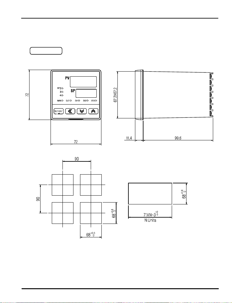
PD540 Series Nova Digital Process and Temperature Controller Instruction Manual
PD544-PD545
3/16 DIN
(2.83)
(2.83)
(3.54)
(3.54)
(2.68)
(2.65X2.65)
(0.45) (3.92)
(2.68)
(2.80XN)
m
Units: m
(2.68)
(inch) - for reference on ly
42
Page 43
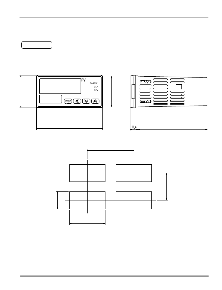
PD540 Series Nova Digital Process and Temperature Controller Instruction Manual
PD542-PD543
1/8 (H) DIN
48
(1.89)
44.6X91.6
(1.76X3.61)
96
(3.78)
(0.45)
99.6
(3.92)
120
(4.72)
70
(2.76)
0
+0.6
45
(1.77)
+0.6
92
0
(3.62)
m
Units: m
(inch) - for reference on ly
43
Page 44
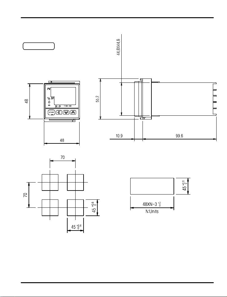
PD540 Series Nova Digital Process and Temperature Controller Instruction Manual
PD540-PD541
1/16 DIN
(1. 76X1.76)
(1.89)
(2.76)
(1.89)
(2.76)
(1.77)
(2.17)
(0.43) (3.92)
(1.77)
(1.89XN)
m
Units: m
(inch) - for reference on ly
(1.77)
44
Page 45
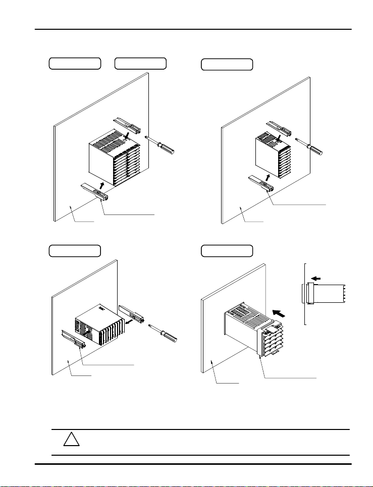
PD540 Series Nova Digital Process and Temperature Controller Instruction Manual
7.2 Panel Mountin g
PD548-PD549 PD544-PD545
PD546-PD547
Mount ing Br ack et
Panel
PD542-PD543
Mo unt ing Bra cket
Panel
Installation Steps
1. Cut the mounting panel. (Refer to 7.1 Dimen s io n s a nd Panel Cutouts)
2 . Insert the controller through the front o f t h e p a n e l r e a r t e rminals f irst.
3. On applicable models, attach the right and left mounting bracket and secure it to the panel.
4. On 1/16 DIN controller models, slide the mounting bracket onto the back of the controller as shown, and slide it
forward on the contr o l le r unti l t h e b racke t lo cks in p lace , and the controller is secure.
Do not excessively tighten the mounting bracket screws. Excessive tightening may lead to
!
CAUTION
controller or p anel damage.
PD540-PD541
Panel
45
M o unting Br acket
Panel
Mounting Bracket
Page 46
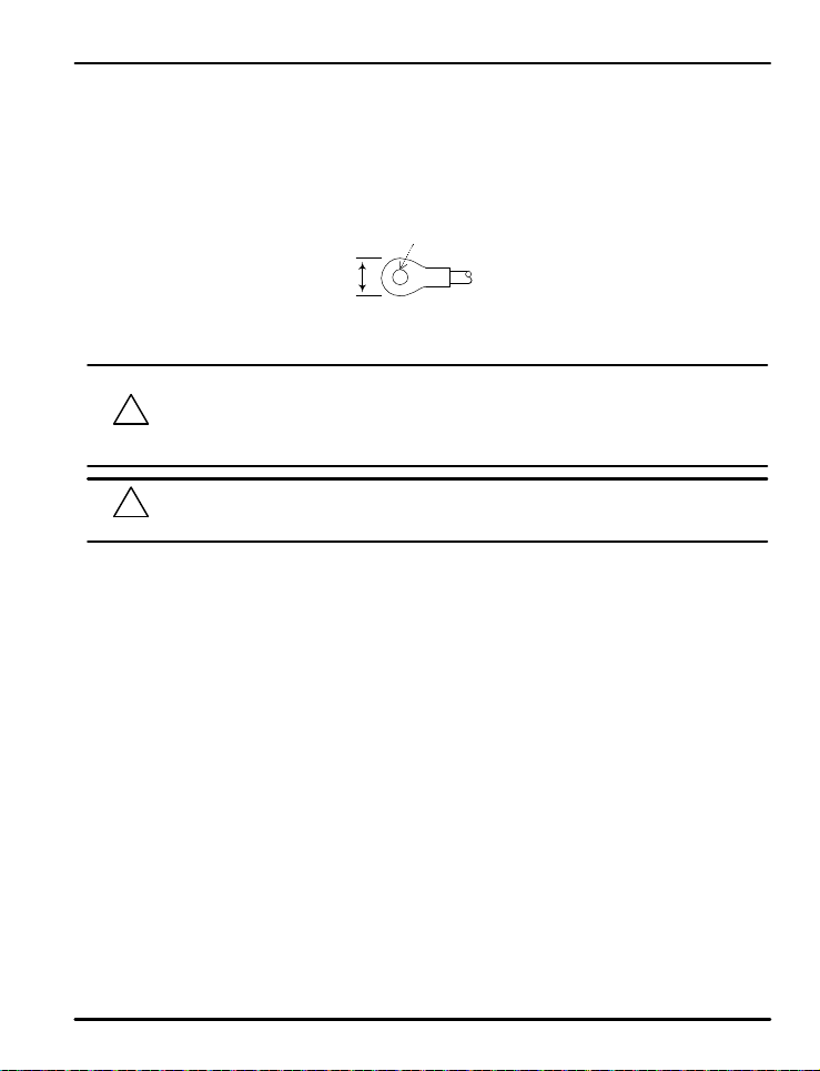
PD540 Series Nova Digital Process and Temperature Controller Instruction Manual
7.3 Power Cable Specification
Make power connections using 0.9 to 2.0 mm2 or 1 6 A WG vinyl insu l a t e d wire. (Voltage rat i n g o f 300 VAC)
7.4 Terminal Specification
Use M3.5 scr e w- c o mp a t ib l e cr i mp o n t e r min a l s wi t h in s u la t i n g sl e e ve as shown b e lo w.
Maxi mu m
Measurement
Use copper conductors only if the terminal is for connection to copper wire only.
Always turn off t h e so u r c e ci r c u it b reake r a n d c h e ck t o e n su r e t h e p o we r is of f t o t h e c o n t r o l le r thr o ugh the
use of a tester pr i o r t o wo r k i n g o n t h e wi r i n g t e r min a l s.
!
CAUTION
!
CAUTION
z Never touch the terminals in the rear panel when power is supplied to the controller.
z Be sure to tu r n o f f th e electric po wer before wiring an y t e rminal s.
Bind the wires conne ct e d t o t h e co n t rolle r t e r mi n a ls se c u r e l y t ogether in order to
prevent el e ct r o ma g n e t i c i n t e r f e r e n c e .
5.8 m m
(0.228 in)
Minimum Diameter
3.0 mm
(0.118 in )
Note: Inch e s f o r ref e r e n c e o n l y.
46
Page 47
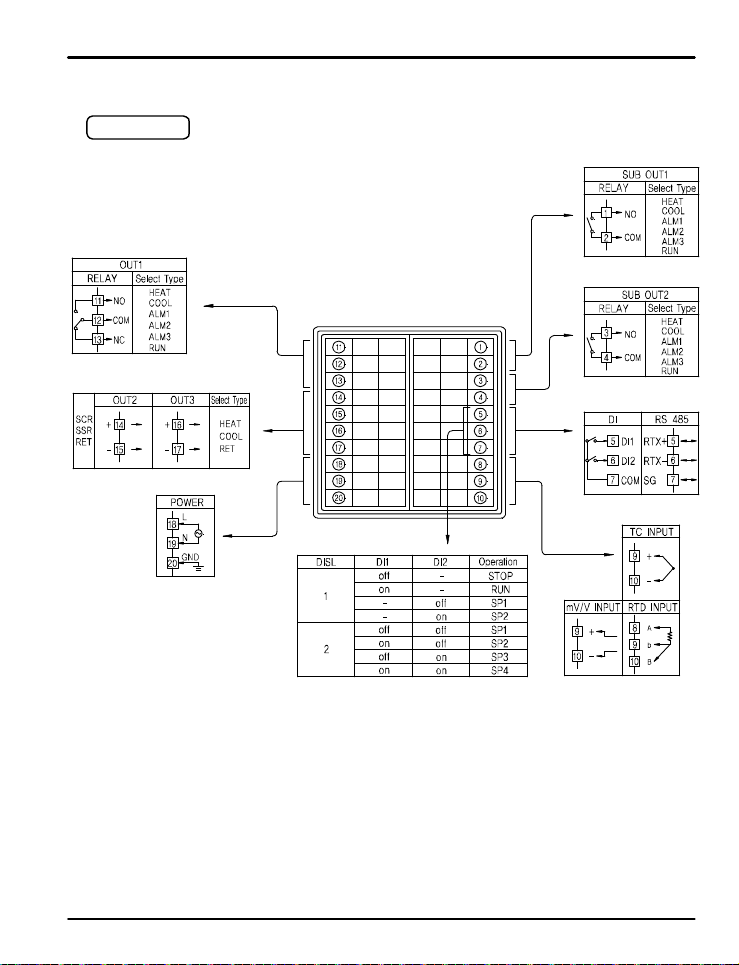
PD540 Series Nova Digital Process and Temperature Controller Instruction Manual
7.5 Terminal Assignment, Connec t ion s, and Rating s
PD548-PD549
Rating: 250 VAC @ 3 A
30 VDC @ 3 A
4 - 20 mADC or 15 VDC Voltage Pulse
100 - 240 VAC 50/60 Hz
Open circuit voltage:
approximat e ly 5 VD C
Lo = 0 to 0.8 VDC
Hi = 4.7 t o 28 VD C
NO switches (external excitation not required) or open collector transistor
Logic le v e ls :
Rating: 250 VAC @ 1 A
30 VDC @ 1 A
Rating: 250 VAC @ 1 A
30 VDC @ 1 A
-
Max: 19200 b p s
47
Page 48
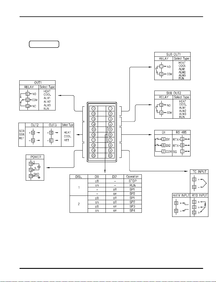
PD540 Series Nova Digital Process and Temperature Controller Instruction Manual
PD546-PD547
Rating: 250 VAC @ 3 A
30 VDC @ 3 A
4 - 20 mADC or 15 VDC Voltage Pulse
100 - 240 VAC 50/60 Hz
Rating: 25 0 VA C @ 1 A
Rating: 25 0 VA C @ 1 A
Open circuit voltage:
approximat e ly 5 VD C
Logic le v e ls :
Lo = 0 to 0.8 VDC
Hi = 4.7 t o 28 VD C
30 VDC @ 1 A
30 VDC @ 1 A
-
Max: 19200 b p s
NO switches (external excitation not required) or open collector transistor
48
Page 49
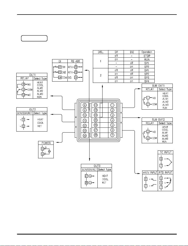
PD540 Series Nova Digital Process and Temperature Controller Instruction Manual
PD544-PD545
Rating: 250 VAC @ 3 A
30 VDC @ 3 A
4 - 20 mADC or
15 VDC Voltage Pulse
100 - 240 VAC 50/60 Hz
NO switches (external excitation not required) or open collector transistor
Open circuit voltage:
approximat e ly 5 VD C
-
Logic le v e ls :
Lo = 0 to 0.8 VDC
Hi = 4.7 t o 28 VD C
Rating: 25 0 VA C @ 1 A
30 VDC @ 1 A
Rating: 25 0 VA C @ 1 A
30 VDC @ 1 A
Max: 19200 b p s
49
Page 50
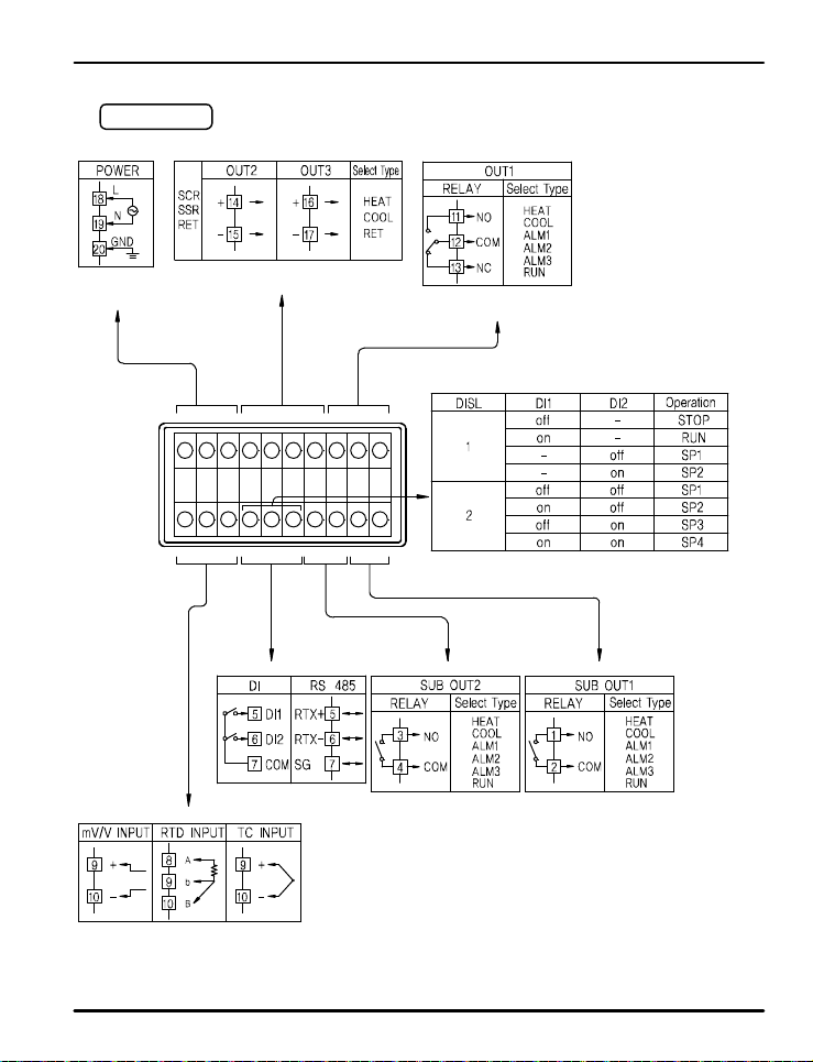
PD540 Series Nova Digital Process and Temperature Controller Instruction Manual
PD542-PD543
100 - 240 VAC
50/60 Hz
4 - 20 mADC or
15 VDC Voltage Pulse
20
19 18 17 16 15 14 13 12 11
10987654321
-
Max: 19200 b p s
Rating: 250 VAC @ 3 A
30 VDC @ 3 A
NO switches (exter n a l e xcitatio n n o t r equired)
or open collector transistor
Rating: 250 VAC @ 1 A
30 VDC @ 1 A
Rating: 250 VAC @ 1 A
Open circuit voltage:
approximat e ly 5 VD C
Lo = 0 to 0.8 VDC
Hi = 4.7 t o 28 VD C
30 VDC @ 1 A
Logic le v e ls :
50
Page 51
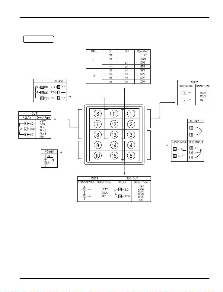
PD540 Series Nova Digital Process and Temperature Controller Instruction Manual
PD540-PD541
NO switches (external excitation not required) or open collector transistor
Open circuit voltage:
approximat e ly 5 VD C
Logic le v e ls :
Lo = 0 to 0.8 VDC
Hi = 4.7 t o 28 VD C
-
Max: 19200 b p s
Rating: 250 VAC @ 3 A
30 VDC @ 3 A
100 - 240 VAC 50/60 Hz
Rating: 25 0 VA C @ 1 A
30 VDC @ 1 A
4 - 20 mADC or
15 VDC Voltage Pulse
Rating: 250 VAC @ 1 A
30 VDC @ 1 A
51
Page 52
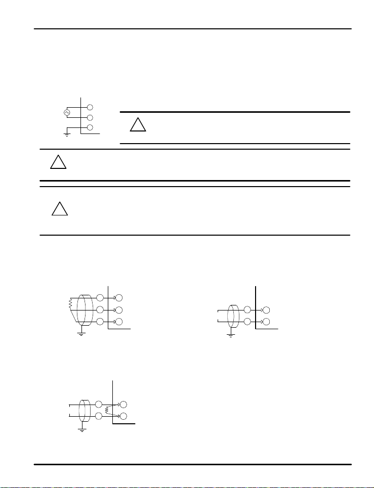
PD540 Series Nova Digital Process and Temperature Controller Instruction Manual
7.6 Grounding and Power Cable Connection
Use a thick g r ounding cable of at least 2 mm2 or 14 AWG and shorter than 20 m (approximately 22 ft) for class-3
grounding or better with a gr o u nd i n g r e s is t a n ce o f l e ss t han 100 Ω .
Be sure to ground from the grounding terminal to an independent grounding point. (1 point grounding)
Use 0.9 to 2.0 mm2 or 1 6 A WG vinyl insu l a t e d wire (Voltage rating 300VAC) or thicker for power cable connection.
!
CAUTION
!
CAUTION
7.7 Signal Inpu t Connection
(1) RTD Input (2) DC Voltage In p ut
RTD
L
N
GND
CAUTION
To prevent electric shock, b e su r e t o t u rn off p o we r to t he c o n t r o l le r and the source circuit breaker before
wiring.
Be sure to connect to correct polarities. Connecting to a wrong polarity may cause damage or malfunction.
Use shielded wires and ground the shielding to an independent grounding point.
Keep the input signal and output wiring as far as possible away from the power and ground circuit.
Use a wire with low conductive resistance and no three-wire resistance differential.
SHIELD
A
b
INPUT
B
NOVA
Be sure to connect L (Hot), N (neutral), and GND (gr ound) as indicated.
!
Failure to wire th e po we r and ground as indicated could result in damage
to the controller.
SHIELD
+
V
INPUT
NOVA
(3) DC Current I np ut
SHIELD
DCmA
To accept a 4-20 mA s ignal, select 0.4 to 2.0 VDC input and
connect a 100 Ω resistor across th e i nput terminals as shown.
+
R
-
INPUT
NOVA
52
Page 53
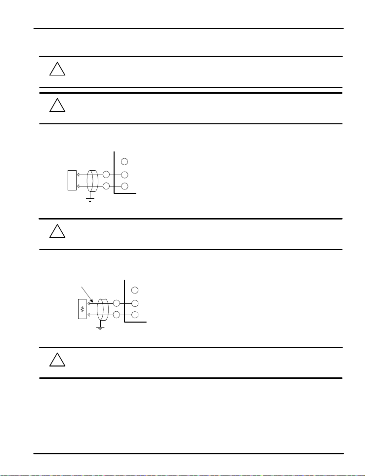
PD540 Series Nova Digital Process and Temperature Controller Instruction Manual
7.8 Analog Outp ut Connec t ion
To prevent electric shock, b e su r e t o t u rn off p o we r to t he Nov a C o n t r o l le r and the source circuit breaker
!
CAUTION
CAUTION
(1) Voltage Pulse Output (SSR) / C u r r e n t Output (SCR)
Control
Device
CAUTION
(2) Retransmitti n g Output (RE T)
4 to 20 mADC, 600 Ω max
or 14-18 VDC @ 20 mA max
Receiver
(Recorder, et c )
before wir i n g .
Be sure to connect to correct polaritie s . Conn e ct i n g t o a wr o n g pola r i t y ma y cause a cont r o ll e r ma l f u n ct i o n .
!
Use shie ld e d wir e s for t h e wiring and c o n n e ct independently to ground (1 point grounding).
SCR : 4 to 20 mADC, 600 Ω maxi mum
SHIELD
+
OUT2,3 +
-
OUT2,3 -
NOVA
To prevent electric shock, b e su r e t o t u rn off p o we r to t h e Nov a C o n t r o l le r and t he s o u r c e ci r c u it b reake r
!
before wir i n g .
SHIELD
+
RET+
-
RET-
NOVA
SSR : 12 VDC min, 600 Ω minimu m
!
CAUTION
To prevent electric shock, b e su r e t o t u rn off p o we r to t he Nov a C o n t r o l le r and the source circuit breaker
before wir i n g .
53
Page 54
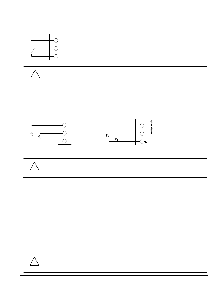
PD540 Series Nova Digital Process and Temperature Controller Instruction Manual
7.9 Relay Output Connection (RELAY)
!
CAUTION
7.10 Digital Input Connection (DI)
Use a no-voltage contact switch such as relay.
The controller supplies the needed voltage (approx . 5 VDC) and current ( approx. 1 mA) to trigger the input.
Whe n using an Open Collector (TR) as a trigger, use one with a 2 V or lower vo l t a g e rating when "on " a n d
100 μA or less leakage current w hen it is OFF.
Relay Contact Connection
!
CAUTION
7.11 Use of an External Relay
Switching Inductive Loads
When using switching in ductive loa d s , t h e u se o f R C n e t wo rks (snubber s) for AC loads or diodes for DC loads is
recommended to prevent disrupting the microprocessor's operation. The suppressors also prolong the life of the
relay contacts. Suppression can be obtained with resistor-capacitor (RC) networks or diodes assembled by the
user or purchased as complete assemblies.
For AC loads, choose R and C as follows:
R: 0.5 to 1 Ω for each volt across the contact
C: 0.5 to 1 μF for each amp through closed contacts
Notes:
1 . Use capacitor s rated f o r 250 VAC.
2. RC networks may affect load release time of solenoid loads. Check to confirm proper operation.
3 . RC networks are availa b l e f r o m P r e c is io n D i g it a l and should be applied to each relay contact switching an
inductive load. Part number: PDX6901.
Relay: NO - Normal l y Open Conne c t io n
COM
Relay: NC - Normal ly Clos e d C o n n e ct i o n
NOVA
To prevent electric shock, b e su r e t o t u rn off p o we r to t h e Nov a C o n t r o l le r and the source circuit breaker
before wir i n g .
DI_1
DI_2
DI_COM
NOVA
To prevent electric shock, b e su r e t o t u rn off p o we r to t h e Nov a C o n t r o l le r and the source circuit breaker
before wir i n g .
Transistor Cont a c t C onnection
+5V
DI_1
DI_2
DI_COM
NOVA
!
CAUTION
If the load inductance is over the controller specifications, the output may need a R C filter (snubber) or
diode to properly handle frequent relay switching operations.
54
Page 55
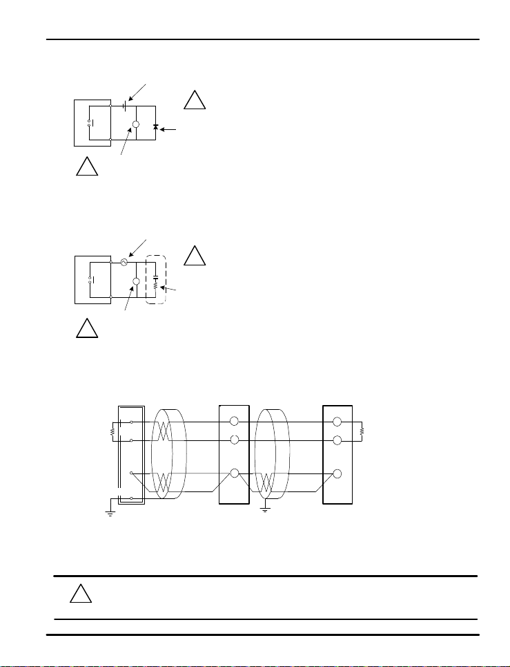
PD540 Series Nova Digital Process and Temperature Controller Instruction Manual
(1) DC External Relay
Controller
!
CAUTION
(2) AC External Relay
Controller
!
CAUTION
External DC
power
R
Relay
(Verify relay coil ratings are l e s s t h a n t h e voltage a n d c u r rent ratin g s o f t h e relay
contacts of th e c o n t r o l le r)
External AC
Powe r
R
Relay
(Verify relay coil ratings are l e s s t h a n t h e voltage and curr ent ratings of the relay
contacts of th e c o n t r o l le r)
7.12 Communication Wiring (RS-485)
Master Station NOVA Controll e r
RTX+
Terminatin g Resisto r
RTX- RTX- RTX-
SG
!
CAUTION
Diode
(Connect directly to the relay coil t e r mi n a ls )
!
CAUTION
RC Network (snubber)
(Connect directly to t h e relay c o i l t e r mi n a ls )
RTX+
SG
NOVA Controll e r
RTX+
Terminatin g Resisto r
SG
SHIELD
Up to 31 slave controllers ( N o va series controllers equipped with the RS-485 serial communication
option) can be connected.
Be sure to connect terminating resistors (22 0 Ω, 1/4 W) t o sl a ve and ma st e r controlle r s at
communication channel ends as shown above.
To prevent electric shock, b e su r e t o t u rn off p o we r to t h e Nov a C o n t r o l le r and the source circuit
!
CAUTION
breaker be f o re wiri n g .
55
Page 56
PD540 Series Nova Digital Process and Temperature Controller Instruction Manual
Table of D-Registers:
The following data re g i st e r s a r e u s e d t o d irect t h e U S 1 an d U S 2 c o mmands or for Modbus communication.
NO.
PROC_TIME20
30
PROCESS FUNCTION SET POINT SIGNAL ALARM PID IN/OUT
0 100 200 300 400 500 600
SPSL0
R-S,STOP/RUN
NPV
SP1 ALT1 ARW IN-T1
NSP SP2 ALT2 FUZZY INT-U2
SP3 ALT3 C.MOD IN.RH3
SP4 IN.RL4
SPSL A/M IN.DP5
HOUT
H.OUT(MVOUT)
C.OUT(MVOUTc)
AL-1 IN.SH6
AL-2 IN.SL7
MVOUT
COUT AL-3 IN.FL8
PIDNO BSL9
NOWSTS RSL10
SPRH A1DB 1.P BSP111
SPRL A2DB 1.I BSP212
A3DB 1.D BSP313
ALSTS TMU 1.MR14
1.Pc BS015
U.SLP A1DY 1.Ic BS116
D.SLP A2DY 1.Dc BS217
A3DY 1.DB BS318
ERROR RP1 BS419
AT AL1.H 2.P OUT121
AT-G AL2.H 2.I OUT222
AL3.H 2.D OUT323
2.MR24
2.Pc SUB125
AL1.L 2.Ic SUB226
AL2.L 2.Dc27
AL3.L 2.DB28
RP229
S-TM 3.P HEAT231
P-TM 3.I COOL232
3.D HEAT333
ONOF 3.MR COOL334
US1 3.Pc35
US2 3.Ic37
LOCK 3.Dc O.ACT36
DI. SL 3.DB CT38
DSP.H RHY CTc39
DSP.L40
4.P OH41
4.I OL42
4.D43
56
Page 57
PD540 Series Nova Digital Process and Temperature Controller Instruction Manual
NO.
50
57
62
63
64
65
66
67
68
69
70
71
72
73
74
75
76
77
78
79
80
81
82
83
84
85
86
87
PROCESS FUNCTION SET POINT SIGNAL ALARM PID IN/OUT
0 100 200 300 400 500 600
U RETL53
s54
e55
r56
A58
r59
e60
a61
4.MR HYS44
4.Pc45
4.Ic PO46
4.Dc POc47
4.DB HYS.H48
RDV HYS.L49
RET51
RETH52
COM.P
BAUD
PRTY
SBIT
DLEN
ADDR
RP.TM
57
Page 58
PD540 Series Nova Digital Process and Temperature Controller Instruction Manual
NO.
88
89
90
91
92
93
94
95
96
97
98
99
PROCESS FUNCTION SET POINT SIGNAL ALARM PID IN/OUT
0 100 200 300 400 500 600
?
NOTE
Read Only Location
58
Page 59

PD540 Series Nova Digital Process and Temperature Controller Instruction Manual
?
NOTE
Notes
Warranty and Retu rn I n f orm a t i o n
Precision Digita l wa r rants t h is p r o d u c t t o b e f ree f r o m mat e rial d e f e ct s and workmanship under normal use and
service fo r t h ree y e a r s .
Please contact Precision Digita l Technical Su p p o rt at (800) 610-5239 or e-mail at [email protected] prior to
any product return. When Technical Support determines a product should be returned, a Return Material
Authorization (RMA) # whic h mus t b e in c luded on the r eturn shipping label. Please also include the reason for
return, da t e o f p u r c ha s e , co n t a c t n a me , an d h o w t o c o n t a ct . P r o d u c t s returned f o r rea s on s o t h e r t han r epair may
be subject to a restock i ng f e e . A n y ret u r n s u nd e r a war r a n t y claim s h o ul d b e r e t u rned f reigh t p r epaid. Upon
warranty confirmation Precision Digital will repair o r r e place and return the unit at no charge via UPS Ground.
Other shipping is ava il a b le u p o n request and at customer expense. All product returns should be shipped to:
Return Authorization # ___________
Precision Digital, 89 October Hill Road Ste 5, H ollist on, MA 01746 USA
Attention: Technical Support
Precision Digital Technical Support is trained and eager to serve y ou. We have found most start-up problems to
be the result of incorrect signal connectio n s a n d / o r pro g r a mmin g . M o s t o f t e n P recisi o n Digit a l Technical
Support ca n q u ic kl y c o r rect t h e se i ss u e s o ver the t e lephone.
59
Page 60

PD540 Series Nova Digital Process and Temperature Controller Instruction Manual
How to Contact Precision Digital
z
z
z
For Technical Support
Call: (800) 610-5239 or (508) 655-7300
Fax: (508) 655-8990
Email: [email protected]
For Sales Support o r t o p la c e a n o r de r p le a s e
Call: (800) 343-1001 or (508) 655-7300
Fax: (508) 655-8990
Email: [email protected]
For the latest version of this manual, please visit
www.predig.com
LIM540_C
06/0 9
 Loading...