

Page 1
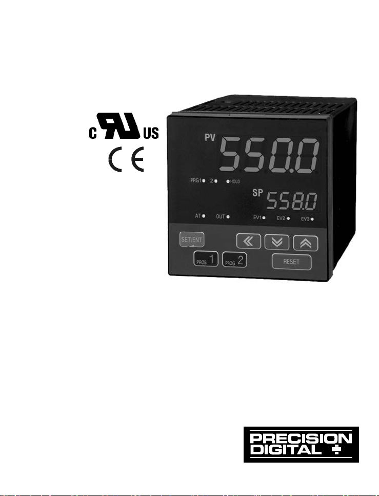
PROGRAMMABLE
RAMP & SOAK CONTROLLER
®
NOVA PD550 Series
Instruction Manual
PD550 - PD558
PRECISION DIGITAL CORPORATION
89 October Hill Road
Tel (800) 343-1001
z
Holliston MA 01746 USA
z
Fax (508) 655-8990
Page 2
PD550 Series Nova Programmable Process and Temperature Controller Instruction Manual
Disclaimer
The information contai ned i n t h i s documen t i s subjec t t o c h an ge wi t h out n oti ce.
Precision D i g i t al C or p or ati on m akes no repres en t ati ons or warran t ies with
res p ect t o t h e contents hereof , and s pecifically di scl aims an y impli ed warr an t ies
of merchantability or fitness f or a particular purpose.
Registered Trademarks
MODBUS® is a registered tr ademar k of Schnei der A u t omat i on I n c. All ot h er
trademarks men t ion ed i n t hi s docum ent ar e th e p r oper t y of t h eir respect i ve
owners.
Visit our Web S i te
http://www.predig.com
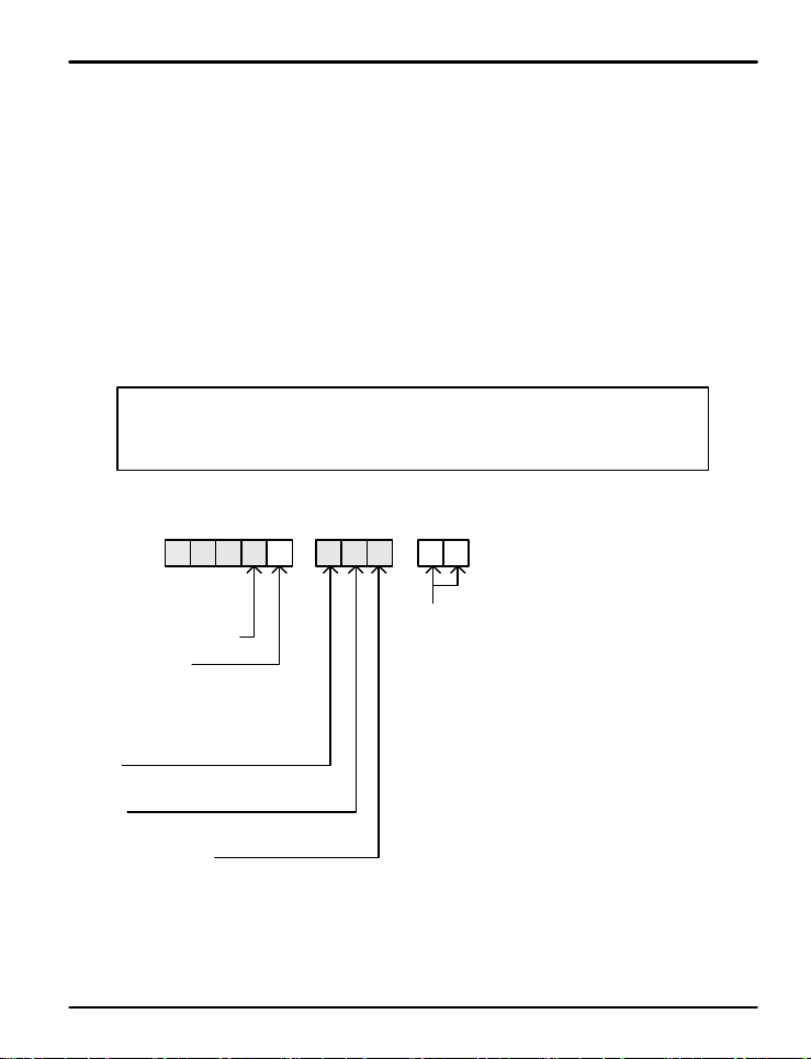
Nova PD550 Series Model Number Guide
0-6RA-00PD5 5
Programmable
Ramp & Soak Controller
Size - DIN Cutou t
0 = 1/16 DI N
4 = 3/16 DI N
6 = 1/8 DIN ( V)
8 = 1/4 D I N
Power
6 = 100-240 VAC
Display
R = Red LED
Main Control Ou tp u t
PD540, PD554:
A = 1 relay & 1 analog output
PD556, PD558:
B = 1 relay & 2 analog outputs
Options
00 = None
PD550:
02 = 2 digital outputs
03 = 4 digital outputs
11 = 1 relay & 2 digital inputs
14 = 1 relay & RS-485
31 = 1 analog output & 2 digital input s
34 = 1 analog output & RS-485
PD554:
02 = 2 digital outputs
03 = 4 digital outputs
04 = RS-485
51 = 2 relays, 1 analog output & 2 digit al input s
52 = 2 relays, 1 analog out put & 2 digital out puts
53 = 2 relays, 1 analog out put & 4 digital out puts
54 = 2 relays, 1 analog output & RS-485
PD556 & PD 558:
21 = 2 relays & 2 digital inputs
24 = 2 relays & RS-48 5
25 = 2 relays & digital inputs
26 = 2 relays, RS-485 & 4 digital output s
©2009 Precision Digital C or p orat i on. A l l r i g h t s reserved.
2
Page 3

PD550 Series Nova Programmable Process and Temperature Controller Instruction Manual
Table of Contents
1. Safety Guide and Specifications 5
1.1 Specifications
2. Front Panel Buttons and LED Indicators 11
7
3. Parameter Map
12
4. Operation Flow Chart 14
5. Parameter Setup
5.1 Input Group ( G.IN )
5.2 Output Group (G.OUT)
5.3 Control Group (G.CTL)
5.4 Program Group (G. PROG)
5.5 Digital Output Group (G.D O ) 30
5.6 Inner Signal Group (G.IS)
5.7 PID Group ( G . PID)
5.8 Auto-Tuning Group (G.AT)
5.9 Alarm Group (G.ALM)
5.10 Retransmission Group (G.R E T )
5.11 Communication Group (G.COM)
6. Error Display and Correction
7. Installation
7.1 Dimensions and Pane l Cut outs
7.2 Panel Mounting
7.3 Power Cable Specifications
7.4 Terminal Specifications
7.5 Terminal Assignment, Connections, and Ratings
15
15
19
22
24
31
33
35
37
40
41
43
44
44
48
49
49
50
3
Page 4

PD550 Series Nova Programmable Process and Temperature Controller Instruction Manual
7.6 Grounding and Power Cable Connection
7.7 Signal Input Connection
7.8 Analog Output Conn ection
7.9 Relay Output Connection (RELAY)
7.10 Digital Input Connection (DI)
7.11 Use of an Externa l Relay
7.12 Communication Wiring (RS-485)
Appendix
Table of D-Registers
Tables and Figures
Table 1: Universal Input Selection
Table 2: DI Operation
Table 3: Link Codes
Table 4: DO Settings and Functions
Table 5: Alarm Selection
Fig 1: Temperature Bias
Fig 2: Bias Formula Calculation
Fig 3: Time-Proportional PID Control Output
Fig 4: Start Code SSP Start
Fig 5: Wait Function Wait Zone Release
Fig 6: Wait Function Wait Time Release
Fig 7: Inner Signal Zones
Fig 8: Overshoot Suppression with Fuzzy L og ic
Fi g 9: Auto-Tuning
Fig 10: Auto-Tuning Gain
Fig 11: Alarm Operation
54
54
55
56
56
56
57
58
15
22
27
30
38
17
17
20
24
26
27
31
33
35
36
38
4
Page 5
PD550 Series Nova Programmable Process and Temperature Controller Instruction Manual
1. Safety Guide and Speci f icat i ons
The following safety symbols are used in this manual
(1) This symbol notifies the us e r o f s p e ci f ic i nf o rmatio n r e l a t in g t o t h e s a f e o pe ratio n o f t h e c on t rolle r .
!
CAUTION
?
NOTE
&
!
CAUTION
!
CAUTION
Information noted with this symbol must be observed to protect the user from injury and to prevent dama g e
to the product.
(A) For User: Be awa re of t h i s ma rking i n t h e ma n u al a n d r e f e r to th e e xplanat io n i n t h e manua l to
(2) For Installer : Stud y the warning s marked t o p r e vent inju ry and dama g e .
(2) Functional ea rth te rminal : This symbol i n d ic a t e s t h a t t h e t e r mi n a l mu st b e c onnected to ground.
(3) This symb o l in d i ca t e s a d d it i o n a l i n f o r ma t io n o n t h e f e a t u r e s o f t h e p r oduct.
(4) This symbol directs the r e a d e r to further info r ma t i o n o n t h e cu r rent t o pi c .
Precautions R eg a rd i ng T his Instr ucti o n Man u al
(1) This manual must be kept in the possession of the end user and in a suitable place for the operator to
study and to check the functions of the product.
(2)The installer and operator should carefully study and understand how to operate this product before use.
(3)This manual describes the functions of the product. Precision Digital Corpo r a t i o n d o e s n o t guarantee
that the functions will suit a particu lar pu r pose .
(4) The contents of this manual have been r eviewed for accuracy and correctness. However, should a n y
errors or omission s c o me t o t h e at t e n t i o n o f t h e u se r, con t a ct t e c h n ic a l s upport as listed on the back of this
manual
Safety Procedures and Unauthorized Modification Warning
(1)In order to prot e c t t h i s p r oduct and the system controlled by it against damage and ensure its safe use,
make certain t h a t a ll o f t h e sa f e t y inst r u c t io n s a n d precau t i o n s i n t h is manual are strictly adhered to.
(2)Precision Digital Co r p o r a t i o n d o e s not gua r a n t e e sa f e t y if th e p roduc t s a re not h andled in accordance
with this instruction manual.
(3) If separate prot ec t i o n o r safe t y circ u it s a r e t o b e in s t a ll e d in t h e s y s t e m wh ic h is co n t rolle d b y t h i s p r oduct,
ensure that such cir c u it s a r e i n st a l le d e xternal t o t h i s p r oduct.
(4) Do not make modifications or additions internally to the product. It may cause personal injur y t o t h e u s e r o r
damage to the product.
(5)Contact tec h n ic a l s u p p o r t a s li st e d o n t h e b a ck o f t h e manual for warranty and r epair issues.
(6)Exposure t o e xcessiv e moi s t ure, e le c t r i ca l o verloads, or mechanical vibration may damage the product.
prevent injury and damage.
!
CAUTION
Limited Liability
Precision Digital Corpo ratio n a ss u mes n o li a b ility t o a ny pa r ty f or an y loss o r d amage , dir e ct o r in dir ect ,
caused by the use of or any unpredictable defect of the product.
5
Page 6

PD550 Series Nova Programmable Process and Temperature Controller Instruction Manual
Operational Enviro nment Precautions
!
CAUTION
CAUTION
(1)Only operate th e c o n t r o l le r when i t is p r o p e rly in s t a ll e d .
(2)When installing the controller, select a location where:
Rear terminal s a re pr o t e ct e d f r o m a c ci dental contact.
Mechanic a l vibrati o n s a re minima l .
No corrosive ga s i s p resen t .
Temperature fluctuation is minimal.
Temperature can be maintained between 10 and 50 ºC (50 and 110º F ) with 2 0 t o 9 0 % R H .
No direct heat radiation is present.
High levels of electromagnetic interference are not present
The unit is not exposed to water.
No flammable materials are present.
Dust particles are n o t p r e s e n t in t h e a i r .
Exposure t o u lt rav i o le t rays is min i mal .
Openings on th e rear o f t h e co n t r o l le r are n o t b lo c ke d .
(3)This unit is suitable f o r i n st a l l a t io n i n a n e n viornmen t c la s si f ie d a s Pollution D e g r e e 2 .
(4)This unit is designated as Installation Category II .
(5) If the equipment is used in a manner not specified by the manufacturer, the protection provided by
the equipment may be impai red.
(6)A switch or circuit -break e r a c t in g a s t h e d is connect dev ice shall be included in the application or the
installation.
Controller Mounting Precautions
!
Keep the input circuit wiring as far a s poss i b le away from p o wer and grou n d circuits.
Keep the un i t s in 1 0 t o 5 0 º C (50 to 1 1 0 º F) with 20% to 90% relat i ve humidit y (RH) .
The controlle r may n e e d a wa r m u p p e r i o d t o retu r n t o o p e r a t i n g t e mpe rature ra nges when below 10ºC.
To prevent electric shoc k , b e s u r e t o t u rn off t h e p o we r sour c e a n d ci r c u it b r e a k e r b e f o re wiri n g .
The powe r req u irement s are 100 t o 240 VAC, 50/60 Hz , 10 VA max. Do not switch power
supplies without first disconnecting the power supply.
Follow the operating procedures and precautions in the manual to avoid fire, shock, damage to the unit,
or injury. Follow the operations and mounting directions indicated in this manual.
Always create a ground connection where indicated, however do not ground to gas pipes,
water pipes, lighte n i n g r o d s , o r o t h e r p o t e n t i a ll y h a zard o u s me t a l o b je c t s.
Do not apply power to the unit until all connections have been ma d e .
Do not cove r t h e venting h o le s in t h e rear o f t h e u n it .
6
Page 7

PD550 Series Nova Programmable Process and Temperature Controller Instruction Manual
1.1 SPECIFICATIONS
Except where note d a ll sp e c i f ic a t io n s apply to operation at 23ºC.
General
DISPLAY Dual 4 digits, red LED, -1999 to 9999
DIN Sizes PV Display SP Display Weight
mm (inch) mm (inch) g (oz)
1/16 11.3 (0.45) 9.5 (0.37) 198 (7.0)
3/16 14.0 (0.55) 12.0 (0.47) 324 (11.4)
1/8 (V ) 13.6 (0.54) 10.5 (0.41) 304 (10.7)
1/4 20.5 (0.81) 11.0 (0.43) 389 (13.7)
FRONT PANEL 1/16 & 1/8 DIN: IP65; 3/16 & 1/4 DIN: IP55
SAMPLING TI ME 250 ms
OVERRANGE Ove r ran ge PV rea d s ovR, under range PV reads -ovR
PROGRAMMING Four fr on t p anel b u t t ons and Modbus
METHODS
PID ZONES 3 programmable PID zone ranges, 1 PID PV deviation zone
NOISE FILTER Programmable from 1 t o 1 2 0
CALIBRATION All ranges are c al i b rated at the factory
PASSW ORD Progra mmab le pa ss word rest ricts mo dificat ion of
programmed settin g s
POWER 100-240 VAC, 50/ 6 0 HZ, 10 Watt s
FUSE Required fuse: UL Recognized, 1 A, 250 V, slow blow
ISOLATION 2300 V input-to-output-to-power lin e;
4 kV relay output-to-input/output/power line.
PROGRAMMING 2 set point program patters of 15 segments each
CAPACITY Segment repeat and pr ogram loop fu n ctions
ENVIRONMENTAL Operating temperatu re range: 10 º C t o 5 0ºC (50 º F t o 110ºF)
Relative humid i t y: 2 0 t o 90 % n on - condensi n g
MOUNTING 1/16, 3/16, 1/8, or 1/4 D I N size c u t ou t r equ i r ed
Two panel mounting b r ac k et assembl ies provided
One one-pi ec e bracket pr ovid ed for the P D 5 5 0
WARRA NTY Thr ee years p ar t s an d la bor
7
Page 8

PD550 Series Nova Programmable Process and Temperature Controller Instruction Manual
Process and Temperatu re I nputs
TEMPERATURE DRIFT Refer to accuracy specifications below
DECIMAL POINT Up to three decimal places for process inputs :
9.999, 99.99, 999.9, or 9999
REAR JUNCTION Automatic or off sett in g s for t emp er atu r e i nputs . N o user
COMPENSATION calibration requi r ed.
OFF S ET ADJUS T MENT Four programmable input bias zones
SENSOR BREAK Open sensor indi cated by PV d i splay flashing S.OPN.
DETECTION All PID control outputs t ransmit at t h e user progr amm ed
percent of f u l l ou t pu t scale s et i n p aram eter P o.
Up or down scale, user selectable; alarm relays will follow
the up or down scale select ion.
TRANSMITTER 14 to 18 VDC @ 20 mA; availab l e at term i nals OUT2 or
SUPPLY OUT3, instead of a retr ansmitt in g anal og out p u t
UNIVERSAL IN PU T TYPE A ND A CCURACY
Temp Temp
Range (ºC) Range (ºF) Accuracy*
K1 -200 to 1370 -300 to 2500
K2 -199.9 to 999.9 0 to 2300 > 0°C : ±0.1 % FS ±1 d i g it
J -199.9 to 999.9 -300 to 2300 < 0°C : ±0.2% F S ± 1 di g i t
T -199.9 to 400.0 -300 to 75 0
B 0 to 1800 32 to 3300 > 400°C : ±0.15 % FS ±1 d ig i t
Thermocouple S 0 to 1700 32 to 3100
Input Type
RTD PtC -19.99 to 99. 9 9 -4.0 to 212.0 ±0.2% FS ± 1 d ig i t
Process 0 to 10 V
*Performance with i n recomme n d e d operating conditions (10 to 50°C, 20 to 90% RH)
**For a range scale of 0 to 100°C: +0.3°C +1 digit, and for a range scale of -100 to 100°C: +0.5°C +1 digit
R 0 to 1700 32 to 3100 ±0.15% FS ± 1 d ig i t
E -199.9 to 999. 9 -300 to 1800 > 0°C : ±0.1% F S ± 1 d ig i t
L -199.9 to 900.0 -300 to 1600 < 0°C : ±0.2% F S ± 1 di g i t
U - 199.9 to 400 . 0 -300 to 75 0
N -200 to 130 0 -300 to 2400 > 0°C : ±0.1% F S ± 1 d ig i t
W 0 to 2300 32 to 4200 ±0.2% FS ± 1 d ig i t
Platinel II 0 to 1390 32 to 2500 ±0.1% FS ± 1 d i g it
PtA -199.9 to 850.0 -300 to 1560 ±0.1% F S ±1 d i g it * *
PtB -199.9 to 500.0 -199.9 to 999.9
JPtA -199.9 to 500.0 -199.9 to 999.9 ±0.1% FS ±1 di g it * *
JPtB -150.0 to 150.0 -199.9 to 300.0
0.4 t o 2 .0 V ±0.1% FS ± 1 d i g it
1 to 5 V
-10 to 20 mV
0 to 100 mV
0.400 to 2. 0 0 0
1.000 to 5. 0 0 0
0.00 to 10.00
-10.00 to 20.00
0.0 to 100 . 0
< 400°C : ±5% FS ± 1 d ig i t
< 0°C : ±0. 2 5 % F S ± 1 d ig i t
Display range can be scaled between -1999 and 9999.
4 to 20 mA Inp ut
To accept a 4 to 20 mA signal, select 0.4 to 2.0 VDC input
and connect a 100 Ω resistor across the input terminals.
8
Page 9

PD550 Series Nova Programmable Process and Temperature Controller Instruction Manual
Relay Outputs
RATINGS Out1: 250 VAC @ 3 A or 3 0 V D C @ 3 A ( r esist ive load)
Sub1, Sub2: 250 VAC @ 1 A or 30 VD C @ 1 A (r esist ive load)
ELECTRICAL NOISE A suppressor (s nubber) s hould be connected to each
SUPPRESSION re la y conta ct switc hing inductive loads, to p revent
disru p tion t o t h e m icr op r ocessor's operation.
Recommended suppressor value: 0.1 μF/470 Ω,
250 VAC (PDX6901)
DEADBAND For alarm operati ons, 0- 100% of f ull s c ale, user selectable
HIGH OR LOW U s er may program any relay for high or low trip point
ALARM
DEVIATION ALARM U ser may progr am any r elay f or a h ig h , l ow, or ran ge set
point deivation alarm.
RELAY OPERATION An y r e l ay m ay b e set as an al arm rel a y or for ti me
proportional PID control
TIME DELAY 0 to 99 minutes 59 seconds alarm trip delay user
selectable for each alarm. Ti m e p roport i on al PID control
relay acti vati on t i me d elay of 0 t o 99 mi n u t es 5 9 s econds
user selectable.
FAIL-SAFE Programmable
OPERATION Independent for each alarm relay
AUTO INITIALIZATION When power is applied to the controller, alarm relays will
reflect the state of the input to the controller except
standby alarms.
Analog Outputs
OUTPUT RANGE Continuous PID or retransmitting: 4-20 mA (600 W maximum)
Time Proportional PID: 15 VDC pulse (600 W minimum,
current limited at 3 0 mA) high , l es s than 0. 1 V D C low, cycle
time 1 to 300 seconds, user selectable
SCALING RANGE Retransmitting 4-20 mA out p u t s can be s caled for any
display range low and high
ACCURACY +0.1% of full s cale
9
Page 10

PD550 Series Nova Programmable Process and Temperature Controller Instruction Manual
Digital Inputs
CONFIGURATION Two c on tacts, t wo op erat ing m o des
CONTACTS Nor m al l y op en swi t ches (external excitati on n ot required)
or open collector transis tor
OPE N CIRCUIT A pp roximat ely 5 VDC
VOLTAGE
LOGIC LEVELS LO = 0 to 0.8 VDC, HI = 4.7 to 28 VDC
OPERATION Mode 1: Prog r am h old and step
Mode 2: P r ogram run or r es et
Digital Outputs
CONFIGURATION 2 or 4 open collector transistor
OPERATION MODES Alarms, inner signal PV or SP zones, program segmen t time
signals, SP stat u s (ramp up /d own or s oak) , p r og r am r u n or
end al er ts
TRANSISTOR RATING 24 VDC @ 50 mA
Serial Communications
PROTOCOLS Modbus (ASCII, RTU), PC software,
SYNC (master SP cont r ol )
UNIT ADDRESS 1 to 99 (Max 31 units connected)
BAUD RATE 600, 1200, 2400, 4800, 9600, 19200 bps, user selectable
RESPONSE TIME 0 to 100 ms delay response time
10 ms inc rement s us er selec table
DATA 7 or 8 bit user selectable
PARITY None, even, or odd
Approvals
UL R E C OGN IZED USA and Canada
Process Control Equipment
UL F I L E N UMBER E244207
CE COMP L I A N T
10
Page 11
PD550 Series Nova Programmable Process and Temperature Controller Instruction Manual
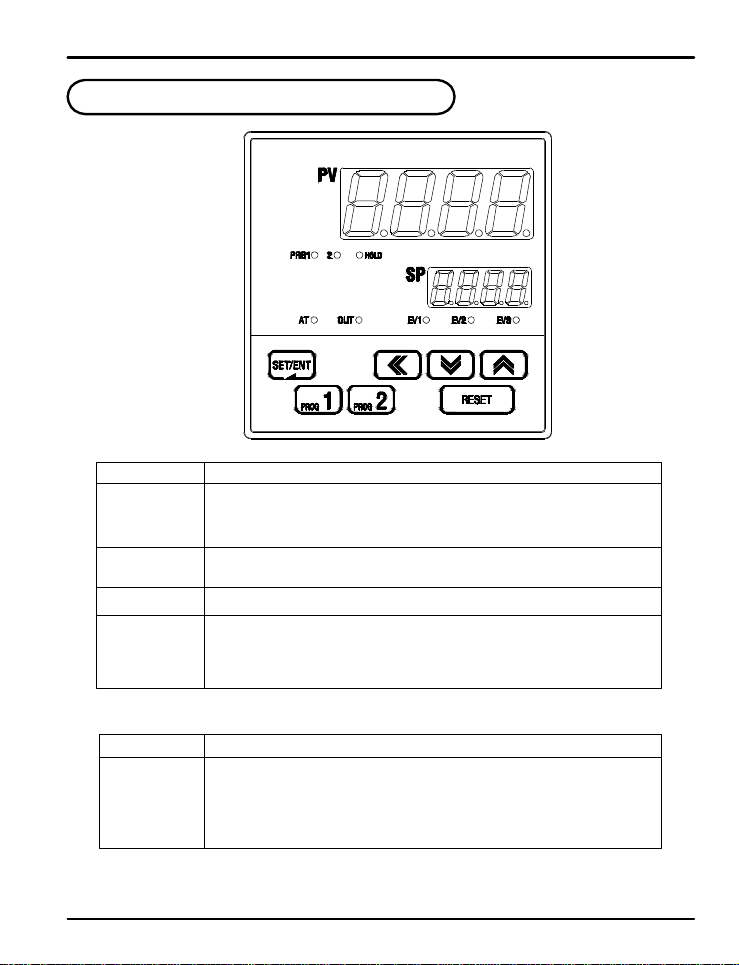
2. Front Panel Buttons and LED Indicato rs
Control K ey s
KEY Function
SET/ENT
(ENTER)
S / T
(UP/DOWN)
W (SHIFT)
PROG1 (P1 )
PROG2 (P2 )
RESET (RST)
Pressing SET/ EN T key for at le a s t 3 s e c onds switches between the operating display and
the parameter s e t t i ng d i sp l a y. T h is ke y is use d t o verify and by pass parameter settings
when in the parameter group display.
Used to change t h e value of d i g it s when setting parameters.
Used to move between parameter groups.
Used to move to the next digit when setting parameters.
Pressing program butto n 1 f o r 1 se c ond runs progr am 1.
Pressing program butto n 2 f o r 1 se c ond runs progr am 2.
Pressing the rest button for 1 sec o n d a f t e r a p r o g ram ru n s will r ese t t he co nt ro ller t o
"STOP" mod e a n d e n d a ll p r o g rams.
LED Display
LED Function
EV1,2,3
OUT
AT
PRG1
PRG2
HOLD
LEDs light when corresponding relays are energized.
LED lights to d is p la y when c o n t r o l o u t p u t is a ct i ve.
LED lights when auto-tuning is in process.
LED lights while prog r a m 1 is r u n n i n g .
LED lights whil e prog r a m 2 is r u n n i n g .
LED lights when the p rogr a m ha s been paused through the HO LD feature.
11
Page 12
PD550 Series Nova Programmable Process and Temperature Controller Instruction Manual
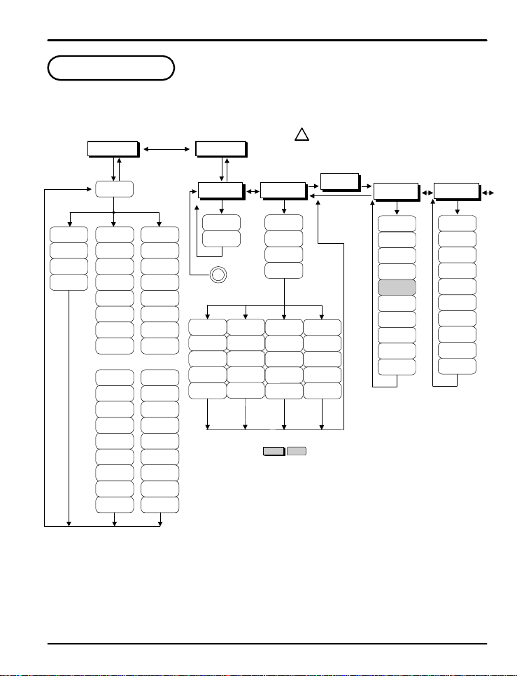
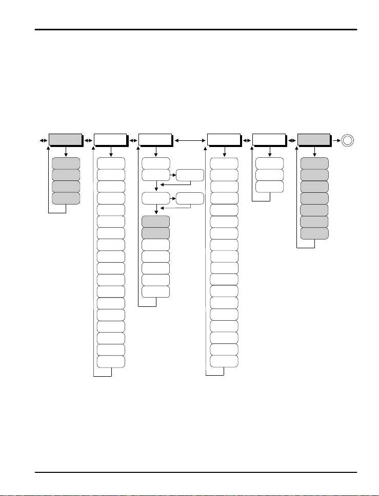
3. Parameter Map
PwD: Lockout Pass word
?
PROG STUP
WSET/ENT
PTNO
SET/ENT
PTNO=2
PTNO=0 PTNO=1
TMU 1.LC 2.LC
STCWZ1.SSP
1.SP1
WTM
1.TM1
1.TS1
1.SP2
1.TM2
1.TS2
2.SSP
2.SP1
2.TM1
2.TS1
2.SP2
2.TM2
2.TS2
...
1.SPE
1.TME
1.TSE
1.SPF
1.TMF
1.TSF
1.RPT
1.REN
1.RST
2.SPE
2.TME
2.TSE
2.SPF
2.TMF
2.TSF
2.RPT
2.REN
2.RST
ST
...
SET/ENT
1.P
1.I
1.D
1.MR
1.RP
G.AT
AT
AT-G
B
W
SET /
ENT
2.P
2.I
2.D
2.MR
**
2.RP
ST
G.PID
ARW
C.MOD
FUZY
PID
3.D
3.MR
RHY
Use th e ST arrows to enter the
NOTE
password an d p ress t h e SE T/ENT
key. The default password is 0.
SET/
PWD
S
ENT
G.CTL
SET/
ENT
T
PE.TM
US1
US2
LOCK
DI. SL
OSTS
3.P
4.P
3.I
4.I
4.D
4.MR
**
RDV
DSP.H
DSP.L
U.PWD
INIT
: Optional feature
: Valid only when I=0
*
: Menu only used if O U T2 or OU T3 set to H EA T
**
: Optional feature on some models
***
: Not available on all models
****
SET/
ENT
ST
G.IS
1.IST
1.ISB
1.ISH
1.ISL
1.ISD
2.IST
2.ISB
2.ISH
2.ISL
2.ISD
SET/
ENT
12
Page 13
PD550 Series Nova Programmable Process and Temperature Controller Instruction Manual
ST
G.DO
DO1
DO2
DO3
DO4
ST
SET/ENT
G.IN
SET/ENT
IN-T
IN-U
IN.RH
IN.RL
IN.DP
IN.SH
IN.SL
IN.FL
BSL
RSL
BSP1
BSP2
BSP3
BS0
BS1
BS2
BS3
BS4
ST
G.OUT
OUT1
OUT2
OUT3
***
SUB1
SUB2
O.ACT
CT
OH
OL
PO
SET/ENT
****
ST
HEAT
HEAT
ST
G.ALM
SET/
ENT
ALT1
AL-1
AL1.H
**
AL1.L
A1DB
A1DY
ALT2
G.RET
RET
RETH
RETL
SET/
ENT
ST
G.COM
SET/ENT
COM.P
BAUD
PRTY
SBIT
DLEN
ADDR
RP.TM
T
B
AL-2
AL2.H
AL2.L
A2DB
A2DY
ALT3
AL-3
AL3.H
AL3.L
A3DB
A3DY
13
Page 14
PD550 Series Nova Programmable Process and Temperature Controller Instruction Manual
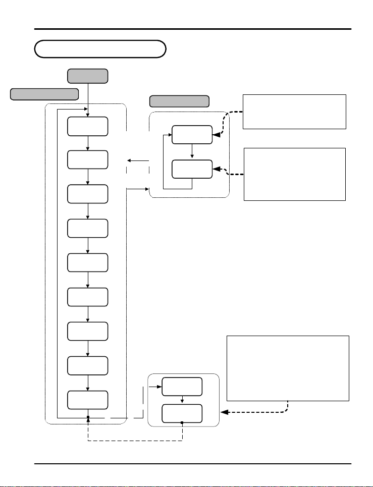
4. Operation Fl ow Ch a rt
Power On
Operation D i s p l ay
PV Display
"Stop"
ENT
PV Value
SP Value
ENT
PV Value
OUT Valu e
ENT
"N.SEG"
Segmen t #
ENT
"R-TM "
Run Time
ENT
"STEP"
OFF
ENT
"HOLD"
OFF
ENT
"H.SP"
Prog SP
ENT
"H.TM"
Seg Time
Group Dis p l ay
(note 1)
SET/ENT
key for 3 sec or
no keystroke for
60 sec
(note 2)
SET/ENT
key for 3 sec
(note 3)
note 1 : SP display reads 'STOP' when the controller outputs are off, such as when a
(note 4)
note 2: This is th e de f a u l t d is p l ay when the controller turns on.
note 3: Output co n t r o l d is p la y shows le vel of ou t p u t a s % o f f u l l o ut p u t s ca l e .
note 4: Displays program segment number in process.
note 5 : Display of the time le f t t h a t t h e c u r r e n t s e g me n t is r u n n i n g f o r .
(note 5)
note 6 : The STEP feature is u se d t o j u mp t o t h e n e xt prog r a m se g me n t . Turning t h is
note 7 : Menu used to set the p rogr a m t o H O L D , a n d s t o p t h e progr a m in i t s c u r rent s t a t e .
note 8: Displays the act i ve set poi n t wh il e i n H O L D . This set p o in t ma y be changed,
(note 6)
note 9 : Displays the time le f t in t h e c u r r e n t s e g me n t whi l e in H OLD. This t i me c a n b e
note 10 :Only displayed when User Screen 1 is set by US1.
note 11 :Only displayed when User Screen 2 is set by US2.
(note 7)
(note 8)
PROG
S or T
STUP
program is not r unning.
feature ON will immediately force the pr og ra m to th e ne xt progr am segment .
altering the set poin t o f t h e c on t rolle r wh i le i n H O L D mode.
changed, alterin g t h e t ime le f t i n t h e se g me n t when HO LD is turned off.
US1
(note 9)
*NOTE 10
US2
*NOTE 11
This menu contains parameters to set
the time unit, wait zones, program
pattern s, e n d o f p r o g ram behav ior,
and time signals.
This menu contains the parameter
used to setup the inputs and output s
as well as the parameters for general
controller func t io n . These must b e
set prior to controller operation.
US1 and US2 are set by the user to display
selected parameters in the operation display.
The parameters to be displayed are set from
parameters US1 a n d U S2 i n G . CTL . The
Table of D-Registers pro vides the n u mb e r t o
determine what parameter is displayed b y
each. Parameters displayed here may b e
altered in this display as they are normally.
14
Page 15
PD550 Series Nova Programmable Process and Temperature Controller Instruction Manual
5. Controller Parameter Setup
5.1 Input Group (G.IN)
PV
!
CAUTION
PV
Input group parameters should be established first, as changes to the input type may reset other
parameter settings in o t h e r g roups to their default value.
Press SET/ENT key to sel e ct i n p u t g r o u p . P r e s s p ress S or T key to cycle thr o u gh
groups as sho wn b e lo w. (Refe r to p aramete r map in se c t io n 3 . )
G.AT Q G.PID Q PWD Q G.CTL Q G.IS Q G.DO
T
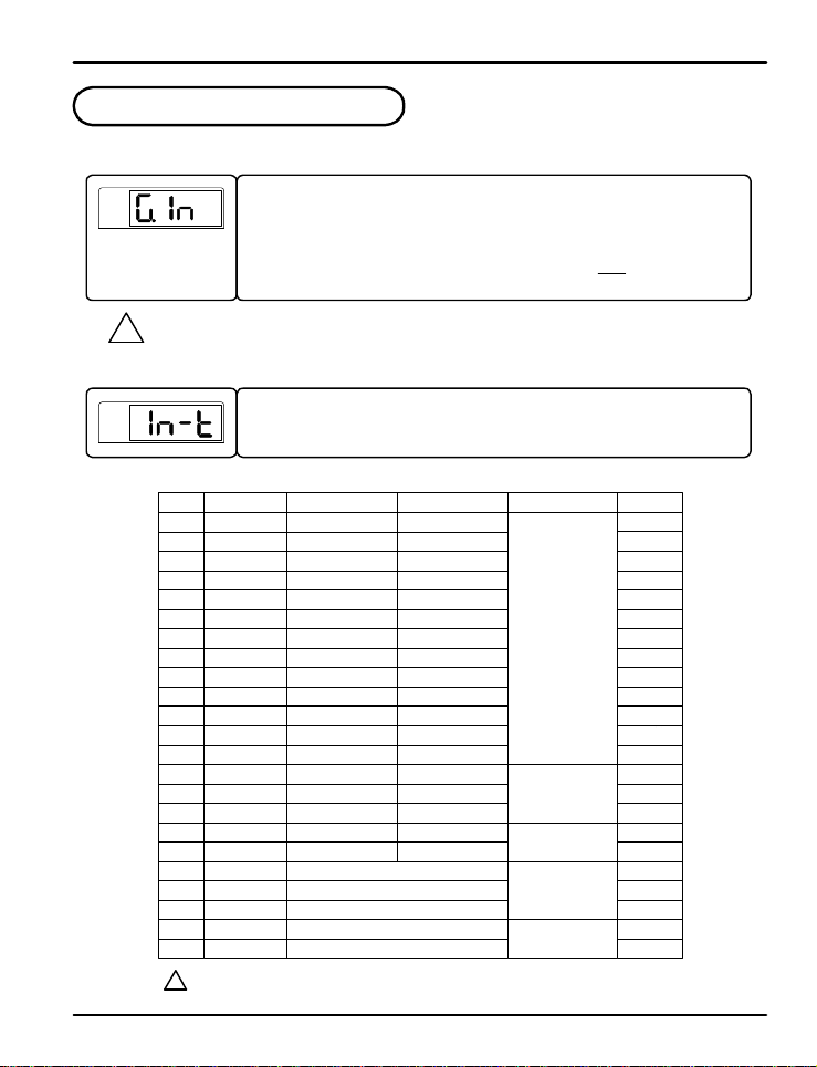
This parameter sel e ct s t h e t y p e o f i nput sensor used. Its default setting is type TC.K1.
Refer to the fo l l o win g t a b l e s h o wi ng t h e t ype o f se n s o r i np u t s a n d se l e ct t h e d e s ired in p u t
type.
Table 1: Universal In pu t Se l ecti o n
TYPE
K1
K2
J
E
T
R
B
S
L
N
U
W
PtA
PtB
PtC
JPtA
JPtB
1 to 5V
Temp.Range (ºC)
-200 to 1370
-199.9 to 999.9
-199.9 to 999.9
-199.9 to 999.9
-199.9 to 400.0
-199.9 to 900.0
-200 to 1300
-199.9 to 400.0
-199.9 to 850.0
-199.9 to 500.0
-19.99 to 99.99
-199.9 to 500.0
-150.0 to 150.0
No.
1
2
3
4
5
6
7
8
9
10
11
12
Platinel II
13
14
15
16
17
18
0.4 to 2.0 V
19
20
0 to 10 V
21
-10 to 20m V
22
0 to 100mV
23
4-20 mA Input Selection:
?
To accept a 4-20 mA signal, select 0.4 to 2.0 VDC input and connect a 100 Ω resistor across the input terminals.
NOTE
ST ST ST ST ST
K R
G.COM Q G.RET Q G.ALM Q G.OUT Q G.IN
Temp.Range (ºF)
-300 to 2500
0 to 230 0
-300 to 2300
-300 to 1800
0 to 1700
0 to 1800
0 to 1700
0 to 2300
0 to1390
-10.00 to 20.00mV
-300 to 750
32 to 3100
32 to 3300
32 to 3100
-300 to 1600
-300 to 2400
-300 to 750
32 to 4200
32 to 2500
-300 to 1560
-199.9 to 999. 9
-4.0 to 212.0
-199.9 to 999. 9
-199.9 to 300. 0
0.400 to 2.000V
1.000 to 5.000V
0.00 to 10. 0 0 V
0.0 to 100.0mV
STSTSTST
display range : -5% to 105%
Group
Thermocouple
RTD
(0.00385)
RTD
(0.00392)
VDC
mVDC
ST
DISP
TC.t1
TC.t2
TC.J
TC.E
TC.T
TC.R
TC.B
TC.S
TC.L
TC.N
TC.U
TC.y
TC.PL
PTA
PTB
PTC
JPTA
JPTB
2v
5v
10v
20Nv
100n
1
1
n
-
-
-
-
-
-
-
15
Page 16
PD550 Series Nova Programmable Process and Temperature Controller Instruction Manual
PV
PV
PV
PV
PV
PV
PV
PV
PV
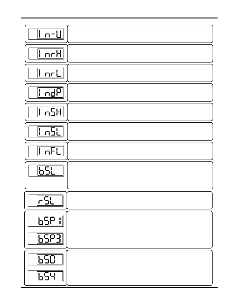
This parameter sets t h e d is p la y tempe rature un it f o r ºC or º F .
Its default se le c t io n i s º C.
Refer to Table 1 when changing the temperature unit for the temperature input range.
This paramete r se t s t h e h ig h l imi t o f t h e t e mpe ratu r e d is p l ay range (maximum temperature
displayed). F o r mV and V inputs, this sets the value of the high input of the input scale
defined in In.SH.
This para me t e r s et s t h e lo w l i mit o f t h e t e mpe rature dis p la y ran g e ( min i mu m te mp e r a t u re
displayed). Fo r mV a nd V i n p u t s, t h i s s e ts t h e lo w i n p u t o f t h e in p u t s ca l e de f i ned in In.SL.
This parameter set s t h e p o si t io n o f t h e d e c ima l p o i n t f o r mV o r V inputs. The position of
the decimal point can be set as 9999, 999.9, 99.99, or 9.999. Its default set value is 1.
The parameter to se t t h e h i gh l i mit o f t h e mV o r V disp l a y s ca l e . This va lu e will be
displayed when the input is set to the high input established in In.rH.
Its default value is 100.0.
The paramet e r to se t t h e lo w l i mit o f t h e mV o r V disp l a y s ca l e . This value will be display ed
when the input is set to the low input established in In.rL.
Its default value is 0.0.
The parameter to set the PV f i lt e r for st a b iliz a tio n fr o m electr omagn etic n oise and
interference. This will effect th e r at e o f change in the PV display value. I ts default setting
is OFF, and can be set within 1 to 120 seconds.
This parameter to establishes PV behavior when an open input sensor is detected. When
BSL is set to U P , t h e P V o p e rates a s i f a t t h e h ig h i nput range. When BSL is set to
DOWN, the PV operates a s if a t t h e l o w input r ange. I ts default setting is UP. In the case
of mV or V inputs, the default setting is OFF. An open sensor check is not performed in 10
V, 20 mV, or 100 mV input settings.
This parameter dete r min e s if RJC fo r t h e rmocou p le i n p u t s i s u s e d . R JC c a n b e t u r n e d
on or off. Its d e f a u lt s e t t in g i s ON.
PV
.
.
.
PV
PV
.
.
.
PV
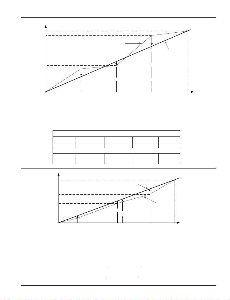
This parameter sets where th e PV b i a s p o i n t s o c cu r . S e e F i g 1 and Fig 2 for fur ther
information about input bias operation.
This parameter sets t h e b ia s value at t h e c o r r e s ponding bias point input values. These
parameters esta blish th e value of the o ffset at e ach of the def ined BSP1 - BSP3 poin ts .
See Fig 1 and Fig 2 fo r f u rthe r i nf o rmatio n a bout input bias operation.
16
Page 17
PD550 Series Nova Programmable Process and Temperature Controller Instruction Manual
0ºC = BS4
-3ºC = BS3
+1ºC = BS2
-2ºC = BS1
0ºC = BS0
Example 1:
Example 2:
Original Temper a t u r e
-2ºC
RL BSP3 RHBSP1 BSP2
The original temperature is shown within the range of 0ºC (Range Low) and 100ºC (Range High).
Bias point s h a ve been used to adjust the displayed temperature as shown in the graph in Fig 1.
To establish this bias, the settings are shown below.
0ºC = BS4
50ºC = BS3
10ºC = BS2
10ºC = BS1
0ºC = BS0
Tempe r a t u r e B ias Value (B S 0 t hrough BS4) = Temperature After Bias - Actual Temperature
Display temperature after bias at 600 ºC actual temperature = P
25ºC
Fig 1: Temperatu r e B i a s
Temperature Settings to Establish Where the Bias Occurs
RL BSP1 BSP2 BSP3 RH
0ºC 25ºC 50ºC 75ºC 100ºC
Bias Offset for Each Point
BS0 BS1 BS2 BS3 BS4
0ºC -2ºC +1ºC -3ºC 0ºC
+10ºC
BSP1
100ºC0ºC 500ºC 800ºC 1000ºC
Fig 2: Bias Formula Calcul a t i on
P = 600 + (600 - BPS2) x
P = 600 + (600 - 500) x
+1ºC
50ºC 100ºC
Temperature After Bias
+10ºC
+PºC
Original
600ºC -
Temp
BSP2 BSP3RL RH
BS3 - BS2
BSP3 - BSP2
50 - 10
800 - 500
-3ºC
Temperature
After Bias
75ºC0ºC
+50ºC
Original
Temperature
+ BS2
+ 10 = 623ºC Temperature After Bias
BS4
17
Page 18
PD550 Series Nova Programmable Process and Temperature Controller Instruction Manual
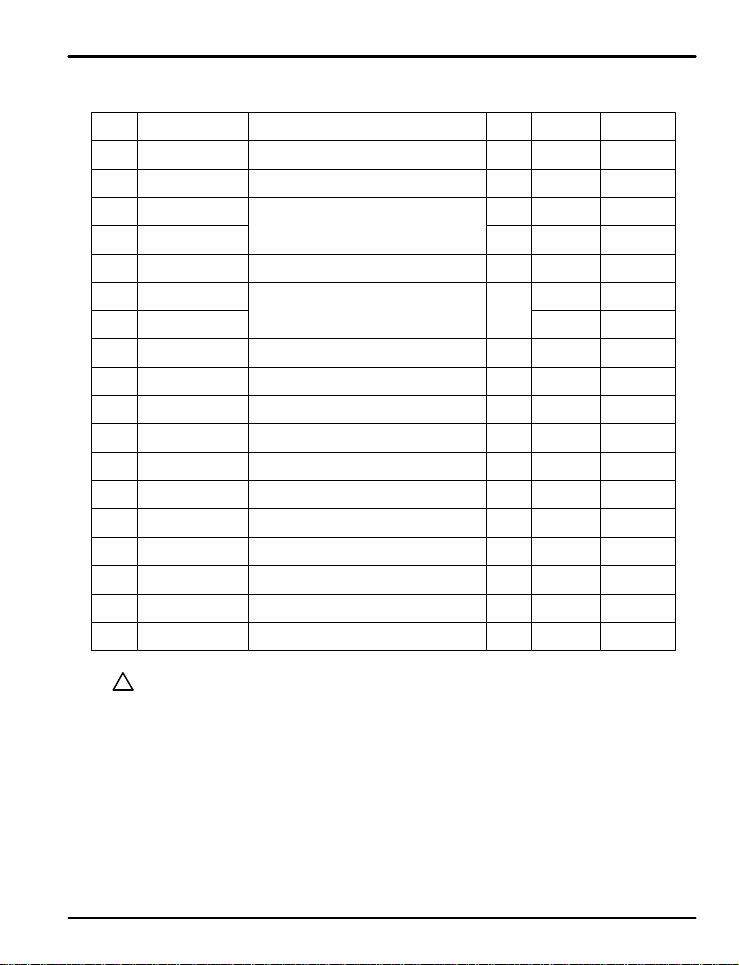
Input Group Parameter Summary
Display Parameter
IN-T
IN-U
IN.RH
IN.RL
IN.DP
IN.SH
IN.SL
IN.FL
BSL
RSL
BSP1
BSP2
BSP3
BS0
BS1
BS2
BS3
BS4
NOTE
Input Ty p e
Display Unit
Max PV
Display R ange
Min PV
Display R ange
Decimal Po i nt
Position
Max Input Valu e
Scale
Min Input
Value Scale
PV Filter
Open Sensor
Behavior
RJC Operation
Reference Bias
Point 1
Reference Bias
Point 2
Reference Bias
Point 3
Bias Value for RL
Point
Bias Value at BSP1
Bias Value at BSP2
Bias Value at BSP3
Bias Value
at RH
There are two types o f e n g in e e r i n g u n it s values us e d i n t h e se t t i n g o f p a r a me t e r s , a b so l u t e
?
engineering units (AEU) and general engineering u n i t s ( GEU) . A n AE U p a ramete r i s se t u s in g a n
absolute value engineering unit that represents a specific point, such as a specific temperature or
voltage level. An GEU parameter is set using engineering units, however it is a general value, and
not tied to any input or output level.
For example: When establishing input bias, parameter BSP1 sets the specific PV value where bias
point one will occur . T h is pa ra meter ha s a u nit d esignation of AEU. BS1, the amount of offset at
BSP1 is set in engineering units, however this parameter occurs at whatever BSP1 is set to, and
therefore does not hav e an absolute setting related to any input or output, it is just the amount of offset
at where BSP1 occurs. While one is related to an absolute input value, and the other stand alon e
value, both are se t a s engineering units, such as BSP1 set as 100ºC and BS1 set as 3ºC.
Refer to Table 1: Universal Input Selection
Setting Range
ºC / ºF
Within sensor i nput range
Refer to Table 1
INRH > INRL
0, 1, 2, or 3
-1999 to 9999
Decimal position determined by IN.D P
INSH > INSL
OFF, 1 t o 1 20
OFF, UP, DOWN
ON, OFF
AEU (0.0 to 100.0%),
RL≤BSP1≤BSP2 ≤BSP3≤RH
AEU (0.0 to 100.0%),
RL≤BSP1≤BSP2 ≤BSP3≤RH
AEU (0.0 to 100.0%),
RL≤BSP1≤BSP2 ≤BSP3≤RH
GEU (-100.0 to 100.0%)
GEU (-100.0 to 100.0%)
GEU (-100.0 to 100.0%)
GEU (-100.0 to 100.0%)
GEU (-100.0 to 100.0%)
Unit Default Remark
ABS TC.K1
ABS
AEU 1370
AEU -200
ABS 1 mV, V
ABS
ABS UP
ABS ON
AEU
AEU
AEU
GEU 0
GEU 0
GEU 0
GEU 0
GEU
ºC
100. 0 mV, V
0.0 mV, V
sec OFF
AEU
(100.0%)
AEU
(100.0%)
AEU
(100.0%)
0
T/C, RTD
Not Used for
VDC Input
Only Used for
TC In pu t
18
Page 19
PD550 Series Nova Programmable Process and Temperature Controller Instruction Manual
5.2 Output Group (G.OUT)
PV
PV
PV
PV
PV
PV
PV
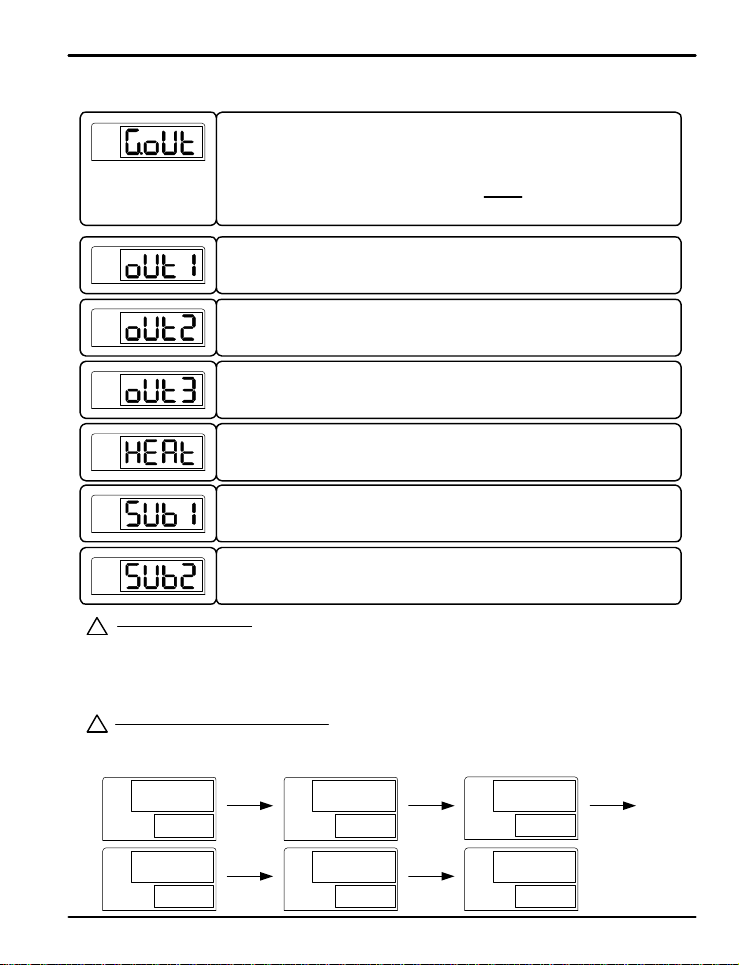
Output Op e r a t i o n Se t t i n g s:
?
HEAT is used to set the output for PID control, as time-proportional control for relay outputs or 4-20 mA or voltage
NOTE
pulse outputs for analog outputs. RUN will set the relay s to alway s o n. If set for TS (time signal) the relays will
trigger if the time signal is on for the current program segment (see 1.TS1 under PROG menu). PEND will trigge r
relay outputs after the p r o g r a m c y c le e n d s f o r t h e t i me s e t in P E . TM under G.CTL. For additional information on the
setup of ALM1, ALM2, ALM3 (alarm), IS1, and IS2 (inner signal) refer to G.ALM and G.I S.
Output Gr oup Menu Pr ogression Example:
?
The following settings establish relay out put 1 (OUT1) to trigger based on alarm 1, for analog output 2 (OUT 2) to
NOTE
operate as a heating temperature controller outputting a voltage pulse, for analog output 3 (OUT 3) to output a
retransmitting 4-20 mA signal, and for aux iliar y r elay o utp uts SU B1 an d SUB2 to t r igger with alarm 2 and alarm 3.
PV
oUT1 oUT2
SP
alN1
PV
oUT3
SP
ret
Press SET/ENT key to sele ct i nput group. ( Refer to par ameter map in section 3.)
ST ST ST ST ST
G.AT Q G.PID Q PWD Q G.CTL Q G.IS Q G.DO
K R
T
G.COM Q G.RET Q G.ALM Q G.OUT Q G.IN
This parameter sets th e t y p e o f operation for output 1. ( OU T 1: relay output)
The output can be set to HEAT (PID Control), ALM1, ALM2, ALM3, RUN, IS1, IS2, TS, or
PEND. Its defaul t se t t i n g is AL M 1 . S e e N o t e s b e l o w.
This parameter esta b l is h e s t h e t ype of oper ation for output 2. (O UT2: 4-20 mA or voltage
pulse) This output can be set for HEAT (PID Control) or RET (Retransmitting). Its
default setting i s H EA T.
This parameter esta b l is h e s t h e t ype of oper ation for output 2. (O UT3: 4-20 mA or voltage
pulse) This output can be set for HEAT (PID control) or RET (retransmitting). Its default
setting is H EA T. Menu ap p e a rs onl y o n mo d e ls wit h t h e OUT 3 o u t p u t .
This parameter selects the type o f o u t p u t si gnal for each analog output (OUT2 and OUT3)
when they are se t t o H E A T. The o u t p u t s c a n b e se t t o S S R ( p u l se o u t p u t ) o r
SCR (4-20 mA). Its d e f a u lt s e t t i ng i s SS R .
This parameter sets t h e t y p e o f oper ation for aux ilia r y out put 1 ( SU B1: re lay o utp ut )
Output can be set to HEAT, ALM1, ALM2, ALM3, RUN, I S1, I S2, T S, or PEND. Its default
setting is ALM2. Menu appears only on models with the SUB1 output option.
This parameter sets t h e t y p e o f oper ation for aux ilia r y out put 1 ( SU B2: re lay o utp ut )
Output can be set to HEAT, ALM1, ALM2, ALM3, RUN, I S1, I S2, T S, or PEND. Its default
setting is ALM2. Menu appears only on models with the SUB2 output option.
PV
SP
~
HEAT
PV
sUB1 SUB2
SP
aln2 Aln3
~~
PV
HEAT
SP
PV
SP
STSTSTST
ssr
ST
19
Page 20
PD550 Series Nova Programmable Process and Temperature Controller Instruction Manual
PV
PV
PV
PV
PV
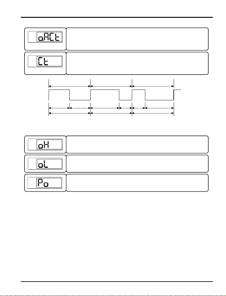
This parameter establishes reve r s e (REV) or f o r wa rd (F WD) a c t ivation o f t h e co n t rol
outputs. In forwar d op er at ion , t he co nt r ol ou tp uts will be most act ive when the PV value is
higher than the SP, as t h e c o n t r o l le r acts t o l o we r t h e P V . In re verse op e r a t i o n, t h e c o n t r o l
outputs will be most act ive when the PV value is lower than the SP v alue, as the controlle r
acts to increa se t h e P V. The defa u l t se t t i n g is R EV .
This parameter esta b l is h e s t h e c y c le t i me f o r u s e wit h t i me-pro p o r t ional PI D r elay or
voltage pulse cont rol whe n t h e o u t p u t s a re set t o H E AT or COOL. The cycle t ime c a n b e
set from 1 to 3 0 0 se c o n d s. Its defau l t se t t i n g is 2 se c onds.
Output=50% Output=70% Output=30%
5 Sec
5 Sec
CT=10 Sec
Fig 3: Time-Proportional PID Control Output
This parameter sets a hig h l imi t f o r t h e le vels of t he c o n t r o l o u t p u t . This li mit s t h e o u t p u t
levels based on a percentage of their full scale. Its default setting is 100 (%).
This parameter sets a lo w l imi t f o r t h e l evels of t h e co n t r o l o u t p u t . This prevents th e
outputs from drop p in g b e l o w a ce rtain le vel based o n a p e rcentage of their full scale. Its
default setting is 0 (%). The outp u t s are limit e d b y both t h e t h e l o w a n d h ig h l imi t s.
This parameter establishes the percent output transmitted by the control outputs when the
controller is in STOP mode, or when an error condition occurs such as a PID algorithm
error, A/D error, or open sensor error is detected.
7 Sec
CT=10 Sec CT=10 Sec
Cycle Time (CT) set t o 1 0 s ec onds
3 Sec
3 Sec
7 Sec
20
Page 21
PD550 Series Nova Programmable Process and Temperature Controller Instruction Manual
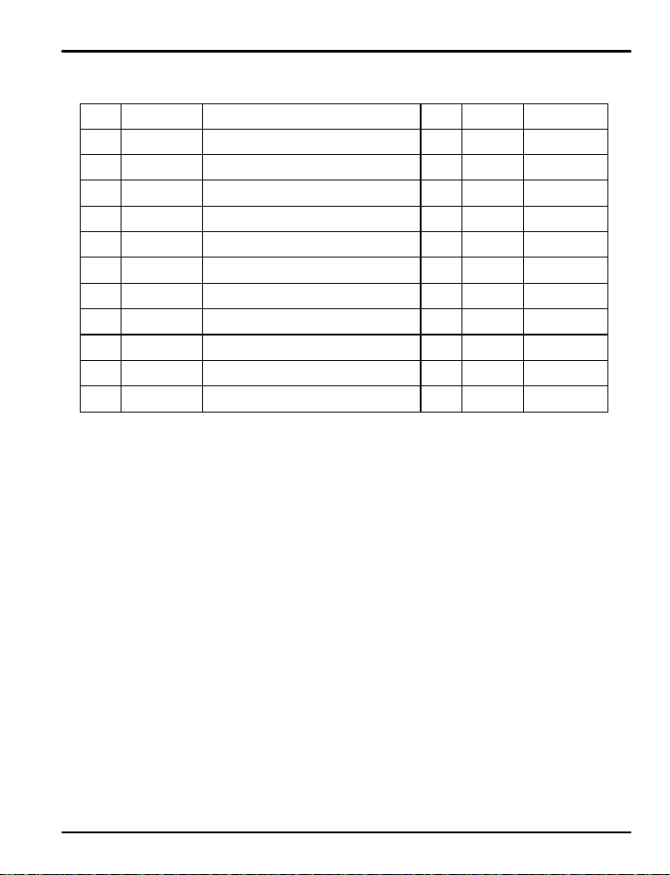
Output Group Parameter Summary
Display Paramete r
OUT1
Select Output
OUT2
Select Output
OUT3
Select Output
Select Output
HEAT
SUB1
SUB2
O.ACT
CT
OH
OL
PO
Type
Select Output
Select Output
Reve rse and
Forward
Cycle Time 1
High Limit
of Output
Low Limit
of Output
Preset Output
HEAT, ALM1, ALM2, ALM3, IS1, IS2, TS,
HEAT, ALM1, ALM2, ALM3, IS1, IS2, TS,
HEAT, ALM1, ALM2, ALM3, IS1, IS2, TS,
Setting Ra n g e
PEND, RUN
HEAT, RET
HEAT, RET
SSR, SCR
PEND, RUN
PEND, RUN
REV, FWD
1 to 300 seconds
OL + 1 digit to 105.0%
OH>OL
-5.0% to OH se t t in g
OH>OL
-5.0 to 105.0%
Unit Default Remark
ABS ALM 1
ABS HEAT
ABS RET
ABS SSR
ABS ALM2 Option
ABS ALM 3 Option
ABS REV
sec 2 sec
% 100.0%
% 0%
% 0.0%
Models with
OUT3 Only
When OUT2 or 3
is Set to HEAT
21
Page 22
PD550 Series Nova Programmable Process and Temperature Controller Instruction Manual
5.3 Control Group (G.CTL)
PV
PV
PV
PV
PV
PV
Press SET/ENT key to sel e ct c o n t r o l g r o u p . ( R e f e r to p aramete r map in se c t io n 3 . )
ST ST ST ST ST
G.AT Q G.PID Q PWD Q G.CTL Q G.IS Q G.DO
K R
T
G.COM Q G.RET Q G.ALM Q G.OU T Q G.IN
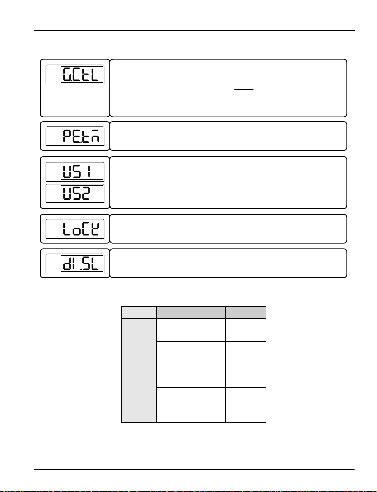
This parameter establishes how long after a program ends the relay outputs will trigger
for if set to PEND. Its de f a u l t se t t i n g is 1 5 se c o n d s. This para me t e r i s a lwa ys set in
seconds.
This parameter estab l is h e s t h e u s e r sc r e e n s f o r viewing, c o n f irmatio n , and setup of
commonly used parameters from the operation display. To add the parameter to t h e
operation display, en t e r t h e co rresp onding number for the parameter from the Table of DRegisters as either US1 or US2 . The defau l t s etting s a re OF F.
See page 14 and the Operation Flow Chart for a map of the operation display.
&
Turning ON this parameter locks all setting s fr om bein g changed. This applies to the
operation display f u n ct i o n s, s u ch a s changing the set point, as well as setting group
parameters. If ON, on l y t h e L OCK pa ramete r may b e ch a nged. The default setting is OFF.
This parameter establishes the operation of the digital input (DI) external contacts. The
digital input operating configura t i o n s a re sho wn i n Table 2 : D I Opera t io n . This feat u r e i s
only val id f o r mo d e l s wi t h d ig i t a l i nputs.
Table 2 : DI Operatio n
DI. SL DI1 DI2 Opera t io n
OFF - - DI Disabled
off - HOLD OFF
1
2
on - HOLD ON
- off ST EP OFF
- on STEP ON
off - RESET
on - PRO G RUN
- off PROG1
- on PROG2
STSTSTST
ST
22
Page 23
PD550 Series Nova Programmable Process and Temperature Controller Instruction Manual
PV
PV
PV
PV
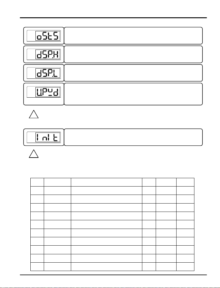
Be sure not to f orget t h e p a s sw ord on ce i t h a s been set. I f the password is forgotten, contact technical
!
CAUTION
CAUTION
support as listed on the back of this manual.
PV
Most parameters will be reset to the i r d e f a u l t se t t i n gs when the controller is initialized. Note the current
!
settings before this is do n e s o t h e y c a n e a si l y b e r e s t o r e d a f t e r c o n t r o l le r init ia l izatio n .
Control Group Parameter Summary
Display Paramete r
PE.TM
US1
User Scre e n
US2
User Scre e n
LOCK
Parameter Lock
DI. SL
DI Selection
Output Status
OSTS
Display High
DSP.H
DSP.L
Display Low Limit
U.PWD User passwo rd 0 to 9999 ABS 0
INIT
When this para meter is on , t he o ut put set tin gs will be d isplay e d in the operation display.
The settings of parameters OU T1, OUT2, O U T3, SUB1 , an d S U B 2 will be shown. O nly
outputs built into t h e mo d el b e i ng u s e d will disp lay . I ts d ef au lt set tin g is O F F .
This parameter sets t h e h ig h l imi t o f t h e s e n so r input in the PV display. The PV value will
not display hi g h e r t h a n t h is l imit , h o we ver the co n t rol fu n ct i o n s will operate based on the
actual input value.
This parameter se t s t h e lo w l imi t o f t h e se n s o r input in the PV display. The PV v alue will
not display lower th an this limit, h owever the control fun ctio ns will operate based on the
actual input value.
This parameter estab l is h e s t h e p a s swo r d f o r the co n t r o l le r. T h i s p a s swo rd must b e
entered at the PWD screen before accessing the control group ( G.CTL) or it will not
access the settin g grou p s a f t e r the PWD p r o mp t . The defa u lt s e t t in g i s " 0 " . S e e t h e
parameter map in section 3 for the location of the PWD prompt in the group menus.
This parameter resets most parame t e r s t o t h e ir fact o r y sett i n g s. To reset t h e co n t rolle r ,
set this parameter to ON. After r e s e t , it will r e tu rn to the O F F se tt ing.
Pattern End
Alarm Ti me
Display
Limit
Factory
Initialization
Setting Range
OFF, 1 to 9999 sec s ec o nds
OFF, D-Register Numb e r 1 t o 1299
OFF, D-Register Numb e r 1 t o 1299
OFF, ON (No Editing)
OFF, 1 , 2
OFF, ON
AEU (-5.0 to 105.0%), DSP.L<DSP.H
AEU (-5.0 to 105.0%), DSP.L<DSP.H
OFF, ON
Unit Default Remark
ABS 15 (sec)
ABS OFF
ABS OFF
ABS OFF
ABS OFF DI Opti o n
ABS OFF
AEU
AEU AEU (-5.0%)
ABS OFF
AEU
(105.0%)
23
Page 24
PD550 Series Nova Programmable Process and Temperature Controller Instruction Manual
5.4 Program Group (G.PROG)
PV
PV
PV
?
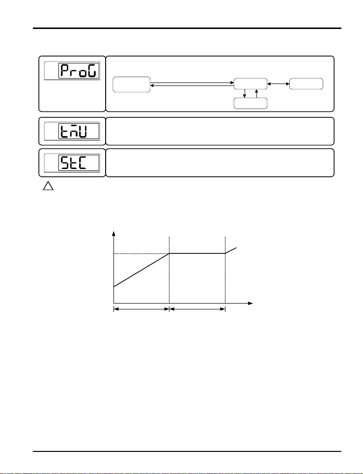
STC Operation
NOTE
SSP START (S TC set t o SSP)
In Start Set Point mode, the program will begin with at t he d ef ault set p oint set in th e pr og r am (SSP) and r amp
to the set point v a l u e f o r s e g men t 1 (SP1) o ver the t ime d e s ignated in time segment 1 (TM1).
For a soak seg me n t , t h e se t p o i n t f o r t h e s e g men t i s t h e s a me as t h e se t p o i n t p r i o r t o t h e s oa k s eg me n t . In this
case, the progr am will hold t he se t p oint at th at value for the length of the segment. In the above example, 1.SP1
and 1.SP2 are the same, and the set point is steady for the time indicated in 1.TM2.
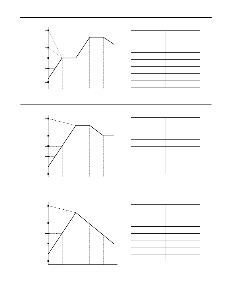
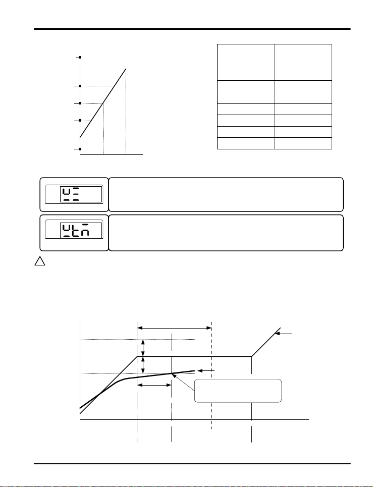
PV Start (S TC set to P V )
In PV mode, the program will immediately start a t t he p oin t in the pr og r am where th e set po int is equal to the
PV value when the program starts running. In the case where the PV is beyond any set point in the program,
the program will immediately start at be ginn ing of the fir st soak se gment . If no soak segment is pr ese nt in th e
program, it will start at the poin t clo sest to th e PV.
If the starting point o f t he p rogr a m, b a se d o n t h e P V a t t h e s t a r t o f t h e p r o g ram, wou l d o cc u r d u r i n g a r a mp
segment, the program will recalculate t he time lef t in t he r amp segment . The rate of set point change in the
ramp will remain the sa me, and the progr am will calculate how much time r emains in th at se gment based on
the original rate of change characteristics from the set point of the last segment to the SP of the ramp
segment. Refer to the graphics on the following pages for additional information.
Select PROG group from the group display. (Refer to parameter map in section 3.)
Operation
Display
This parameter esta b l is h e s t h e t i me u ni t s t h e c o n t r o l le r uses f o r p r o g rams an d
parameters. This can be set t o t h e f o r ma t o f H H . M M ( hour s.minutes) or MM.SS
(minutes.seconds). It s d e f a u l t se t t i n g is H H . M M .
This parameter sets the start code to determine what method of SP operation is used when
a program starts. STC (start code) can be set for SSP ( sta rt ing set p oint) or PV ( pr ocess
variable start). Se e be l o w f o r d e t a i ls . The d e f a u lt s t a r t co d e i s P V .
1.SP1
1.SSP
Hold SET/ENT for 3 s e co nds
Hold SET/ENT for
3 seconds or
no keystroke for 6 0
seconds
Segment 1 Segment 2
1.TM1 1.TM2
Fig 4: Start Code SSP Sta rt
PROG SETUP
SET/ENT
PTNO
SP
ST
SFT
24
Page 25
PD550 Series Nova Programmable Process and Temperature Controller Instruction Manual
STC set t o P V, f i r s t so a k a t se g me n t 2
5
A
4
3
2
Input Va lu e a t P rogr a m S t a rt
1
STC set t o P V, f i r s t so a k a t se g me n t 3
5
4
3
2
Input Va lu e a t P rogr a m S t a rt
1
STC set to PV, with no soak segment in the program
C
D
E
1 2 3 4
C
D
E
1 2 3 4
B
Program Segment
A
B
Program Segment
Program Set Point
Program Set Point
Starting P V A t
Program Ac t ivation
5
4
3
2
1
Starting P V A t
Program Ac t ivation
5
4
3
2
1
Immediate
Program
Start Po i nt
C
C
C
D
E (SSP)
Immediate
Program
Start Po i nt
A
B
C
D
E (SSP)
5
4
3
2
D
Input Va lu e a t P rogr a m S t a rt
E
1
1 2 3 4
A
B
C
Program Segment
Program Set Point
25
Starting P V A t
Program Ac t ivation
5
4
3
2
1
Immediate
Program
Start Po i nt
A
B
C
D
E (SSP)
Page 26
PD550 Series Nova Programmable Process and Temperature Controller Instruction Manual
STC set to PV, with only ascending ramp segments
5
4
3
2
D
Input Value at Program Start
E
1
1 2
Program Segment
PV
PV
?
Wait Function
NOTE
The wait function delays the start of the next program segment, if the next segment is a soak segment (the new
target set point is the same a s t h e prev i o u s t a rget s e t p o in t ), unt i l t h e PV i s wi t h in a s p e ci f ie d d e viation range
from the SP, or until the wait time has expired. T he wait zone defines the deviation range fr om the SP the PV
must reach to activ at e t he n ext segment and the wait time est ab lishes a limit on ho w long t he p r ogr a m will wait for
this to occur before act ivating t h e n e xt segment . N o t e t h a t t h i s f u n c t io n will on ly act ivate when progressing into a
set point soak segment.
A
Program Set Point
B
C
This is parameter est a b l is h e s t h e wa i t z one r ange for the wait function. This sets the
deviation value used for the wait function. When set, a running program will not mov e to th e
next segment until the PV is within the wait zone, or the wait time has passed. When OFF,
the wait functi o n will not be enabled. See Fig 5 for more information about this process.
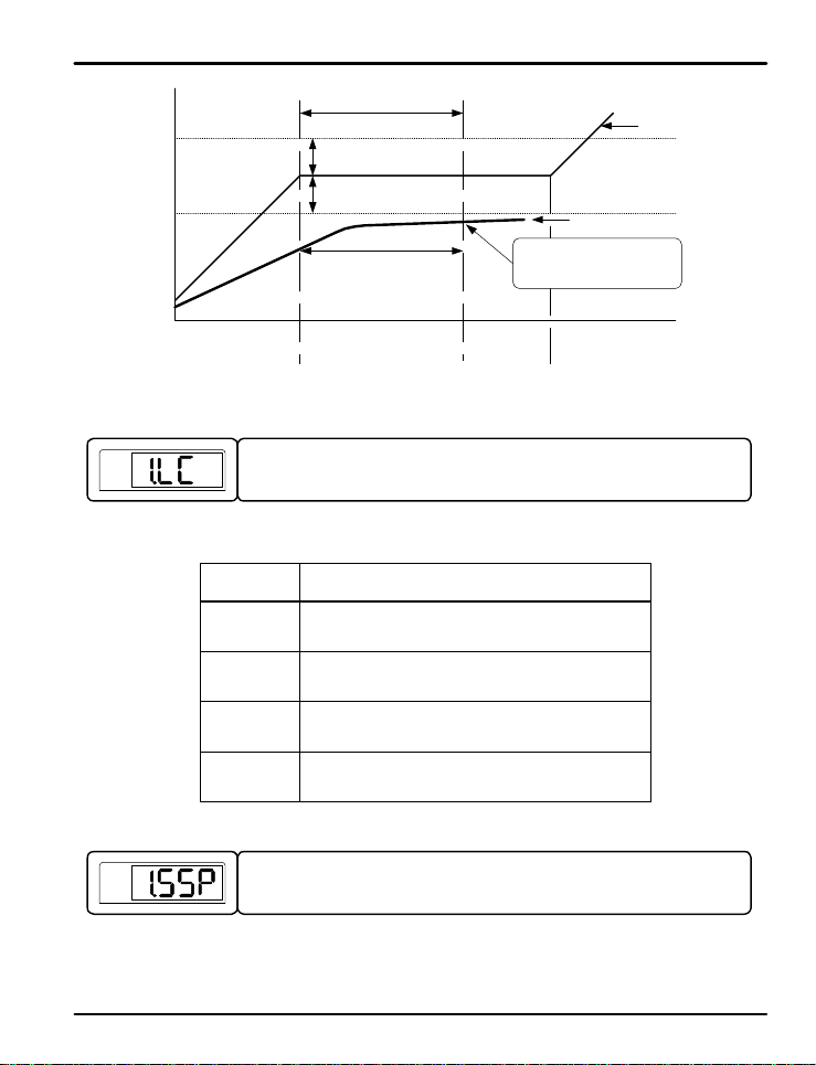
This is the wait t i me p a r a me t e r f o r the wa i t f u n ct i o n , wh i ch s e t s t h e t i me t h e p rogr am wi ll
wait for the P V to e n t e r the wa i t z one befor e starting the nex t pr ogram segment. The
setting range is OFF (0) to 99. 59 (time u n its set b y TM U ) . When OFF, the wait function
will not b e e n a b l e d. S e e F i g 6 f o r mo r e i n f o r ma t i o n .
WTM (Wait Time)
WZ (Wait Zone)
Starting P V A t
Program Ac t ivation
5
4
3
2
1
Immediate
Program
Start Po i nt
Program
Will No t S t a r t
B
C
D
E(SSP)
SP
Segment N
WZ
Actual Delay
Time
Time
Fig 5 : Wait Function Wait Zone Re l e a s e
26
PV
Point of Wait Function release.
Shift to Segment N+1
Segment N+1
Segment N+2
Page 27
PD550 Series Nova Programmable Process and Temperature Controller Instruction Manual
WTM (Wait Time)
WZ (Wait Zone)
WZ
Actual Delay Time
SP
PV
Point of wait time release.
Shift to Se gment_(n+1)
Segment N Segment N+1 Segment N+2
Fig 6: Wait Function Wait Time Release
PV
PV
The link parameter establishes the operation of the controller when a program has finished
running. The link co d e s t h at d e t e rmine t h e co n t roller operation when a program ends are
shown in Table 3 below.
Table 3 : Link Codes
Link Code Controller Operation When a Program is Complete
RST
HOLD
PTN1
PTN2
This parameter sets the st a r t i n g se t p o i n t f o r p rogr a m 1. This set p o in t i s u s e d wh e n t h e
program is set for a S TC of SSP, or to calculate the ramp time for segment 1 if needed
when STC is set to PV.
(Will enter STOP mode when RST key pressed)
Time
Shif t t o RESET ( St o p )
(All operation stops)
Continues to run at the last set point
Runs PTN1 (Program 1 )
(Program 1 will infinitely repeat if set in 1.LC)
Runs PTN2 (Program 2 )
(Program 2 will infinitely repeat if set in 2.LC)
27
Page 28
PD550 Series Nova Programmable Process and Temperature Controller Instruction Manual
PV
PV
PV
.
.
.
PV
PV
PV
PV
PV
PV
.
.
.
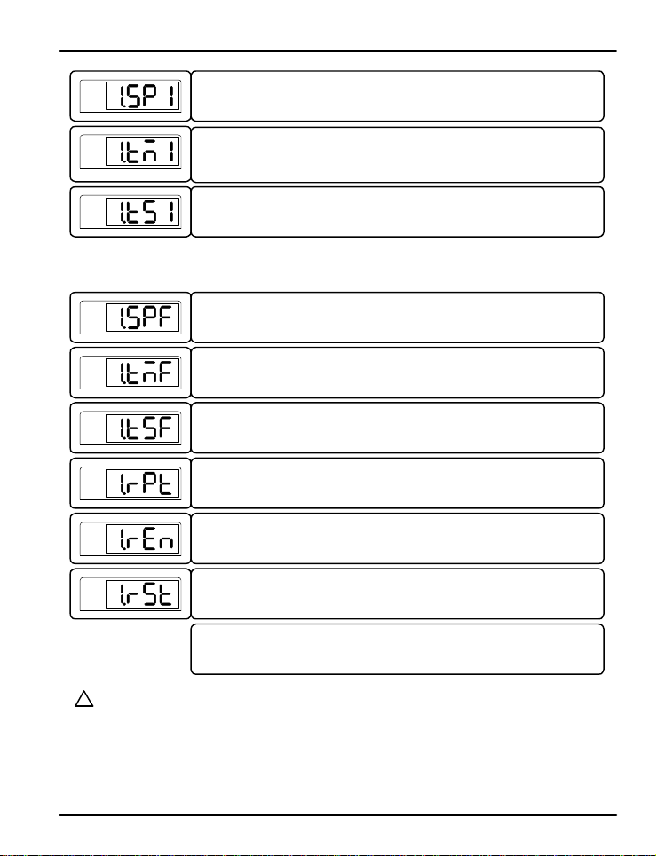
This parameter sets the targ e t se t p o i nt (TS P ) f o r p rogr a m se g me n t 1 . The p a r a me t e r i s
set in the same way for segments 1 to 15 (1.SP1 to 1.SPF).
This parameter sets the r u n n in g t i me f o r t h e se g me n t . This can be s e t a s OFF o r
1 to 99.59 (time unit set in TMU). I n t h e ca s e o f a n O FF set t i n g , t h e p r o g r a m will sto p
running after t h e p r e vious seg me n t . Th is p a r a me t e r i s s e t in t h e s a me way for s e g men t s 1
to 15 (1.TM1 to 1.TMF).
This parameter determines if the sta t u s o f t ime s ignal (TS) relay outputs are ON or OFF
for the duratio n o f t h e p r o g ram seg men t . This para me t e r is set in t h e s a me wa y f o r
segments 1 to 1 5 ( 1 . TS1 to 1. TSF) .
.
.
.
This parameter sets the target s e t p o in t (TS P) for p r o g ram seg men t 1 5 .
This parameter sets the r u n n in g t i me f o r se g me n t 1 5 . This can be s e t a s OFF o r
1 to 99.59 (time unit set in TMU). I n t h e ca s e o f a n O FF set t i n g , t h e p r o g r a m will sto p
running aft e r t h e p rev i o us s eg me n t .
This parameter determines if the sta t u s o f t ime s ignal (TS) relay outputs are ON or OFF
for the duratio n o f p r o g ram seg men t 1 5 .
This repeat paramet e r a l lo ws se g me n t s s e t wit h 1 . R E N and 1.RST to be r epeated during
the program. This se t t i n g is t h e n u mbe r of t ime s t h e repeated segments will used in t he
program. If set as 0, th e repea t e d s e gme n t s will r epe at in fin itely . The default sett ing it 1.
This parameter esta b l is h e s t h e repeat end segment. This is the last segment that will be
repeated. A f t e r this s e g me n t , t h e progr a m will cy cle b ack to th e seg ment d ef ined in
1.RST. The repeated segments will appear a number of times as defined in 1.RPT.
This parameter establishes the repeat start segment. This is the first segment that will be
repeated. If the p r o g ram is se t t o r epeat, after the segment defined in 1.REN the program
will loop back to th e seg ment d ef ined by this paramet e r .
The parameters use d t o s e t u p p r o g ram 2 ar e t h e s a me as t h o se u s e d f o r p rogr a m 1.
Reminder: If a program requires less than the 15 segments possible, set the running time for the segment after
?
the last segment needed to OFF, and only the segments prior to that segment will be used. For example, to use
NOTE
only 5 segments , se t 1 . TM6 to O F F .
28
Page 29
PD550 Series Nova Programmable Process and Temperature Controller Instruction Manual
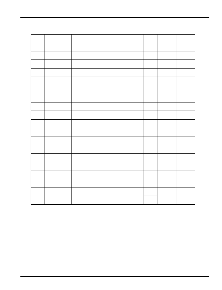
Program Group Parameter Summary
Display Paramete r
TMU
Time Unit
STC
Start C o de
WZ
Wa it Z one
WTM
Wa it Tim e
n.LC
Link Code
n.SP1
n.TS1
n.SP2
n.TS2
...
Program
Start SP
Target SP 1
Segment Time 1
Time Signal 1
On/Off
Target SP 2
Segment Time 2
Time Signal 2
On/Off
...
n.SSP
n.TM1
n.TM2
OFF (0), GEU (0.0% +1 digit to 00.0%)
Setting Range
HH.MM, MM.SS
SSP, P V
OFF (0.00) t o 9 9.59
RST, HOLD, PTN1 , PT N 2
AEU (0.0 to 100.0%)
AEU (0.0 to 100.0%)
OFF, 0.00 to 99.59
ON, OFF
AEU (0.0 to 100.0%)
Time S e t : OFF, 0 . 00 to 99 .59
ON, OFF
...
Unit Default Remark
ABS HH.MM
ABS PV
GEU OFF (0)
TIME OFF (0.00)
ABS RST
AEU AEU (0.0%)
AEU AEU (0.0%)
TIME OFF
ABS OFF
AEU AEU (0.0%)
TIME OFF
ABS OFF
...
...
...
n.SPF
n.TMF
n.TSF
n.RPT
n.REN
n.RST
Target SP 15
Segment Time 15
Time Signal 15
On/Off
Segment Repeat
Repeat En d
Segment
Repeat Start
Segment
AEU (0.0 to 100.0%)
OFF (0), 0.00 t o 9 9.59
ON, OFF
0 to 999 (0 : Infin i t e R epeat )
0, 1 < RST < n.REN < 15(F)
0, 1 < RST < n.REN < 15(F)
29
AEU AEU (0.0%)
TIME OFF
ABS OFF
ABS 1
ABS 0
ABS
0
Page 30
PD550 Series Nova Programmable Process and Temperature Controller Instruction Manual
5.5 Digital Output Group (G.DO)
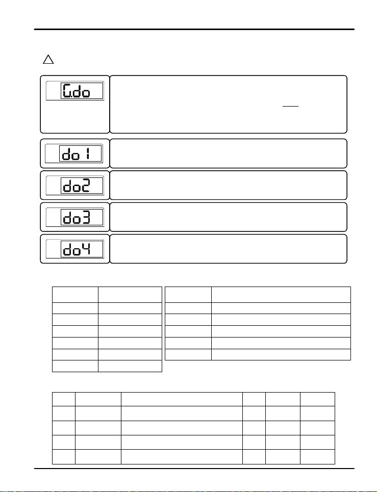
Digital Outputs are an o p t io n a l f e ature . These p a ramete r s a r e o n l y u s e d when appropr iate for a controller with
?
2 or 4 digital outputs as an optional feature
NOTE
PV
Press SET/ENT key to se l e ct t h e d i g it a l o u t p u t g r oup. ( Refer to par ameter map)
ST ST ST ST ST
G.AT Q G.PID Q PWD Q G.CT L Q G.IS Q G.DO
K R
T
G.COM Q G.RET Q G.ALM Q G.OUT Q G.IN
ST
STSTSTST
PV
PV
PV
PV
Table 4 : DO Settings and Functions
DO Setting Function
ALM1
ALM2
ALM3
IS1
IS2
TS
Digital Output Group Parameter Summary
Display Paramete r
DO1
DO2
DO3
DO4
This parameter establish e s t h e f u n ct i o n o f d ig i t a l o u t p u t 1 (DO1 ) . This func t io n s e t s wh a t
conditions will activat e t he out pu t. The settings and funct ions t ha t can be select ed ar e
shown in Table 4 below.
This parameter establish e s t h e f u n ct i o n o f d ig i t a l o u t p u t 2 (DO2 ) . This func t io n s e t s wh a t
conditions will activat e t he out pu t. The settings and funct ions t ha t can be select ed ar e
shown in Table 4 below.
This parameter establish e s t h e f u n ct i o n o f d ig i t a l o u t p u t 3 (DO3 ) . This func t io n s e t s wh a t
conditions will activat e t he out pu t. The settings and funct ions t ha t can be select ed ar e
shown in Table 4 below.
This parameter establish e s t h e f u n ct i o n o f d ig i t a l o u t p u t 4 (DO4 ) . This func t io n s e t s wh a t
conditions will activat e t he out pu t. The settings and funct ions t ha t can be select ed ar e
shown in Table 4 below.
Alarm 1
Alarm 2
Alarm 3
Inner Signal 1
Inner Signal 2
Segment Time Signal
DO1 T ype
DO2 T ype
DO3 T ype
DO4 T ype
ALM1, ALM2, ALM3, IS1, IS2, TS, PEND, UP,
ALM1, ALM2, ALM3, IS1, IS2, TS, PEND, UP,
ALM1, ALM2, ALM3, IS1, IS2, TS, PEND, UP,
ALM1, ALM2, ALM3, IS1, IS2, TS, PEND, UP,
DOWN, SOAK, RUN
DOWN, SOAK, RUN
DOWN, SOAK, RUN
DOWN, SOAK, RUN
DO Setting
PEND
UP
DOWN
SOAK
RUN
Setting Range
Function
Activate when a program ends
Activate d u r i ng a n a s ce n d i n g r a mp se g me n t
Activate d u r i ng a d e s ce n d i n g r a mp se g me n t
Activate during an soak segment
Activate when a progr am is running
Unit Default
ABS OFF
ABS OFF
ABS OFF
ABS OFF
Remark
Option
Option
Option
Option
30
Page 31
PD550 Series Nova Programmable Process and Temperature Controller Instruction Manual
5.6 Inner Signal Group (G.IS)
PV
PV
PV
PV
PV
PV
.
.
.
2.ISH
1.ISH
2.ISL
1.ISL
Press SET/ENT key to select the inner signal group. ( Refer to par ameter map)
ST ST ST ST ST
G.AT Q G.PID Q PWD Q G.CTL Q G.IS Q G.DO
K R
T
G.COM Q G.RET Q G.ALM Q G.OU T Q G.IN
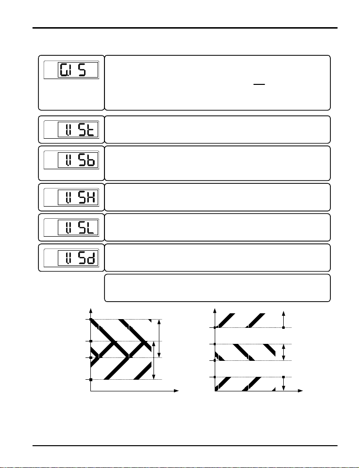
The parameter to set the basis of inner signal activation. The settings are NPV (current
value of the PV), NSP (curren t value of t h e S P), or TSP (tar g e t se t p o i n t o f t h e cu r rent
program segment). Its de f a u l t se t t i n g is N P V.
This parameter set s t h e in n e r signal activation zone to be inside or outside the IS band.
When the value se t i n 1. ISB enters the i nner signal zone, outputs set to inner signal 1 will
activate. The settings are I.BD (in band) and O.BD (out band) where the bands are
determined by t h e values in 1 . ISH and 1.I SL (See Fig 7).
The parameter to e st a b l is h t h e hi g h value for the se t u p o f t h e in n e r signal band.
The paramete r to e st a b l is h t h e l o w value fo r t h e se t u p o f t h e inner signal band.
The parameter to se t t h e i n ne r signal delay. This is the delay time from when the inner
signal activation conditions are met to when the outputs activate.
The parameters used to s e t u p in n e r signal 2 is the same as those used for inner signal 1.
IS 2 Zone
IS 1 Zone
1.ISH
2.ISH
2.ISL
1.ISL
ST
STSTSTST
IS 1 Zone
IS 2 Zone
IS 1 Zone
a) 1.ISB an d 2.ISB are set as I.BD
Fig 7: Inner Sign a l Zones
b) 1.ISB is s e t t o I.BD a n d 2. ISB is set t o O . B D
31
Page 32
PD550 Series Nova Programmable Process and Temperature Controller Instruction Manual
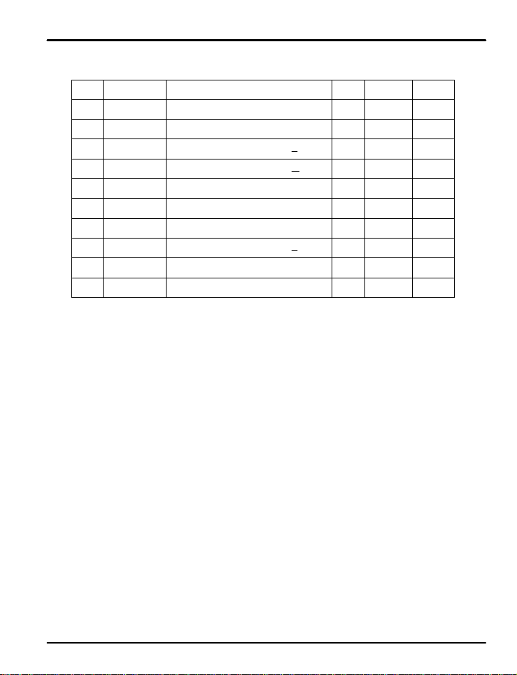
Inner Signal Group Parameter Summary
Display Paramete r
Inner Signal
1.IST
1.ISB
1.ISH
1.ISL
1.ISD
2.IST
2.ISB
2.ISH
2.ISL
2.ISD
Type
Inner Signal
Band Dir e c t io n
Inner Signal
Range High 1
Inner Signal
Range Lo w 1
Inner Signal
Delay Time
Inner Signal
Type
Inner Signal
Band Dir e c t io n
Inner Signal
Range High 2
Inner Signal
Range Lo w 2
Inner Signal
Delay Time
AEU (0.0 t o 100.0 % ) , b u t 1 . ISH > 1.IS L
AEU (0.0 t o 100.0 % ) , b u t 1 . ISH > 1.IS L
AEU (0.0 t o 100.0 % ) , b u t 2 . ISH > 2.IS L
AEU (0.0 to 100.0%), but 2.ISH > 2.ISL
Setting Ra n g e
NPV, NSP, TSP
I.BD (In Band), O.BD (Out Band)
OFF (00.00 ) t o 99.59 ( M M . SS )
NPV, NSP, TSP
I.BD (In Band), O.BD (Out Band)
OFF (00.00) to 99.59 (MM.SS)
Unit Default Remark
ABS NPV
ABS I.BD
AEU AEU (0.0% )
AEU AEU (0.0% )
TIME OFF
ABS NPV
ABS I.BD
AEU AEU (0.0% )
AEU AEU (0.0% )
TIME OFF
32
Page 33
PD550 Series Nova Programmable Process and Temperature Controller Instruction Manual
5.7 PID Group (G.PID)
PV
PV
PV
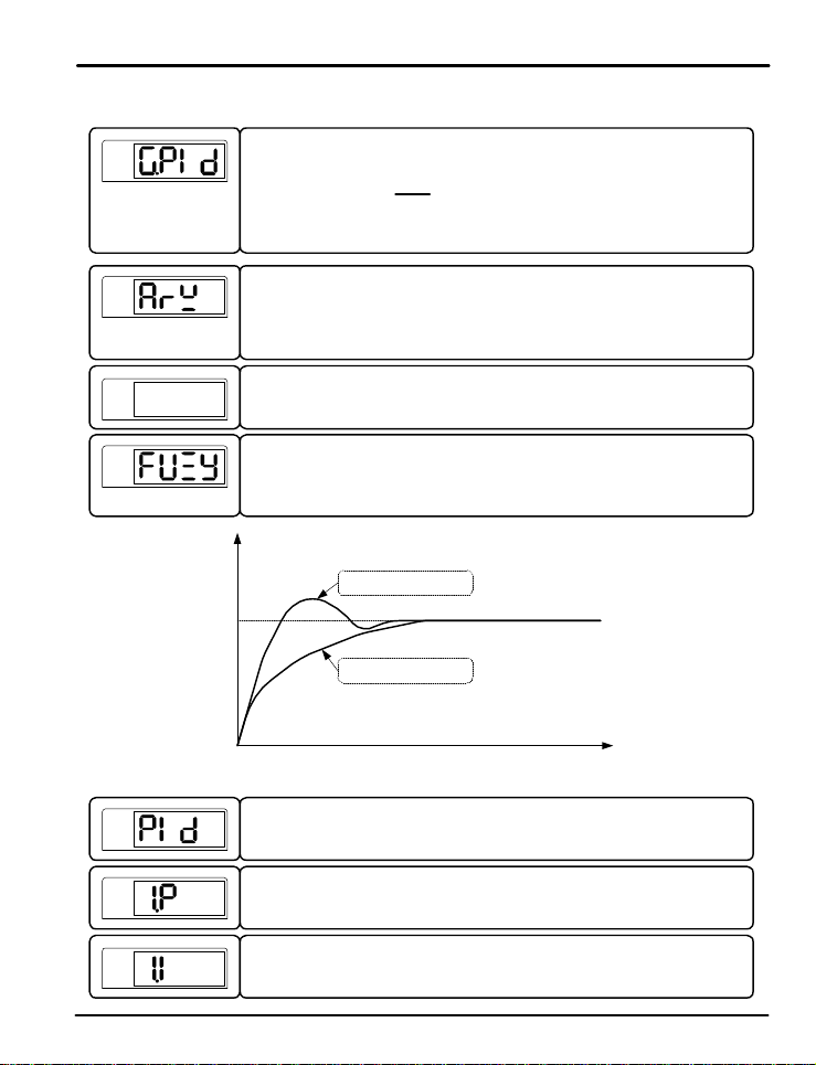
C.mod
PV
Press SET/ENT Key t o se le c t PID G r o u p aft e r pr e ss ¡ã or ¡å Key in Me n u d is p la y
ST
G.AT Q G.PID Q PWD Q G.CT L Q G.IS Q G.DO
K R
T
G.COM Q G.RET Q G.ALM Q G.OUT Q G.IN
The parameter sets the PV deviation width to prevent ov ershoot. When the control outputs
reach this high limit va l u e , t h e y s t o p o r d i n a r y outp u t a c t io n f o r inte g r a l co n t rol and use
ARW (Anti-Reset Windup) . When the setting is AUTO, this parameter is calculated
automatically.
This par a me t e r establishes the c on t rol mode. It can be set to Differential of Deviation Value
(d. dv) or Process Variable (d. pv). Dviation Value mode will reduce ov e r shoo t. Pro cess
Variable mode will more quickly r aise and lower the PV. The default setting is d. d v.
This parameter activa t e s t h e u se o f f u zzy logic. Fuzzy logic can be effective in
suppressing overshoot and reducing PV variation that may occur once the PV has reached
the SP. Refer to Fig 5 : Ove rshoo t S u p p r e ss i o n wi t h F u zzy Logic.
PV: Fuzzy Logic Off
SP
PV: Fuzzy Logic On
Fig 8: Overshoot Suppression with Fuzzy Logic
ST
STST
ST ST
STSTST
ST
PV
PV
PV
This parameter est a b l is h e s t h e n u mb e r o f P ID set t i n g g r o u p s t o b e us e d i n c o n t r o l o u t p u t
calculation. Up to 4 user defined gr oups of proportional, integral, and deriv ativ e value
zones can be established . U s e t h is se t t i n g t o e n t e r t h e se t t i n g menus for each PID gr oup.
The parameter to set th e p r o p o r t i onal operation for PI D control.
Setting range of 1.P is 0.1 to 999.9%.
Its default s e tt i n g i s 1 0 . 0 % .
The parameter to set t h e in t e g ratio n t i me f o r PID c o n t r o l .
Setting ranges of 1.I are O FF or 1 t o 6000 seconds.
Its defau lt s e t t in g i s 1 2 0 s e co n d s
33
Page 34
PD550 Series Nova Programmable Process and Temperature Controller Instruction Manual
PV
PV
.
.
.
PV
PV
PV
PV
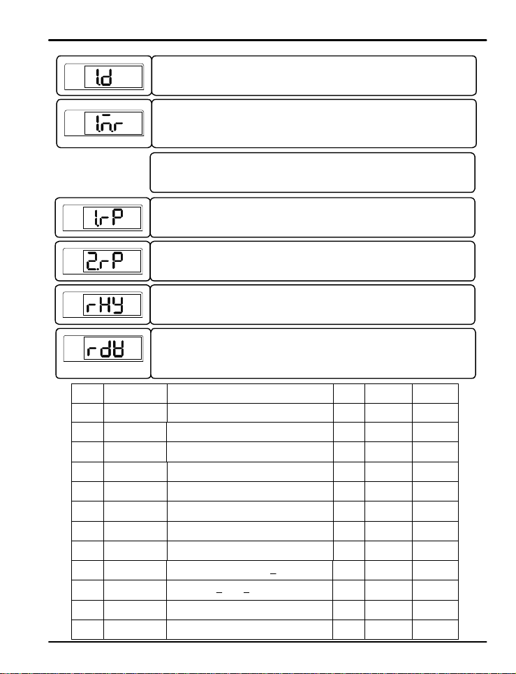
Display Paramete r
Anti-Res e t Win d-
ARW
Up Select
C.MOD Control Mode
FUZY
PID
n.P
n.D
n.MR n.Manual Reset
1.RP
2.RP
RHY
RDV
n.I
n.Derivatio n time
Fuzzy
PID Numb er
n.Proportional
n.Pro/Time
Reference
Point 1
Reference
Point 2
Reference
Hysteresis
Reference
Deviation
The parameter to se t d e r i vation t ime f o r P ID con t rol.
Setting ranges of 1.D a r e OFF o r 1 t o 6000 seconds.
Its default s e t t in g i s 3 0 s e co n d s .
The parameter to set the manual reset in the PID calculation. This setting only functions if
the integral time setting is O F F. T h is se t t i n g a lwa ys fun c t io n s f o r H / C models.
Note: The cont e n t s o f P ID Groups 2, 3, and 4 are the same as PID Group 1.
This parameter establ is h e s t h e P V range of each of the 3 main PID zones. The range of
PID zone 1 is IN.RL (IN.SL if set for mV or V input) to 1.RP. The r ange of PI D zone 2 is
1.RP to 2.RP. The range of PID zone 3 i s 2 . RP to IN.R H (IN . SH i f s e t f o r mV o r V input).
This parameter establ is h e s t h e r a n g e o f e a c h o f t h e 3 ma i n PID zones. The range of PID
zone 1 is IN.RL (IN.SL if set for mV or V input) to 1.RP. T he range of PI D z one 2 is 1.RP
to 2.RP. The range of PID zone 3 is 2 . R P t o IN.R H ( IN.SH if s e t f o r mV o r V in p u t ).
This paramete r e st a b l is h e s t h e h ysteresis wi dt h o f t h e P ID zo n e .
This paramet e r sets th e range o f d e viation f o r P ID zo n e 4 . When t h e d i f f e r e n ce b e t we e n
the PV and SP is greater than this deviation range, the controller will utilize PID group 4
for PID settings. While t h e P V a nd S P a r e wi t h in t h i s d e viation d i f f e r e n c e , t h e co n t r o l l er
will utilize whatever zon e would n or mally b e use d ba sed o n t he PV value .
Setting Ra n g e
Auto or 50.0 to 200.0%
Differential of Deviati on V a l u e ( d . d V ) o r
Process Variabl e ( d . P V )
OFF, ON
MENU (0) or 1, 2 , 3 o r 4
0.1 to 999.9%
OFF, 1 to 6 0 0 0 sec
OFF, 1 to 6 0 0 0 sec
-5.0 to 105.0%
AEU (0.0%) , 1. R P < 2.R P
1.RP < 2.RP < AEU (100.0%)
GEU (0.0 to 10.0%)
GEU (0.0 to 100.0%)
34
Unit Default Remark
% Auto
ABS d. dV
ABS OFF
ABS MENU
% 10.0%
sec 120 sec
sec 30 sec
AEU
AEU
For Use
When I=0
PID Zon e 1
PID Zon e 2
% 50.0%
AEU
(100.0%)
AEU
(100.0%)
GEU AEU (0.3%) PID Zone 3
GEU AEU (0.0%) PID Zone 4
Page 35
PD550 Series Nova Programmable Process and Temperature Controller Instruction Manual
5.8 Aut o -Tuning Group (G.AT)
PV
PV
?
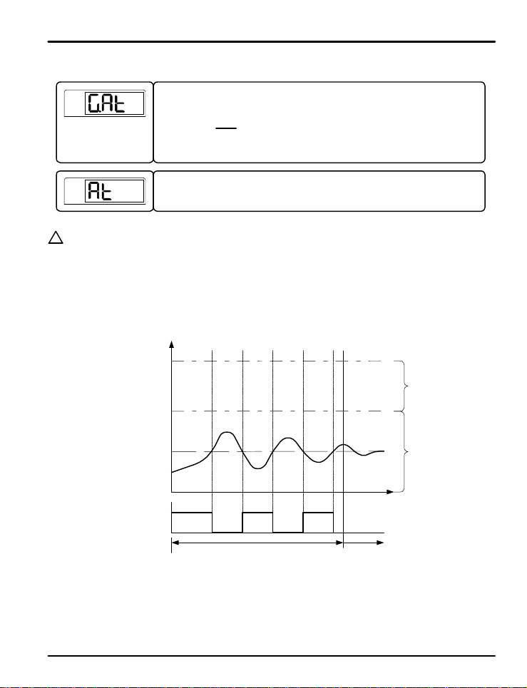
AUTO-TUNING (AT)
NOTE
The auto-tuning feature is u se d t o l e t t h e co n t r o l l er measu r e p rocess ch a racte r i s t ic s a n d a u t o ma t ic a ll y s e t t h e mo st
appropriate values for the PID pa r a me t e r s . D u r i n g t h e d e f a u lt a u t o - t u n i n g p r o c e ss , t h e co n t r o l o u t p u t s wi ll
function in an On/Off mode, and the controller will use the r e sponses to calculate the needed PID values. During
this setup proce s s, t h e A T LED on t h e co n t r o l l er will blink.
Start the auto-tuning process while th e co n t r o l l e r i s ma in t a i n in g a s e t p o in t , e i t h e r wh i le r unning a progr am, or while
in HOLD mode. Auto-tuning will set the PI D p ar amete rs f or th e PI D z one which the set point is in, based on the
PID reference poin t (RP) e n t e r e d .
Press SET/ENT key to select t h e a u t o - t u n i n g g r oup. ( Refer to par ameter map)
ST
G.AT Q G.PID Q PWD Q G.CT L Q G.IS Q G.DO
K R
T
G.COM Q G.RET Q G.ALM Q G.OUT Q G.IN
The parameter to activate t h e a u t o - t u n in g f u n c t io n . Whe n AT is set to O N , a u t o -tuni n g wi ll
begin, indicated by the AT ligh t b l in k in g . This para me t e r c annot be used if the controller
does not have an a ct i ve set poi n t , e it h e r fro m r unning a progr am, or being in HOLD mode.
ST
STST
ST ST
STSTST
RH
RP
SP
RL
ST
2.PID
1.PID
ON OFF ON OFF ONControl Output
Auto-Tu n in g On
(On/Off Operation, M A N L E D B li n ki n g )
Fig 9: Auto-Tuning
35
PID Contro l
Page 36
PD550 Series Nova Programmable Process and Temperature Controller Instruction Manual
Display During Auto-Tuning:
The AT LED on the front panel will blink at a 500 ms time interval.
Changing the Set Point During Auto-Tuning:
If the set point is changed during the auto-tuning process, the original set point will be maintained for the
duration of the auto-t u n in g p r o c e ss . A f t e r a u t o - t u n i n g is co mp l et e , t h e c o n t r o l le r will change to the new set
point.
Changing PID Parameters During Auto-Tuning:
The PID values can be changed during the auto-tuning process. After auto-tuning is complete, it will then use
the auto-tune calculated PI D values. Va l u e s c hanged after auto- tuning will remain set u nt il aut o- t unin g is r un
again.
Auto-Tuning Interruption s o r E r rors :
The auto-tunin g p r o c e ss will en d witho ut e ff ect for a ny of th e fo llowing r e ason s:
- Auto-tuning forced t o end ( Ex ample: Controller power down or stop condition)
- Open sensor (S.OPN) input error d e t e ct e d d u r i n g t h e a u t o - t u n in g p roces s
- Auto-tuning cycle exceeds 24 hours.
- Control changed to manual (MAN) operation during auto-tuning.
PV
PID Group Parameter Summary
Display Parameter
AT
AT-G
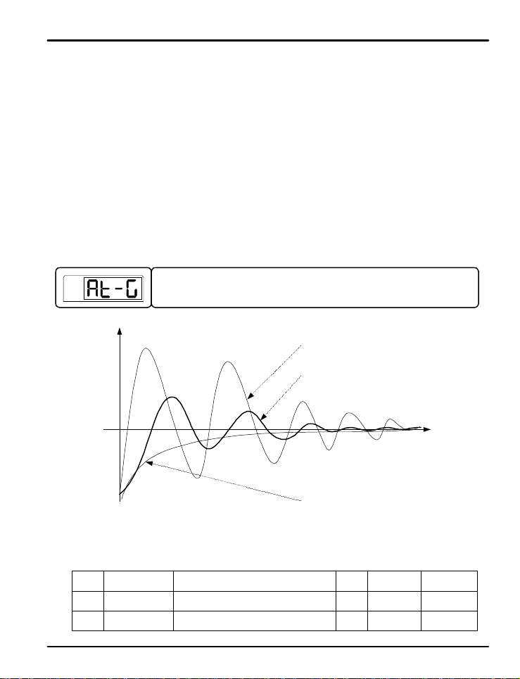
This parameter effe ct s t h e p r o p o r t i o n a l value de r i ved by au t o -tuni n g . R e d u ce t h e A T-G
gain value and the cycle becomes more rapid, but more unstable. Increasing gain slows
system react ion time, b ut sy ste m stabilit y incr ea ses.
Auto Tuning
AT Ga i n
Fig 10: Auto-Tuning G ain
Setting Range
OFF, ON
0.1 to 10.0
36
Gain < 1
Gain = 1
Gain > 1
Unit Default Remark
ABS OFF
ABS 1.0 Gain Value
Auto-Tune
Activation
Page 37
PD550 Series Nova Programmable Process and Temperature Controller Instruction Manual
5.9 Alarm Group (G. A L M )
PV
PV
PV
PV
PV
PV
PV
.
.
.
?
Alarm Types and LED Display
NOTE
SP
AH.FS
Press SET/ENT key to sele ct t h e a l a r m g r o u p . (Refe r to p a r a me t e r ma p in s e ct i o n 3 . )
ST
G.AT Q G.PID Q PWD Q G.CTL Q G.IS Q G.DO
K R
T
G.COM Q G.RET Q G.ALM Q G.OUT Q G.IN
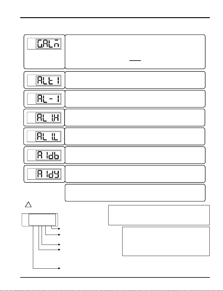
The parameter to set the type of alarm to be set for alarm 1.
The types o f al a r ms se l e ct a b l e a r e s h ow n i n Table 3: A l a r m Se l e c t io n .
The parameter to set th e a la rm trig g e r poin t f o r t h e a l a r m se t i n A LT1.
This parameter dis p la ys if a h ig h , l o w, o r h i g h and low limit alarm was selected for ALT1.
This establishes the high deviation range to tr igger the alarm of deviation. T his parameter
displays if a deviation alarm was selected in ALT1.
This establishes the low deviation range to trigger the alarm of deviation. This parameter
displays if a deviation alarm was selected in ALT1.
The paramete r to se t t h e dead band (H ysteresis) of alarm 1.
The parameter to se t t h e d e la y time b e f o r e o f a l a r m 1 i s t r i g g e r e d .
Note: The menus for alarm 2 and 3 are the same as alarm 1.
S indicates standby operation
F for forward operation
r for reverse (failsafe) operation
Decimal point always display e d
H indicates a high alarm
L indicates a low alarm
o for outside range of deviation band
I for inside range of dev iation band
A indicates an absolute value alarm
d indicates a deviation alarm
ST
STST
Alarm Output Settings:
- Forwar d: Relay ene r g i z e d i n a l arm condition
- Reve r s e: Failsafe operation. Relay energized during normal
ST ST
operatin g conditions
Standb y Operation:
The alarm will not trigger if the alarm condition
occurs during the f o ll o win g a c t ivities.. .
- during power-up
- the set point is changed
- the type of alarm is changed
STSTST
ST
37
Page 38
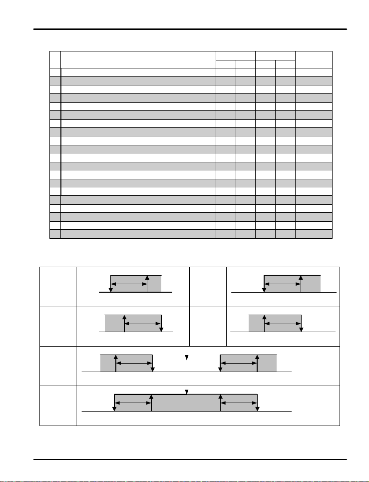
PD550 Series Nova Programmable Process and Temperature Controller Instruction Manual
Table 3: Alarm Selection
No. Alarm Type
1
Absolute V a lu e H i g h L imi t Al a r m
2
Absolute Value Low Limit Alar m
3
High Limit Dev i a t i on A l a r m
4
Low Limit Deviation Alarm
5
High Limit Dev i a t i on A l a r m
6
Low Limit Deviation Alarm
High and Low Limit Deviation Alarm7
High and Low L imi t R a n g e D e viation Al a r m8
9
Absolute V a lu e H i g h L imi t Al a r m
10
Absolute Value Low Limit Alar m
11
Absolute Value High Limit Alarm with Standby
12
Absolute Value Low Limit Alarm with Standby
13
High Limit Deviation Alarm with Standby
14
Low Limit Deviation Alarm with Standby
15
High Limit Deviation Alarm with Standby
16
Low Limit Deviation Alarm with Standby
17
High and Low Limit Deviation Alarm with Standby
18
High and Low Limi t R a n ge Dev i a t io n A la rmwith S tandb y
19
Absolute Va lu e H i g h L imi t A l a r m wit h S tandby
20
Absolute Value Low Limit Alarm with Standby
Operation
For
3
3
3
3
3
3
3
3
3
3
3
3
Rev
Standby
On
3
3
3
3
3
3
3
3
3
3
3
3
3
3
3
3
3
3
Off
3
3
3
3
3
3
3
3
3
3
Display Dat a
AH.F
AL.F
DH.F
DL.F
DH.R
DL.R
DO.F
DI.F
AH.R
AL.R
AH.FS
AL.FS
DH.FS
DL.FS
DH.RS
DL.RS
DO.FS
DI.FS
AH.RS
AL.RS
PV High
Limit Alarm
PV L ow
Limit Alarm
High and Low
Limit D evi a t i o n
Alarm
High and Low
Limit Range
Deviation
Alarm
DEV
-
DEV
-
PV
PV
W OFF
W ON
ALM.L
W OFF
W ON
ALM
S
ONX
DB
S
ALM
DB
S
OFFX
DB
OFFX
ONX
DB
S
ALM.L
Fig 11: Ala r m Operatio n
DEV=0
U
SP
DEV=0
U
SP
38
High Limit
Deviation
Alarm
Low Limit
Deviation
Alarm
W OFF
W ON
ALM.H
DEV
U
-
W OFF
SP
W ON
DEV
USPS
- +
ALM.L
ONX
DB
S
ALM.H
DB
S
OFFX
ONX
DB
S
ALM.H
DB
OFFX
+
+
+
Page 39
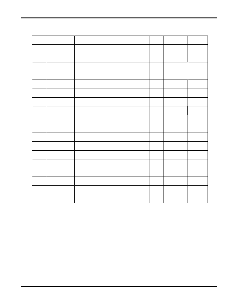
PD550 Series Nova Programmable Process and Temperature Controller Instruction Manual
Alarm Group Parameter Summary
Display Paramete r
ALT1
Alarm Type 1 Refer t o Ta b l e 5: Alarm Sele ct i o n ABS AH.F
AL-1
Set valu e of ALT1
High Deviation
AL1.H
Limit of Alarm 1
Low Deviatio n
AL1.L
Limit of Alarm 1
A1DB
Alarm 1 DB
Delay Time of
A1DY
ALT2
AL-2
AL2.H
AL2.L
A2DB
A2DY
ALT3
AL-3
AL3.H
AL3.L
A3DB
A3DY
Alarm 1
Alarm Type 2 Refer to T a b l e 5 : A l a r m S e le c t io n AB S AH.F
Set v a lue of
ALT2
High Deviation
Limit of Alarm 2
Low Deviatio n
Limit of Alarm 2
Alarm 2 DB
Delay Time of
Alarm 2
Alarm Type 3 Refer to (Ta b l e 5 : Al a r m S e le c t i on ) ABS AH.F
Set v a lue of
ALT3
High Deviation
Limit of Alarm 3
Low Deviatio n
Limit of Alarm 3
Alarm 3 DB
Delay Time of
Alarm 3
Setting Ra n g e
AEU (-10 0 . 0 t o 1 0 0 . 0 %)
GEU (-100.0 to 100.0%)
GEU (-100.0 to 100.0%)
GEU (0.0 to 100.0%)
0.00 to 99. 5 9
AEU (-100.0 to 100.0%)
GEU (-100.0 to 100.0%)
GEU (-100.0 to 100.0%)
GEU (0.0 to 100.0%)
0.00 to 99.59
AEU (-100.0 to 100.0%)
GEU (-100.0 to 100.0%)
GEU (-100.0 to 100.0%)
GEU (0.0 to 100.0%)
0.00 to 99.59
Unit Default Remark
AEU AEU (100.0%)
GEU GEU (0.0%)
GEU GEU (0.0%)
GEU GEU (0.5%)
MM.SS 0.00
AEU AEU (100.0%)
GEU GEU (0.0%)
GEU GEU (0.0%)
GEU GEU (0.5%)
MM.SS 0.00
AEU AEU (100.0%)
GEU GEU (0.0%)
GEU GEU (0.0%)
GEU GEU (0.5%)
MM.SS 0.00
Absolut e
Value Alarm
Deviation
Alarm
Deviation
Alarm
Absolut e
Value Alarm
Deviation
Alarm
Deviation
Alarm
Absolut e
Value Alarm
Deviation
Alarm
Deviation
Alarm
39
Page 40
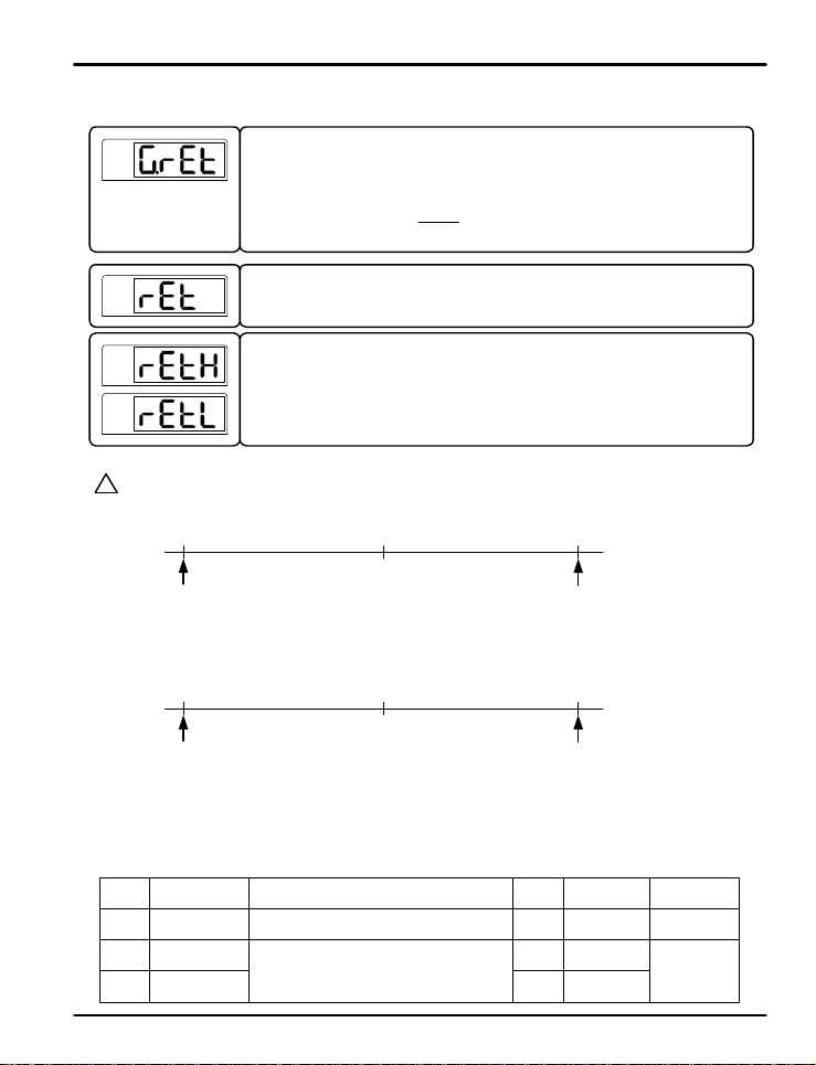
PD550 Series Nova Programmable Process and Temperature Controller Instruction Manual
5.10 Retransmission Group (G.RET)
PV
PV
PV
PV
PV and SP Type Retr a n s missio n S c a l e
?
PV type retransmits based on the input value, SP retransmits based on the set point value.
NOTE
4.0 mA
RETL
MV Type Retransmission Scale
MV type retr a n smi t s b a s e d o n t h e f ul l sc a le o u t p u t a n d wh a t is cu rren t ly bein g t ransmit t e d b y the co n t r o l o u t p u t s
4.0 mA
0.0%
(No Output )
Press SET/ENT key to se l e ct t h e retr a n smi ss io n g roup. (Ref e r t o p a r a me t e r ma p )
ST
G.AT Q G.PID Q PWD Q G.CTL Q G.IS Q G.DO
K R
T
G.COM Q G.RET Q G.ALM Q G.OUT Q G.IN
This parameter sets t h e t y p e o f r e t ransmis s io n u s ed . The opti o n s a re PV, SP , M V , o r
LPS. See notes below for an explanation of the retransmission type s .
Its default s e t t in g i s P V .
These parameter s a r e u s ed t o s ca l e t h e r e t ransmit t i n g o u t p u t . They s e t t h e h ig h a n d l o w
limits for the ret r a n s mis si o n o ut p u t s ca l e , a s s h o wn b e lo w. The ret r a n smi t t in g o u t p u t s wil l
transmit 4 mA at the low limit (RETL) and 20 mA at the high limit (RETH ) values. These
limits are u se d when the r etransmission type is set to PV or SP.
ST
STST
ST ST
12.0 mA
STSTST
20.0 mA
RETH
12.0 mA
20.0 mA
100.0%
(Maximum Output)
ST
LPS Type Retransmission
LPS (Loop Power Suppy) retransmitting outputs will transmit a 14-18 VD C @ 2 0 mA power sup ply ou tp ut.
Retransmission Group P a r a mete r S u mmary
Display Paramete r
RET
Select Ret Type
RETL
Ret Sc al e
High Limit
Ret Sc al e
Low Limit
RETH
Setting Range
PV, SP, MV, LP S
T/C, RTD: INRH to INR L
mV, V: INSH to INSL
RETH > RETL
Unit Default Remar k
ABS PV
AEU INRH Only Valid when
AEU INRL
40
RET is Set t o
PV or SP
Page 41
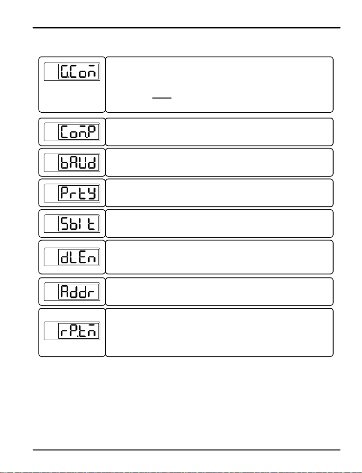
PD550 Series Nova Programmable Process and Temperature Controller Instruction Manual
5.11 Communication Group (G.COM)
PV
PV
PV
PV
PV
PV
PV
PV
Press SET/ENT ke y t o s e le c t t h e co mmu n ic a t io n g roup. (Refer to parameter map)
ST
G.AT Q G.PID Q PWD Q G.CTL Q G.IS Q G.DO
K R
T
G.COM Q G.RET Q G.ALM Q G.OUT Q G.IN
ST
STST
ST ST
STSTST
ST
The parameter to select the type of communication protocol to be used.
The parameter to set the communication speed (baud rate).
The baud rate can be set at 600 to 19200 bps (bytes per second).
The default se t t i n g is f o r 9600 bps.
The parameter to set communication parity.
This can be set to NONE, EVEN, or O DD.
The default setti n g is N O N E .
The parameter to set the communication stop bit.
This can b e s e t a s 1 o r 2 .
It is initially set as 1.
The parameter to set the communication data length.
This can be set t o 7 o r 8. The d e f au l t s e t t in g i s 8 .
This parameter is not d is p la yed when the communication protocol (COM.P) is set for
MODBUS ASCIII or RTU.
The paramete r to se t t h e c o mmun i ca t i o n a d dress f o r t h e co n t rolle r .
This can b e s e t a s 1 t o 9 9 p cs address.
Its default s e tt i n g i s 1 .
The parameter to set communication response time.
The RP.TM is the dela y t o return dat a t o t h e u p p e r l e vel dev i ce a f t e r pro ce s si n g
commands received from the upper lev el device.
The setting RP.TM i s b a s e d o n t h e nu mb e r of 10 ms in t e r vals to d e la y (example: a s e t t in g
of 2 will result in a 2 0 ms d e la y). If RP.T M is se t t o 0 i t will immediately r e tur n a r esponse
once the command processing is complete.
41
Page 42
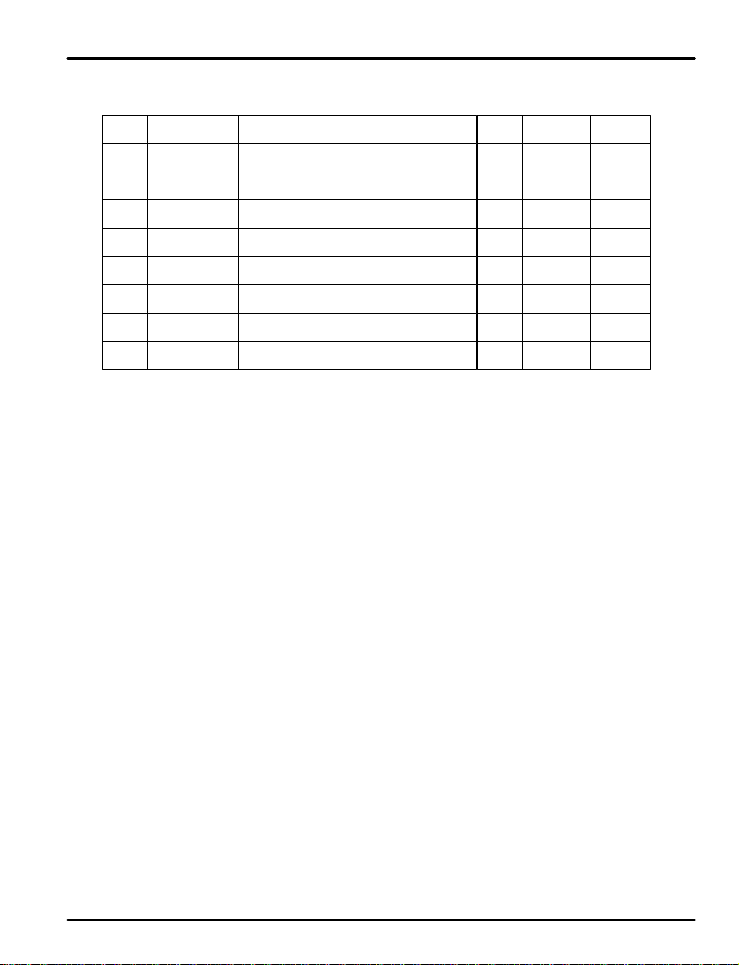
PD550 Series Nova Programmable Process and Temperature Controller Instruction Manual
Communication Group Parameter Summary
Display Paramete r
Communication
COM.P
BAUD
PRTY
SBIT
DLEN
ADDR
RP.TM Response Time
Protocol
Baud Rate 600, 1200, 2400, 4800 , 9600, 1 9 2 0 0 ABS 9600 Option
Parity
Stop Bit
Data Length
Address
1 to 99 (maximum of 31 connected at on c e )
Setting Range
PCC0, PCC1, Modbus ASCII,
Modbus RTU, Sync-Master,
Sync - Sla ve
None, Even, Odd
1, 2
7, 8 (not used when set for MODBUS)
0 to 10 (number of 10 ms intervals)
Unit Default Remark
ABS PCC0 Option
ABS None Option
ABS 1 Option
ABS 8 Option
ABS 1 Option
ABS 0 Option
42
Page 43
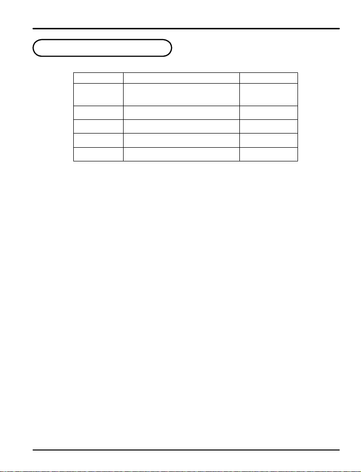
PD550 Series Nova Programmable Process and Temperature Controller Instruction Manual
6. Error Display and Correcti o n
Error Message Action Needed
E.SY S Needs Re p a ir
E.RJC Needs R e p a ir
SP Decimal
Flashing
S.OPN Check Sensor
E.AT Check Process
Auto-Tune Timed Ou t (Over 2 4 H o u r s )
Error In c i dent
EEPROM, DAT A L o s s
RJC SENSOR Failure
Communication Failure
Open Sensor Detected
Check Comm Cable
43
Page 44
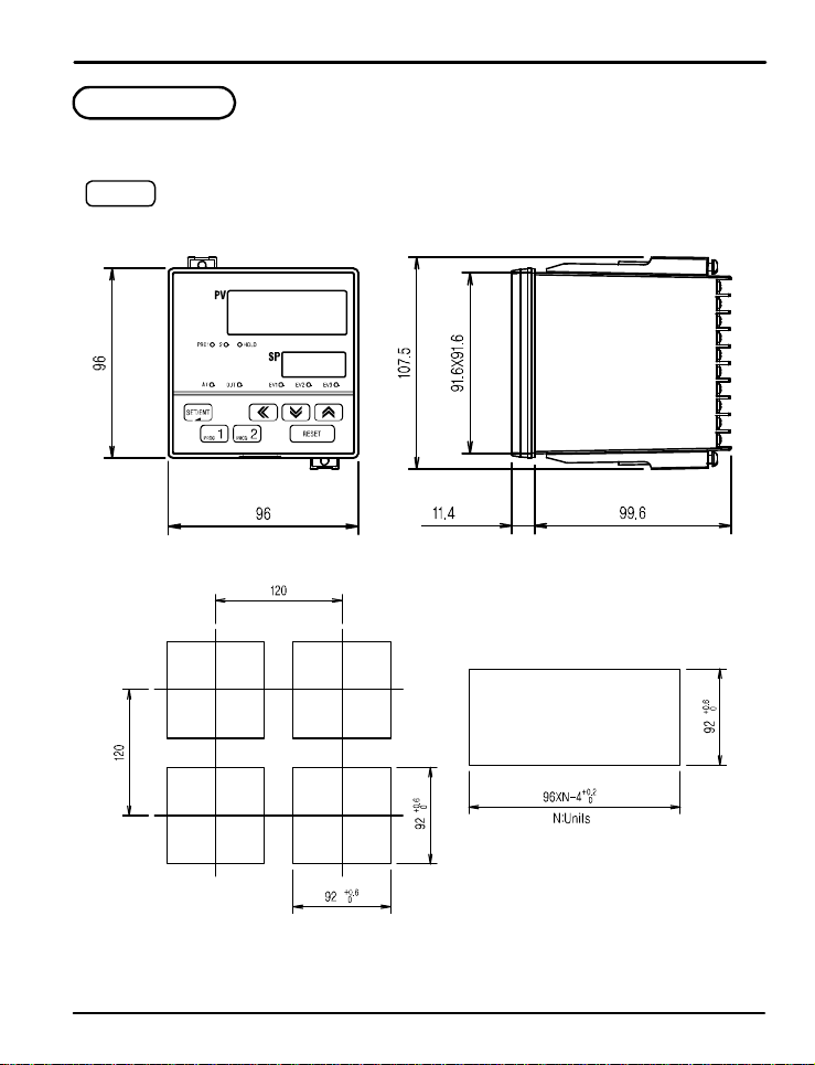
PD550 Series Nova Programmable Process and Temperature Controller Instruction Manual
7. Installation
7.1 Dimensions and Panel Cutouts
PD558
1/4 DIN
(3.78)
(4.23)
(3.61x3.61)
(3.78) (0.45)
(4.72)
(4.72)
(3. 62)
(3.62)
m
Units: m
(3.92)
(3.62)
(3.78XN)
(inch) - for reference on ly
44
Page 45
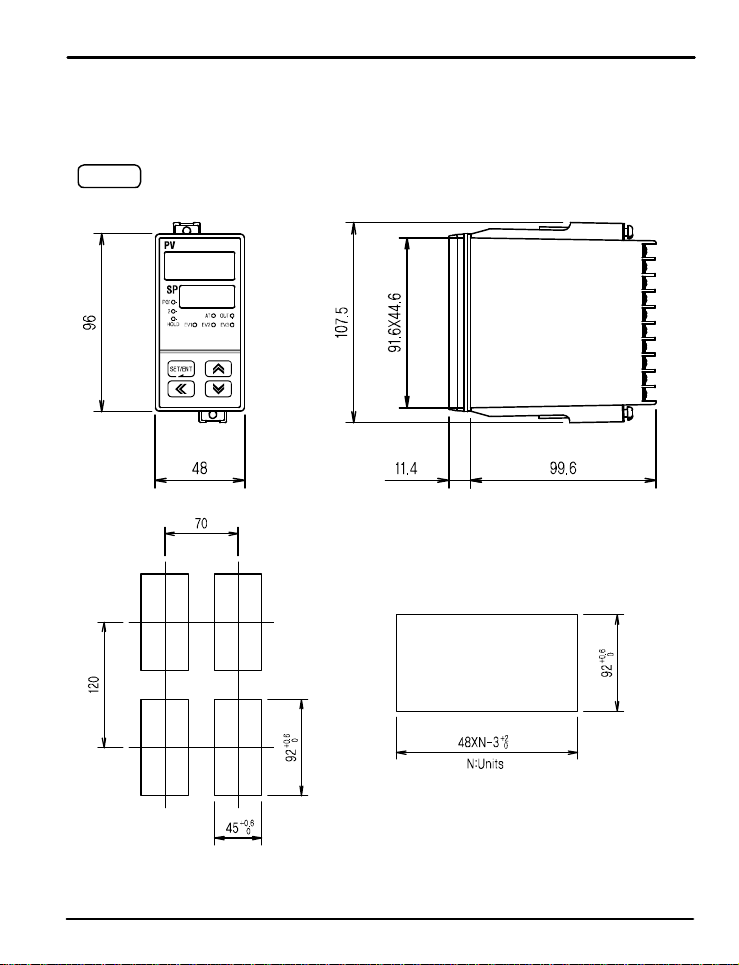
PD550 Series Nova Programmable Process and Temperature Controller Instruction Manual
PD556
1/8 (V) DIN
(3.78)
(4.72)
(1.89)
(2.76)
(1.77)
(4.23)
(3.61X1.76)
(0.45) (3.92)
(3.62)
(3.62)
(1.89XN)
Units: m
m
(inch) - for reference on ly
45
Page 46
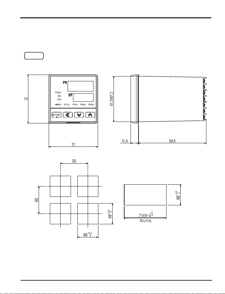
PD550 Series Nova Programmable Process and Temperature Controller Instruction Manual
PD554
3/16 DIN
(2.83)
(3.54)
(2.83)
(3.54)
(2.68)
(2.65X2.65)
(0.45) (3.92)
(2.68)
(2.80XN)
m
Units: m
(inch) - for reference on ly
(2.68)
46
Page 47
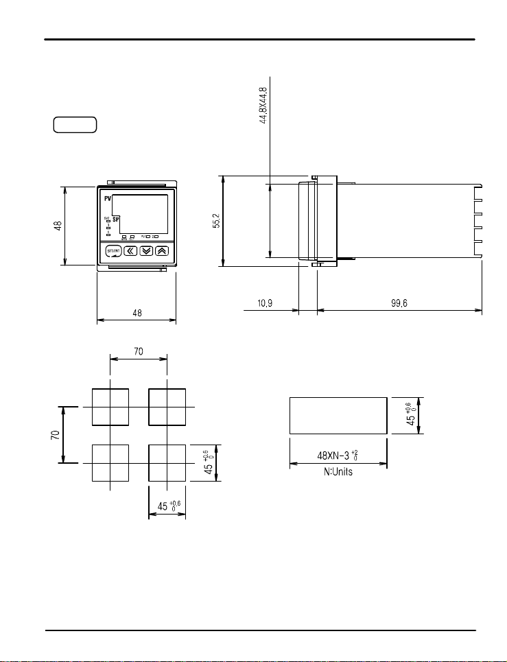
PD550 Series Nova Programmable Process and Temperature Controller Instruction Manual
PD550
1/16 D I N
(1.89)
(2.76)
(1. 76X1.76)
(2.17)
(0.43) (3.92)
(1.89)
(2.76)
(1.77)
(1.77)
(1.89XN)
(1.77)
m
Units: m
(inch) - for reference on ly
47
Page 48
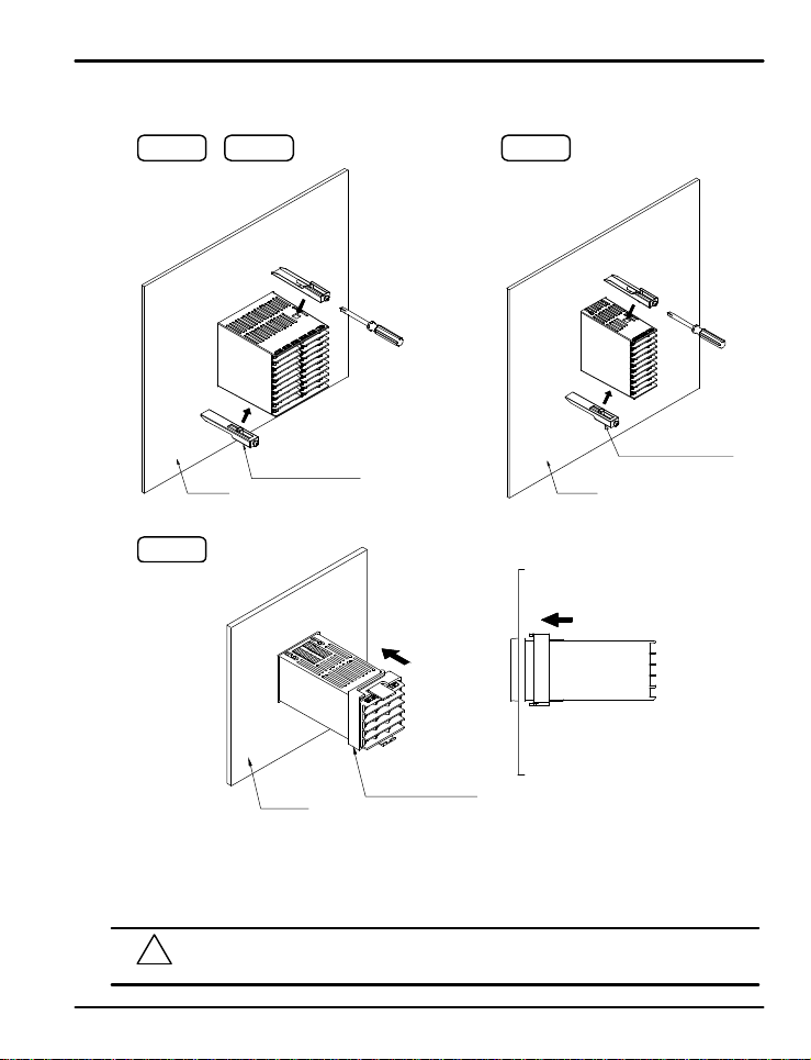
PD550 Series Nova Programmable Process and Temperature Controller Instruction Manual
7.2 Panel Mounting
PD558 PD554
Mount ing Br ack et
Panel
PD550
PD556
Mounting Bracket
Panel
Panel
Installation Steps
1. Cut the mounting panel. (Refer to 7.1 Dimens io n s a nd Pan e l Cu t o u t s)
2 . Insert the controlle r through the front o f t he panel rear terminals first.
3. On applicable models, attach the right an d le f t mo u n t in g b racket an d secu r e it t o t h e pane l.
4. On 1/16 DIN controller models, slide the mounting bracket onto the back of the controller as shown, and slide it
forward on the cont r o l le r unt il t h e b r a ck e t l ocks in pla ce, and th e con tr olle r is secur e .
Do not excessively tighten the mounting bracket screws. Excessive tightening may lead to
!
CAUTION
controller or p a n e l d a ma g e .
Mounting Bracket
48
Page 49
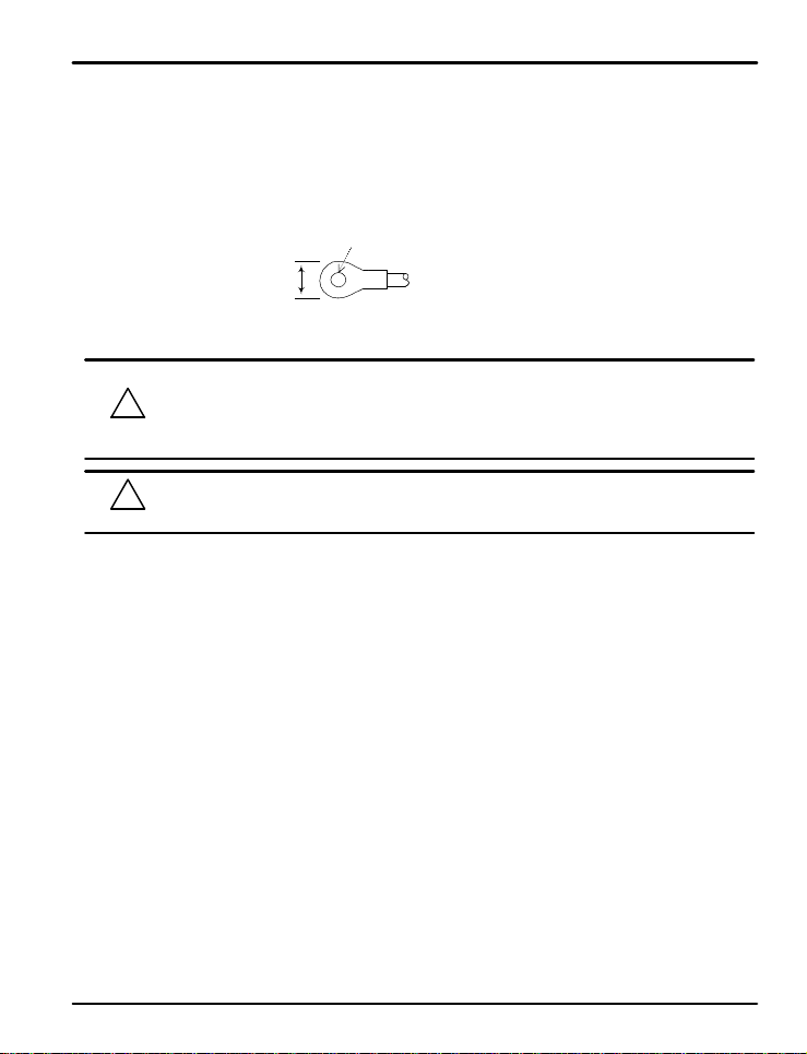
PD550 Series Nova Programmable Process and Temperature Controller Instruction Manual
7.3 P o w e r Cable Specificati on
Make power connections using 0.9 to 2.0 mm2 or 16 AWG vinyl insulated wire. (Voltage rating of 300 VAC)
7.4 Terminal Specificati on
Use M3.5 scr e w- c o mpa t i b le c r i mp o n t e rminals wit h i n su l at i n g sl e e ve as shown be l o w.
Minimum Diameter
3.0 mm
(0.118 in )
Maxi mu m
Measurement
Use copper conductors only if the terminal is for connection to copper wire only.
Always turn off t h e so u rce cir c u it b reake r and check to ensure the power is off to the controller through the
use of a tester p rior t o wo rking o n t h e wi r i n g t e r min a l s.
!
CAUTION
!
CAUTION
z Never touch the terminals in the rear panel when power is supplied to the controller.
z Be sure to tur n o f f th e electric power b e f o re wiring an y ter min a l s.
Bind the wires connected to the controller terminals neatly together in order to
prevent el e ct r o magnetic interference.
5.8 m m
(0.228 in)
Note: Inch e s f o r ref e r e n c e o n l y.
49
Page 50
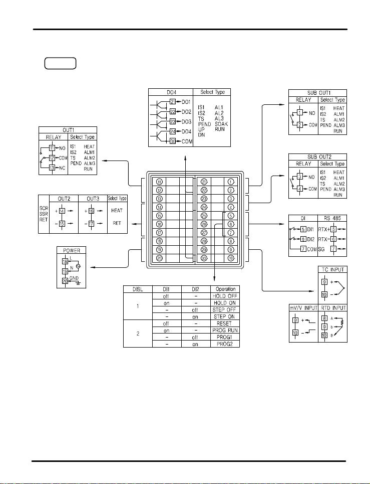
PD550 Series Nova Programmable Process and Temperature Controller Instruction Manual
7.5 Terminal Assignment , Connecti on s , an d Ratings
PD558
Transist o r R a t i ng : 2 4 VD C @ 5 0 mA max
Rating: 250 VAC @ 3 A
30 VDC @ 3 A
4 - 20 mADC or 15 VDC Voltage Pulse
100 - 240 VAC 50/60 Hz
Rating: 25 0 VA C @ 1 A
30 VDC @ 1 A
Rating: 25 0 VA C @ 1 A
30 VDC @ 1 A
-
Max: 19200 b p s
Open circuit voltage:
approximat e ly 5 VDC
Logic le v e ls :
Lo = 0 to 0.8 VDC
Hi = 4.7 t o 28 VDC
NO switches (external excitation not required) or open collector transistor
50
Page 51
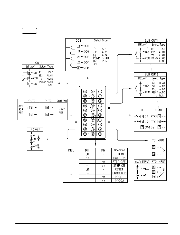
PD550 Series Nova Programmable Process and Temperature Controller Instruction Manual
PD556
Transist o r R a t i ng : 2 4 VD C @ 5 0 mA max
Rating: 250 VAC @ 3 A
30 VDC @ 3 A
4 - 20 mADC or 15 VDC Voltage Pulse
Rating: 250 VAC @ 1 A
30 VDC @ 1 A
Rating: 250 VAC @ 1 A
30 VDC @ 1 A
-
Max: 19200 b p s
100 - 240 VAC 50/60 Hz
Open circuit voltage:
approximat e ly 5 VDC
Lo = 0 to 0.8 VDC
Hi = 4.7 t o 28 VDC
Logic le v e ls :
NO switches (external excitation not required) or open collector transistor
51
Page 52
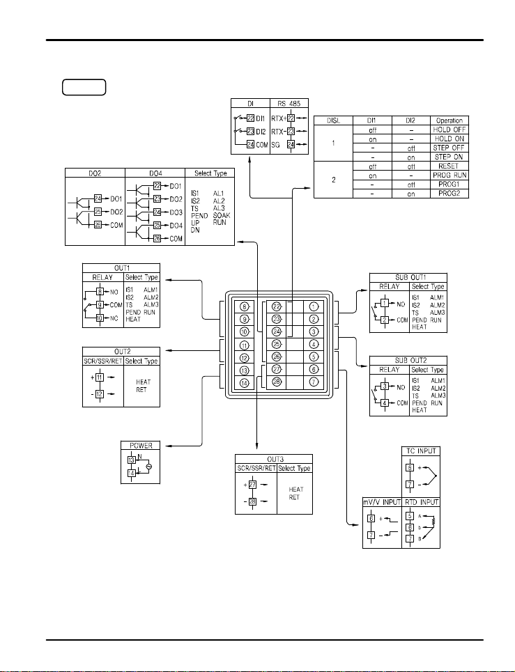
PD550 Series Nova Programmable Process and Temperature Controller Instruction Manual
PD554
Transist o r R a t i ng : 2 4 VD C @ 5 0 mA max
Rating: 250 VAC @ 3 A
30 VDC @ 3 A
4 - 20 mADC or 15 VDC Voltage Pulse
-
Max: 19200 b p s
Logic le v e ls :
Open circuit voltage:
approximat e ly 5 VDC
NO switches (exte r n a l e xcitation n o t requi r e d )
or open collector transistor
Rating: 250 VAC @ 1 A
Rating: 250 VAC @ 1 A
Lo = 0 to 0.8 VDC
Hi = 4.7 t o 28 VDC
30 VDC @ 1 A
30 VDC @ 1 A
100 - 240 VAC 50/60 Hz
4 - 20 mADC or 15 VDC Voltage Pulse
52
Page 53
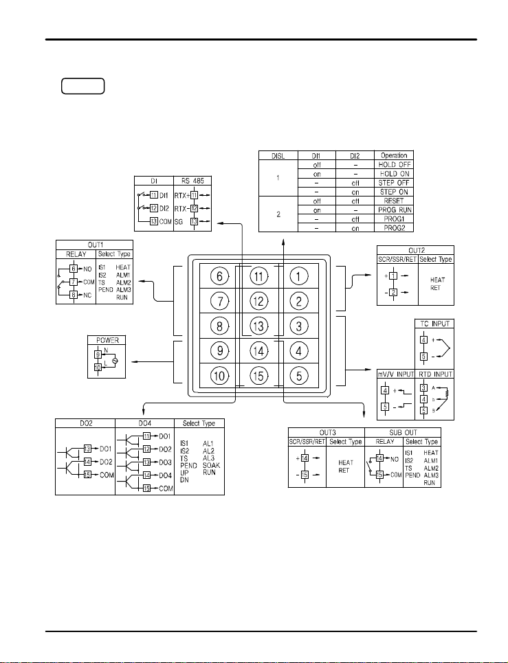
PD550 Series Nova Programmable Process and Temperature Controller Instruction Manual
PD550
Rating: 250 VAC @ 3 A
30 VDC @ 3 A
100 - 240 VAC 50/60 Hz
Transist o r R a t i ng : 2 4 VD C @ 5 0 mA max
-
Max: 19200 b p s
NO switches (external excitation not required) or open collector transistor
Open circuit voltage:
approximat e ly 5 VDC
Logic le v e ls :
Lo = 0 to 0.8 VDC
Hi = 4.7 t o 28 VDC
4 - 20 mADC or 15 VD C V o l t a ge P u l se
Rating:
250 VAC @ 1 A
30 VDC @ 1 A
4 - 20 mADC or
15 VDC Voltag e Pulse
53
Page 54
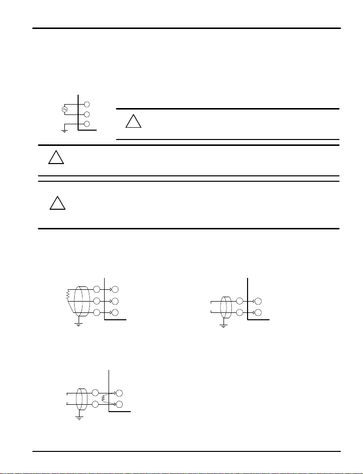
PD550 Series Nova Programmable Process and Temperature Controller Instruction Manual
7.6 Grounding and Power Cable Connection
Use a th ic k g rounding cable of at least 2 mm2 or 14 AWG and shorter than 20 m (approximately 22 ft) for class-3
grounding or better with a gr o u nd i n g r e s is t a n ce o f l e ss t han 100 Ω .
Be sure to ground from the grounding terminal to an independent grounding point. (1 point grounding)
Use 0.9 to 2.0 mm2 or 1 6 A WG vinyl insu l a t e d wire (Voltage rating 300 V A C ) o r t h i c ke r f o r powe r ca b l e co n n e c t io n .
L
!
CAUTION
!
CAUTION
N
FG
CAUTION
To prevent electric shock, b e su r e t o t u rn off p o we r to t h e Nov a C o n t r o l le r and t he s o u r c e ci r c u it b reake r
before wir i n g .
Be sure to connect t o co rrec t p ol a r i t i e s. C o n n e cting t o a wr o n g p o la rity ma y c a u se d a mage or malfunction.
Use shielded wires a n d g r o und the shielding to an independent grounding point.
Keep the input signal and output wiring as far as possible away from the power and ground circuit.
Use a wire with low conductive resistance and no three-wire resistance differential.
Be sure to connect L (Hot), N (neutral), and GND (gr ound) as indicated.
!
Failure to wire th e po we r and ground as indicated could result in damage
to the controller.
7.7 Signal Input Connection
(1) RTD Input (2) DC Voltage Input
SHIELD
A
b
RTD
INPUT
B
NOVA
V
SHIELD
+
INPUT
NOVA
(3) DC Current Input
SHIELD
DCmA R
To accept a 4-20 mA s ignal, select 0.4 to 2.0 VDC input and
connect a 100 Ω resistor across t h e i nput terminals as shown.
+
-
INPUT
NOVA
54
Page 55
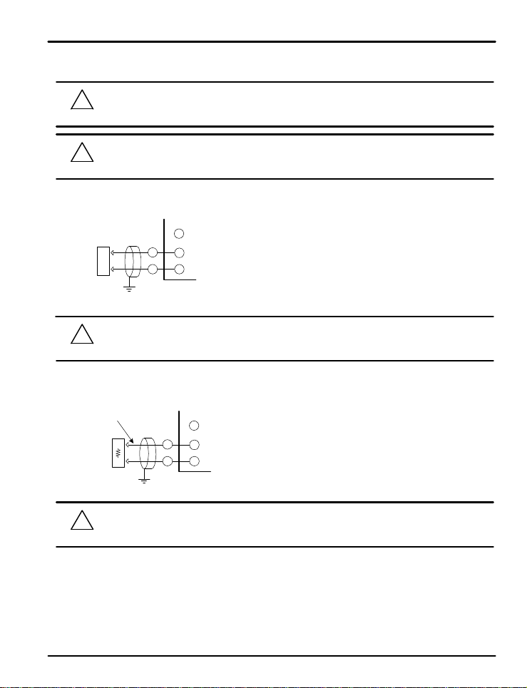
PD550 Series Nova Programmable Process and Temperature Controller Instruction Manual
7.8 Analog Output Connect i on
To prevent electric shock, b e su r e t o t u rn off p o we r to t h e Nov a C o n t r o l le r and the source circuit breaker
!
CAUTION
CAUTION
(1) Voltage Pulse Output (SSR) / Cu rren t Output ( S C R )
Control
Device
CAUTION
(2) Retransmitti n g Output (RE T)
4 to 20 mADC, 600 Ω max
or 14-18 VDC @ 20 mA max
Receiver
(Recorder, et c )
before wir i n g .
Be sure to connect to correct polaritie s . Conne ct i n g to a wron g pola rity may cause a co n t rolle r ma l f u n ct i o n .
!
Use shie ld e d wir e s for t h e wiring and connect independently to ground (1 point grounding).
SCR : 4 to 20 mADC, 600 Ω max imu m
SHIELD
+
OUT2,3 +
-
OUT2,3 -
NOVA
To prevent electric shock, b e su r e t o t u rn off p o we r to t h e Nov a C o n t r o l le r and t he s o u r c e ci r c u it b reake r
!
before wir i n g .
SHIELD
+
NOVA
SSR : 12 VDC min, 600 Ω minimum
RET+
RET-
!
CAUTION
To prevent electric shock, b e su r e t o t u rn off p o we r to t h e Nov a C o n t r o l le r and the source circuit breaker
before wir i n g .
55
Page 56
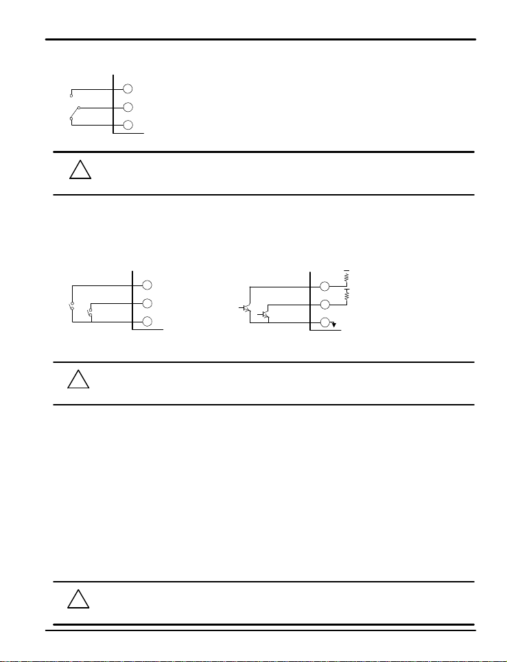
PD550 Series Nova Programmable Process and Temperature Controller Instruction Manual
7.9 Relay Output Connection (RELAY)
Relay: NO - Normal l y Open Conne c t io n
COM
Relay: NC - Normal ly Clos e d C onnection
NOVA
To prevent electric shock, b e su r e t o t u rn off p o we r to t h e Nov a C o n t r o l le r and the source circuit breaker
!
CAUTION
before wir i n g .
7.10 Digital Input Connection (DI)
Use a no-voltage contact switch such as relay.
The controller supplies the needed voltage (approx. 5 VDC) and current (approx . 1 mA) to trigger the input.
When usi ng an Open Collector (TR) as a trigger, use o ne wit h a 2 V or lower vo l t age rating wh e n "o n" and
100 μA or less leakage current when it is OFF.
+5V
DI_1
DI_2
DI_COM
NOVA
S Relay Contact Connection
To prevent electric shock, b e su r e t o t u rn off p o we r to t h e Nov a C o n t r o l le r and the source circuit breaker
!
CAUTION
before wir i n g .
DI_1
DI_2
DI_COM
NOVA
S Transistor Contact Connection
7.11 Use of an External Relay
Switching Inductive Loads
When using switching in ductiv e l o a d s, t h e u s e o f R C n e t wo r k s (snubbers) for AC loads or diodes for DC loads is
recommended to prevent disrupting the microprocessor's operation. The suppressors also prolong the life of the
relay contacts. Suppression can be obtained with resistor-capacitor (RC) networks or diodes assembled by the
user or purchased as complete assemblies.
For AC loads, choose R and C as follows:
R: 0.5 to 1 Ω for each volt across the contact
C: 0.5 to 1 μF for each amp through closed contacts
Notes:
1 . Use capacitors ra t ed f o r 250 VAC.
2. RC networks may affect load release time of solenoid loads. Check to confirm proper operation.
3 . RC networks are avai l a bl e f r o m P r e c is io n Digita l and should be applied to each relay contact switching an
inductive load. Part number: PDX6901
!
CAUTION
If the load inductance is over the controller specifications, the output may need a RC filter (snubber) or
diode to properly handle frequent relay switching operations.
56
Page 57
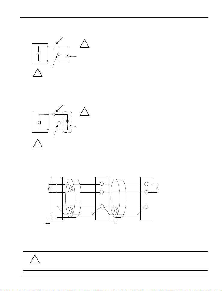
PD550 Series Nova Programmable Process and Temperature Controller Instruction Manual
(1) DC Auxiliary Relay
Controller
!
CAUTION
(2) AC Auxiliary Relay
Controller
!
CAUTION
External DC
power
External AC
Powe r
R
CAUTION
CAUTION
R
Relay
(Verify relay coil ratings are les s t h a n t h e voltage and current ratings of the relay
contacts of th e c o n t r o l le r)
Relay
(Verify relay coil ratings are les s t h a n t h e voltage and current ratings of the relay
contacts of th e c o n t r o l le r)
7.12 Communication Wiring (RS-485)
Master St a t i on NOVA Controller
RTX+
Terminating Resistor
RTX- RTX- RTX-
SG
!
Diode
(Connec t direct ly to the relay coil t e rminal s)
!
CR Filter (snubber)
(Connect directly to t h e relay c o i l t e r mi n a ls )
RTX+
SG
NOVA Controll e r
RTX+
Terminatin g Resisto r
SG
SHIELD
Up to 31 slave controllers ( N o va series controllers equipped with the RS-485 serial communication
option) can be connecte d .
Be sure to connect terminating resistors (220 Ω, 1/4 W) to slave and master controllers at
communication channel ends as shown above.
To prevent electric shock, b e su r e t o t u rn off p o we r to t h e Nov a C o n t r o l le r and the source circuit
!
CAUTION
breaker be f o re wiri n g .
57
Page 58
PD550 Series Nova Programmable Process and Temperature Controller Instruction Manual
Table of D-Registers:
The following data re g i st e r s a r e u s e d t o d irect t h e U S 1 an d U S 2 c o mmands or for Modbus communication.
PROCESS FUNCTION SET POINT SIGNAL ALARM PID IN/OUT
NO.
0 100 200 300 400 500 600
0
NPV 1.IST ALT1 ARW IN-T1
NSP 1.ISB ALT2 FUZZY INT-U2
TSP 1.ISH ALT3 C.MOD IN.RH3
1.ISL IN.RL4
1.ISD IN.DP5
MVOUT 2.IST AL-1 IN.SH6
2.ISB AL-2 IN.SL7
2.ISH AL-3 IN.FL8
PIDNO 2.ISL BSL9
NOWSTS 2.ISD RSL10
F.KEY, RST/P1/P2
HOLD,OFF/ON
STEP,OFF/ON
DO1 A1DB 1.P BSP111
DO2 A2DB 1.I BSP212
DO3 A3DB 1.D BSP313
ALSTS DO4 1.MR14
BS015
A1DY BS116
SIGNAL.STS A2DY BS217
A3DY BS318
ERROR RP1 BS419
20
AT AL1.H 2.P OUT121
AT-G AL2.H 2.I OUT222
AL3.H 2.D OUT323
2.MR24
PTNO SUB125
SEG.NO AL1.L SUB226
END.SEG.NO AL2.L27
RUN.TIME AL3.L28
SET.TIME RP229
30
LINK.CODE 3.P HEAT231
RPT 3.I32
RST PE-TM 3.D HEAT333
REN 3.MR34
US135
WAIT.TIME US236
LOCK O.ACT37
DI. SL CT38
DSP.H RHY39
DSP.L40
4.P OH41
4.I OL42
4.D43
58
Page 59
PD550 Series Nova Programmable Process and Temperature Controller Instruction Manual
PROCESS FUNCTION SET POINT SIGNAL ALARM PID IN/OUT
NO.
0 100 200 300 400 500 600
45
47
48
50
U RETL53
s54
e55
r56
57
A58
r59
e60
a61
62
63
64
65
66
67
68
69
70
71
72
73
74
75
76
77
78
79
80
81
82
83
84
85
86
87
4.MR44
PO46
RDV49
RET51
RETH52
COM.P
BAUD
PRTY
SBIT
DLEN
ADDR
RP.TM
59
Page 60
PD550 Series Nova Programmable Process and Temperature Controller Instruction Manual
PROCESS FUNCTION SET POINT SIGNAL ALARM PID IN/OUT
NO.
NOTE
NO.
0 100 200 300 400 500 600
88
89
90
91
92
93
94
95
96
97
98
99
?
RESERVED RESERVED RESERVED PT INFO PT1 PT2 RESERVED
700 800 900 1000 1100 1200 1300
0
Read Only Location
TMU 1.LC 2.LC1
STC 1.SSP 2.SSP2
WZ3
WTM 1.SP1 2.SP14
1.TM1 2.TM15
1.TS1 2.TS16
1.SP2 2.SP27
1.TM2 2.TM28
1.TS2 2.TS29
1.SP3 2.SP310
1.TM3 2.TM311
1.TS3 2.TS312
1.SP4 2.SP413
1.TM4 2.TM414
1.TS4 2.TS415
1.SP5 2.SP516
1.TM5 2.TM517
1.TS5 2.TS518
1.SP6 2.SP619
1.TM6 2.TM620
1.TS6 2.TS621
1.SP7 2.SP722
1.TM7 2.TM723
1.TS7 2.TS724
1.SP8 2.SP825
1.TM8 2.TM826
1.TS8 2.TS827
60
Page 61

PD550 Series Nova Programmable Process and Temperature Controller Instruction Manual
RESERVED RESERVED RESERVED PT INFO PT1 PT2 RESERVED
NO.
700 800 900 1000 1100 1200 1300
49
50
54
55
56
57
58
59
60
61
62
63
64
65
66
67
68
69
70
71
1.SP9 2.SP928
1.TM9 2.TM929
1.TS9 2.TS930
1.SPA 2.SPA31
1.TMA 2.TMA32
1.TSA 2.TSA33
1.SPB 2.SPB34
1.TMB 2.TMB35
1.TSB 2.TSB36
1.SPC 2.SPC37
1.TMC 2.TMC38
1.TSC 2.TSC39
1.SPD 2.SPD40
1.TMD 2.TMD41
1.TSD 2.TSD42
1.SPE 2.SPE43
1.TME 2.TME44
1.TSE 2.TSE45
1.SPF 2.SPF46
1.TMF 2.TMF47
1.TSF 2.TSF48
1.RPT 2.RPT51
1.RST 2.RST52
1.REN 2.REN53
61
Page 62

PD550 Series Nova Programmable Process and Temperature Controller Instruction Manual
RESERVED RESERVED RESERVED PT INFO PT1 PT2 RESERVED
NO.
700 800 900 1000 1100 1200 1300
72
73
74
75
76
77
78
79
80
81
82
83
84
85
86
87
88
89
90
91
92
93
94
95
96
97
98
99
62
Page 63

PD550 Series Nova Programmable Process and Temperature Controller Instruction Manual
Notes
?
Warranty and Retu rn Infor m a t i on
NOTE
Precision Digi t a l wa r rant s t h i s p r oduct to be free fr om material defects and workmanship under normal use and
service fo r t h ree y e a r s .
Please contact Precision Di g i t a l Technical S u p p o r t a t ( 800) 610-5239 or e-mail at [email protected] prior to
any product return. When Technical Support determines a product should be returned, a Return Material
Authorization (RMA) # wh ic h mu st b e i nc l u d ed o n t h e return shi p p in g label. Please also include the reason for
return, da t e o f p u r ch a s e , co n t a c t n ame , a n d h o w t o co n t a c t . Produc t s returned f or rea so n s o t h e r t han repair may
be subject to a resto c ki n g f e e . An y ret u r n s u n d e r a wa r ranty clai m sh o u ld b e returned f reigh t p r e p a i d . U p o n
warranty confirmation Precision Digital will repa ir o r re pla ce and retur n the unit at no charge v ia UPS Ground.
Other shipping is ava il a b le u pon r equest and at customer expense. All product returns should be shipped to:
Return Authorization # ___________
Precision Digital, 89 October Hill Road Ste 5, Ho lliston , MA 01746 USA
Attention: Technical Support
Precision Digital Technical Support is trained and eager to serve you. We have found most start-up problems to
be the result of incorrect signal co n n e ct i o n s a n d / o r p rogr a mmin g . M o st o f t e n P r e c is io n D i g it a l Technical
Support ca n q u ic kl y c o r rect t h e se i ss u e s o ver the t e le phone.
63
Page 64

PD550 Series Nova Programmable Process and Temperature Controller Instruction Manual
How to Contact Precision Digital
z
For Technical Support
Call: (800) 610-5239 or (508) 655-7300
Fax: (508) 655-8990
Email: [email protected]
z
For Sales Support o r t o p l ace an o rd e r p le a s e
Call: (800) 343-1001 or (508) 655-7300
Fax: (508) 655-8990
Email: [email protected]
z
For the latest version of this manual, please visit
www.predig.com
LIM550_C
06/0 9
 Loading...