


SABRE P MODEL PD603
PROCESS METER
Instruction Manual
0-20, 4-20 mA, 0-5, 1-5, 0-10, 10 V Inputs
Type 4X, NEMA 4X, IP65 Front
Shallow Depth Case 3.6" Behind Panel
4 Digit Display, 0.56" (14 mm) High, Red LEDs
Easy Front Panel Programming
Scale without a Signal Source
Calibrate with a Signal Source
Maximum/Minimum Display
Universal Power Supply 85-265 VAC
12-36 VDC/12-24 VAC Power Option
24 VDC @ 200 mA Transmitter Supply Option
PRECISION DIGITAL CORPORATION
89 October Hill Road • Holliston MA 01746 USA
Tel (800) 343-1001 • Fax (508) 655-8990
www.predig.com

Sabre P Model PD603 Process Meter Instruction Manual
Disclaimer
The information contained in this document is subject to change
without notice. Precision Digital makes no representations or warranties with respect to the contents hereof, and specifically disclaims
any implied warranties of merchantability or fitness for a particular
purpose.
© 2010 Precision Digital Corporation. All rights reserved.
2

Sabre P Model PD603 Process Meter Instruction Manual
INTRODUCTION
The Sabre P model PD603 is an easy to use process input meter. It
accepts 0-20 mA, 4-20 mA, 0-5, 1-5, or ±10 V input signals. The four
front panel buttons make the setup and programming an easy task.
The isolated 24 VDC transmitter power (optional) can be used to po wer
the input transmitter or other devices.
ORDERING INFORMATION
85-265 VAC*
Model
PD603-6R0-0 PD603-7R0-0 Process Meter
12-36 VDC*
Model
Description
PD603-6R0-1
*All models may be powered from AC or DC, see Specifications for details.
Process Meter with
24 V transmitter supply
NEMA 4 & NEMA 4X Enclosures
Model # of
Description Mounting
Meters
PDA2501 1 Plastic NEMA 4X Enclosure Through Door
PDA2502 2 Plastic NEMA 4X Enclosure Through Door
PDA2503 3 Plastic NEMA 4X Enclosure Through Door
PDA2504 4 Plastic NEMA 4X Enclosure Through Door
PDA2505 5 Plastic NEMA 4X Enclosure Through Door
PDA2506 6 Plastic NEMA 4X Enclosure Through Door
PDA2601 1 Stainless Steel NEMA 4X Enclosure Through Door
PDA2602 2 Stainless Steel NEMA 4X Enclosure Through Door
PDA2603 3 Stainless Steel NEMA 4X Enclosure Through Door
PDA2604 4 Stainless Steel NEMA 4X Enclosure Through Door
PDA2605 5 Stainless Steel NEMA 4X Enclosure Through Door
PDA2606 6 Stainless Steel NEMA 4X Enclosure Through Door
PDA2701 1 Steel NEMA 4 Enclosure Through Door
PDA2702 2 Steel NEMA 4 Enclosure Through Door
PDA2703 3 Steel NEMA 4 Enclosure Through Door
PDA2704 4 Steel NEMA 4 Enclosure Through Door
PDA2705 5 Steel NEMA 4 Enclosure Through Door
PDA2706 6 Steel NEMA 4 Enclosure Through Door
PDA2801 1 Plastic NEMA 4X Enclosure Through Cover
3

Sabre P Model PD603 Process Meter Instruction Manual
Table of Contents
INTRODUCTION ------------------------------------------------------------ 3
ORDERING INFORMATION --------------------------------------------- 3
SPECIFICATIONS ---------------------------------------------------------- 6
General ------------------------------------------------------------------------------- 6
Process Input ---------------------------------------------------------------------- 7
COMPLIANCE INFORMATION ----------------------------------------- 8
Safety --------------------------------------------------------------------------------- 8
Electromagnetic Compatibility ----------------------------------------------- 8
SAFETY INFORMATION ------------------------------------------------- 9
INSTALLATION ------------------------------------------------------------ 10
Unpacking ------------------------------------------------------------------------- 10
Panel Mounting ------------------------------------------------------------------ 10
Connections ---------------------------------------------------------------------- 11
Connector Labeling ---------------------------------------------------------- 11
Power Connections ---------------------------------------------------------- 11
Signal Connections ---------------------------------------------------------- 12
SETUP AND PROGRAMMING ---------------------------------------- 14
Front Panel Buttons and Status LED Indicators --------------------- 15
Display Functions and Messages ----------------------------------------- 16
Main Menu ------------------------------------------------------------------------ 17
Setting Numeric Values ------------------------------------------------------ 18
Setting Up the Meter (setu) ------------------------------------------------- 19
Setting the Input Signal (inpt) -------------------------------------------- 19
Setting the Decimal Point (dec.p) ----------------------------------------- 20
Programming the Meter (prog) --------------------------------------------- 21
Scaling the Meter (ScAL) ---------------------------------------------------- 22
Calibrating the Meter (Cal) ------------------------------------------------- 24
Setting Up the Password (pass) ------------------------------------------- 25
Locking the Meter ------------------------------------------------------------ 25
Unlocking the Meter ---------------------------------------------------------- 25
OPERATION ---------------------------------------------------------------- 27
Front Panel Buttons Operation -------------------------------------------- 27
Maximum/Minimum Readings ---------------------------------------------- 28
MOUNTING DIMENSIONS ---------------------------------------------- 29
4

Sabre P Model PD603 Process Meter Instruction Manual
TROUBLESHOOTING ---------------------------------------------------- 30
Troubleshooting Tips --------------------------------------------------------- 30
QUICK USER INTERFACE REFERENCE GUIDE ---------------- 31
Table of Figures
Figure 1. Panel Cutout and Mounting ............................................... 10
Figure 2. Connector Labeling - Meter with 24 V Supply .................. 11
Figure 3. Power Connections ............................................................ 11
Figure 4. Transmitter Powered by Ext. Supply or Self-Powered .... 12
Figure 5. Transmitters Powered by Internal Supply (Optional) ...... 12
Figure 6. Voltage Input Connections ................................................ 13
Figure 7. Meter Dimensions - Side View ........................................... 29
Figure 8. Case Dimensions - Top View ............................................. 29
5

Sabre P Model PD603 Process Meter Instruction Manual
SPECIFICATIONS
Except where noted all specifications apply to operation at +25°C.
General
DISPLAY 0.56" (14 mm) high, red LED
DISPLAY
UPDATE RATE
OVERRANGE
UNDERRANGE
PROGRAMMING
METHODS
RECALIBRATION All ranges are calibrated at the factory.
MAX/MIN
DISPLAY
PASSWORD Programmable password restricts modification of
NON-VOLATILE
MEMORY
POWER
OPTIONS
FUSE Required fuse: UL Recognized, 5 A max, slow blow
ISOLATED
TRANSMITTER
POWER SUPPLY
NORMAL MODE
REJECTION
ISOLATION 4 kV input-to-power line
OVERVOLTAGE
CATEGORY
ENVIRONMENTAL Operating temperature range: 0 to 65°C
CONNECTIONS Removable screw terminal blocks accept 12 to 22 AWG
Four digits (-1999 to 9999), automatic lead zero blanking.
5/second
Display flashes
Display flashes
Four front panel buttons
Recalibration is recommended at least every 12 months.
Max/min readings reached by the process are stored until
reset by the user or until power to the meter is turned off.
programmed settings.
All programmed settings are stored in non-volatile memory
for a minimum of ten years if power is lost.
85-265 VAC, 50/60 Hz; 90-265 VDC, 20 W max
or 12-36 VDC, 12-24 VAC, 6 W max
Up to 6 meters may share one 5 A fuse
P+, P- terminals: 24 VDC 10% @ 200 mA max
64 dB at 50/60 Hz
500 V input-to-24 V supply
Installation Overvoltage Category II:
Local level with smaller transient overvoltages than Installation Overvoltage Category III.
Storage temperature range: -40 to 85°C
Relative humidity: 0 to 90% non-condensing
wire, RJ11 for factory use only.
9999
-1999
6

Sabre P Model PD603 Process Meter Instruction Manual
ENCLOSURE 1/8 DIN, high impact plastic, UL 94V-0, color: gray
MOUNTING 1/8 DIN panel cutout required. Two panel mounting brack-
TIGHTENING
TORQUE
OVERALL
DIMENSIONS
WEIGHT 8.5 oz (241 g)
WARRANTY 1 year parts & labor
EXTENDED
WARRANTY
et assemblies provided
Screw terminal connectors: 4.5 lb-in (0.5 Nm)
2.45" x 4.68" x 4.19" (62 mm x 119 mm x 106 mm)
(H x W x D)
1 or 2 years, refer to the Price List for details.
Process Input
INPUTS Field selectable:
ACCURACY ±0.05% FS ±1 count
FUNCTION Linear
TEMPERATURE
DRIFT
DECIMAL POINT Up to three decimal places:
CALIBRATION
RANGE
INPUT
IMPEDANCE
INPUT
OVERLOAD
0-20, 4-20 mA, 0-5, 1-5, 0-10 V, or 10 V
50 PPM/C from 0 to 65C ambient
d.ddd, dd.dd, ddd.d, or dddd
An Error message will appear if input 1 and input 2 signals
are too close together.
Input
Range
4-20 mA 0.40 mA
10 V
Voltage ranges: greater than 1 M
Current ranges: 50 - 100
Current input protected by resettable fuse.
Fuse resets automatically after fault is removed.
Minimum Span
Input 1 & Input 2
0.20 V
(depending on resettable fuse impedance)
7

Sabre P Model PD603 Process Meter Instruction Manual
COMPLIANCE INFORMATION
Safety
UL LISTED USA and Canada
UL FILE NUMBER E160849
FRONT PANEL UL Type 4X, NEMA 4X, IP65; panel gasket provided
LOW VOLTAGE
DIRECTIVE
Electromagnetic Compatibility
EMISSIONS
Radiated
Emissions
AC Mains
Conducted
Emissions
IMMUNITY
RFI - Amplitude
Modulated
Electrical Fast
Transients
Electrostatic
Discharge
RFI - Conducted
AC Surge
Surge
Power-Frequency
Magnetic Field
Voltage Dips
Voltage
Interruptions
UL 508 Industrial Control Equipment
EN 61010-1:2001
Safety requirements for measurement, control, and
laboratory use
EN 55011:2007
Group 1 Class A ISM emissions requirements
Class A
Class A
EN 61326-1:2006
Measurement, control, and laboratory equipment
EN 61000-6-2:2005
EMC heavy industrial generic immunity standard
80 -1000 MHz 10 V/m 80% AM (1 kHz)
1.4 - 2.0 GHz 3 V/m 80% AM (1 kHz)
2.0 - 2.7 GHz 1 V/m 80% AM (1 kHz)
±2kV AC mains, ±1kV other
±4kV contact, ±8kV air
10V, 0.15-80 MHz, 1kHz 80% AM
±2kV Common, ±1kV Differential
1KV (CM)
3 A/m 70%V for 0.5 period
40%V for 5 & 50 periods
70%V for 25 periods
<5%V for 250 periods
8

Sabre P Model PD603 Process Meter Instruction Manual
Note:
Testing was conducted on PD603 meters installed through the covers of grounded metal enclosures with cable shields grounded at the
point of entry representing installations designed to optimize EMC
performance.
Declaration of Conformity available at www.predig.com
SAFETY INFORMATION
!
CAUTION: Read complete
instructions prior to installation and operation of the
meter.
WARNING
Hazardous voltages exist within enclosure. Installation and service
should be performed only by trained service personnel.
9
WARNING: Risk of
electric shock.
Sabre P Model PD603 Process Meter Instruction Manual
INSTALLATION
There is no need to remove the meter from its case to complete the installation, wiring, and setup of the meter.
Unpacking
Remove the meter from box. Inspect the packaging and contents for damage. Report damages, if any, to the carrier.
If any part is missing or the meter malfunctions, please contact
your supplier or the factory for assistance.
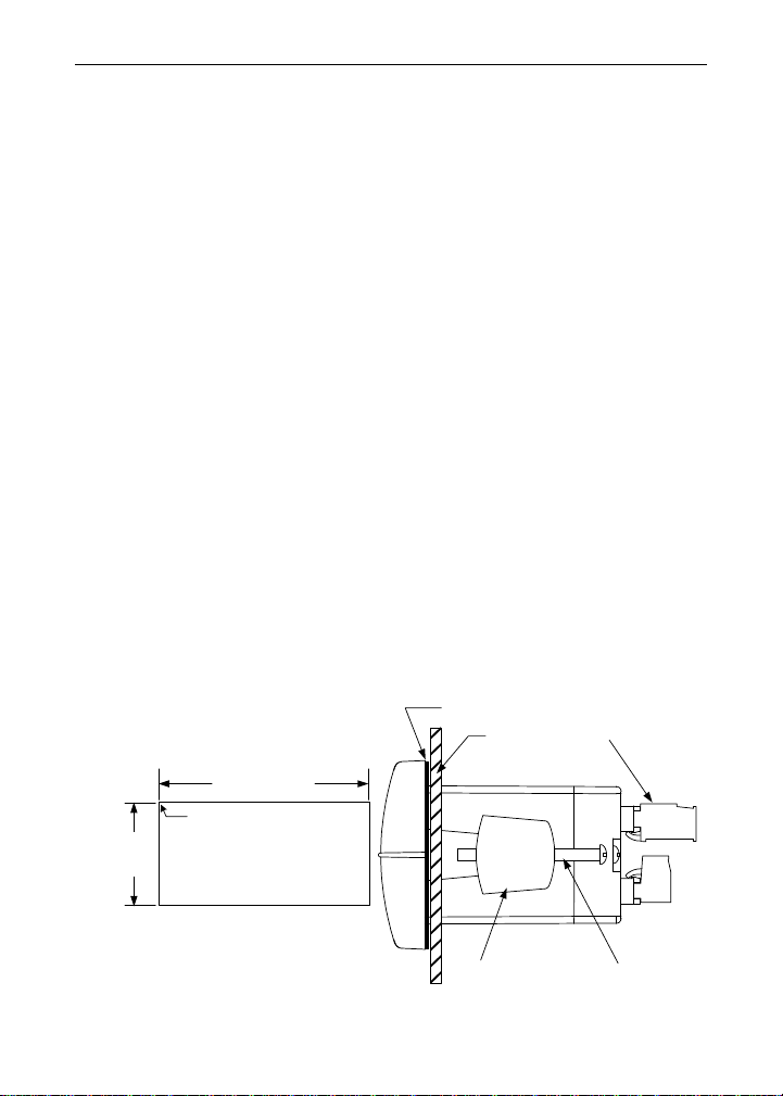
Panel Mounting
Prepare a standard 1/8 DIN panel cutout – 3.622" x 1.772" (92 mm
x 45 mm). Refer to Mounting Dimensions, page 29 for more details.
Clearance: allow at least 4" (102 mm) behind the panel for wiring.
Panel thickness: 0.04" - 0.25" (1.0 mm - 6.4 mm).
Recommended minimum panel thickness to maintain Type 4X
rating: 0.06" (1.5 mm) steel panel, 0.16" (4.1 mm) plastic panel.
Remove the two mounting brackets provided with the meter (back-off
the two screws so that there is ¼" (6.4 mm) or less through the
bracket. Slide the bracket toward the front of the case and remove).
Insert meter into the panel cutout.
Install mounting brackets and tighten the screws against the panel.
To achieve a proper seal, tighten the mounting bracket screws
evenly until meter is snug to the panel along its short side. DO NOT
OVER TIGHTEN, as the rear of the panel may be damaged.
1.772"
B
(45mm)
A
3.622" (92mm)
Square Corners to 0.060"
(1.5mm) Max Radius
Panel Cutout
to DIN 43700
Gasket
Panel
Removable
Connectors
Tolerances:
A: +0.032 (+0.8mm)
-0.000 (-0.0mm)
B: +0.024 (+0.6mm)
-0.000 (-0.0mm)
Figure 1. Panel Cutout and Mounting
10
Mounting
Bracket
Mounting
Screw
 Loading...