

LIMIT CONTROLLER
®
NOVA PD570 Series
Instruction Manual
PD570 & PD578
PRECISION DIGITAL CORPORATION
89 October Hill Road z Holliston MA 01746 USA
Tel (800) 343-1001
z
Fax (508) 655-8990
PD570 Series Nova Process and Temperature Limit Controller Instruction Manual
Disclaimer
The information contai ned i n t h i s docu m ent i s su b j ec t t o c h ang e wi t hou t n oti ce.
Precision D i g i t al C or p or ati on m akes no repr esentati ons or warranties with
res p ect t o t he c on t en ts h ereof , an d s p ecifically disclai m s any i m p l ied warran tie s
of merchantability or fitness f or a particular purpose.
Registered Trademarks
MODBUS® is a registered tr ademar k of Sch n eid er A u t omati on I n c. A l l ot h er
trademarks men t ion ed i n t hi s doc u men t ar e t h e pr op ert y of their respective
owner s.
Visit our Web S i te
http://www.predig.com
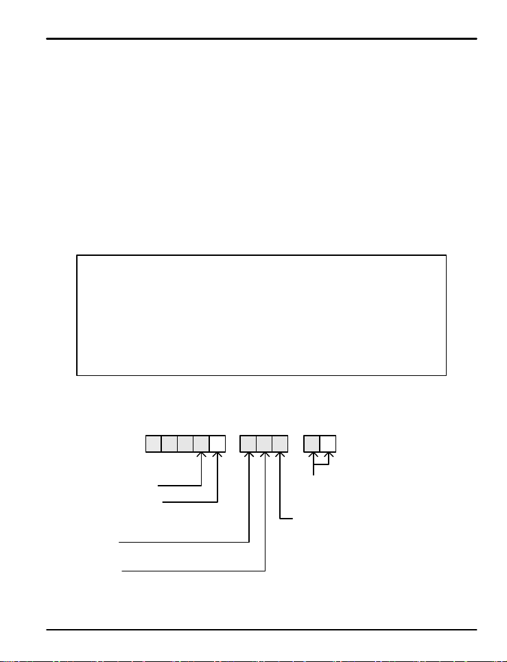
Nova PD570 Series Model Number Guide
0-6RA-10PD5 7
Limit Controll er
Size - DIN Cutou t
0 = 1/16 DI N
8 = 1/4 D I N
Power
6 = 100-240 VAC
Display
R = Red LED
Options
Main Control Ou tp u t
output
©2009 Precision Digital C or p orat i on. A l l r i g h t s reserved.
2
10 = 1 alarm relay
14 = 1 alarm relay & RS-485
A = 1 latching relay & 1 analog

PD570 Series Nova Process and Temperature Limit Controller Instruction Manual
Table of Contents
1. Safety Guide and Specifications 5
1.1 Specifications
7
2. Front Panel Buttons and LED Indicators 11
3. Parameter Map
12
4. Operation Flow Chart 13
5. Controller Parame t er Se t up
5.1 Input Group ( G.IN )
5.2 Control Group (G.CTL)
5.3 Alarm Group (G.ALM)
5.4 Retransmission Group (G.RET)
5.5 Communication Group (G.COM)
6. Error Display and Correction
7. Installation
7.1 Dimensions and Panel Cutout s
14
14
18
23
26
27
29
30
30
7.2 Panel Mounting
7.3 Power Cable Specification
7.4 Terminal Specification
7.5 Terminal Assignment, Connections, and Ratings
3
32
33
33
34

PD570 Series Nova Process and Temperature Limit Controller Instruction Manual
7.6 Grounding and Power Cable Connection
7.7 Signal Input Connection
7.8 Retransmission Output Connection (RET)
7.9 Relay Output Connection (RELAY)
7.10 Use of an External Relay
7.11 Communication Wiring (RS485)
Appendix
Table of D-Regist er s
Tables and Figures
Table 1: Universal Input Selection
Table 2: Alarm Selection
Fig 1: Temperature Bias
Fig 2: Bias Formula Calculation
Fig 3: Operation of Limit Functions with O.ACT set to REV
36
36
37
37
38
39
40
14
24
16
16
19
Fig 4: Operation of Limit Functions with O.ACT set to FWD
Fig 5: Example of Limit Control Relay Operat ion an d Reset Fu n ct i on
Fig 6: Alarm Operation
4
19
20
24
PD570 Series Nova Process and Temperature Limit Controller Instruction Manual
1. Safety Guide and Speci f ica t ion s
The following safety symbols are used in this manual
(1) This symbol notifies the use r o f s pe c i f ic in f o rmatio n r e l a t in g t o t h e sa f e o p e ratio n o f t h e co n t roller.
!
CAUTION
?
NOTE
&
!
CAUTION
!
CAUTION
Information noted with this symbol must be observed to protect the user from injury and to prevent damag e
to the product.
(A) For User: Be awa re of t h i s ma rking i n t h e ma n u al a n d r e f e r to th e e xplanat io n i n t h e manua l to
(2) For Installer : Stud y the warning s marked t o p r e vent inju ry and dama g e .
(2) Functional ea rth te rminal : This symbol i n d ic a t e s t h a t t h e t e r mi n a l mu st b e c onnected to ground.
(3) This symb o l in d i ca t e s a d d it i o n a l i n f o r ma t io n o n t h e f e a t u r e s o f t h e p r oduct.
(4) This symbol directs the r e a d e r to further info r ma t i o n o n t h e cu r rent t o pi c .
Precautions R eg a rd i ng T his Instr ucti o n Ma n ua l
(1) This manual must be kept in the possession of the end user and in a suitable place for the operator to
study and to check the functions of the product.
(2)The installer and oper ator should carefully study and understand how to operate this product before use.
(3)This manual describes the functions of the product. Precision Digital Corporatio n d o e s n o t guar antee
that the functions will suit a particu lar pu r pose .
(4) The contents of this manual have been reviewed for accuracy and correctness. However, shou l d a n y
errors or omission s c o me t o t h e at t e n t i o n o f t h e u se r, con t a ct t e c h n ic a l s upport as listed on the back of this
manual
Safety Procedures and Unauthorized Modification Warning
(1)In order to prote c t t h is p r oduct and the system controlled by it against damage and ensure its safe use,
make certain t h a t a ll o f t h e sa f e t y instructi o n s a n d p r e c a u t io n s in t h i s manual are strictly adhered to.
(2)Precision Digital Corpo ratio n d o e s not gua r a n t e e s a f e t y i f t h e p r o d u ct s a r e n o t h andled in accordance
with this instruction manual.
(3) If separate prot ec t i o n o r safe t y circ u it s a r e t o b e in s t a ll e d in t h e s y s t e m wh ic h is co n t rolle d b y t h i s p r oduct,
ensure that such circu i t s a re ins t a ll e d e xternal t o t h is p r oduct.
(4) Do not make modifications or additions internally to the product. It may cause personal in ju r y to t h e u se r or
damage to the product.
(5)Contact tech n ic a l s u p p ort as l is t e d o n t h e b a ck o f t he manual for warranty and repair issues.
(6)Exposure to e xcessive mo i st u re, el e ct rical o verloads, or mechanical vibration may damage the product.
prevent injury and damage.
!
CAUTION
Limited Liability
Precision Digital Corpo ration a s su me s n o li a b ility t o an y pa rt y fo r any lo ss or d amage, dir ect or in dir ect ,
caused by the use of or any unpredictable defect of the product.
5

PD570 Series Nova Process and Temperature Limit Controller Instruction Manual
Operational Enviro nment Precautions
!
CAUTION
CAUTION
(1)Only operate the c o nt rolle r wh e n i t is p r o p e r l y i n s ta l l e d .
(2)When installing the controller, select a location where:
Rear terminal s a re pr o t e ct e d f r o m a c ci dental contact.
Mechanic a l vibrati o n s a re minima l .
No corrosive ga s i s p resen t .
Temperature fluctuation is minimal.
Temperature can be maintained between 10 and 50 ºC (50 and 110 ºF) wi t h 20 t o 9 0 % RH.
No direct heat r adiation is present.
High levels of electromagnetic interference are not present
The unit is not exposed to water.
No flammable materials are present.
Dust particles ar e n o t p r e s e n t in t h e a i r .
Expo s u r e t o u l t r a violet r a y s is min i mal .
Openings on t h e r e a r of th e c o n t r o l le r are n o t b lo c ke d .
(3)This unit is suitable f o r in s t a l la t i o n in a n e n viornmen t cl a ss if i e d a s Pollution D e g ree 2.
(4)This unit is designated as Installation Category I I .
(5) If the equipment is used in a manner not specified by the manufacturer, the protection provided by
the equipment may be impair e d .
(6)A switch or circuit-brea ke r acti n g a s t h e d is c onnect dev ice shall be included in the application or the
installation.
Controller Mounting Precautions
!
Keep the input circuit wiring as far a s poss i b le away from p o wer and grou n d circuits.
Keep the u n i t s i n 1 0 t o 5 0 º C ( 5 0 t o 1 1 0 º F) with 20% to 90% relat i ve humidit y (RH) .
The controlle r may n e e d a wa r m u p p e r i o d t o retu r n t o o p e r a t i n g t e mpe rature ra nges when below 10ºC.
To prevent electric sho c k, b e s u r e t o t u r n o f f t h e p o we r sour c e a n d ci r c u it b reake r b e f o r e wi r i n g .
The po we r requi r e me n t s are 100 t o 240 VAC, 50/60 Hz , 10 VA max. Do not switch power
supplies without first disconnecting the power supply.
F ollow the operating procedures and precautions in the manual to avoid fire, shock, damage to the unit,
or injury. Follow the operations and mounting directions indicated in this manual.
Always create a ground connection where indicated, however do not ground to gas pipes,
water pipes, lighten i n g r o d s, o r oth er pot e n t ia l ly haz a r d o u s me t a l o b j e ct s .
Do not apply power to the unit until all connections have been ma d e .
Do not cov e r t h e venting h o le s in t h e r e a r of t h e u n i t .
6

PD570 Series Nova Process and Temperature Limit Controller Instruction Manual
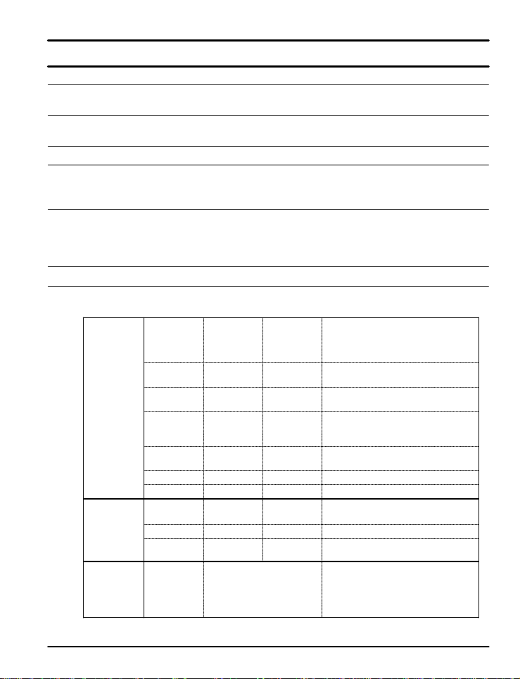
1.1 SPECIFICATIONS
Except where note d a ll sp e c i f ic a t io n s apply to operation at 23ºC.
General
DISPLAY Dual 4 digits, red LED, -1999 to 9999
DIN Sizes PV Display SP Display Weight
mm (inch) mm (inch) g (oz)
1/16 11.3 (0.45) 9.5 (0.37) 198 (7.0)
1/4 20.5 (0.81) 11.0 (0.43) 389 (13.7)
FRON T PANEL 1/16 DIN: IP65; 1 / 4 D I N : IP 5 5
SAMPLING TI ME 250 ms
OVERRANGE Ove r r ange PV read s ov R, under range PV reads -ovR
PROGRAMMING Four front p anel b u t t ons and Modbus
METHODS
NOISE FILTER Programmable from 1 t o 1 2 0
CALIBRATION All rang es are calibr at ed at t h e fa ctory
MAX/MIN Max/mi n readi n g s r eached b y the p r oces s ar e stored u n t il
DISPLAY limit reset or un t il p ower t o th e c on t r oll er i s t u r n ed of f.
OVER LIMIT Time since the last PV over l i mi t oc cur nace is s t or ed u n t i l t he
TIMER system is reset by the user or until power to the controller is
turned off.
PASSW ORD Progr a mma bl e password restr icts mod ifi cati o n of
programmed settin g s
POWER 100-240 VAC, 50/ 6 0 HZ, 1 0 Watts
FUSE Required fuse: UL Recognized, 1 A, 250 V, slow blow
ISOLATION 2300 V input-to-output-to-power lin e;
4 kV relay output-to-input/output/power line
ENVIRONMENTAL Operating temperatu re range: 10 º C to 50ºC ( 5 0ºF to 110ºF)
Relative humid i t y: 2 0 t o 90 % n on - condensing
MOUNTING 1/16 or 1/4 DIN size cutout required
Two panel mounti ng b r acket as sembli es p r ovid ed for P D 5 7 8
One one-pi ec e bracket provided f or t h e P D 5 7 0
WARRA NTY Thr ee years p ar t s an d la bor
7
PD570 Series Nova Process and Temperature Limit Controller Instruction Manual
Process and Temperatu re I nputs
TEMPERATURE DRIFT Refer to accuracy specifications below
DECIMAL POINT Up to three decimal places for process inputs:
9.999, 99.99, 999.9, or 9999
REAR JUNCTION Automatic or off s ett i n gs f or t emp er atu r e i nputs . N o user
COMPENSATION calibrati on r equ i r ed .
OFF S ET ADJUS T MENT Four programmable input bias zones
SENSOR BREAK Open sensor i n di cated by P V d i s p l ay f l as h i n g S.OPN.
DETECTION Up or down scale, user selectable; relays will follow the up
or down scale selection.
TRANSMITTER 14 to 18 VDC @ 20 mA; availab l e at term i nals OUT 2 or
SUPPLY OUT3, instead of a retr ansmit t i n g an alog ou t p ut
UNIVERSAL IN PU T TYPE A ND A CCURACY
Temp Temp
Range (ºC) Range (ºF) Accuracy*
K1 -200 to 1370 -300 to 2500
K2 -19 9 . 9 t o 9 9 9.9 0 t o 2300 > 0°C : ±0.1 % F S ± 1 d ig i t
J -199.9 to 999.9 -300 to 2300 < 0°C : ±0.2% F S ± 1 d ig i t
T -199.9 to 400. 0 -300 to 750
B 0 to 1800 32 to 3300 > 400°C : ±0.15 % F S ± 1 d ig i t
Thermocouple S 0 to 1700 32 to 3100
Input Type
RTD PtC - 19.99 to 99. 9 9 -4.0 to 212.0 ±0.2% FS ± 1 d i g it
Process 0 to 10 V
*Performance with i n recomme n d e d operating conditions (10 to 50°C, 20 to 90% RH)
**For a range scale of 0 to 100°C: +0.3°C +1 digit, and for a range scale of -100 to 100°C: +0.5°C +1 digit
R 0 to 1700 32 to 3100 ±0.15% F S ± 1 d i g it
E -199.9 to 999 . 9 -300 to 1800 > 0°C : ±0.1 % FS ±1 d i g it
L -199.9 to 900.0 -300 to 1600 < 0°C : ±0.2% FS ±1 d i g it
U -199.9 to 400.0 -300 to 750
N -200 to 1300 -300 to 2400 > 0°C : ±0.1% FS ±1 d ig i t
W 0 to 2300 32 to 4200 ±0.2% FS ±1 d ig i t
Platinel II 0 to 1390 32 to 2500 ±0.1% FS ±1 d i g it
PtA -199.9 to 850.0 -300 to 1560 ±0.1% FS ±1 d ig i t **
PtB -199.9 to 500.0 -199.9 to 999.9
JPtA -199.9 to 500.0 -199.9 to 999. 9 ±0.1% FS ± 1 d i gi t * *
JPtB -150.0 to 150.0 -199.9 to 300. 0
0.4 t o 2 .0 V ±0.1% FS ± 1 d i g it
1 to 5 V
-10 to 20 mV
0 to 100 mV
0.400 to 2. 0 0 0
1.000 to 5. 0 0 0
0.00 to 10.00
-10.00 to 20.00
0.0 to 100 . 0
< 400°C : ±5% FS ± 1 d ig i t
< 0°C : ±0.2 5 % F S ± 1 d ig i t
Display range can be scaled between -1999 and 9999.
4 to 20 mA Inp ut
To accept a 4 to 20 mA signal, select 0.4 to 2.0 VDC input
and connect a 100 Ω resistor across the input terminals.
8

PD570 Series Nova Process and Temperature Limit Controller Instruction Manual
Relay Outputs
RATINGS Out1: 250 VAC @ 3 A or 30 V DC @ 3 A ( resisti ve load)
Alarm: 250 VA C @ 1 A or 3 0 V D C @ 1 A ( r esis t i ve load)
ELECTRICAL NOISE A suppr ess or (snubber) s hould be connected to each
SUPPRESSION r elay co ntact switching induct ive loads, to prevent
disru p tion t o the micropr oces sor ' s operati on .
Recommended suppressor value: 0.1 μF/470 Ω,
250 VAC (PDX6901)
DEADBAND For alarm operations , 0 - 100% of full scale, user selectable
HIGH OR LOW User may progr am t h e alarm r elay for hi gh or l ow trip p oin t
ALARM
DEVIATION ALARM User may pr ogram the alar m r elay f or a hi g h , l ow, or r an ge
set point d eivati on al arm .
RELAY OPERATION Out 1, the Limit Control Relay, will activate when the PV
exceeds the limit set point. It will remain in this state until the
PV no longer exceeds the limit set point and the relay is reset
by the user. T h e alarm relay m ay b e set to any al ar m typ e.
TIME DELAY 0 to 99 minutes 59 s econds alarm trip delay for each alarm.
FAIL-SAFE Programmable
OPERATION Independent for each alarm relay
AUTO INITIALIZATION When power is applied to the controller, alarm relays will
reflect the state of the input to the controller except standby
alarms.
9

PD570 Series Nova Process and Temperature Limit Controller Instruction Manual
Retransmitting Output
OUTPUT RANGE Retransmitting: 4 to 20 m A ( 600 Ω maximum)
SCALING RANGE Any display range (see range for the input selected)
ACCURACY +0.1% of full scal e
Serial Communications
PROTOCOLS Modbus (ASCII, RTU), PC software,
UNIT ADDRESS 1 to 99 (Max 31 units connected)
BAUD RATE 600, 1200, 2400, 4800, 9600, 19200 bps, user selectable
RESPONSE TIME 0 to 100 ms delay response time
10 ms inc remen t s user selectab l e
DATA 7 or 8 bit user selectable
PARITY None, even, or od d
Approvals
UL R E C OGN IZED USA and Canada
Process Control Equipment
UL F I L E N UMBER E244207
CE COMP L I A N T
10
PD570 Series Nova Process and Temperature Limit Controller Instruction Manual
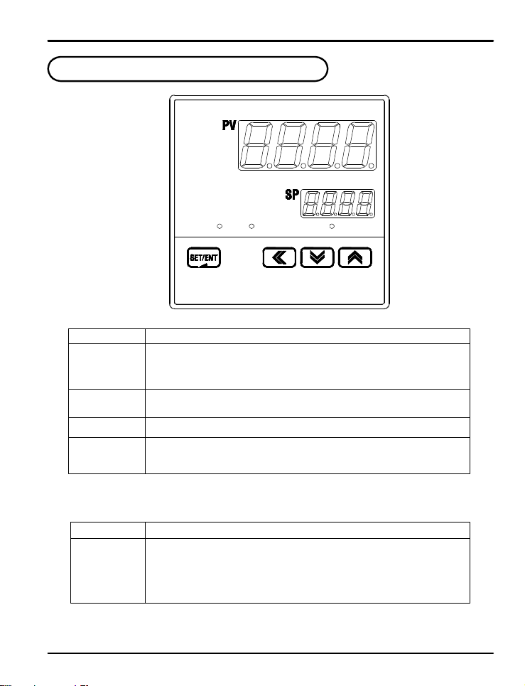
2. Front Panel Buttons and LED Indicato rs
Control K ey s
KEY Function
SET/ENT
(ENTER)
S / T
(UP/DOWN)
W (SHIFT)
W RST
Pressing SET/ EN T key for at le a s t 3 s e c onds switches between the operating display and
the parameter s e t t i ng d i sp l a y. T h is ke y is use d t o verify and by pass parameter settings
when in the parameter group display.
Used to change the value of digits when setting parameters.
Used to move between parameter groups.
Used to move to the next digit when setting parameters.
Holding for 3 seconds will re set the l imi t co n t rol la t ch i n g r e l ay if it i s n o t i n a n over limit
condition. This will reset the time, maximum, and minimum display value s .
ALMOVER OUT
LED Display
LED Function
OVER
OUT
ALM
LED activated when the P V value is h igher than the limit setting if HI.LO is set to HI.
LED activate d wh e n t h e P V value is lo we r than t h e l imit s e t t in g i f H I.LO i s s e t t o L OW.
LED on while the latching relay is de-energized (when in over limit conditions for
reverse/failsafe mode).
LED on when the alarm relay energizes.
11
PD570 Series Nova Process and Temperature Limit Controller Instruction Manual
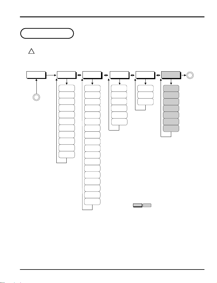
3. Para meter M ap
PwD: Lockout Pass word
?
Use the ST arrows to enter the
NOTE
password and press the SET/ENT
key. The default password is 0.
PWD
SET/
ENT
A
ST ST ST ST T
G.CTL
SET/ENT SET/ENT SET/ENT SET/ENT SET/ENT
SP
HI.LO
R.MD
O.ACT
R.HYS
SPRH
SPRL
LOCK
U.PWD
TMU
INIT
G.IN
IN-T
IN-U
IN.RH
IN.RL
IN.DP
IN.SH
IN.SL
IN.FL
BSL
RSL
BSP1
BSP2
BSP3
BS0
BS1
BS2
BS3
BS4
G.ALM
ALT1
AL-1
AL1.H
AL1.L
A1DB
A1DY
G.RET
RET
RETH
RETL
G.COM
COM.P
BAUD
PRTY
SBIT
DLEN
ADDR
RP.TM
: Optional feature
A
12
PD570 Series Nova Process and Temperature Limit Controller Instruction Manual
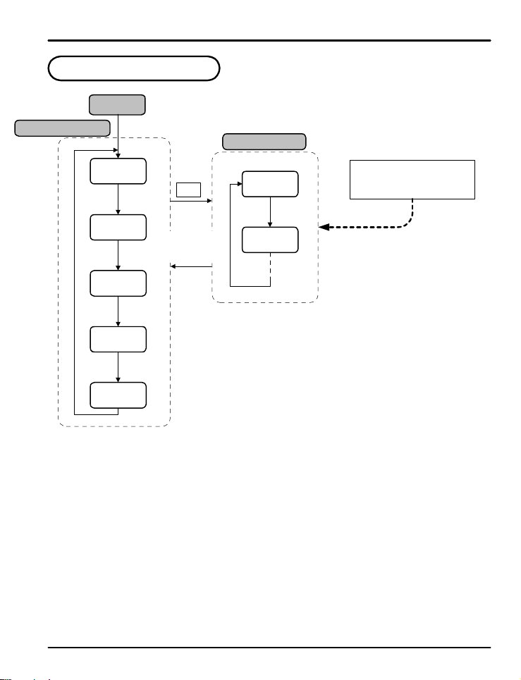
4. Operation Fl ow Ch a rt
Power On
Operation D i s p l ay
Group Dis p l ay
PV Valu e
SP Valu e
OUT
ON/OFF
TIME
**.**
ENT
ENT
ENT
(note 2)
(note 3)
PWD(note 1)
ENT 3 Sec
ENT key for
3 seconds or
no keystroke
for 60 sec
G.CTL
T
G.IN
S or T
HI
**.**
(note 4)
ENT
LO
**.**
(note 5)
note 1 :Initial disp la y at startup.
note 2:Output status f o r t h e l at c h i n g relay.
note 3 :The time that has passed since the PV last went over limit.
note 4:Highest PV value. U se d o n l y wh e n H I.LO paramete r i s se t t o H IGH.
note 5 :Lowest PV. Used only when HI.LO parameter is set to Low.
When setting unit parameters,
G.IN should b e se t u p p r i o r t o
any other parameters.
13

PD570 Series Nova Process and Temperature Limit Controller Instruction Manual
5. Controller Parameter Setup
5.1 Input Group (G.IN)
PV
G.IN
!
CAUTION
PV
In-t
Input group parameters should be established first, as changes to the input type may reset other
parameter settings in o t h e r g roups to their default value.
Press SET/ENT key t o sel e c t input group. Pr e s s pre s s S or T key to cycle t hr o u g h
gro u p s a s sh o wn b e l o w. (Refer to p a r a me t e r ma p in s e ct i o n 3 .)
This parameter sele ct s t h e t y p e o f i nput sensor used. Its default setting is type TC.K1.
Refer to the fo l l o win g t a b l e s h o wi ng t h e t ype o f se n s o r i np u t s a n d se l e ct t h e d e s ired in p u t
type.
Table 1: Universal Input Selection
TYPE
K1
K2
J
E
T
R
B
S
L
N
U
W
PtA
PtB
PtC
JPtA
JPtB
1 to 5V
Temp.Range(ºC)
-200 to 1370
-199.9 to 999.9
-199.9 to 999.9
-199.9 to 999.9
-199.9 to 400.0
-199.9 to 900.0
-200 to 1300
-199.9 to 400.0
-199.9 to 850.0
-199.9 to 500.0
-19.99 to 99.99
-199.9 to 500.0
-150.0 to 150.0
No.
1
2
3
4
5
6
7
8
9
10
11
12
Platinel II
13
14
15
16
17
18
0.4 to 2.0 V
19
20
0 to 10 V
21
-10 to 20m V
22
0 to 100mV
23
4-20 mA Input Selection:
?
To accept a 4-20 mA signal, select 0.4 to 2.0 VDC input and connect a 100 Ω resistor across the input terminals.
NOTE
ST ST
PWD Q G.CTL Q G.IN
K R
G.COM Q G.RET Q G.ALM
ST ST
Temp.Range(ºF)
-300 to 2500
0 to 2300
-300 to 2300
-300 to 1800
0 to 1700
0 to 1800
0 to 1700
0 to 2300
0 to1390
-10.00 to 20.00mV
-300 to 750
32 to 3100
32 to 3300
32 to 3100
-300 to 1600
-300 to 2400
-300 to 750
32 to 4200
32 to 2500
-300 to 1560
-199.9 to 999.9
-4.0 to 212.0
-199.9 to 999.9
-199.9 to 300.0
0.400 to 2. 000V
1.000 to 5. 000V
0.00 to 10. 0 0 V
0.0 to 100.0mV
STT
display range : -5% to 105%
Group
DISP
TC.t1
TC.t2
1
1
TC.J
TC.E
TC.T
TC.R
Thermocouple
TC.B
TC.S
TC.L
TC.N
TC.U
TC.y
-
TC.PL
RTD
(0.00385)
RTD
(0.00392)
VDC
mVDC
PTA
PTB
PTC
JPTA
JPTB
2v
5v
10v
20Nv
100n
-
-
-
-
n
-
-
14
 Loading...