

Page 1
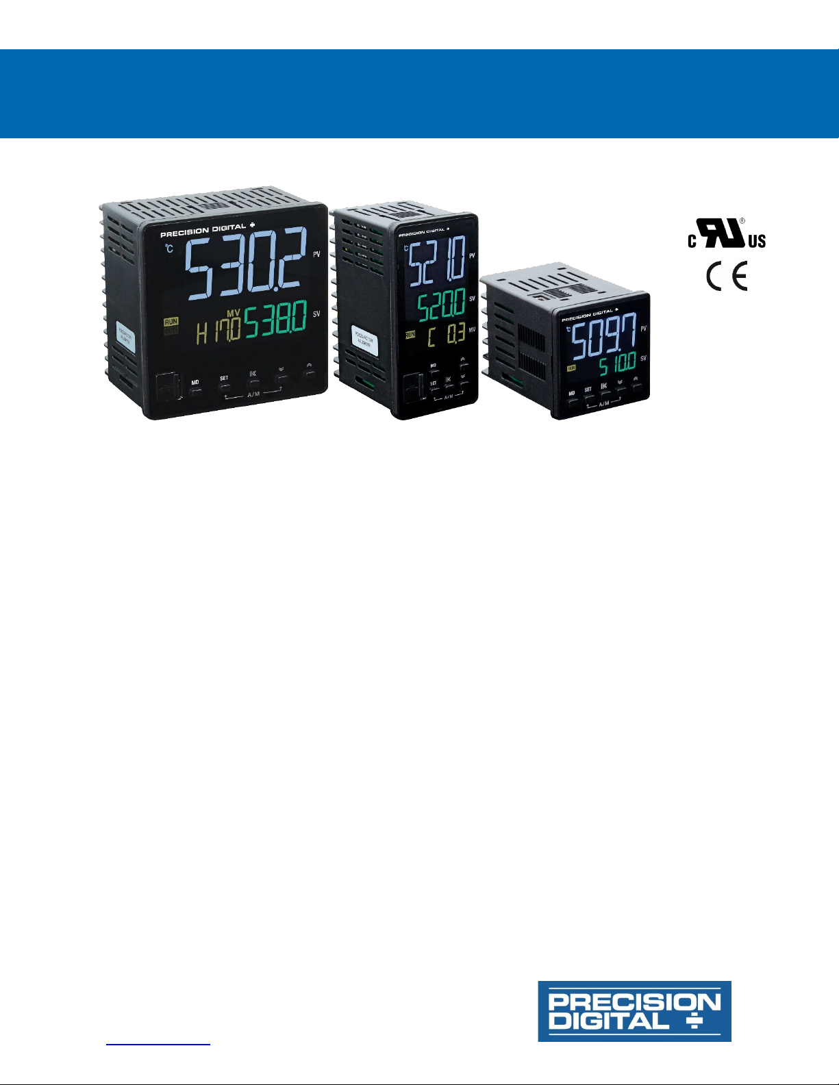
SuperNova PD500 PID Process & Temperature Controllers
PRECISION DIGITAL CORPORATION
www.predig.com
Instruction Manual
• 1/16, 1/8, and 1/4 DIN Auto-Tuning PID Process & Temperature Controllers
• Thermocouple and RTD Inputs
• DC Voltage and Current Inputs (1-5 V, 0-5 V, 0-10 V, 0-50 mV, 0-100 mV; 4-20 mA with Resistor)
• 250 Ω Resistor(s) Included Standard
• High Accuracy Auto-Tuning PID
• High Durability Front with Hard Plastic Pushbuttons
• Large Easy to Read 14-Segment PV Display up to 1.1" (29 mm)
• Input Power 100-240 VAC
• Heating, Cooling, and Heating & Cooling Control
• Primary Control Output Options: 4-20 mA (SCR), Voltage Pulse (SSR), or Relay
• Secondary Control Output Relay Standard on All Models
• Easily Switch Between Auto and Manual Control Modes
• Up to 2 Alarm Relays & 4-20 mA Retransmit Outputs
• Remote Set Value 1-5 V Input Option (4-20 mA with External Resistor)
• Digital Input Set Value Selection
• RS-485 Serial Communications Option
• Modbus® RTU/ASCII Communications
• Mini-USB Port Standard
• FREE Programming and Monitoring Software
• 1/16, 1/8, 1/4 DIN Sizes Available
• Shallow Depth Case Extends Only 2.5" (63 mm) Behind Panel
• IP65 Fronts
• UL & C-UL Recognized Process Control Equipment, Electrical - Component
233 South Street • Hopkinton MA 01748 USA
Tel (800) 343-1001 • Fax (508) 655-8990
Page 2
SuperNova PD500 PID Process & Temperature Controllers
Disclaimer
The information contained in this document is
subject to change without notice. Precision Digital
makes no representations or warranties with
respect to the contents hereof and specifically
disclaims any implied warranties of
merchantability or fitness for a particular purpose.
See Warranty Information and Terms &
Conditions on www.predig.com
details.
• Read complete instructions prior to installation
and operation of the controller.
for complete
Instruction Manual
• Risk of electric shock or personal injury.
• This product is not recommended for life support
applications or applications where malfunctioning
could result in personal injury or property loss.
Anyone using this product for such applications
does so at his/her own risk. Precision Digital
Corporation shall not be held liable for damages
resulting from such improper use.
WARNING
Cancer and Reproductive Harm - www.P65Warnings.ca.gov
Operation & Care Notes
Limited Warranty
Precision Digital Corporation warrants this
product against defects in material or
workmanship for the specified period under
“Specifications” from the date of shipment from
the factory. Precision Digital’s liability under this
limited warranty shall not exceed the purchase
value, repair, or replacement of the defective unit.
See Warranty Information and Terms &
Conditions on www.predig.com
details.
Registered Trademarks
All trademarks mentioned in this document are
the property of their respective owners.
© 2021 Precision Digital Corporation.
All rights reserved.
for complete
2
Page 3

SuperNova PD500 PID Process & Temperature Controllers
Table of Contents
Introduction ......................................................................................................... 6
Abbreviations ................................................................................................. 6
General Controller Term Descriptions .......................................................... 6
Range and Scale Descriptions ..................................................................... 6
Engineering Unit Descriptions ...................................................................... 7
Ordering Information .......................................................................................... 8
Enclosures ...................................................................................................... 9
Accessories .................................................................................................... 9
Specifications ................................................................................................... 10
General .......................................................................................................... 10
Process Input ............................................................................................... 10
Temperature Input ........................................................................................ 11
Control Outputs ............................................................................................ 11
Alarm Relay Outputs .................................................................................... 12
4-20 mA Retransmit Output ......................................................................... 12
Remote SV Process Input ............................................................................ 12
USB Connection ........................................................................................... 12
Digital Inputs ................................................................................................ 12
Modbus® RTU Serial Communications ...................................................... 13
SuperNova TCS Software ............................................................................ 13
Compliance Information................................................................................... 14
Safety ............................................................................................................ 14
Electromagnetic Compatibility .................................................................... 14
Safety Information ............................................................................................ 14
Operation & Care Notes ............................................................................... 15
Installation......................................................................................................... 15
Unpacking ..................................................................................................... 15
Panel Mounting Instructions ....................................................................... 16
Controller Dimensions ................................................................................ 17
Connections ................................................................................................. 18
Connectors Labeling .................................................................................. 18
Power Connections .................................................................................... 19
Signal Connections .................................................................................... 19
Relay Connections ..................................................................................... 19
4-20 mA Output Connections ..................................................................... 20
Digital Input Connections ........................................................................... 20
Remote SV Input Connections ................................................................... 20
Modbus RTU Serial Communications ........................................................ 20
Digital Input Connections ........................................................................... 20
Controller Operation ........................................................................................ 21
Change Control Set Value (SP) ................................................................. 21
RUN/STOP Modes ..................................................................................... 21
Menu Timeout ............................................................................................ 21
Front Panel ................................................................................................ 21
Front Panel Buttons and Status Indicators ................................................ 22
Setup and Programming .................................................................................. 23
Overview ....................................................................................................... 23
Setting Up the Controller ............................................................................. 23
Programming the Controller ....................................................................... 24
Set Value Group (G.SV) ............................................................................ 24
G.SV Parameter Details ............................................................................. 24
Input Group (G.IN) ..................................................................................... 25
G.IN Parameter Details .............................................................................. 26
Output Group (G.OUT) .............................................................................. 27
Output Limit High (OL-H) and Low (OL-L).................................................. 28
G.OUT Parameter Details .......................................................................... 29
Settings Group (G.SET) ............................................................................. 30
Power-On Operation Mode (POOM) .......................................................... 30
G.SET Parameter Details........................................................................... 31
Communication Group (G.COM) ................................................................ 32
Instruction Manual
3
Page 4

SuperNova PD500 PID Process & Temperature Controllers
G.COM Parameter Details ......................................................................... 33
Sub Relay Group (G.SUB) ......................................................................... 34
G.SUB Parameter Details .......................................................................... 36
Transmit & Remote Group (G.TRS) ........................................................... 37
G.TRS Parameter Details .......................................................................... 38
Alarm Group (G.ALM) ................................................................................ 39
G.ALM Parameter Details .......................................................................... 43
Control Group (G.CTL) .............................................................................. 44
G.CTL Parameter Details ........................................................................... 47
SuperNova TCS Software ................................................................................ 49
Remote Programming .................................................................................. 49
Data Acquisition ........................................................................................... 49
Monitoring ..................................................................................................... 49
Monitoring with RS-485 Connection ........................................................... 49
SuperNova TCS Installation ........................................................................ 49
Running SuperNova TCS the First Time......................................................... 50
SuperNova TCS Main menu ........................................................................ 50
Top Level Menus .......................................................................................... 50
Troubleshooting Tips ....................................................................................... 52
Error Messages ............................................................................................ 53
Modbus Register Tables .................................................................................. 54
Fixed Modbus Tables ................................................................................... 54
General Process and Indication, Address 0 - 99 ........................................ 54
Set Value Group (G.SV), Address 100 - 199 ............................................. 54
Control Group (G.CTL), Address 200 - 299 ............................................... 55
Alarm Group (G.ALM) Address, 300 - 399 ................................................. 56
Transmit Group (G.TRS), Address 400 - 499............................................. 56
SUB Relay Group (G.SUB), Address 500 - 599 ......................................... 57
Communication Group (G.COM), Address 600 - 699 ................................ 57
Set Value Group (G.SET), Address 700 - 799 ........................................... 57
Output Group (G.OUT), Address 800 - 899) .............................................. 58
Input Group (G.IN), Address 900 - 999 ...................................................... 58
User Defined Modbus Map .......................................................................... 58
Modbus Register Bit Information ................................................................ 59
Register Bit Assignment ............................................................................. 59
Bit Definitions ............................................................................................. 59
EU Declaration of Conformity .......................................................................... 61
Instruction Manual
4
Page 5

SuperNova PD500 PID Process & Temperature Controllers
Table of Figures
Figure 1. Panel Cutout Dimensions ................................................................ 16
Figure 2. PD510 Mounting Bracket Installation .............................................. 16
Figure 3. PD520 and PD530 Mounting Bracket Installation .......................... 16
Figure 4. Controller Dimensions ..................................................................... 17
Figure 5. Recommended Terminal Connectors ............................................. 18
Figure 6. PD510 Connector Diagram .............................................................. 18
Figure 7. PD520 & PD530 Connector Diagram ............................................... 18
Figure 8. PD510 Power Connection ................................................................ 19
Figure 9. PD520 & PD530 Power Connection ................................................. 19
Figure 10. PD510 Signal Connection .............................................................. 19
Figure 11. PD520 & PD530 Signal Connection ............................................... 19
Figure 12. PD510 Relay Connections ............................................................. 19
Figure 13. PD520 & PD530 Relay Connections .............................................. 19
Figure 14. PD510 4-20 mA Retransmit Connections ..................................... 20
Figure 15. PD520 & 530 4-20 mA Retransmit Connections ........................... 20
Figure 16. PD510 Digital Input Connections .................................................. 20
Figure 17. PD520 & PD530 Digital Input Connections ................................... 20
Figure 18. PD510 Remote SV Input Connections .......................................... 20
Figure 19. PD520 & PD530 Remote SV Input Connections ........................... 20
Figure 20. PD510 RS-485 Connection ............................................................. 20
Figure 21. PD520 & PD530 RS-485 Connection ............................................. 20
Figure 22. Front Panel Buttons and Indicators .............................................. 22
Figure 23. Input Type and Range Selection ................................................... 25
Figure 24. Heating & Cooling Hysteresis........................................................ 28
Figure 25. Alarm Operation when ON & OFF Time delays are Set ............... 34
Figure 26. Alarm Type and Number Table ...................................................... 39
Figure 27. Alarm Operation Description Table ............................................... 40
Figure 28. High Absolute Alarm Operation .................................................... 41
Figure 29. High Absolute Alarm Operation without Standby........................ 41
Figure 30. High Absolute Alarm Operation with Standby ............................. 41
Figure 31. High Absolute Alarm with Latch Function ................................... 41
Figure 32. Loop Break Alarm (LBA) Operation in Reverse Action Mode ..... 42
Figure 33. Standard and Low PV Auto-Tuning SV ......................................... 45
Figure 34. Response Adjustment with Alpha ................................................. 46
Figure 35. Set Value Ramp Up ......................................................................... 46
Figure 36. Set Value Ramp Down .................................................................... 46
Instruction Manual
5
Page 6

SuperNova PD500 PID Process & Temperature Controllers
Instruction Manual
Introduction
The SuperNova PD500 Series of PID Process & Temperature Controllers is a complete line of PID and on/off
controllers. Available in popular 1/4, 1/8, and 1/16 DIN sizes, and with a shallow depth behind panel of only 2.5"
(63 mm) it is easy to fit into almost any panel, product, or enclosure.
Voltage, current (with external resistor), and direct temperature thermocouple and RTD inputs make it an excellent
choice for any control application requiring easy to change, visible set points.
This modern line of controllers shows the process variable (PV), set value (SV), and manipulated value (output
level%, MV) on a striking reverse polarity LCD screen. Indicators for units (˚C, ˚F,%, or none)
Auto and manual control modes can be easily changed by holding two buttons, and this is indicated on the front panel
to make it easy for operators to know how to use this feature.
Main control outputs can be 4-20 mA (SCR), voltage pulse (SSR), or relay outputs. A secondary relay control output
is standard, which allow for one or two direction SV control (i.e., heating and cooling).
Additional outputs may include two SPST alarm relays and a 4-20 mA retransmit output. Other options include a
secondary 4-20 mA input to remotely control the set point, and RS-485 for Modbus communication.
A mini-USB port may be used for a direct PC connection to run the SuperNova software for monitoring, programming,
and data logging. This USB port is located on the rear behind the panel for PD510 1/16 DIN models, and on the front
behind a rubber tab on PD520 and PD530 1/8 and 1/4 DIN models.
Abbreviations
The following abbreviations are used throughout this manual.
General Controller Term Descriptions
Abbreviation Full Meaning
PV Process value
SV Set value
MV Manipulated value (Output value %)
AT Auto-tuning
REM Remote set value
RET Retransmission 4-20 mA output
SUB1 SUB1 output (alarm relay 1)
SUB2 SUB2 output (alarm relay 2)
LBA Loop break alarm
EU Engineering unit
EUS Engineering unit, total span
Range and Scale Descriptions
FR.L Full Range Low: The temperature range is defined according to the thermocouple or RTD type selected.
The minimum temperature value of this range is referred to as the FR.L (full range, low).
Example: For a type K thermocouple, the FR.L is -200 °C.
FR.H Full Range High: The temperature range is defined according to the thermocouple or RTD type
selected. The maximum temperature value of this range is referred to as the FR.H (full range, high).
Example: For a type K thermocouple, the FR.H is 1370 °C.
SL.L Scale Limit Low: The scale range is used when the input is a process signal, voltage or current (with an
external sense resistor). The minimum scale value of the process input is referred to as the SL.L. This
value may be changed with the SL-L parameter to scale the process input to the desired engineering
unit.
Example: For a 1 to 5 VDC input, the default SL.L is -1999. To represent an input value of 0 to 100%,
the SL-L parameter would be changed to 0, making the SL.L 0.
SL.H Scale Limit High: The scale range is used when the input is a process signal, a voltage or current (with
an external sense resistor). The maximum scale value of the process input is referred to as the SL.H.
This value may be changed with the SL-H parameter to scale the process input to the desired
engineering unit.
Example: For a 1 to 5 VDC input, the default SL.H is 9999. To represent an input value of 0 to 100%,
the SL-H parameter would be changed to 100, making the SL.H 100.
6
Page 7
SuperNova PD500 PID Process & Temperature Controllers
Instruction Manual
Engineering Unit Descriptions
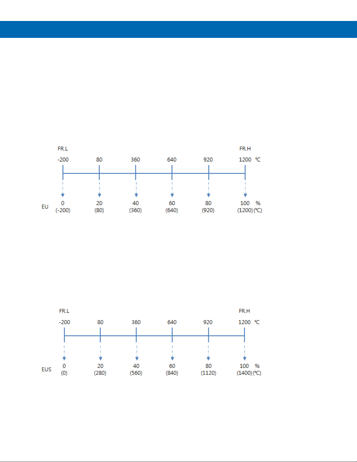
During the programming of the controller, there are two types of engineering units referred to, EU, and EUS.
EU: The value in engineering units according to the input range.
EUS: The value in engineering units according to the full span of the input.
Engineering Units (EU)
A parameter or other value defined in EU is defined in the actual absolute engineering unit value of the input type (or
scaled engineering units for the case of voltage or current inputs).
This means the EU value takes on the actual engineering unit value, which may be negative in some cases.
In the example below, the controller has been programmed for a type J thermocouple. A type J thermocouple has a
range of -200°C (FR.L) to 1200°C (FR.H). Any parameter or value using EU unit definitions could be defined in values
from -200°C to 1200°C.
If the parameter or value is defined in EU, but listed as a percentage (EU %), 0% represents the value of -200°C and
100% represents a value of 1200°C.
Engineering Unit Span (EUS)
A parameter or other value defined in EUS is defined in the actual engineering units of the input type (or scaled
engineering units for the case of voltage or current inputs) but represents the span value in those engineering units.
This means the EUS value is defined in engineering units, but begins at 0, representing the low range of input (FR.L
or SL.L) and will not be a negative value, regardless of the actual input range.
In the example below, the controller has been programmed for a type J thermocouple. A type J thermocouple has a
range of -200°C (FR.L) to 1200°C (FR.H), but a span of 1400°C. Any parameter or value using EUS unit definitions
could be defined in values from 0°C to 1400°C.
If the parameter or value is defined in EUS, but listed as a percentage (EUS %), 0% represents the value of 0°C and
100% represents a value of 1400°C.
7
Page 8

SuperNova PD500 PID Process & Temperature Controllers
Model Number
DIN Size
Main Control Output
Additional Features
PD510-A
1/16
4-20 mA (SCR)
Relay Control Output, 2 Alarm Relays
PD510-A-CD
1/16
4-20 mA (SCR)
Relay Control Output, 2 Alarm Relays, RS-485, 2 Digital Inputs
PD510-A-CTR
1/16
4-20 mA (SCR)
Relay Control Output, 2 Alarm Relays, RS-485, 4-20 mA Retransmit, 4-20 mA SV
Input
PD510-S
1/16
Voltage Pulse (SSR)
Relay Control Output, 2 Alarm Relays
PD510-S-CD
1/16
Voltage Pulse (SSR)
Relay Control Output, 2 Alarm Relays, RS-485, 2 Digital Inputs
PD510-S-CTR
1/16
Voltage Pulse (SSR)
Relay Control Output, 2 Alarm Relays, RS-485, 4-20 mA Retransmit, 4-20 mA SV
Input
PD510-R
1/16
Relay (On/Off)
Relay Control Output, 2 Alarm Relays
PD510-R-CD
1/16
Relay (On/Off)
Relay Control Output, 2 Alarm Relays, RS-485, 2 Digital Inputs
PD510-R-CTR
1/16
Relay (On/Off)
Relay Control Output, 2 Alarm Relays, RS-485, 4-20 mA Retransmit, 4-20 mA SV
Input
PD520-A
1/8 (V)
4-20 mA (SCR)
Relay Control Output, 2 Alarm Relays
PD520-A-CTD
1/8 (V)
4-20 mA (SCR)
Relay Control Output, 2 Alarm Relays, RS-485, 4-20 mA Retransmit, 2 Digital
Inputs
PD520-A-CTDR
1/8 (V)
4-20 mA (SCR)
Relay Control Output, 2 Alarm Relays, RS-485, 4-20 mA Retransmit, 2 Digital
Inputs, 4-20 mA SV Input
PD520-S
1/8 (V)
Voltage Pulse (SSR)
Relay Control Output, 2 Alarm Relays
PD520-S-CTD
1/8 (V)
Voltage Pulse (SSR)
Relay Control Output, 2 Alarm Relays, RS-485, 4-20 mA Retransmit, 2 Digital
Inputs
PD520-S-CTDR
1/8 (V)
Voltage Pulse (SSR)
Relay Control Output, 2 Alarm Relays, RS-485, 4-20 mA Retransmit, 2 Digital
Inputs, 4-20 mA SV Input
PD520-R
1/8 (V)
Relay (On/Off)
Relay Control Output, 2 Alarm Relays
PD520-R-CTD
1/8 (V)
Relay (On/Off)
Relay Control Output, 2 Alarm Relays, RS-485, 4-20 mA Retransmit, 2 Digital
Inputs
PD520-R-CTDR
1/8 (V)
Relay (On/Off)
Relay Control Output, 2 Alarm Relays, RS-485, 4-20 mA Retransmit, 2 Digital
Inputs, 4-20 mA SV Input
PD530-A
1/4
4-20 mA (SCR)
Relay Control Output, 2 Alarm Relays
PD530-A-CTD
1/4
4-20 mA (SCR)
Relay Control Output, 2 Alarm Relays, RS-485, 4-20 mA Retransmit, 2 Digital
Inputs
PD530-A-CTDR
1/4
4-20 mA (SCR)
Relay Control Output, 2 Alarm Relays, RS-485, 4-20 mA Retransmit, 2 Digital
Inputs, 4-20 mA SV Input
PD530-S
1/4
Voltage Pulse (SSR)
Relay Control Outputs, 2 Alarm Relays
PD530-S-CTD
1/4
Voltage Pulse (SSR)
Relay Control Output, 2 Alarm Relays, RS-485, 4-20 mA Retransmit, 2 Digital
Inputs
PD530-S-CTDR
1/4
Voltage Pulse (SSR)
Relay Control Output, 2 Alarm Relays, RS-485, 4-20 mA Retransmit, 2 Digital
Inputs, 4-20 mA SV Input
PD530-R
1/4
Relay (On/Off)
Relay Control Output, 2 Alarm Relays
PD530-R-CTD
1/4
Relay (On/Off)
Relay Control Output, 2 Alarm Relays, RS-485, 4-20 mA Retransmit, 2 Digital
Inputs
PD530-R-CTDR
1/4
Relay (On/Off)
Relay Control Output, 2 Alarm Relays, RS-485, 4-20 mA Retransmit, 2 Digital
Inputs, 4-20 mA SV Input
Ordering Information
Instruction Manual
8
Page 9
SuperNova PD500 PID Process & Temperature Controllers
Model/Series
Meters
DIN
Material
PDA2301-V
1
1/8 (V)
Plastic NEMA 4X
PDA2302-V
2
1/8 (V)
Plastic NEMA 4X
PDA2303-V
3
1/8 (V)
Plastic NEMA 4X
PDA2304-V
4
1/8 (V)
Plastic NEMA 4X
PDA2305-V
5
1/8 (V)
Plastic NEMA 4X
PDA2306-V
6
1/8 (V)
Plastic NEMA 4X
PDA2301-4
1
1/4
Plastic NEMA 4X
PDA2301-16
1
1/16
Plastic NEMA 4X
Plastic NEMA 4X
with Clear Cover
Stainless Steel
NEMA 4X
Painted Steel
NEMA 4
Model
Description
250 Ω 0.1% Precision Resistor for
SuperNova 4-20 mA Input
PDA7485-I
RS-232 to RS-485 isolated converter
PDA8485-I
USB to RS-485 isolated converter
PD9501
Multi-function calibrator
PDA-LH
Light / horn accessory
MOD-LH
Light / horn / enclosure modification
PDAMINIUSB
USB Cable for SuperNova Series, Type
A Male to Type Mini-B Male
PDX6901
Snubber: 0.01 μF/470 Ω, 250 VAC
Signal Isolator with One 4-20 mA
Signal Splitter with One 4-20 mA
Signal Conditioner with One 0-10
VDC Input and One 4-20 mA Output
Signal Conditioner with One 4-20
Instruction Manual
Enclosures
PDA3408 1 1/4
PDA2600 1-6 1/8 (V)
PDA2700 1-6 1/8 (V)
Accessories
PDX-RES2
Signal Splitter & Conditioner Accessories
Model Description
PD659-1MA-1MA
PD659-1MA-2MA
PD659-1V-1MA
Input and One 4-20 mA Output
Input and Two 4-20 mA Outputs
Need help selecting the right enclosure?
Go to www.predig.com/esu
PD659-1MA-1V
mA Input and One 0-10 VDC Output
9
Page 10
SuperNova PD500 PID Process & Temperature Controllers
Controller with rubber gasket and
remote setpoint input option.
Strength
Operating temperature range:
Storage temperature range:
Case extends 2.5 in (63 mm) behind
UL Recognized, 250 VAC 0.5 A max,
with IEC60947-1 or IEC60947-3
Selection
Input Accuracy
Input Type
Prog.
No.
Display
Scale Range
Accuracy
4-20 mA*
30
1-5
-1999 to 9999
±0.2% of FS
1-5 V
30
1-5
0-5 V
31
5V
0-10 V
32
10V
0-50 mV
33
0.05V
0-100 mV
34
0.1V
Specifications
Except where noted all specifications apply to
operation at +25°C.
General
Display
Display Height inches (mm)
PV SV MV
PD510 0.60 (15.2) 0.29 (7.4) N/A
PD520 0.81 (20.5) 0.50 (12.8) 0.37 (9.3)
PD530 1.14 (29.0) 0.59 (15.0) 0.43 (11.0)
PV Display
Update Rate
Non-Volatile
Memory
Included
Components
Wide viewing angle reverse polarity
LCD; PV: white, SV: green, MV: amber
PD510: PV and SV display
PD520: PV, SV, and MV display
PD530: PV, SV, and MV display
4/second (250 ms)
Settings stored for a minimum of
10 years.
EEPROM life: 1 million writes
mounting bracket, 250 Ω resistor (1%),
and Quick Start Guide. Additional 250 Ω
resistor (1%) provided for models with
Process Input
Process Input
Process Input
Decimal Point Up to 3 decimals.
Input Sampling
*To achieve the highest accuracy with a 4-20 mA input to the
controller, connect a 250 Ω (0.1% or higher precision) resistor across
the input terminals. The 250 Ω (1%) resistor included with the product
is not a precision resistor. For precision resistor, order PDX-RES2.
Instruction Manual
Voltage or current (with external
resistor)
1-5 V (4-20 mA), 0-5 V, 0-10 V,
0-50 mV, 0-100 mV
External 250 Ω resistor required to read
4-20 mA. Recommended accessory
PDX-RES2.
20 samples/sec (50 ms per sample).
For display update rate, see Display
Update Rate
± 1 digit
EEPROM Lock
Power
Insulation
Resistance
Dielectric
Environmental
Front Panel
Depth Behind
Panel
Required Fuse
Connections
Mounting
Weight PD510: 4.2 oz (120 g)
Warranty
Programmable lock or unlock write
access to the EEPROM. When locked,
setting changes stored in RAM (not
saved on power down).
100 - 240 VAC ±10%, 50 / 60 Hz
8.5 VA max.
20 MΩ minimum, 500 VDC
3,000 VAC; 50/60 Hz for 1 minute
across power terminals
-10 to 50°C (14 to 122°F)
-25 to 65°C (-40 to 185°F)
Relative humidity:
35 to 85% non-condensing
IP65
panel.
slow-blow fuse.
Use fuses or circuit breakers compliant
Fixed rear screw terminals and
mini-USB
1/4, 1/8, or 1/4 DIN panel cutout
required: panel mounting bracket
assemblies are provided.
PD520: 7.1 oz (202 g)
PD530: 10.2 oz (290 g)
1 year parts & labor. See Warranty
Information and Terms & Conditions on
www.predig.com
for complete details.
10
Page 11
SuperNova PD500 PID Process & Temperature Controllers
Input Selection
Type
Input
Type
Prog.
No.
Display
Range
Accuracy
-200 to 1370°C
2
K1
-148 to 932°F
-100.0 to 500.0°C
-200 to 1200°C
4
J1
-328 to 1652°F
-199. To 900.0°C
E 5 E1
-328 to 1652°F
-199.9 to 400.0°C
R 7 R0
32 to 3092°F
0 to 1700°C
± 1 digit
0 to 1700°C
L
10
L1
-328 to 1652°F
-199.9 to 900.0°C
-200 to 1300°C
U
12
U1
-328 to 752°F
-199.9 to 400.0°C
W
13
W0
32 to 4172°F
0 to 1300°C
JPt100
20
JPt0
-328 to 932°F
-200 to 500°C
Pt100
22
Pt0
-328 to 1184°F
-200 to 640°C
23
Pt1
-328 to 1184°F
Temperature Input
Temperature
Thermocouple
RTD Type JPT100, PT100
Cold Junction
Compensation
(RJC)
RTD Max Line
Resistance
Input Sampling
Input Accuracy
K 1 K0 -328 to 2498°F
J 3 J0 -328 to 2192°F
T 6 T1 -328 to 752°F
Field programmable for thermocouple
or RTD
K, J, E, T, R, B, S, L, N, U, W, PLII
±1.5°C (-10 to 50°C)
Three wire RTD with identical line
resistance up to 10 Ω
20 samples/sec (50 ms per sample).
For display update rate, see Display
Update Rate
-199.9 to 900.0°C
±0.2% of FS
± 1 digit
Control Outputs
Control
Outputs
Main Control
Output
Control Type ON/OFF, PID control
Output
Operation
Current SCR
Output
Voltage Pulse
SSR Output
Relay Output
Each controller has a main control output
and a secondary control relay output for
two directions of control. The secondary
control relay output is always used for
On/Off operation.
4-20 mA output (SCR), voltage pulse
(SSR), or electromechanical relay (On/Off)
outputs available.
Programmable for reverse or direct action.
4-20 mA linear current output
Load resistance: 600 Ω maximum
± 0.2% of FS ± 1 digit
12 V ± 1 VDC
Load resistance: 600 Ω minimum
Recommended minimum cycle time: 1 sec
Rated resistive load switching capacity:
5 A, 250 VAC; 5 A, 30 VDC
Max switching power: 750 VA, 90 W
Max switching voltage: 250 VAC, 110 VDC
Max switching current: 5 A
Mechanical life: 20 million cycles (at 180
CPM)
Recommended minimum cycle time: 20 sec
Instruction Manual
B 8 B0 212 to 3272°F
100 to 1800°C
S 9 S0 32 to 3092°F
N 11 N0 -328 to 2372°F
0 to 2300°C
PLII 14 PL0 32 to 2372°F
21 JPt1 -328 to 932°F
-199.9 to 500.0°C
-199.9 to 640.0°C
±0.2% of FS
± 1 digit
100 to 200°C:
±2.0% of FS
±0.2% of FS
± 1 digit
11
Page 12
SuperNova PD500 PID Process & Temperature Controllers
Ratings
Automatic, front panel button, in setup
communications
0 to 999 seconds, on and off delays;
programmable for each SUB relay.
Programmable, independent for each
failure, relays will go to alarm state.
Operation
Programming, independent for each
Function
Input Accuracy
Function
Communication
Cable
Input Current
Alarm Relay Outputs
Function
Number
Alarm Relay
Deadband 0-100% FS, user selectable
High or Low
Alarm
Absolute or
Deviation Alarm
Loop Break
Alarm
Alarm Relay
Operation
Relay Reset
(Acknowledge)
Time Delay
Fail-Safe
Operation
Standby
Auto
Initialization
Programmable for 13 different alarm
types or off.
Two alarm relays standard on all
models.
Rated resistive load switching capacity:
5 A, 250 VAC; 5 A, 30 VDC
User may program any alarm for high,
low, or high-low range operation.
User may program any alarm as an
absolute value alarm or a set value
deviation alarm.
User may program any SUB alarm relay
as a loop break alarm.
• Automatic (non-latching)
and/or manual reset
• Latching (requires manual
acknowledge) with/without
clear
• Off (disable unused relays)
parameter menu, or through serial
alarm relay. Relay coils are energized in
non-alarm condition. In case of power
alarm relay
When power is applied to the controller,
relays will reflect the state of the input to
the controller unless standby mode is
enabled.
4-20 mA Retransmit Output
Scaling Range 0-100% of full scale
Output Loop
Resistance
Output Accuracy ±0.2% of full scale ± 1 digit
0-10 VDC Output
Remote SV Process Input
Function Process input to remotely change SV
Input Type &
Range
USB Connection
Location PD510: Top, behind panel
Compatibility USB 2.0 Standard, Compliant
Connector Type Mini-USB receptacle
Protocol Protocol: PC-LINK
Communication
Distance
Instruction Manual
4-20 mA linear current output
600 Ω maximum load
The PD659-1MA-1V
optional 4-20 mA output to a 0-10 VDC
output
1-5 V, 4-20 mA
External 250 Ω resistor required to read
4-20 mA.
±0.2% of full scale ± 1 digit
SuperNova software connection only
PD520 & PD530: Front mounted behind
rubber seal, accessible from front panel
UMS (USB Mass Storage) 2.0
USB A Male to Mini-USB Cable
Baud rate: 38400 bps
Start bit: 1 bit
Data bits: 8 bits
Parity bit: None
Stop bit: 1 bit
16.4 ft (5 m) maximum
can convert the
Digital Inputs
Function Digital Input 1: Select Run/Stop Mode
Digital Input 2: Select SV 1 or SV4/REM
Contacts DI1 and DI2, shared common
Logic Levels On: 1.5 V; Off: 0.1 V
Approximately 2 mA each contact
Input
Impedance
Open Contact
Voltage
On : 1 kΩ max, Off: 100 kΩ min.
Open contact voltage approximately
5 VDC
12
Page 13
SuperNova PD500 PID Process & Temperature Controllers
Max Range
Parity
Availability
Download directly from
www.predig.com/download_software
Operating
Requirements
Microsoft® Windows® 7/8/10
Minimum
Pentium 1 GHz
2 GB available hard drive space (x64)
Communications
USB 2.0 (single controller only)
logging of multiple units)
Configuration
Configure parameters of all connected
controllers.
Data Log
Data log onto computer hard drive.
also
.png. Data tables may also be exported
as .csv.
USB Powered
USB port provides power to the
controller operations.
Modbus® RTU Serial
SuperNova TCS Software
Communications
Communication Method
Slave Id
Baud Rate
Start Bit 1 bit
Data Bits Programmable for 7 or 8 bits
Stop Bit Programmable for 1 or 2 bits
Protocol
Response
Time
EIA RS-485 standard, 2-wire half-duplex
with grounded, shielded cable
1 – 99 (Controller address); 31 maximum
bus connections
3,937 ft (1.2 km)
Programmable for 4800, 9600, 14400,
19200, 38400, 57600 bps.
Programmable for none, even, or odd.
PC-LINK STD, PC-LINK SUM, MODBUSASCII, MODBUS-RTU
Actual response time =
processing time + (response time x 50 ms)
System
Hardware
Requirements
Instruction Manual
64-bit (x64) or 32-bit (x86)
512 MB RAM
1 GB available hard drive space (x86)
(Standard USB A to Mini-B USB)
RS-232 to RS-485 converter or
USB to RS-485 converter
(programming, monitoring, and data
Data log files may be exported to
HTML, .xls, .xlsx, or .pdf format as
graphs or data tables. Graphs may
be exported as .bmp, .gif, .jpeg, or
controller for programming.
Apply normal power for general
13
Page 14
SuperNova PD500 PID Process & Temperature Controllers
UL & C-UL
Certified for Canada - Component
UL File Number
E171428
CE Marked
EN 55022
Class A ITE emissions requirements
Electrostatic
Discharge
KN61000-4-2
Electrical Fast
Transients
EFT(RS): KN61000-4-3
Surge
KN61000-4-5
Conductivity RF
(CS)
KN61000-4-6
Compliance Information
Safety Information
Instruction Manual
Safety
USA & Canada
Recognized
Component
Process Control Equipment, Electrical –
Component
Process Control Equipment, Electrical
Electromagnetic Compatibility
Note:
Testing was conducted on controllers installed through
the covers of grounded metal enclosures with cable
shields grounded at the point of entry representing
installations designed to optimize EMC performance.
• Read complete instructions prior to installation
and operation of the controller.
• Install outdoors only with appropriate protection.
• Use it only in the ambient temperature and
humidity ranges indicated in this manual.
• Do not use in locations where corrosive and
flammable gases are present.
• Use it in places where vibrations and impacts are
not directly applied to the unit.
• Use it in places without liquids, oils, chemicals,
steam, dust, salt, iron, etc. (pollution degree 1 or
2).
• Avoid places where large amounts of inductive or
electromagnetic noise or static electricity are
generated.
• Avoid places with heat accumulation caused by
direct sunlight, radiant heat, etc.
• Use it in places with elevation below 2000 m.
• Installation Category II.
• Risk of electric shock or personal injury.
• The input/output terminals are subject to electric
shock risk. Never let the input/output terminals
come in contact with your body or a conductive
material.
• This product is not recommended for life support
applications or applications where malfunctioning
could result in personal injury or property loss.
Anyone using this product for such applications
does so at his/her own risk. Precision Digital
Corporation shall not be held liable for damages
resulting from such improper use.
• This controller is not equipped with a power
switch or fuse, install them separately (fuse
rating: 250 VAC, 0.5 A).
• Supply the rated power voltage to prevent
product damage or malfunction.
• To reduce risk of electric shocks, do not supply
power until all installation wiring is complete.
• Do not connect or disconnect any wiring while the
power terminal wires are live.
• The product has no hazardous area
classifications. Use only in safe areas.
• Never modify, repair, or disassemble this
controller. This may result in electric shock, fire,
or damage to the controller.
• Please use this controller only after installing it to
a panel to reduce risk of shock or injury.
• When used in equipment with a high risk of
personal injury or property damage, installing a
redundant fuse and other safety devices is
recommended.
14
Page 15

SuperNova PD500 PID Process & Temperature Controllers
Operation & Care Notes
• Please do not clean the controller with organic
solvents such as alcohol, benzene, etc. Clean it
with neutral detergents.
• If water enters the unit, a short circuit or fire may
occur, so please inspect the product carefully.
• For thermocouple input, use the predetermined
compensating cable (temperature errors occur
when using ordinary cable).
• For RTD input, use a cable with small lead wire
resistance and without resistance difference
among the 3 wires (temperature errors occur if
the resistance value among the 3 wires is
different).
• Keep the input signal line away from power line
and load line to avoid the influence of inductive
noise.
• The input signal line and the output signal lines
should be separated from each other. If
separation is not possible, use shield wires for
the input signal line.
• Use a non-grounded sensor for thermocouple
(using a grounded sensor may cause
malfunctions).
• When there is a lot of noise from the input power
source, we recommend using an isolation
transformer and noise filter. Please install the
noise filter to a grounded panel or structure and
make the wiring of the noise filter output to the
controller power supply terminal as short as
possible.
• Tightly twisting the power cables helps prevent
noise.
• Be sure to program the alarm functions to behave
as desired in the case of abnormal operation.
Confirm this before operation.
• When replacing the sensor, be sure to turn off the
power to the controller.
• Use an intermediate relay when the frequency of
operation (such as proportional operation) is
high, because connecting the load to the output
relay directly may shorten the life of the
controller. In these cases, using the voltage
pulse/SSR drive output type is recommended.
• When using an electromagnetic relay for control,
set the proportional cycle to at least 20 sec.
• When using SSR output for control, set the
proportional cycle to at least 1 sec.
• Do not wire anything to unused terminals.
• Confirm all terminal polarities before wiring any
inputs or outputs to avoid damage.
• When you install this product to a panel, use
switches or circuit breakers compliant with
IEC60947-1 or IEC60947-3.
• Install switches or circuit breakers at close
distance for easy user accessibility.
• Specify on the panel that, since switches or
circuit breakers are installed, if the switches or
circuit breakers are open, the power will be cut
off.
Installation
There is no need to remove the controller from its
case to complete the installation, wiring, and
setup of the controller.
Unpacking
Remove the controller from box. Inspect the
packaging and contents for damage. Report
damages, if any, to the carrier.
If any part is missing or the controller
malfunctions, please contact your supplier or the
factory for assistance.
Instruction Manual
15
Page 16

SuperNova PD500 PID Process & Temperature Controllers
Panel Cutout
Dimension
PD510
PD520
PD530
W11
45.0
45.0
93.0
H11
45.0
93.0
93.0
A
60.0
70.0
117.0
B
60.02
122.0
117.0
Panel Mounting Instructions
• Prepare the appropriate standard DIN panel
cutout. Refer to Figure 1. Panel Cutout
Dimensions below for more details.
• Clearance: allow at least 3.5" (88.4 mm) behind
the panel for wiring.
• Panel thickness: 0.04" - 0.28" (1.0 mm - 7.0 mm).
• Remove the mounting bracket(s) provided with the
controller.
• Insert controller into the panel cutout.
• Install mounting bracket(s) and tighten the
screws against the panel. To achieve a proper
seal, tighten the mounting bracket screws evenly
until controller is snug to the panel. DO NOT
OVER TIGHTEN, as the rear of the panel may be
damaged. See Figure 2. PD510 Mounting
Bracket Installation
• and Figure 3. PD520 and PD530 Mounting
Bracket Installation.
Figure 2. PD510 Mounting Bracket Installation
Instruction Manual
Units: in (mm)
1.+0.5 mm tolerance applied.
2. Allow 3.9 in (100.0 mm) above controller for use of
a USB cable with PD510.
Figure 1. Panel Cutout Dimensions
Figure 3. PD520 and PD530 Mounting Bracket
Installation
16
Page 17
SuperNova PD500 PID Process & Temperature Controllers
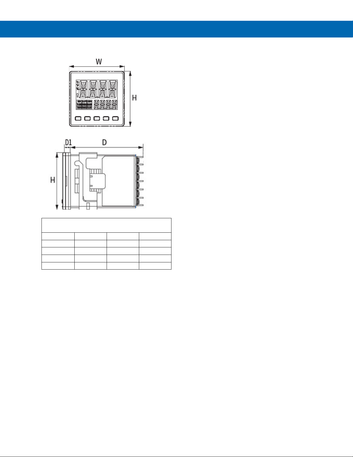
Controller Dimensions
Dimension
PD510
PD520
PD530
W
48.0
48.0
96.0
H
48.0
96.0
96.0
D
63.0
63.0
63.0
D1
5.0
5.0
5.5
Controller Dimensions
Instruction Manual
Units: in (mm)
Figure 4. Controller Dimensions
17
Page 18
SuperNova PD500 PID Process & Temperature Controllers
Connections
All connections are made to non-removable
screw terminal connectors located at the rear of
the controller.
The mini-USB connector is located at the front of
the PD520/PD530 and at the top of the PD510.
• Use copper wire with 60°C or 60/75°C insulation
for all line voltage connections. Observe all safety
regulations. Electrical wiring should be performed
in accordance with all applicable national, state,
and local codes to prevent damage to the
controller and ensure personnel safety.
• Use spade or ring terminals to secure wires.
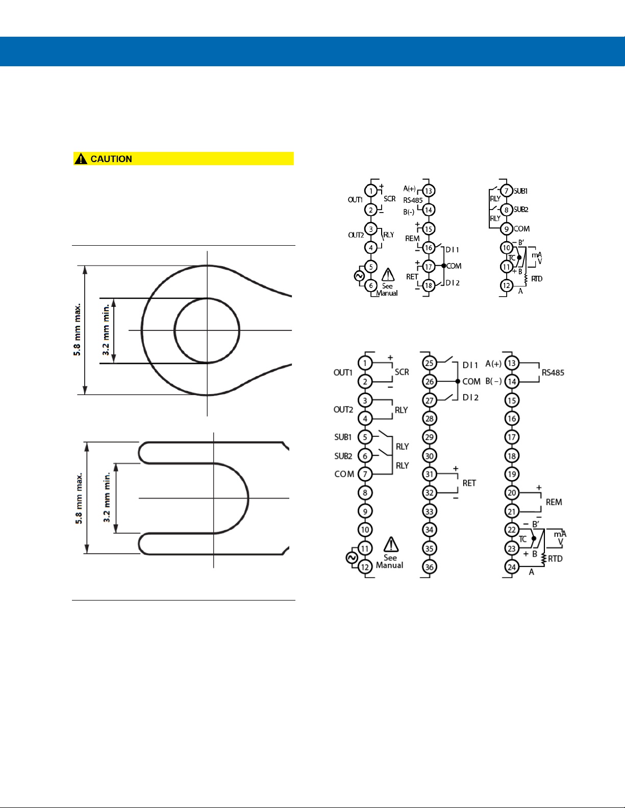
Connectors Labeling
The connector labelling diagraph marked on the
controller shows the location of all connectors
available with requested configuration.
All options are shown in the diagrams below, though
only installed options will appear on a controller.
Figure 6. PD510 Connector Diagram
Instruction Manual
Figure 5. Recommended Terminal Connectors
Figure 7. PD520 & PD530 Connector Diagram
18
Page 19
SuperNova PD500 PID Process & Temperature Controllers
Power Connections
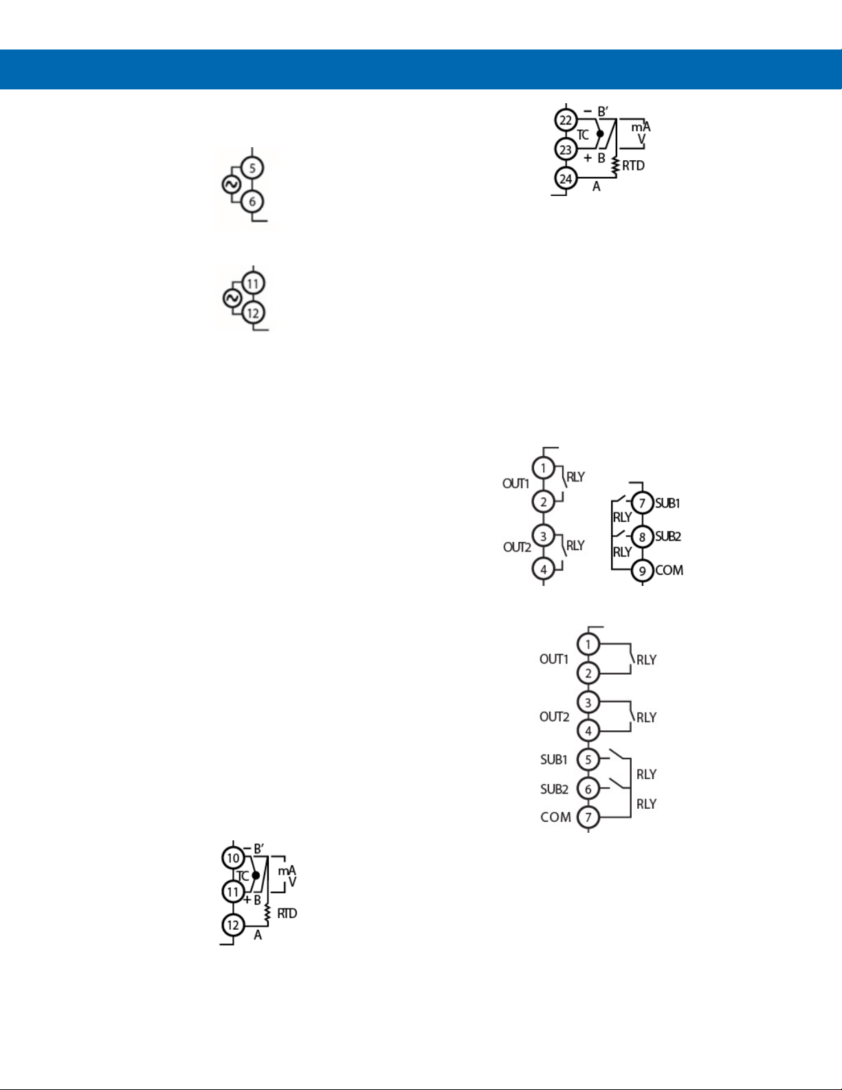
Power connections are made to two terminals.
Figure 8. PD510 Power Connection
Figure 9. PD520 & PD530 Power Connection
Signal Connections
Signal connections are made to a group of three
terminals. Use the labeling appropriate to the desired
input.
Additional setup and programming is performed using
the SuperNova software or through the front panel
buttons.
Figure 11. PD520 & PD530 Signal Connection
Relay Connections
Each controller has 3 or 4 relay outputs, one or two
control relays and 2 alarm relays.
If the controller has a main control relay, OUT1 will be
labelled as a relay (RLY) output. Control output 2 is
always OUT2, and is always a relay (RLY) output.
The alarm relay connections are made to terminals
SUB1 and SUB2.
Each relay is a form A relay with a normally open
(NO) and common (COM) contact. OUT1 and OUT2
are isolated. SUB1 and SUB2 alarm relays share a
common COM contact.
Instruction Manual
Thermocouple
Connect the thermocouple with the positive side to
plus and the negative side (typically red) to minus.
RTD
For a three-wire RTD, connect the single lead to
terminal A. Connect the identical leads to terminal B
and B’ to compensate for lead resistance (typically
identical colors).
Voltage
Connect the positive and negative of the voltage
source device to the positive and negative terminals.
Current
To accept a 4-20 mA input, connect the positive
terminal to + and the negative, return, or common
wire to -. In addition, connect an external 250 Ω
resistor across the + and – terminals.
Figure 12. PD510 Relay Connections
Figure 13. PD520 & PD530 Relay Connections
Figure 10. PD510 Signal Connection
19
Page 20
SuperNova PD500 PID Process & Temperature Controllers
4-20 mA Output Connections
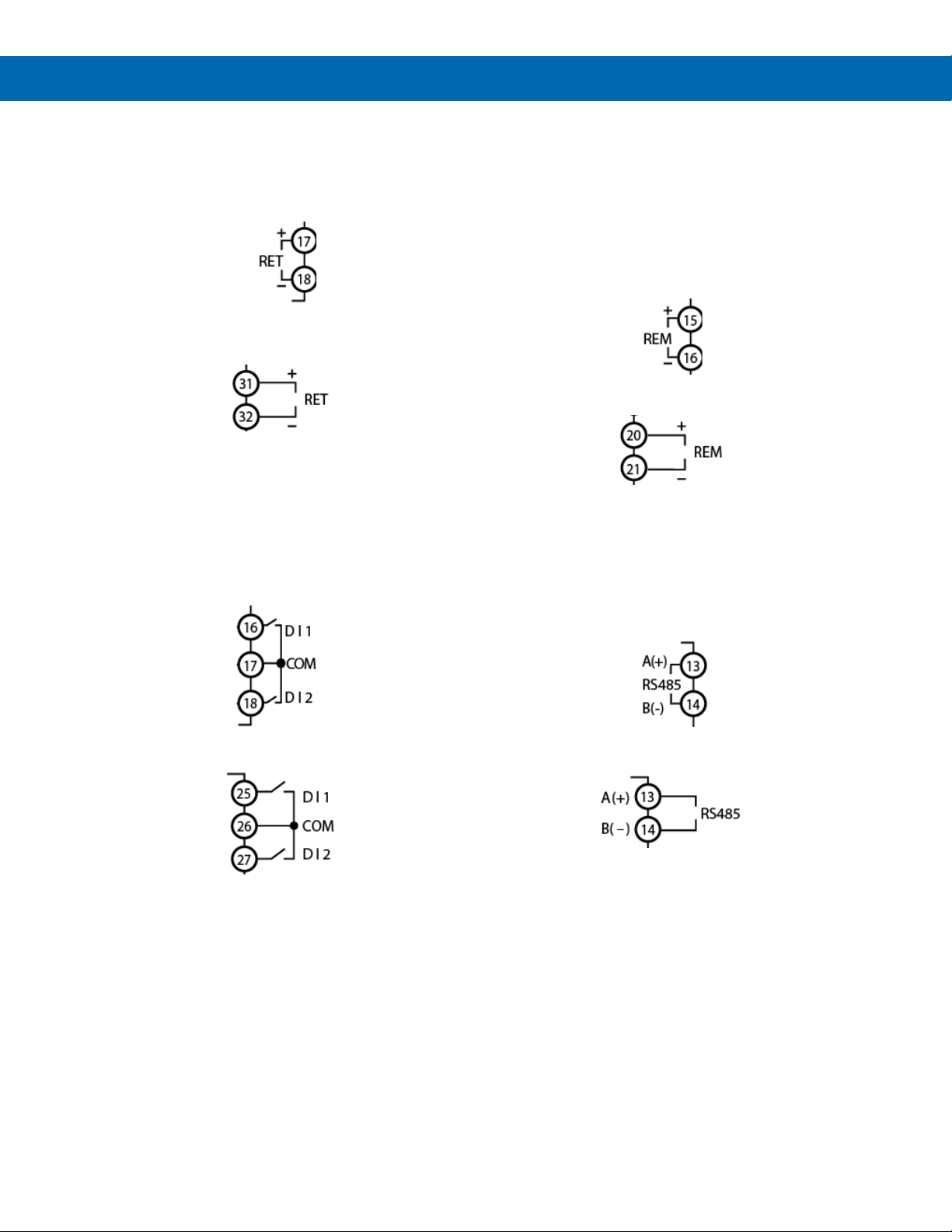
Connections for the 4-20 mA retransmit output are
made to the connector terminals labeled mA OUT.
The 4-20 mA output is an active output, powered by
an internal 12 VDC power supply.
Figure 14. PD510 4-20 mA Retransmit
Connections
Figure 15. PD520 & 530 4-20 mA Retransmit
Connections
Digital Input Connections
Connections to the optional digital inputs are made to
the connector terminals labeled DI1, DI2, and COM.
Closing DI1 or DI2 to COM will activate that digital
input. Both digital inputs share a single common.
Remote SV Input Connections
Connections to the remote set value input are made
to the connector terminals labeled REM+ and REM-.
This input accepts a 1-5 VDC input. Connect the
positive and negative of the voltage source device to
the positive and negative terminals.
To accept a 4-20 mA input, connect the positive
terminal to + and the negative, return, or common
wire to -. In addition, connect an external 250 Ω
resistor across the + and – terminals.
Figure 18. PD510 Remote SV Input Connections
Figure 19. PD520 & PD530 Remote SV Input
Modbus RTU Serial Communications
Serial communications connection is made to two
terminals for RS-485 half-duplex communication.
Instruction Manual
Connections
Figure 16. PD510 Digital Input Connections
Figure 17. PD520 & PD530 Digital Input
Connections
Figure 20. PD510 RS-485 Connection
Figure 21. PD520 & PD530 RS-485 Connection
Digital Input Connections
Connections to the optional digital inputs are made to
the connector terminals labeled DI1, DI2, and COM.
Closing DI1 or DI2 to COM will activate that digital
input. Both digital inputs share a single common.
20
Page 21
SuperNova PD500 PID Process & Temperature Controllers
Function Key
Operation
Key
Operation mode
Menu mode
Control/Monitoring
SV Change
Programming Menu
Change Parameters
MODE
MD
Hold to enter
-
Hold to return to run
-
SET
SET
Enter a new SV
Save SV
Change a parameter
Move to the next parameter
SHIFT -
Shift digit
-
Shift digit position
DOWN
-
Decrease
Move among
Decrease numeric value of
UP Increase
Increase / change value
Controller Operation
The controller can accept thermocouple, RTD,
voltage, or current inputs (4-20 mA with an external
resistor). The temperature or process input is
displayed as the Process Value (PV), in engineering
units from -999 to 9999.
A second line displays the Set Value (SV). This is the
desired value the controller will maintain. This value
can display -999 to 9999.
The PD520 and PD530 have a third line, the
Manipulated Value (MV) or output value. This is the
percent full scale of the control outputs. The MV may
be displayed on the SV display of a PD510 by
pressing the MD key.
Controller Powers-On in STOP Mode
For safety reasons, the controller enters STOP mode
on power-up by default. To enter RUN mode and
enable the control outputs, press and hold the SHIFT
key for two seconds.
In STOP mode, the controller will not display the MV
output percent, and the control outputs will be off.
The power-on mode may be changed in the PowerOn Operation Mode (PO.OM) parameter in the
Settings Group (G.SET).
Change Control Set Value (SP)
The Set Value can be easily changed to a new control
set point by pressing the SET key, and using the UP,
DOWN, and SHIFT keys to enter the new set point.
When the new Set Value is entered, press the SET
key to confirm.
The front panel function keys are also used to change
between automatic and manual control modes and
lock the controller to prevent accidental changes.
RUN/STOP Modes
The controller has a RUN and STOP mode. Switching
between these modes is done by pressing the SHIFT
(PAUSE/LEFT arrow) key for two seconds, or by
using digital inputs.
In RUN mode, control outputs, SUB alarm outputs,
communication, and all other functions operate
normally. Auto-tuning can only begin while in run
mode.
In STOP mode, control output will operate at 0%, and
auto-tuning will not be possible. The MV display will
not appear when in STOP mode. Other functions will
behave normally.
Menu Timeout
If the controller is left in the programming menus or
changing a parameter or set value, it will return to the
normal run mode display in 30 seconds.
Instruction Manual
Front Panel
programming menu
Hold and for 3 seconds
Hold and for 3 seconds
Hold + for 3 seconds
Hold for 2 seconds
mode display
value
position
value
value
Lock or unlock SV and setting changes
Change manual / automatic output modes
Start auto-tuning process
Change RUN / STOP modes
or enter group
parameters or groups
after saving value
change parameter
Press or while alarm is active
Acknowledge latching alarm
21
Page 22
SuperNova PD500 PID Process & Temperature Controllers
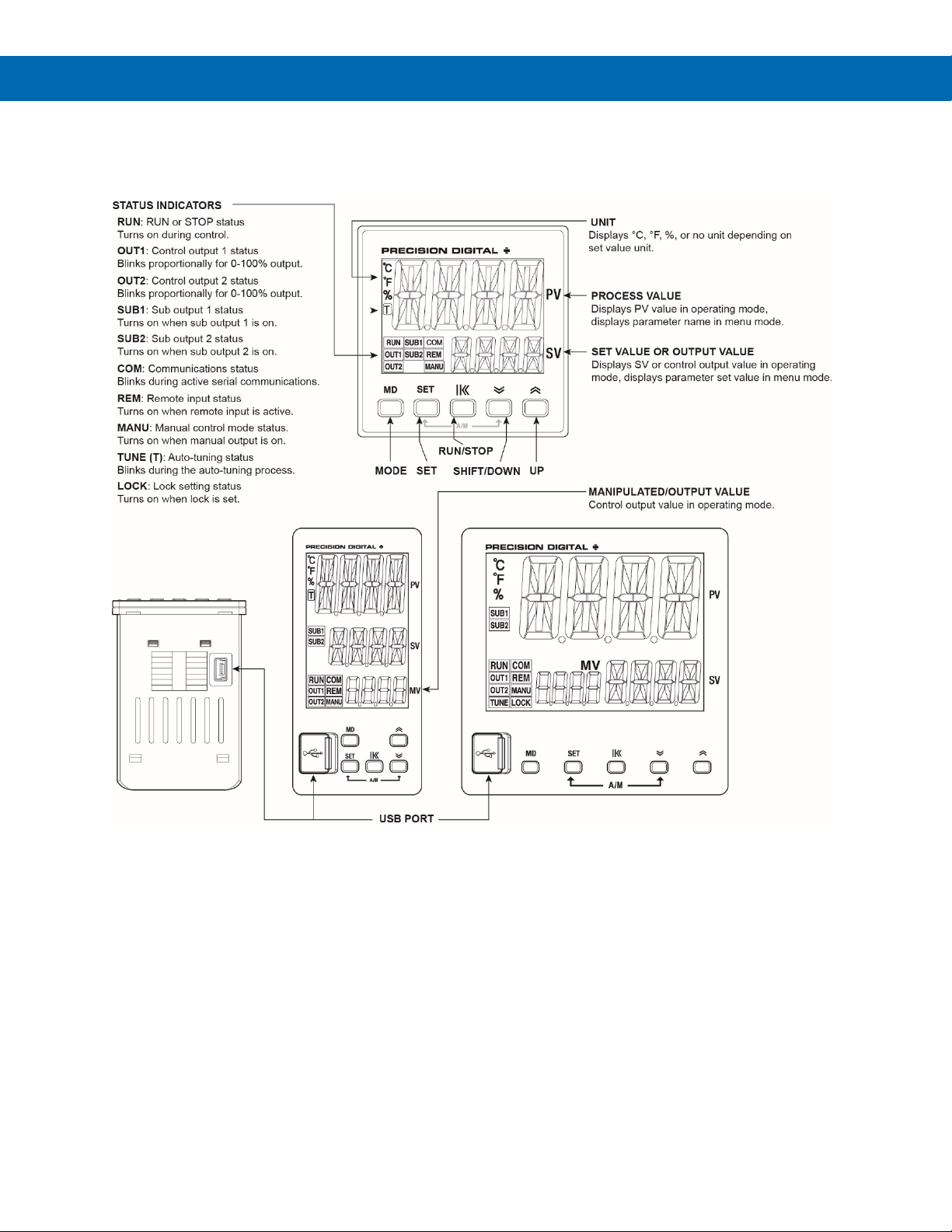
Figure 22. Front Panel Buttons and Indicators
Front Panel Buttons and Status Indicators
Instruction Manual
22
Page 23
SuperNova PD500 PID Process & Temperature Controllers
There is no need to recalibrate the controller
Group
Display
Group
Name
General Description
G.SV
Set
Group
Select active Set Values and
G.IN
Input
Group
Configure input type and
display scaling.
G.OUT
Output
Group
Configure control outputs.
G.SET
Set
Group
Activate digital inputs and
view system information.
G.COM
Comm
Group
Configure Modbus RS-485
parameters.
G.SUB
Sub
Group
Assign alarm relays, set
delays and relay operation.
G.TRS
Transmit
Group
Configure retransmit output
and remote SV input.
G.ALM
Alarm
Group
Configure alarm types and
related parameters.
G.CTL
Control
Group
Configure for auto-tuning,
PID zones, and SV ramps.
Setup and Programming
Instruction Manual
when first received from the factory.
The controller is factory calibrated for all
input types prior to shipment on calibration
equipment that is certified to NIST standards.
Overview
There are no jumpers to set for the controller input
selection.
Setup and programming are done using SuperNova
software or through the front panel buttons.
After power and input signal connections have been
completed and verified, apply power to the controller.
Setting Up the Controller
The Programming Menu is organized into various
Groups. These Groups contain individual parameters
to configure the functions of the controller.
It is recommended to begin programming by
configuring the Input Group (G.IN). Changing
certain input parameters will reset most other
setup parameters.
Configure the Input Group first. It is then
recommended that you proceed to the Output Group,
Setup Group, and continue in order, ending with the
Set Value Group to enter a control set point. Finally,
for most applications, initial auto-tuning in the Control
Group.
Value
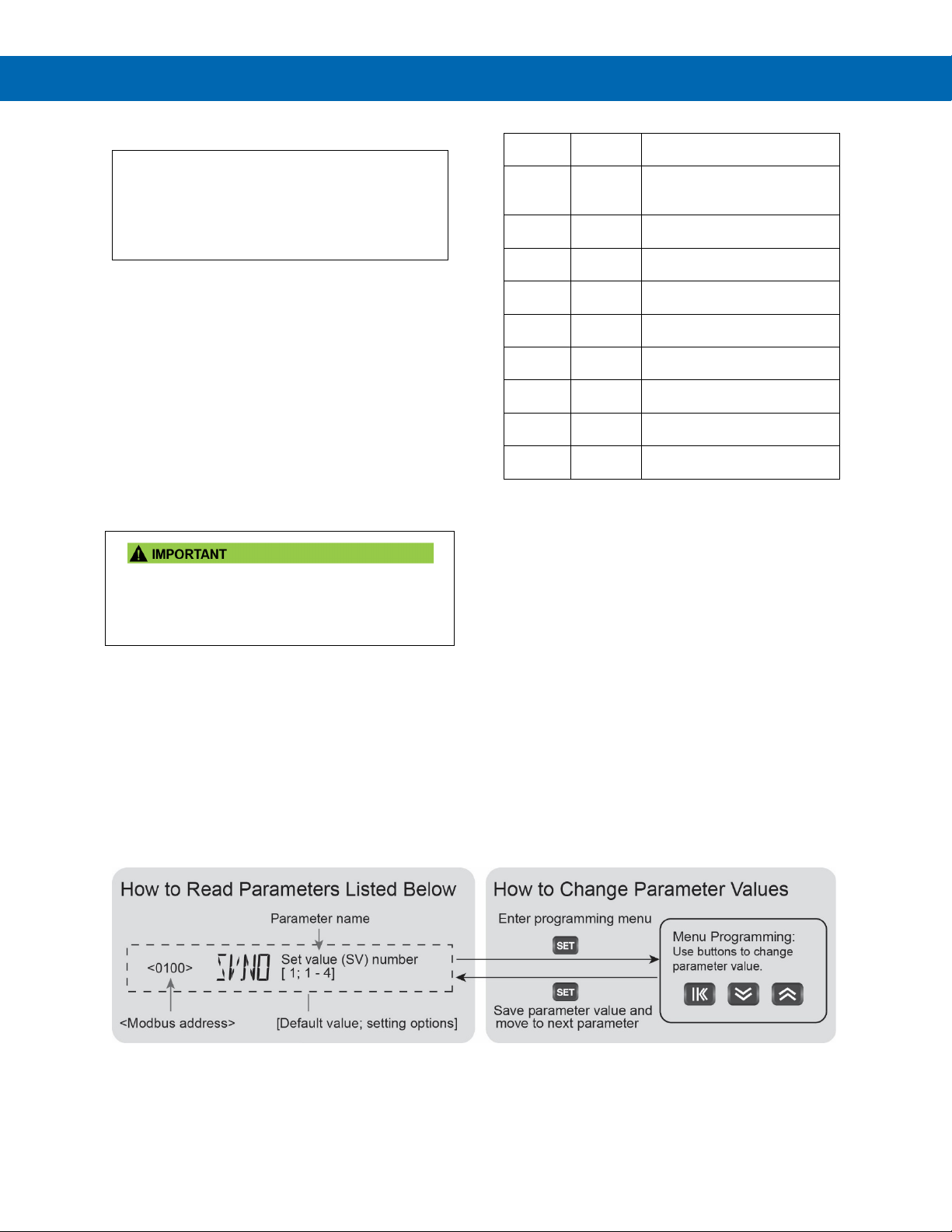
• Press and hold the Mode button (MD) for one
second to enter Programming Mode then press
the Down (or Up) arrow button to scroll through
the programing groups.
• Hold Mode (MD) at any time to exit and return to
Run Mode. Changes made to settings prior to
pressing Enter are not saved.
• To enter a Group or change a parameter, press
SET.
• Press the Down (or Up) arrow key to scroll
through individual parameters within a Group.
• Press the Mode (MD) key when navigating
parameters to return to the group menu.
• Changes to the settings are saved to memory
only after pressing SET.
• The display moves to the next menu every time a
setting is accepted by pressing SET.
Set Value limits.
23
Page 24
SuperNova PD500 PID Process & Temperature Controllers
Default
Value
SV.NO
1 - 4 - 1
FR-L to FR-H (Note 2)
SV-L < SV-H
FR.H (Note 2)
SL.H (Note 3)
FR.L (Note 2)
SL.L (Note 3)
SV-1
SV-2
SV-3
SV-4
Programming the Controller
The following section defines the parameters in each
of the setup Group menus.
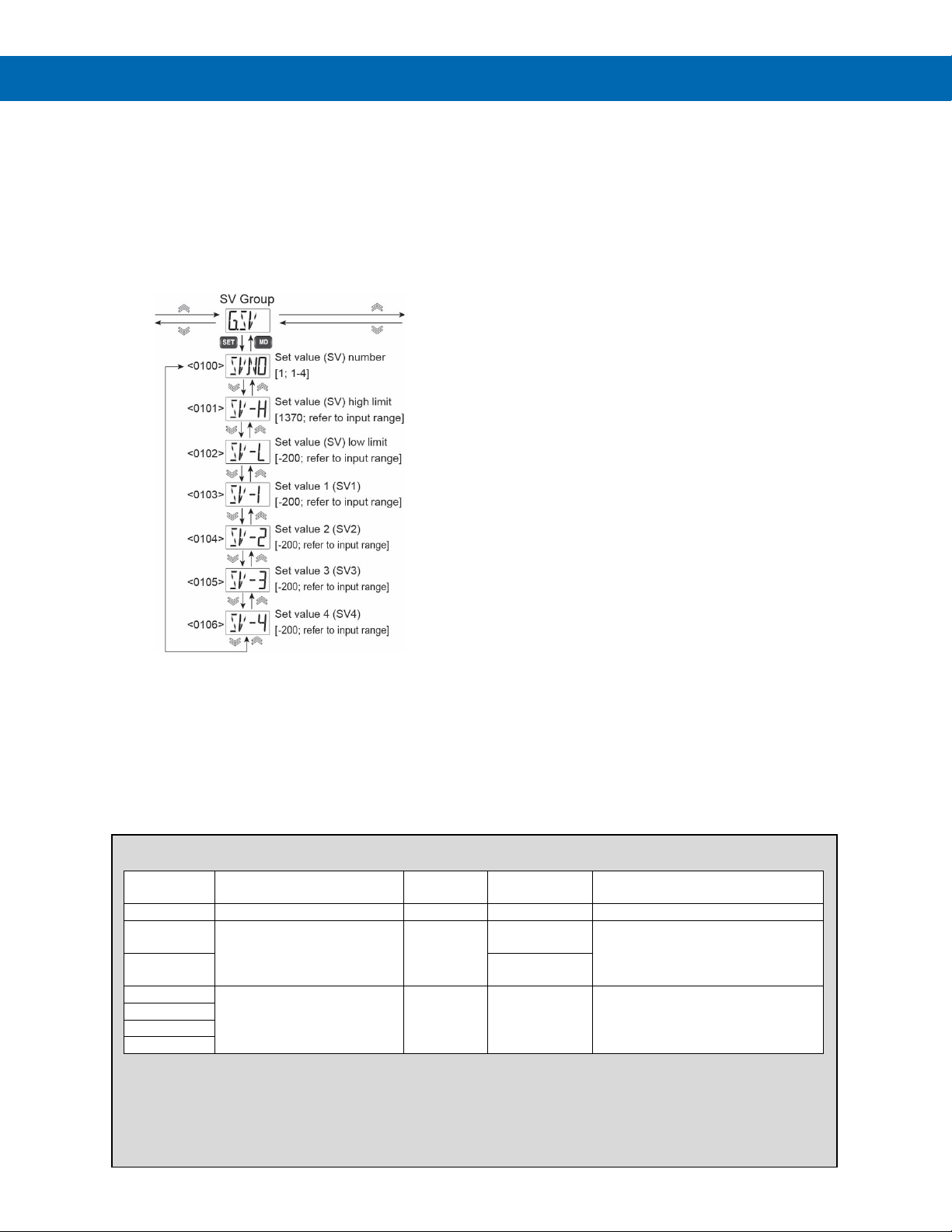
Set Value Group (G.SV)
The Set Value (SV) Group contains parameters used
to program a new Set Value, set limits on the Set
Value, or select from existing Set Values.
Set Value and Set Value Number (SV. NO)
The active Set Value is the set point the controller will
attempt to maintain. There are four programmable Set
Values (SV1 to SV4).
The Set Value Number (SV.NO) parameter selects
which programable Set Value number, 1 to 4, is
active.
In addition to setting this parameter directly, digital
inputs may be used to select from SV1 and SV4 or
the remote Set Value input (REM).
The use of digital inputs and the remote SV input will
change the behavior of this parameter and selecting
which Set Value is used.
• When the digital inputs are enabled the
digital input selection will take precedence
over the Set Value Number selected.
• When the remote SV input (REM.E) is ON,
the set value number and programmed set
points will be ignored.
• When both the digital inputs are enabled,
and the remote SV input is enabled, using
the digital inputs to select SV-4 will use the
REM input to select the Set Value.
SV-1 to SV-4 must be within the limits set by the SV
High Limit (SV-H) and SV Low Limit (SV-L)
parameters.
Set Value High Limit (SV-H) and Set Value Low Limit (SV-L)
These may be used to prevent the setting of
unintentional Set Values. Both the selections of
SV.NO, as well as the REM SV are limited by these
parameters.
The Set Value High Limit (SV-H) will define the high
limit of the Set Value.
The Set Value Low Limit (SV-L) will define the low
limit of the Set Value.
Set Value 1, 2, 3, and 4 (SV-1, SV-2, SV-3, SV-4)
SV-1, 2, 3, and 4 are the Set Values the controller will
try to maintain. Only one Set Value may be used at a
time by the controller.
Instruction Manual
Parameter Setting Range Unit
SV-H
SV-L
1. Default value determined by the default unit of the selected input type.
2. The high and low SV limits are the high and low limit for the selected input type. FR.H/L is used when
thermocouple or RTD inputs are selected.
3. The high and low SV limits are the high and low limit for the selected input type. SL.H/L is used when mA,
VDC, or mVDC inputs are selected.
G.SV Parameter Details
SL-L to SL-H (Note 3)
Also,
SV-L to SV-H Note 1 SV-L
Parameter Display Condition
Note 1
24
Page 25
SuperNova PD500 PID Process & Temperature Controllers
Input Type
Display
Range
K
K0
-328 to 2498°F
-200 to 1370°C
K1
-148 to 932°F
-100.0 to 500.0°C
-200 to 1200°C
J1
-328 to 1652°F
-199.9 To 900.0°C
E
E1
-328 to 1652°F
-199.9 to 900.0°C
T
T1
-328 to 752°F
-199.9 to 400.0°C
R
R0
32 to 3092°F
0 to 1700°C
100 to 1800°C
S
S0
32 to 3092°F
0 to 1700°C
L
L1
-328 to 1652°F
-199.9 to 900.0°C
N
N0
-328 to 2372°F
-200 to 1300°C
U
U1
-328 to 752°F
-199.9 to 400.0°C
W
W0
32 to 4172°F
0 to 2300°C
PLII
PL0
32 to 2372°F
0 to 1300°C
JPt100
JPt0
-328 to 932°F
-200 to 500°C
JPt1
-328 to 932°F
-199.9 to 500.0°C
Pt100
Pt0
-328 to 1184°F
-200 to 640°C
-199.9 to 640.0°C
4-20 mA
1-5V*
1-5 VDC
1-5V
0-5 VDC
5V
0-10 VDC
10V
0-50 mVDC
0.05V
0-100 mVDC
0.1V
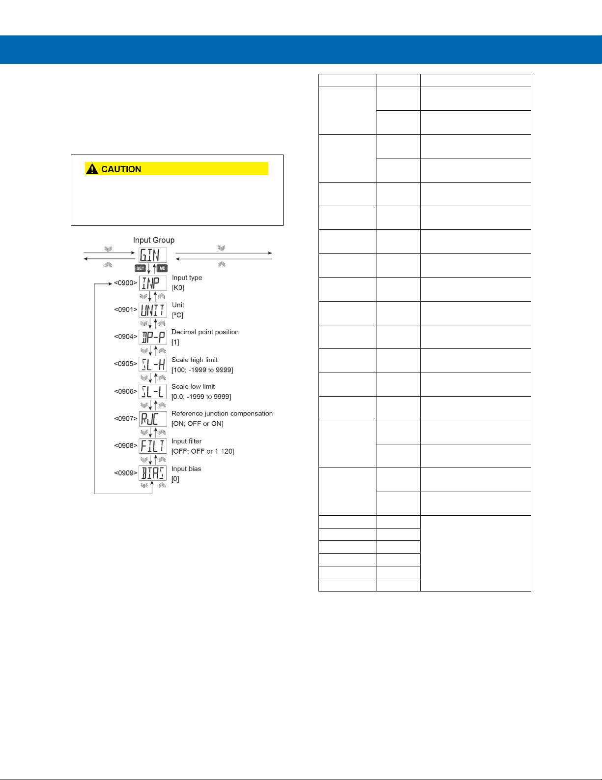
Input Group (G.IN)
The Input Group includes parameters to select the
input type, define display units, and scale a process
input.
It also contains parameters related to the temperature
reference junction, input filtering, and making input
calibration adjustments.
It is recommended to begin programming by
configuring the Input Group (G.IN).
Changing certain input parameters will reset
most other setup parameters.
J J0 -328 to 2192°F
B B0 212 to 3272°F
Instruction Manual
Input Type (INP)
The Input Type (INP) parameter is for selecting the
input type. Refer to Figure 23. Input Type and Range
Selection to find the parameter setting display
selection for the desired input type.
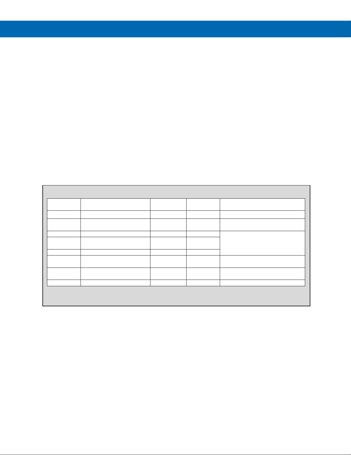
Unit (UNIT)
UNIT can be set to °C and °F when a thermocouple or
RTD input is selected. The calculation to display each
unit type is done automatically.
For mA, VDC, or mVDC inputs, the units may be set
to °C and °F, %, or no unit (NONE). The selected unit
is displayed, but scaling must be done to properly
read the selected unit.
Decimal Point Position (DP-P)
This parameter sets the number of decimal places to
be used for mA, VDC, and mVDC inputs. It is used for
the display values as well as the scaling parameters
SL-L and SL-H.
Pt1 -328 to 1184°F
-1999 to 9999
*Connect a 250 Ω resistor across the input terminals.
Figure 23. Input Type and Range Selection
25
Page 26
SuperNova PD500 PID Process & Temperature Controllers
Default
Value
INP
K0 through 0.1 VDC
-
K0
°C, °F (Note 2)
°C, °F, %, no unit (Note 3)
DP-P
0 – 3 - 1
-1999 - 9999
(however, SL-L < SL-H)
SL-L Note 1
0.0
Input selected is a thermocouple
input type
Time
(seconds)
BIAS
EUS (-100.0-100.0)%
Note 1
EUS 0.0%
3. Selections when mA, VDC, or MVDC input type selected.
Scale High Limit (SL-H)
Set the display value for the desired units when at the
high limit of the selected mA, VDC, or mVDC input
type. Refer to Figure 23. Input Type and Range
Selection to see the default high limit of an input type.
Scale Low Limit (SL-L)
Set the display value for the desired units when at the
low limit of the selected mA, VDC, or mVDC input
type. Refer to Figure 23. Input Type and Range
Selection to see the default high limit of an input type.
Cold Junction Compensation (RJC)
Reference junction compensation, or cold junction
compensation, is used if a thermocouple input type is
selected. It is used to maintain an accurate reading of
the thermocouple input. This may be turned off for
specific applications where this is necessary.
Filter Time (FILT)
The input noise filter is used to compensate for noise
of unsteady readings of the input. Noise may impact
the PV reading and will also results in sudden
changes to the output. Increasing the Filter time will
help eliminate the effects of this noise.
However, greatly increasing the filter time will result in
a longer delay before changes to the input signal are
reflected in the display and control outputs.
Bias Offset for Calibration (BIAS)
This parameter is present when a thermocouple or
RTD input type is selected. It allows for an offset to be
programmed into the display value. This can be used
to adjust the input display value.
G.IN Parameter Details
Instruction Manual
Parameter Setting Range Unit
UNIT
SL-H
RJC OFF, ON - ON
FILT OFF, 1 - 120
1. Default value determined by the default unit of the selected input type.
2. Selections when thermocouple or RTD input type selected.
- °C
Note 1 100.0
OFF
Parameter Display Condition
Input selected is mA, VDC, or
mVDC input type
26
Page 27
SuperNova PD500 PID Process & Temperature Controllers
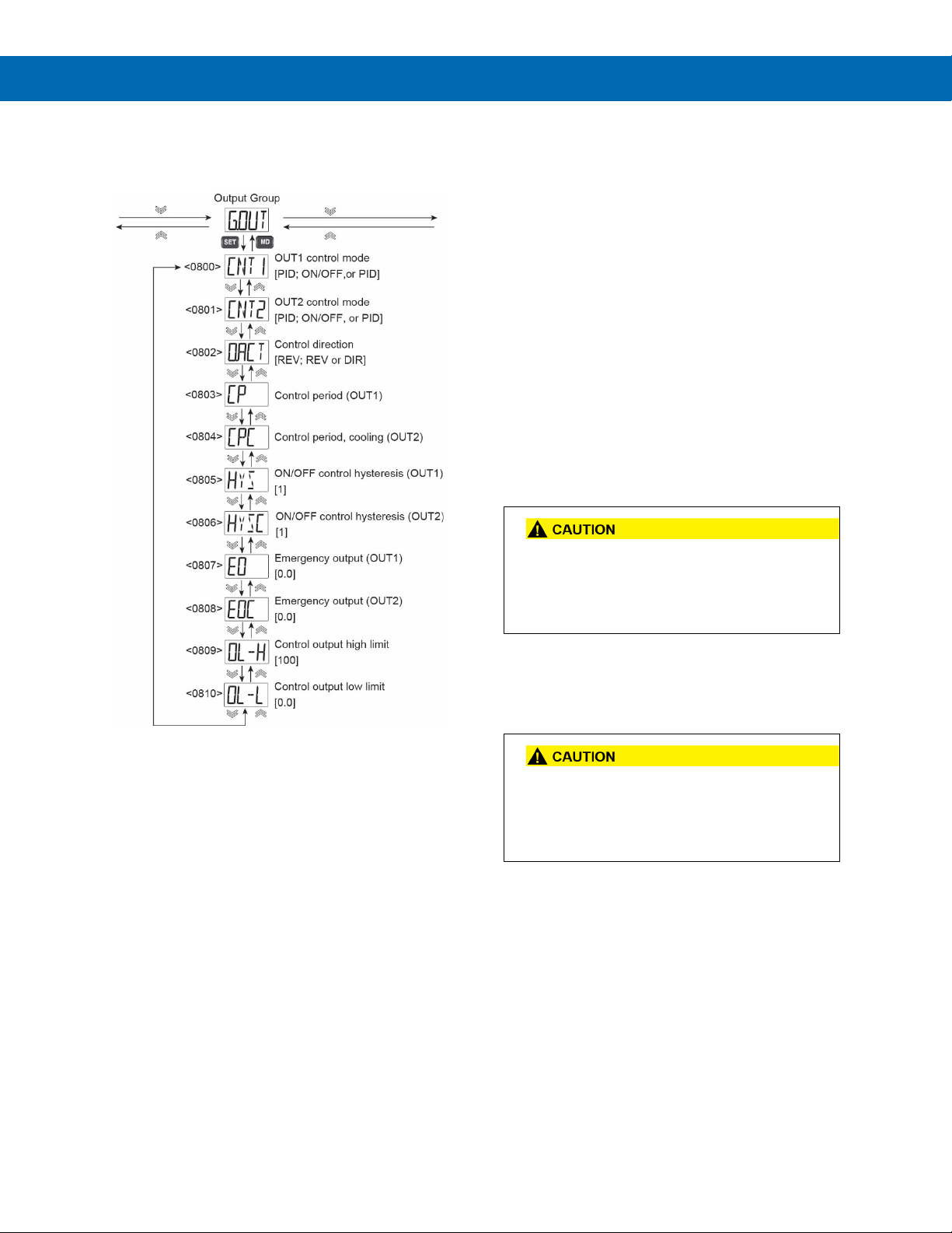
Output Group (G.OUT)
The Output Group includes parameters used to
configure the general operation of the control outputs.
Heating & Cooling Control Mode
When OUT2 is set to either ONOF or PID, the
controller will automatically enter heating and cooling
control mode.
In heating and cooling control mode, the Output
Action O.ACT parameter is disabled. OUT1 is always
the heating side control output, and OUT2 is always
the cooling side control output.
Disable Heating & Cooling Control
To disable Heating & Cooling control mode, set OUT2
Control Mode (CNT2) to NONE. When this is done,
the Output Action (O.ACT) parameter is used to
selecting heating (reverse) or cooling (direct) control
for OUT1.
Control Period, Heating (CP)
This parameter is used to set the on/off cycle time of
OUT1 when in OUT1 Control Mode (CNT1) is set to
On/Off (ONOF) control mode. This parameter is only
used when OUT1 is a relay or SRR output.
Instruction Manual
OUT1 Control Mode (CNT1)
The control output mode of OUT1 can be selected
from On/Off (ONOF) or PID.
OUT2 Control Mode (CNT2)
The control output mode of OUT2 can be selected
from NONE, On/Off (ONOF) or PID.
Output Action (O.ACT)
The operation in which the control amount increases
when the deviation (PV - SV) is positive is referred to
as a direct action, and the operation in which the
control amount increases when the deviation is
negative is referred to as a reverse action.
You can select direct or reverse action only when
OUT2 Control Mode (CNT2) is set to NONE
When using a mechanical relay for control, set
the control period to at least 20 seconds.
When using SSR output for control, set the
control period to at least 1 second.
Control Period, Cooling (CPC)
This parameter is used to set the on/off cycle time of
the OUT2 relay when in OUT2 Control Mode (CNT2)
is set to On/Off (ONOF) control mode.
When using a mechanical relay for control, set
the control period to at least 20 seconds.
When using SSR output for control, set the
control period to at least 1 second.
27
Page 28
SuperNova PD500 PID Process & Temperature Controllers
Control Output 2 (CNT2) is NONE.
CNT1
EO or EOC
Range
OUT1 or OUT
2 Output in
Emergency/
Error State
If OL-L > EO,
(MV = 0.0%)
If OL-H < EO,
MV = OLH
If OL-L ≤ EO ≤ OL-H,
MV = EO
HOUT Emergency Output when Control Output 1
(CNT1) and Control Output 2 (CNT2) in Use
CNT1
On/Off (ONOF)
PID EO
EO = 0.0% or
100.0%
0.0 ≤ EO ≤ 100.0
HOUT
If OLH < 100.0,
HOUT = 0.0
If OL-H < EO,
HOUT = OL-H
HOUT = EO
If 0 ≤ EO ≤ OL-H,
HOUT = EO
COUT Emergency Output when Control Output 1
(CNT1) and Control Output 2 (CNT2) in Use
CNT2
On/Off (ONOF)
EOC
EOC = 0.0% or
100.0%
0.0% ≤ EOC ≤
100.0%
COUT
If OLH < 100.0%,
COUT = 0.0%
If OL-H < EOC,
COUT = OL-H
COUT = EO
If 0 ≤ EOC ≤ OL-H,
COUT = EOC
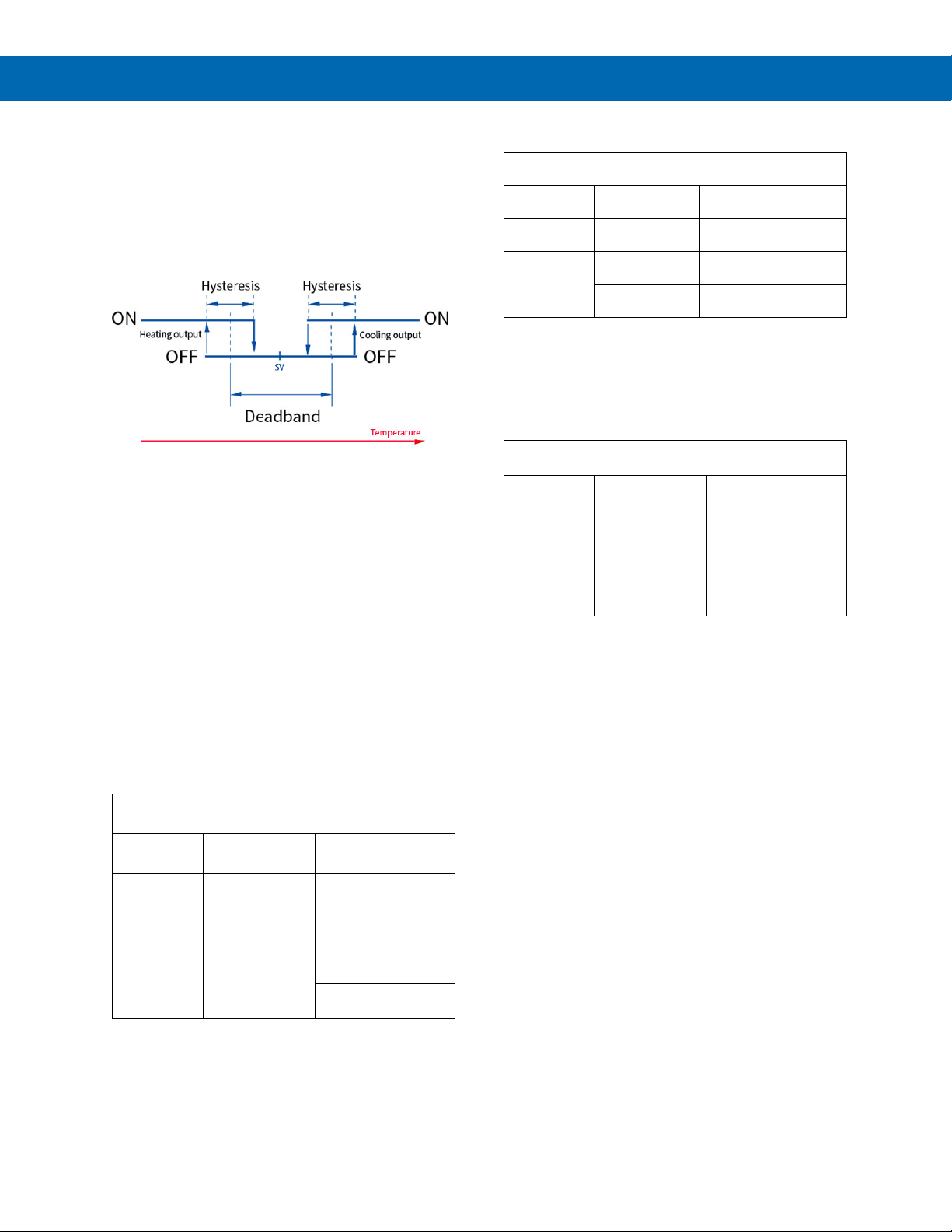
Hysteresis, Heating (HYS) and Hysteresis, Cooling (HYSC)
When using on/off control, the hysteresis sets the
difference from the on state and the off state of the
heating or heating & cooling outputs.
The output deadband of the heating side and cooling
sides can be set individually.
The deadband during heating & cooling on/off control
is as follows.
Figure 24. Heating & Cooling Hysteresis
Hysteresis (HYS) and Cooling Hysteresis (HYSC) are
displayed only when Out1 Control Mode (CNT1) and
OUT2 Control Mode (CNT2) are programmed for
On/Off (ONOF) control respectively.
Emergency Output, Heating (EO) and Emergency Output Cooling (EOC)
This parameter sets the output levels in the case of
internal PV calculation error or an input sensor burn
out error.
The output conditions of EO and EOC according to
the conditions are as follows.
When using only CNT1 (CNT2 as NONE or models
without OUT2 option), emergency output EO is
generated as shown below according to On/Off and
PID settings.
Emergency Output when
Mode On/Off (ONOF) PID
EO = 0.0%
or EO = 100.0%
MV = EO
0.0 ≤ EO ≤ 100.0%
When both CNT1 and CNT2 are used, EO and EOC
are generated as follows.
Mode
Range
Output
Note that when using on/off control, if parameter
Output Limit High (OL-H) is set to less than 100%, the
emergency condition output will remain 0%,
regardless of the setting for Emergency Output,
Heating (EO).
Mode
Range
Output
Note that when using on/off control, if parameter
Output Limit Low (OL-L) is set to less than 100%, the
emergency condition cooling output will remain 0%,
regardless of the setting for Emergency Output,
Cooling (EOC).
Output Limit High (OL-H) and Low (OL-L)
The output limits high and low restrict the control
output (MV) percent output to greater than the
minimum and less than the maximum output levels.
For models where parameter OUT2 Control Mode
(CNT2) is set to NONE, Output Limit High (OL-H) is
the output high limit and Output Limit Low (OL-L) is
the output low limit. The minimum output is 0%, and
the maximum output is 100%.
If OUT2 Control Mode (CNT2) is not NONE, the OL-H
parameter is the heating output high limit, and the
OL-L is the cooling output high limit.
Instruction Manual
PID
28
Page 29
SuperNova PD500 PID Process & Temperature Controllers
Default
Value
CNT1
ONOF, PID
PID
CNT2
NONE, ONOF, PID
NONE
OUT2 control mode CNT2 is set
to NONE
OUT1 option is RLY or SSR and
to PID.
Time
(seconds)
OUT2 control mode CNT2 is set
to PID.
OUT1 control mode CNT1 is set
to ONOF.
OUT2 control mode CNT2 is set
to ONOF.
(-5.0 - 105.0) % (Note 2)
(0.0 - 105.0) % (Note 3)
OUT2 control mode CNT2 is set
to ONOF or PID.
(-5.0 - 105.0) % (Note 2)
(However, OL-L < OL-H)
(-5.0~105.0) % (Note 2)
(However, OL-L < OL-H)
3. Selections when mA, VDC, or MVDC input type selected.
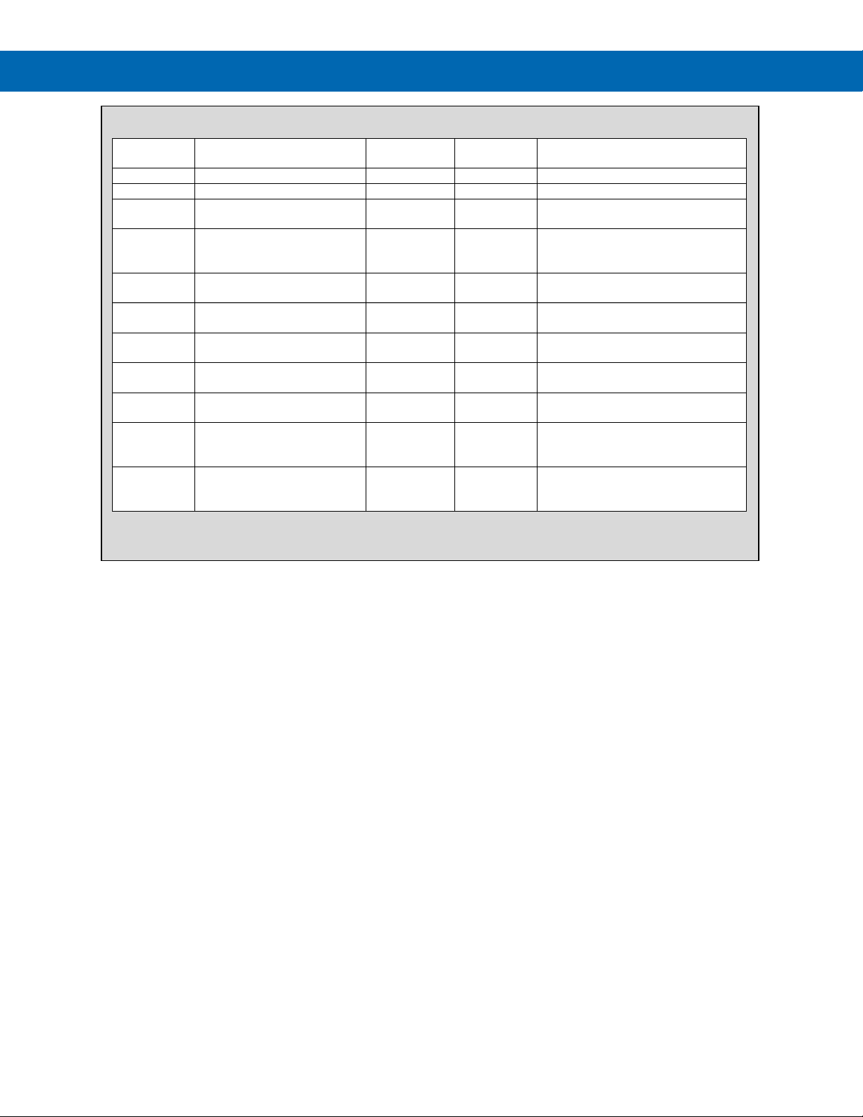
G.OUT Parameter Details
Instruction Manual
Parameter Setting Range Unit
O.ACT REV, DIR REV
CP 1 - 1000 s
CPC 1 - 1000 s
HYS EUS (0.0 - 100.0) % Note 1 1
HYSC EUS (0.0 - 100.0) % Note 1 1
EO
EOC (0.0~105.0) % % 0.0
OL-H
OL-L
1. Set by G.IN parameter UNIT.
2. Selections when thermocouple or RTD input type selected.
(0.0 - 105.0) % (Note 3)
(0.0~105.0) % (Note 3)
Time
(seconds)
% 0.0
%
%
RLY : 20
SSR : 2
20
100.0
0.0
Parameter Display Condition
OUT1 control mode CNT1 is set
OUT1 control mode CNT1 is set
to PID.
OUT1 control mode CNT1 or
OUT2 control mode is set to PID.
29
Page 30
SuperNova PD500 PID Process & Temperature Controllers
Function
DI 1
DI 2
R/S
STOP
0 - RUN 1 -
SV
SV1 - 0
SV4 or REM
- 1
It is recommended to save your settings using
Settings Group (G.SET)
The Settings Group includes parameters for general
controller setup, such as power-on operation,
resetting to factory default settings, or locking
parameters to prevent accidental changes. It also
contains information on the controller build and
firmware version.
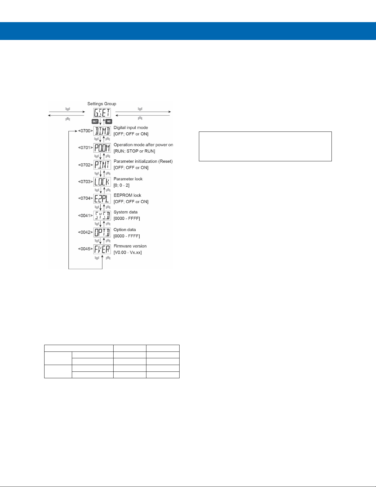
Digital Input Mode (DI.MD)
The digital inputs may be enabled (ON) or disabled
(OFF).
If enabled, the digital inputs will function per the table
below, with digital input 1 (DI1) controlling run/stop
mode, and digital input 2 (DI2) determining the use of
set value 1 (SV1) or set value 4 (SV4).
In a controller with the remote set value input option,
DI2 will determine the use of SV1 or the remote set
value input to set the set value.
Power-On Operation Mode (POOM)
The controller can be programmed to enter RUN or
STOP mode when it powers on.
Set PO.OM to RUN to be in RUN or control mode
when powered on, and PO.OM to STOP to be in
STOP or monitoring mode when powered on.
Parameter Initialization (P.INT)
This parameter restores all other parameter settings
in the controller to the factory default settings.
the SuperNova Programming Software before
resetting all parameters to factory default.
To reset to factory defaults, set this parameter to ON.
Once this is done, a Y/N confirmation request will be
displayed. Select YES to reset the unit to factory
defaults, and NO to cancel the reset request.
Parameter Lock (LOCK)
Use of the parameter lock prevents accidental
changes to settings in the controller.
The Lock parameter may be set to the following
levels.
If LOCK is set to 0, the parameter lock is off.
If LOCK is set to 1, all parameters except LOCK and
all parameters in the G.SV group are locked.
If LOCK is 2, all parameters except LOCK are locked.
The parameter lock may be set by holding the SHIFT
and SET keys for three seconds. When this is done,
LOCK setting 2 is enabled.
Locked parameter groups are read-only accessible by
serial communications, and the settings in them
cannot be changed via the programming software or
Modbus communications.
If you press the SET button to change a parameter
has been locked, LOCK will blink. Press the DOWN,
UP or MD keys to move to navigate to the next
parameter or group.
Instruction Manual
30
Page 31
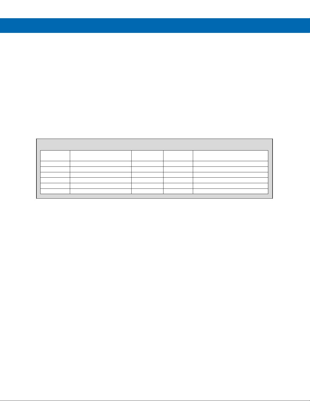
SuperNova PD500 PID Process & Temperature Controllers
Default
Value
DI.MD
OFF, ON
-
OFF
Models with digital inputs only
PO.OM
STOP, RUN
-
STOP
P.INT
OFF, ON
-
OFF
Y/N
NO, YES
-
NO
Only for parameter initialization
LOCK
0, 1, 2 - 0
E2P.L
OFF, ON
-
OFF
EEPROM Lock (E2P.L)
The programmed settings of the controller are stored
in two types of hardware memory, short-term use
RAM and long-term and secure EEPROM.
Very rarely, it is necessary for an application to write
new settings by serial communications so often to the
controller that it risks reaching the maximum number
or read/write operations of EEPROM hardware.
To prevent this, when the EEPROM Lock is ON, all
data written by serial communications will be stored in
RAM only and will not be stored in EEPROM. Only
the Parameter Lock (LOCK) and the EEPROM Lock
(E2P.L) will be stored in EEPROM.
As a result of turning on the EEPROM Lock, when a
power cycle occurs on the controller, all settings and
data received by serial communications will be lost.
System Data (SYS.D)
This parameter displays system data useful to the
factory for troubleshooting.
Option Data (OPT.D)
This parameter displays build option data useful to the
factory for troubleshooting.
Firmware Version (F.VER)
This parameter displays the firmware version installed
on the controller.
G.SET Parameter Details
Instruction Manual
Parameter Setting Range Unit
Parameter Display Condition
31
Page 32
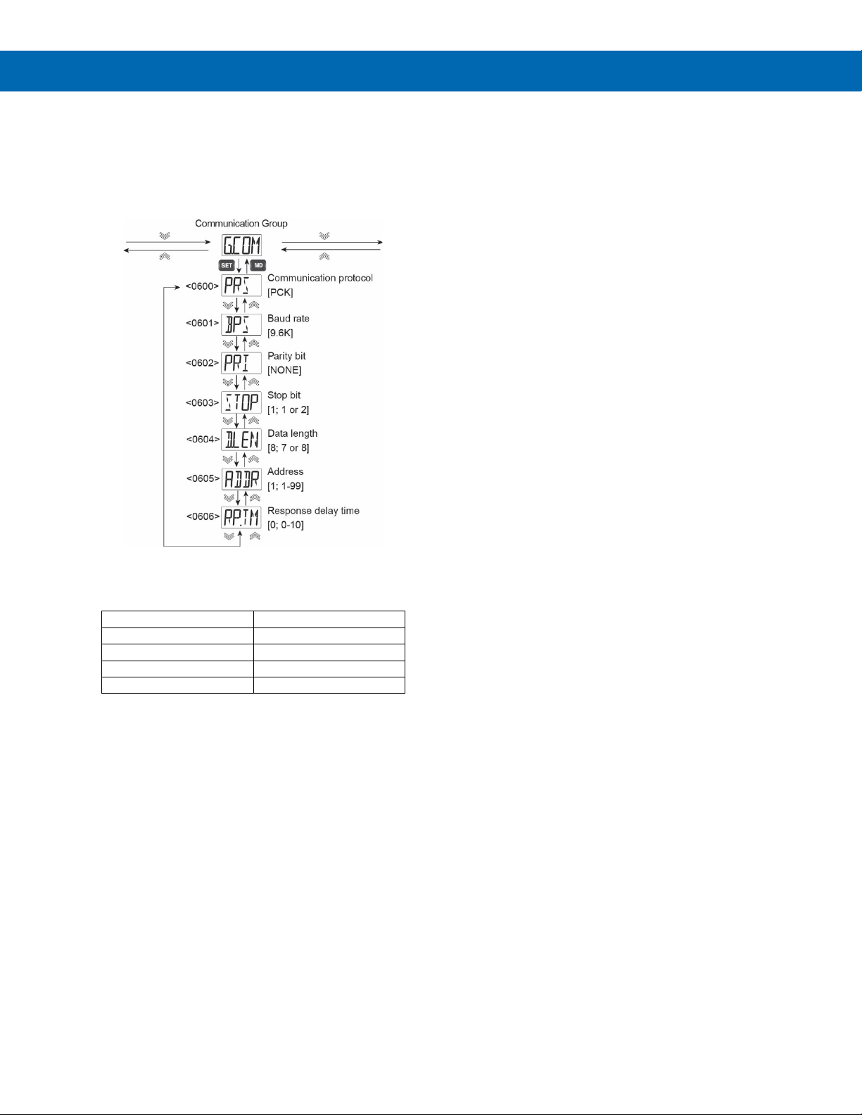
SuperNova PD500 PID Process & Temperature Controllers
Protocol
Menu Selection
PC Link without Checksum
PCK
PC Link with Checksum
PCKS
Modbus ASCII
ASCI
Modbus RTU
RTU
Communication Group (G.COM)
The Communication Group includes parameters for
configuring RS-485 serial communications. The
controller supports PC Link and Modbus protocols,
with 2-wire half-duplex configuration per the EIA
RS-485 standard.
Protocol Select (PRS)
Select the protocol for serial communications. There
are four protocols supported.
Parity Bit (PRI)
Select if parity bit function as none (NONE), even
(EVEN), or odd (ODD) parity.
Stop Bit (STOP)
Select 1 or 2 stop bits.
Data Length (D.LEN)
Select the data length to be 7 or 8 bits.
Address (ADDR)
The controller communication address can be set as
address 1 to 99. Up to 31 devices can be connected
on the RS-485 bus, each requiring a unique
communication address.
Response Time delay (R P. T M )
The response time delay parameter increases the
response time during communications. The response
time is the time from the handling of the received data
to the start of transmission and is calculated as
follows:
Response Time = (Received Data Handling Time) +
(Response Time delay Setting X 50 milliseconds)
Instruction Manual
PC Link without Checksum does not have a
checksum, it cannot verify data integrity if data is
distorted due to communication line noise or other
problems. However, PC Link with Checksum and
Modbus ASCII or RTU can verify data integrity with a
checksum, so it can be used more reliably. Therefore,
we recommend not to use PC Link without Checksum
if avoidable.
Bits per Second (BPS)
Set the communication speed in bits per second
(BPS). Select from the following 6 communication
speeds: 4,800 (4.8k), 9,600 (9.6k), 14,400 (14.4k),
19,200 (19.2k), 38,400 (38.4k), or 57,600 (57.6k) bps
32
Page 33
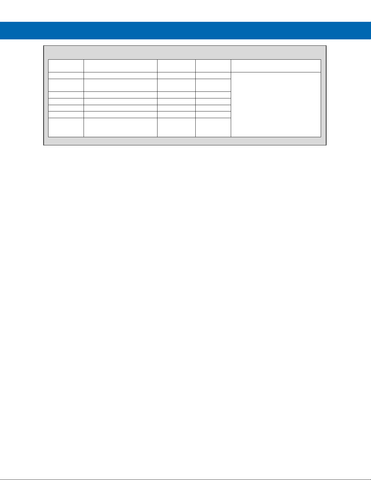
SuperNova PD500 PID Process & Temperature Controllers
Default
Value
PRS
PCK, PCKS, ASCI, RTU
PCK
BPS
4.8K, 9.6K, 14.4K, 19.2K,
38.4K, 57.6K
BPS
9.6K
PRI
NONE, EVEN, ODD
bit
NONE
STOP
1 or 2
bit
1
D.LEN
7 or 8
bit
8
ADDR
1 - 99 1
RP.TM
0 - 10
Number of
increments
0
G.COM Parameter Details
Instruction Manual
Parameter Setting Range Unit
Parameter Display Condition
Only on models with RS-485
option
50 ms time
33
Page 34
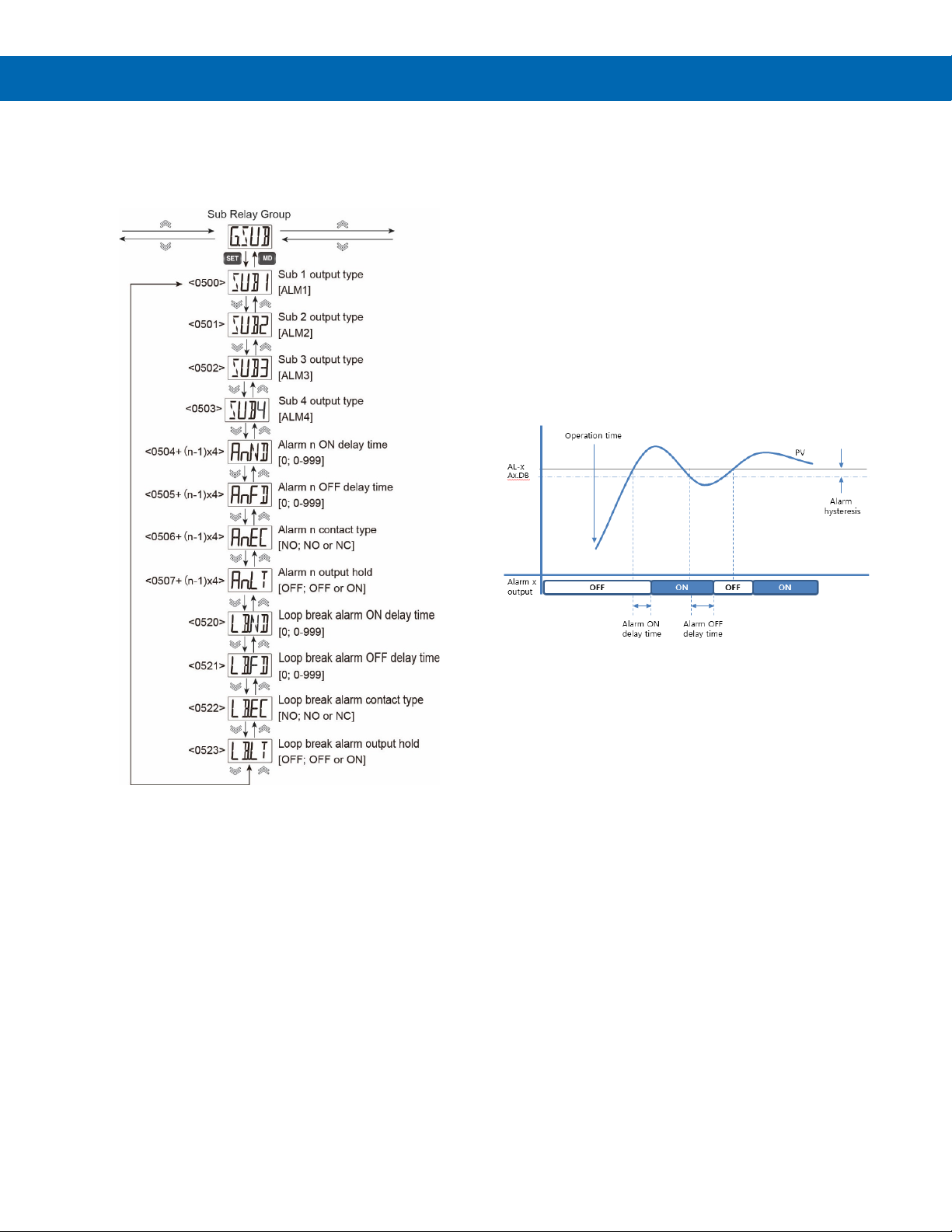
SuperNova PD500 PID Process & Temperature Controllers
Sub Relay Group (G.SUB)
The Sub Relay Group is used to assign alarms to the
Sub relays and set relay controls such as on and off
delays, fail-safe mode, and latching functions.
Alarm ON Time Delay (An.ND)
When an alarm condition occurs, the alarm will turn
on only after the ON time delay. Set the ON time
delay in seconds. If the ON time delay is set to zero,
the alarm turns on immediately.
Alarm OFF Time Delay (An.FD)
When the alarm condition is cleared, the alarm will
turn OFF only after the OFF time delay. Set the OFF
time delay in seconds. If the OFF time delay is set to
zero, the alarm turns OFF immediately.
While the alarm OFF time delay is set, the latch
release function will not operate immediately upon the
alarm condition being cleared. The latching alarm
may only be reset after the alarm OFF time delay has
elapsed.
Instruction Manual
Sub Output Number & Type (SUBn)
The Sub relay outputs can be used for general alarms
or loop break alarms.
To set a Sub relay output to be a specific alarm,
configure the alarm in the Alarm Group and select the
desired alarm as the alarm Type.
For example, to have Sub relay 1 trigger based on the
programming for Alarm 3, select ALM3 as the setting
for parameter SUB1.
Because only two Sub relay outputs exist on the
PD510, the OUT2 relay of the PD510 may be
configured to operate as an alarm output.
To setup the OUT2 relay of the PD510 as an alarm
output:
1. Set the G.OUT group parameter CNT2 to
NONE.
2. Set the G.SUB group parameter SUB3 to
ALM3.
3. Set the parameters related to alarm 3 in the
G.ALM group.
Figure 25. Alarm Operation when ON & OFF Time
delays are Set
Alarm Fail-Safe (An.EC)
The sub output relays are type A electromechanical
relays. Each has a NO: Normally Open contact.
However, it may be made to function as a Normally
Closed contact with the Alarm Fail-Safe parameter.
If NO is selected, the relay functions normally, and
energizes in the alarm condition.
If NC is selected, the relay is energized in normal
conditions, and de-energizes in alarm conditions. This
also means that in the case of a power failure, the
relay contact will be de-energized, similar to when in
alarm condition.
34
Page 35

SuperNova PD500 PID Process & Temperature Controllers
Alarm Latch (An.LT)
The latch function is used to hold the alarm output
state even after the alarm condition has been cleared
(including the deadband).
When An.LT is set to ON, the Alarm Group (G.ALM)
parameter An.LR becomes accessible, where n can
be any of alarms 1, 2, 3, or 4. The An.LR parameter is
set to RST when there is no alarm and becomes SET
when an alarm condition occurs.
To release the alarm condition, the Alarm Group
(G.ALM) parameter Ax.LR must be set to RST while
the alarm condition is cleared. As a shortcut, the
operator may press the DOWN or UP arrow keys to
reset a latched alarm after the alarm condition has
cleared (including the deadband).
Loop Break Alarm ON Time delay (LB.ND)
When a loop break alarm condition occurs, the alarm
will turn on only after the ON time delay. Set the ON
time delay in seconds. If the ON time delay is set to
zero, the alarm turns on immediately.
Loop Break Alarm OFF Time delay (LB.FD)
If a loop break alarm (LBA) is generated and the
control output is not 0% or 100%, or the PV enters the
Loop Break Deadband (LB.DB) range, the LBA is
released. At this time, if LB.FD is set to a value other
than zero, it will be released after that many seconds
elapse.
Loop Break Alarm Fail-Safe (LB.EC)
The sub output relays are type A electromechanical
relays. Each has a NO: Normally Open contact.
However, it may be made to function as a Normally
Closed contact with the Loop Break Alarm Fail-Safe
parameter.
If NO is selected, the relay functions normally, and
energizes in the loop break alarm condition.
If NC is selected, the relay is energized in normal
conditions, and de-energizes in loop break alarm
conditions. This also means that in the case of a
power failure, the relay contact will be de-energized,
similar to when in loop break alarm condition.
Loop Break Alarm Latch (LB.LT)
The latch function is used to hold the alarm output
state even after the loop break alarm condition has
been cleared.
When LB.LT is set to ON, the Alarm Group (G.ALM)
parameter LB.LR becomes accessible. The LB.LR
parameter is set to RST when there is no alarm and
becomes SET when an alarm condition occurs.
To release the loop break alarm condition, the Alarm
Group (G.ALM) parameter LB.LR must be set to RST
while the alarm condition is cleared. As a shortcut, the
operator may press the DOWN or UP arrow keys to
reset a latched loop break alarm after the alarm
condition has cleared
Instruction Manual
35
Page 36
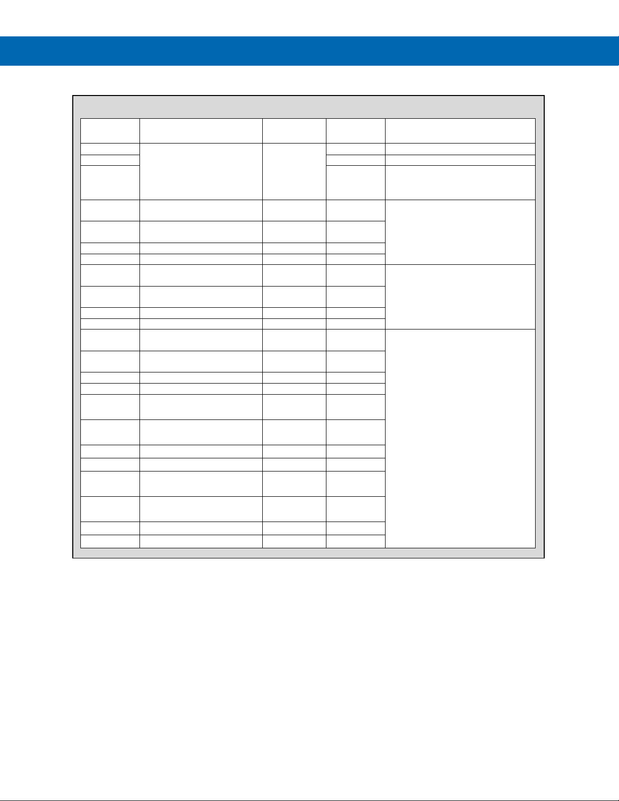
SuperNova PD500 PID Process & Temperature Controllers
Value
SUB1
NONE, ALM1, ALM2, ALM3,
ALM1
SUB2
ALM2
SUB3
ALM3
PD510: Only when the OUT2
A1.ND
0 - 999
Time
(seconds)
0
A1.FD
0 - 999
Time
(seconds)
0
A1.EC
NO, NC NO
A1.LT
OFF, ON
OFF
A2.ND
0 - 999
Time
(seconds)
0
A2.FD
0 - 999
Time
(seconds)
0
A2.EC
NO, NC NO
A2.LT
OFF, ON
OFF
A3.ND
0 - 999
Time
(seconds)
0
A3.FD
0 - 999
Time
(seconds)
0
A3.EC
NO, NC NO
A3.LT
OFF, ON
OFF
A4.ND
0 - 999
Time
0
A4.FD
0 - 999
Time
0
A4.EC
NO, NC NO
A4.LT
OFF, ON
OFF
LB.ND
0 - 999
Time
0
LB.FD
0 - 999
Time
0
LB.EC
NO, NC NO
LB.LT
OFF, ON
OFF
G.SUB Parameter Details
Parameter Setting range Unit
ALM4, LBA
Default
Instruction Manual
Parameter Display Condition
control type parameter is set to
NONE.
When a SUBx parameter to set to
ALM1.
When a SUBx parameter to set to
ALM2.
(seconds)
(seconds)
(seconds)
(seconds)
When a SUBx parameter to set to
ALM3.
36
Page 37
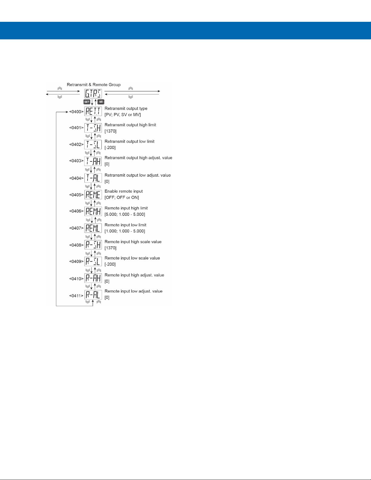
SuperNova PD500 PID Process & Temperature Controllers
Transmit & Remote Group (G.TRS)
The Transmit and Remote Group is used to configure
the 4-20 mA retransmission output as well as the
4-20 mA remote SV input.
Retransmit Adjustment High (T-AH) and Low (T-AL)
The Retransmit Adjustment High (T-AH) and
Retransmit Adjustment Low (T-AL) parameters are
used to recalibrate the 4-20 mA retransmit output.
The output may be calibrated by changing the high
and low scale PV, SV, or MV values within ±5% of the
full scale of the value.
Remote input Operation (REM)
Analog signals from 4 -20 mA (or 1-5 V) can be input
to change the set value (SV) remotely.
To accept a 4-20 mA input, connect 250 Ω resistor in
parallel to the REM input (a 0.1% high-precision
resistor is recommended) and the high and low
voltage input ranges of the remote input should be set
to 1.000 and 5.000 VDC.
Remote Input Enable (REM.E)
Units with the remote input option can turn on this
input by setting the Remote Input Enable (REM.E)
parameter to ON.
When REM.E is turned on, the value remotely input to
the REM terminals is used as the SV regardless of
the set value number selected in the SV.NO
parameter.
Instruction Manual
Retransmission Type (RET.T)
The 4-20 mA retransmit output can be based on the
process variable (PV), set value (SV), or manipulated
PID output value (MV). This parameter sets which of
the three values will be the basis of the retransmitted
proportional 4-20 mA RET output.
Retransmission Scale High (T-SH) and Low (T-SL)
Retransmission Scale High and Low (T-SH, T-SL) are
used to scale the 4-20 mA retransmit output.
The RET output will transmit 20 mA at the value
entered for T-SH, and 4 mA at the value entered for
T-SL. The 4-20 mA output will linearly scale between
the high and low range.
The high and low scale values must be within the full
range scale set for the input.
Remote Input Voltage High (REM.H) and Low (REM.L)
Set the voltage maximum and minimum voltage range
for the REM input.
Remote Input Scale High (R-SH) and Low (R-SL)
The REM input will set the SV to the Remote Input
Scale High (R-SH) value when the high input range is
detected, and to the Remote Input Scale Low (R-SL)
value when the low input range is detected. The
remove input SV range will linearly scale between the
high and low range values.
The high and low scale values must be within the
voltage high and low range set for the REM input.
Remote Input Adjustment High (R.AH) and Low (R.AL)
The Remote Input Adjustment High (R.AH) and
Remote Input Adjustment High (R.SL) parameters are
used to recalibrate the 4-20 mA remote SV input.
The input may be calibrated by changing the high and
low scale of the input values within ±5% of the full
scale of the remote input voltage range.
37
Page 38
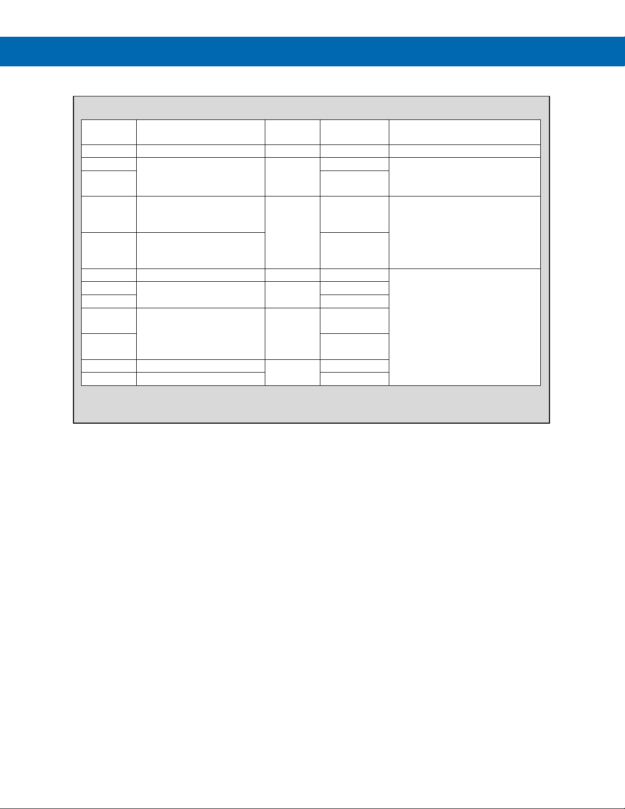
SuperNova PD500 PID Process & Temperature Controllers
Default
Value
RET.T
PV, SV, MV
PV
Models with RET option only.
T-SH
FR.L - FR.H (Note 2)
EU 100 %
T-SL
EU 0 %
T-AH
PV, SV : EUS (-5.0~5.0) %
PV, SV:
T-AL
PV, SV : EUS (-5.0~5.0) %
PV, SV:
REM.E
OFF, ON
OFF
REM.H
5.000
REM.L
1.000
R-SH
FR.L - FR.H (Note 2)
FR.H (Note 2)
R-SL
FR.L (Note 2)
R-AH
EUS (-5.0 ~ 5.0) %
EUS 0.0 %
R-AL
EUS (-5.0 ~ 5.0) %
EUS 0.0 %
G.TRS Parameter Details
Instruction Manual
Parameter Setting range Unit
SL.L - SL.H (Note 3)
However, T-SL < T-SH
MV : EU (95.0~105.0) %
MV : EU (-5.0~5.0) %
1 V ≤ REM.L < REM.H ≤ 5 V V
SL.L - SL.H (Note 3)
However, R-SL < R-SH
1. Set by G.IN parameter UNIT.
2. Selections when thermocouple or RTD input type selected.
3. Selections when mA, VDC, or MVDC input type selected.
Note 1
PV, SV: °C
MV: %
Note 1
Note 1
EUS 0%
MV: EU 100%
EUS 0%
MV: EU 0%
SL.H (Note 3)
SL.H (Note 3)
Parameter Display Condition
Models with RET option only and
TR.MD set to PV or SV.
Models with RET option only.
Models with REM option only.
38
Page 39
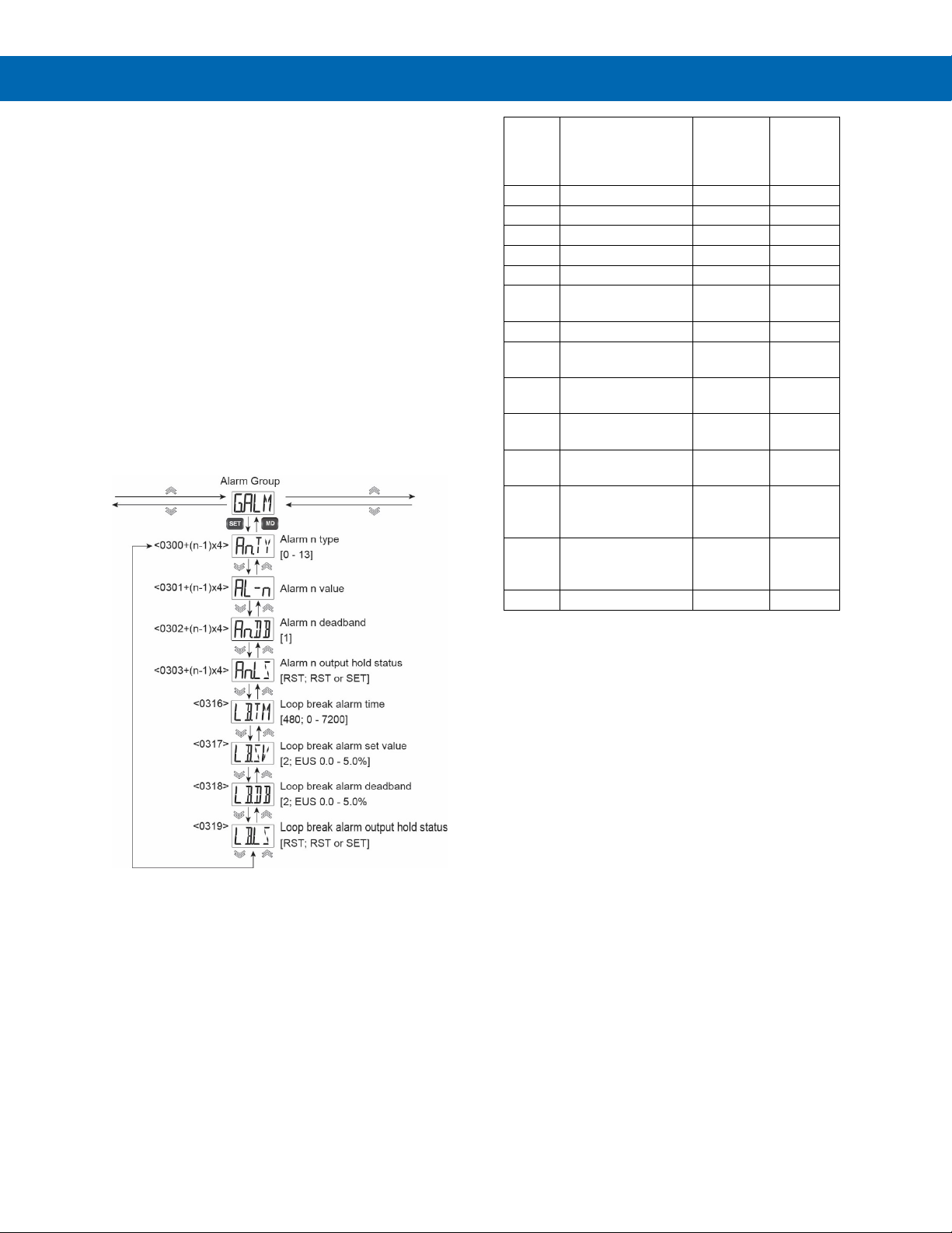
SuperNova PD500 PID Process & Temperature Controllers
An.TY
Alarm Name
Absolute
Standby
0
Alarm Off
Deviation
1
High Absolute
Absolute
2
Low Absolute
Absolute
3
High Deviation
Deviation
4
Low Deviation
Deviation
5
High-Low
Deviation
6
High-Low Range
Deviation
7
High absolute with
Absolute
Yes
8
Low absolute with
Absolute
Yes
9
High deviation with
Deviation
Yes
10
Low deviation with
Deviation
Yes
11
High-Low deviation
Deviation
Yes
12
High-Low range
Deviation
Yes
13
Sensor error
Absolute
Alarm Group (G.ALM)
The Alarm Group contains parameters to establish
alarm conditions for up to four alarms. These alarms
may be assigned to the SUB1 or SUB2 alarm output
relays.
This group also contains the programming of the loop
break alarm (LBA). This is a special type of alarm that
can be assigned to a Sub relay.
During programming of the Alarm Group, references
to “n” in the programming menus refers to the number
1, 2, 3, or 4; the alarm number the parameter applies
to. For example, An.TY could appear as A1.TY,
A2.TY, A3.TY, or A4.TY, each referring to alarm 1, 2,
3, and 4.
Only alarm numbers or LBA settings assigned to the
SUB1 or SUB2 relay in the Sub Relay Group (G.SUB)
will appear in the Alarm Group (G.ALM). Alarm
numbers or LBA settings that are not assigned to a
Sub relay will retain their programming and appear in
the G.ALM menu if again assigned to a Sub relay.
No.
Deviation
standby sequence
standby sequence
standby sequence
standby sequence
with standby
sequence
Instruction Manual
Value or
Deviation
Alarm
With An.TY, you can choose between 'Alarm off' and
13 alarm types listed in the Alarm Type and Number
Table.
Each type is divided into absolute alarm and deviation
alarm, with or without standby mode.
Alarm Number n Type (An.TY)
with standby
sequence
Figure 26. Alarm Type and Number Table
Alarm Number n Value (AL-n)
The AL-n parameter sets the alarm value for alarms
1, 2, 3, or 4; as indicated in the “n” position of the
parameter name.
When the alarm is set as an absolute value alarm, the
setting can be any value within the limits of the input
type. AL-n is entered as the displayed value, in
displayed engineering units, at which the alarm is to
turn on.
When the alarm is set as a deviation alarm, the
setting can be 0 to 100% of the full range of the input,
and is entered in the displayed engineering units, but
the number represents the absolute value of the
deviation amount at which the alarm turns on.
For example, when a type K thermocouple is used,
and the alarm type is set as a high absolute (An.TY
set to 1), the setting range of AL-n cab be -200°C to
1,370°C
When the alarm type is set as a high deviation (An.TY
is set to 3), the setting range of AL-n can be 0.0°C to
1,570.0°C.
Alarm Number n Deadband (An.DB)
The alarm deadband is the different between the set
and reset points of an alarm. An.DB is entered as the
deadband for the alarm, entered in displayed
engineering units. The alarm deadband can be set as
0 to 100% of the full range of the input, regardless of
the alarm being an absolute or deviation alarm
39
Page 40
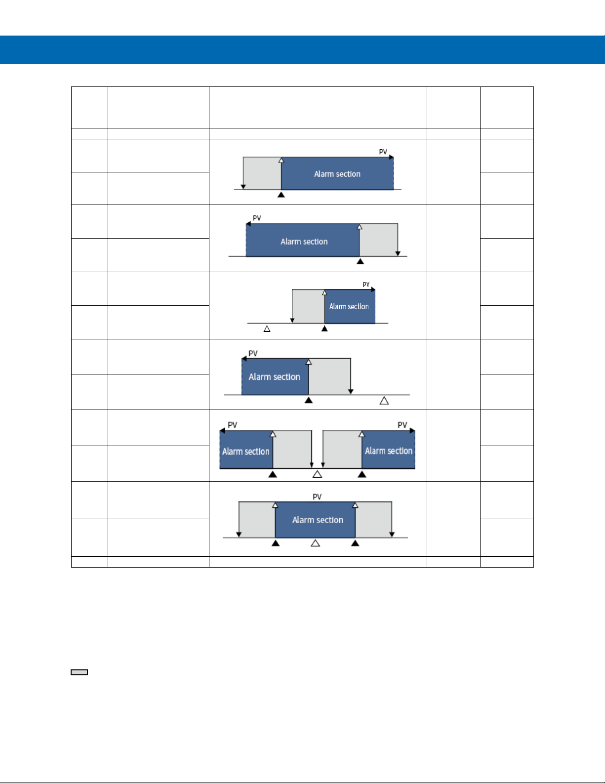
SuperNova PD500 PID Process & Temperature Controllers
An.TY
Alarm Name
Alarm Operation
Absolute
Alarm
Standby
0
Alarm off
1
High absolute
(7)
High absolute with
Yes
2
Low absolute
(8)
Low absolute with
Yes
3
High deviation
(9)
High deviation with
Yes
4 Low deviation
(10)
Low deviation with
Yes
5 High-low deviation
(11)
High-low deviation
Yes
6 High-low range
(12)
High-low range with
Yes
13
Sensor error
Burn-out
Absolute
Instruction Manual
No.
standby sequence
standby sequence
standby sequence
standby sequence
Value or
Deviation
Absolute
Absolute
Deviation
Deviation
Deviation
with standby
sequence
standby sequence
Deviation
: AL-n Alarm value. This is the specific PV value, or for deviation alarms the deviation amount from the SV, when
the alarm activates.
: Set value. For deviation alarms only, indicates the alarm operation as high, low, or both in relation to the SV.
: Alarm activates.
: Alarm deactivates.
: The grey area indicates the alarm deadband, the difference between the activation and reset point of the alarm.
Figure 27. Alarm Operation Description Table
40
Page 41
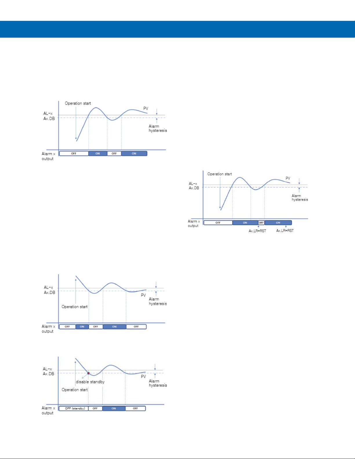
SuperNova PD500 PID Process & Temperature Controllers
Alarm Operation Examples
High Absolute Alarm Operation
The example below illustrates the operation of a high
absolute alarm The alarm turns on when the set point
entered in parameter AL-x is reached, where x can be
any of alarms 1, 2, 3, or 4. The alarm resets when the
PV is below the set point by the Ax.DB number.
Figure 28. High Absolute Alarm Operation
Alarm Standby Mode Operation
Alarms with standby mode will ignore the alarm
condition when the alarm on condition is satisfied at
the time of power on, changes from STOP to RUN
mode, an SV change, or a change to the alarm
program settings. The standby alarm will turn on after
the alarm release condition has been set.
In the below example, when power is applied to the
controller and operation begins, the PV is already in
the alarm state, being greater than the AL-x alarm set
point. In the case of the standard high absolute alarm,
the alarm turns on. However, if a high absolute alarm
with standby is used, the alarm will not turn on until
after the PV passes below deadband and reset point,
and then returns to the higher alarm state.
Figure 29. High Absolute Alarm Operation
without Standby
Alarm Number n Latch Status (An.LS)
An.LS is the alarm latch reset function, where n can
be any of alarms 1, 2, 3, or 4. This parameter is
accessible if the Sub Relay Group (G.SUB) parameter
An.LT is set to ON.
If the Sub Relay Group (G.SUB) parameter An.LT is
set to OFF, this parameter does not appear in the
menu. The alarm will automatically reset when the
alarm condition is cleared (including deadband).
Releasing an Alarm in Latch State
To release an alarm with the latch status ON, the
operator must change this parameter to RST after the
alarm condition has cleared (including the deadband).
As a shortcut, the operator may press the DOWN or
UP arrow keys to reset a latched alarm after the alarm
condition has cleared (including the deadband).
Figure 31. High Absolute Alarm with Latch
Loop Break Alarm (LBA)
The loop break alarm (LBA) is a special type of alarm
used to alert operators to a heater break, wiring error,
output circuit problems, or other issue with the control
loop.
When the control output value in PID or on/off control
modes reaches 0% or 100%, the LBA monitors the
rate of process variable (PV) change. If the PV does
not change by at least the loop break set value
amount over the loop break alarm time, the LBA turns
on.
Reverse Action LBA Operation
When the control output value is 100% in the reverse
action mode (heating control), the LBA alarm output
turns on when the temperature does not rise at least
the LB.SV value within the LB.TM set time. Also,
when the control output value is 0%, the LBA output
turns on when the temperature does not fall at least
the LB.SV value within the LB.TM setting time.
Instruction Manual
Function
Figure 30. High Absolute Alarm Operation
with Standby
41
Page 42
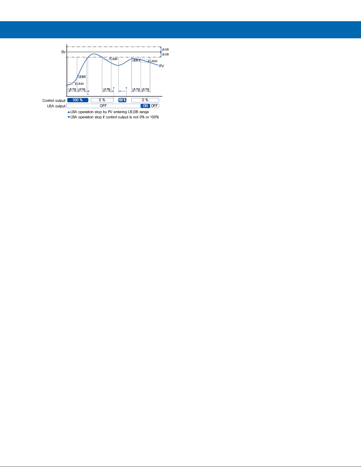
SuperNova PD500 PID Process & Temperature Controllers
Loop Break Detection Time (LB.TM)
The loop break detection time is usually set to about
twice the value of PID coefficient 1. When autotuning is executed, the LB.TM value is automatically
set to twice the PID coefficient 1 value.
However, when on/off control is used, LB.TM is not
set automatically, so it must be input manually by the
user.
Instruction Manual
Figure 32. Loop Break Alarm (LBA) Operation in
Reverse Action Mode
Direct Action LBA Operation
When the control output value is 100% in the direct
action mode (cooling control), the LBA output turns on
when the temperature does not fall at least the LB.SV
value within the LB.TM set time. Also, when the
control output value is 0%, the LBA output turns on
when the temperature does not rise at least the
LB.SV value within the LB.TM set time.
Heating & Cooling Control LBA Operation
When OUT1 and OUT2 are both configured for
control outputs, the controller automatically enters
heating and cooling mode. In heating and cooling
mode, the controller is automatically set to reverse
acting. However, the LBA operates as follows.
When the control output value is 100% on the heating
output (H), the LBA alarm output turns on when the
temperature does not rise at least the LB.SV value
within the LB.TM set time.
When the control output value is 100% on the cooling
output (C), the LBA alarm output turns on when the
temperature does not rise at least the LB.SV value
within the LB.TM set time.
LBA Alarm Clear
The LBA is automatically released under the following
conditions.
• When the difference between the set value
(SV) and process variable (PV) is less than
or equal to the Loop Break Alarm Deadband
(LB.DB) value.
• When there is no sub relay output assigned
to the LBA.
• When the controller is set to the STOP state.
• When performing an auto-tune.
When the control output reaches 100% or 0%, an
alarm is generated if the change of the temperature
deviation after LB.TM time does not change by more
than the Loop Break Alarm Set Value (LB.SV).
Loop Break Alarm Deadband (LB.DB)
Loop Break Set Value (LB.SV)
To prevent malfunctions of the loop break alarm
during normal control, set the Loop Break Alarm
Deadband (LB.DB). If the PV enters the range of SV ±
LB.DB, the LBA will not turn on, or turn off if already
on.
The LBA will only work if the PV is less than SVLB.DB or if PV is greater than SV + LB.DB.
Loop Break Alarm Latch Status (LB.LS)
LB.LS is the loop break alarm latch reset function.
This parameter is accessible if the Sub Relay Group
(G.SUB) parameter LB.LT is set to ON.
If the Sub Relay Group (G.SUB) parameter LB.LT is
set to OFF, this parameter does not appear in the
menu. The alarm will automatically reset when the
alarm condition is cleared (including deadband).
Releasing a Loop break Alarm in Latch State
To release a loop break alarm with the latch status
ON, the operator must change this parameter to RST
after the loop break alarm condition has cleared.
As a shortcut, the operator may press the DOWN or
UP arrow keys to reset a latched alarm after the alarm
condition has cleared.
42
Page 43
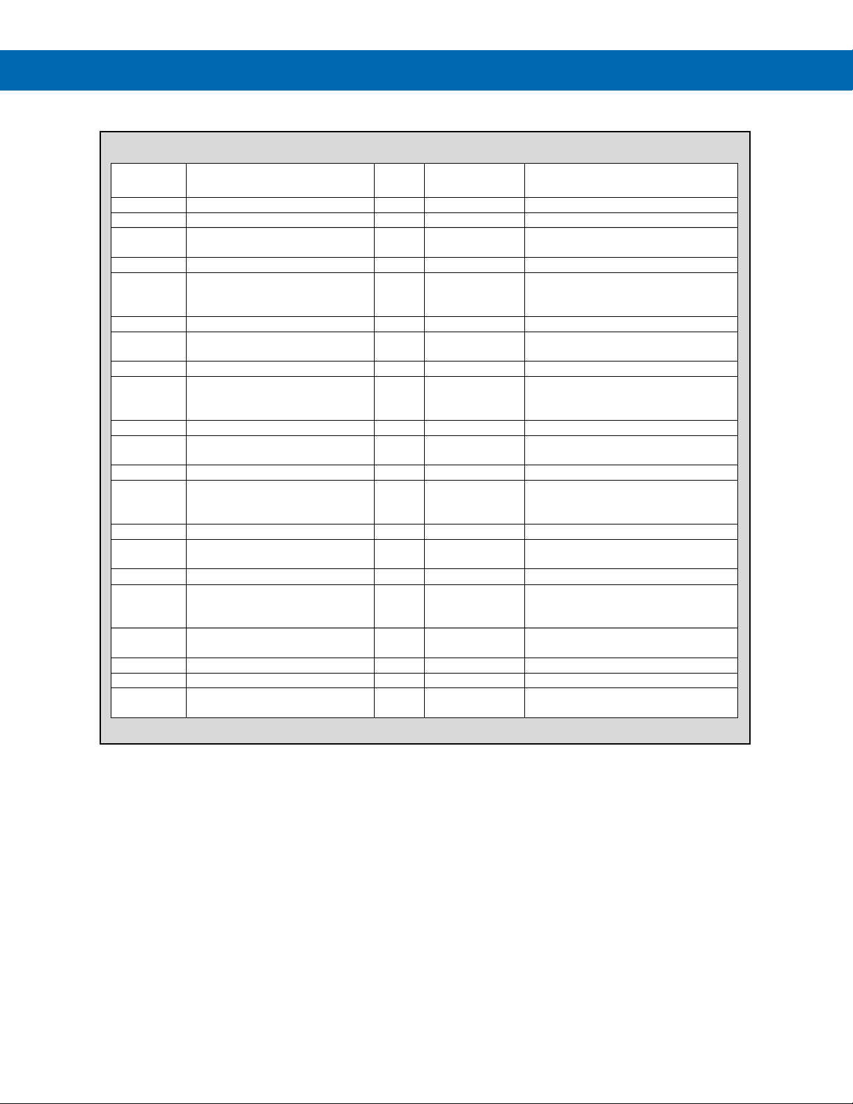
SuperNova PD500 PID Process & Temperature Controllers
Value
RET.T
PV, SV, MV
PV
Models with RET option only.
A1.TY
0 - 13 3
G.SUB parameter SUBx is ALM1
AL-1
Absolute: EU (0.0 - 100.0) %
Deviation: EUS (0.0 - 100.0) %
G.SUB parameter SUBx is ALM1
G.ALM parameter A1.TY ≠ OFF (0)
A1.DB
EUS (0.0 - 100.0) %
Note 1
1.0 ℃
A1.LS
RST, SET
G.SUB parameter SUBx is ALM1
G.ALM parameter A1.TY ≠ OFF (0)
A2.TY
0 – 13 10
G.SUB parameter SUBx is ALM2
AL-2
Absolute: EU (0.0 - 100.0) %
Deviation: EUS (0.0 - 100.0) %
G.SUB parameter SUBx is ALM2
G.ALM parameter A2.TY ≠ OFF (0)
A2.DB
EUS (0.0 - 100.0) %
Note 1
1.0 ℃
A2.LS
RST, SET
G.SUB parameter SUBx is ALM2
G.ALM parameter A2.TY ≠ OFF (0)
A3.TY
0 - 13 1
G.SUB parameter SUBx is ALM3
AL-3
Absolute: EU (0.0 - 100.0) %
Deviation: EUS (0.0 - 100.0) %
G.SUB parameter SUBx is ALM3
G.ALM parameter A3.TY ≠ OFF (0)
A3.DB
EUS (0.0 - 100.0) %
Note 1
1.0 °C
A3.LS
RST, SET
G.SUB parameter SUBx is ALM3
G.ALM parameter A3.TY ≠ OFF (0)
A4.TY
0 - 13 2
G.SUB parameter SUBx is ALM4
AL-4
Absolute: EU (0.0 - 100.0) %
Deviation: EUS (0.0 - 100.0) %
G.SUB parameter SUBx is ALM4
G.ALM parameter A4.TY ≠ OFF (0)
A4.DB
EUS (0.0 - 100.0) %
Note 1
1.0 ℃
A4.LS
RST, SET
G.SUB parameter SUBx is ALM4
G.ALM parameter A4.TY ≠ OFF (0)
LB.TM
0 - 7200
Time
(sec)
G.SUB parameter SUBx is LBA
LB.SV
EUS (0.0 - 5.0)%
Note 1
EUS 0.15%
LB.DB
EUS (0.0 % + 1 digit) - 5.0 %
Note 1
EUS 0.15%
LB.LS
RST, SET
G.SUB parameter SUBx is LBA
G.SUB parameter LB.LT is ON
G.ALM Parameter Details
Parameter Setting range Unit
Note 1 EUS 100.0%
Default
Instruction Manual
Parameter Display Condition
RST
Note 1 EUS 100.0%
RST
Note 1 EU 100.0%
RST
Note 1 EU 0.0%
RST
480
G.SUB parameter A1.LT is ON
G.SUB parameter A2.LT is ON
G.SUB parameter A3.LT is ON
G.SUB parameter A4.LT is ON
1. Set by G.IN parameter UNIT.
RST
43
Page 44
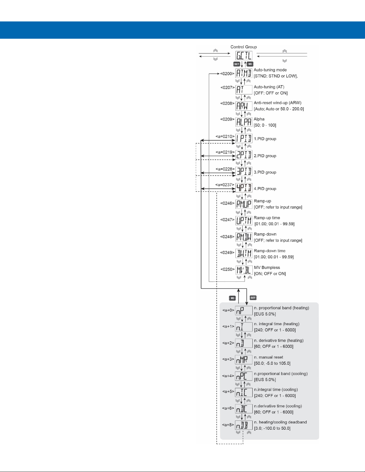
SuperNova PD500 PID Process & Temperature Controllers
Control Group (G.CTL)
The Control Group contains parameters to begin and
adjust auto-tuning, set manual PID parameters, and
perform basic control functions such as set value
ramp up and down behavior.
During programming of the Control Group, references
to “n” in the programming menus refers to the number
1, 2, 3, or 4; the PID group number the parameter
applies to. For example, n.PID could appear as 1.PID,
2.PID, 3.PID, and 4.PID.
Auto-Tuning Process
The auto-tuning function automatically measures,
computes the control system characteristics, and sets
the optimum proportional band (P), integral time (I),
and derivative time (D) constants.
When auto-tuning starts, the control output is
changed temporarily to ON/OFF control and the
optimum PID constants are computed and set from
system response data. The TUNE or [T] icon on the
display will blink during the auto-tune process.
When the auto-tuning process is complete, the TUNE
or [T] icon will turn off and stop blinking.
The time required for AT depends greatly on the
control system.
If the auto-tune process has not ended after 24 hours,
auto-tune process is automatically canceled, and no
PID parameters are set.
If the auto-tune process exceeds 24 hours, the control
output will generate an emergency output, the TUNE
or [T] icon will keep blinking, and AT.E will be
displayed on the PV window.
The SV used for auto-tune is either the SV of the set
value number set by parameter SV.NO, or the remote
SV if the remote SV input (REM) is selected.
Instruction Manual
44
Page 45
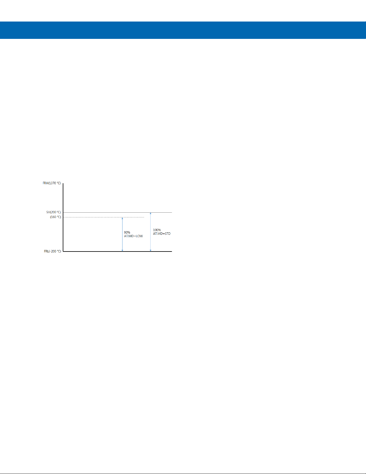
SuperNova PD500 PID Process & Temperature Controllers
Auto-Tuning Mode (AT.MD)
There are two types of auto-tuning (AT): standard
type and low PV type.
Standard type auto-tuning is auto-tuning based on set
value (SV).
Low PV type auto-tuning is auto-tuning based on a
value 10% lower than set value (SV).
When low PV type auto-tuning is performed, the
selected SV is displayed on the device, but the actual
operation executes the auto-tuning at SV minus 10%.
For example, if the SV is set to 200°C with a type k
thermocouple input type, and the low PV type autotuning is performed, the SV displayed on the device
remains 200°C, but the actual auto-tune operation
executes the auto-tuning at 160°C.
The calculation formula is as follows.
Target value of low
PV mode auto-tune = (SV – FRL) x 0.9 – FRL
= (200 – (-200)) x 0.9 – FRL
= 160
6. When auto-tuning process has started, the
7. To end the auto-tuning process before it is
If the auto-tuning process is completed successfully,
the P, I, and D values are automatically set. The P, I,
and D parameters are set in the PID group number
that matches the selected set value number during
the auto-tuning process.
For example, if the set value number selected is set
value number 1, then the PID group P, I, and D
parameters set are also from PID group number 1.
If the remove SV input is selected for the set value
number selected, the P, I, and D values will be set in
PID group number 4.
The P, I, and D values are not changed if auto-tuning
process is cancelled, fails, or is otherwise ended
early.
b. Press and hold the front panel keys
TUNE or [T] indicator will blink. This indicator
will turn off when the auto-tuning process is
completed.
automatically completed:
a. Set the Control Group (G.CTL)
b. Press and hold the front panel keys
Instruction Manual
SET and UP for 3 seconds.
parameter Auto-Tune (AT) to OFF.
SET and UP for 3 seconds.
Figure 33. Standard and Low PV Auto-Tuning SV
Auto-Tuning (AT)
This parameter is used to activate the auto-tuning
mode.
If AT is set to ON, or if the front panel SET and UP
keys are held together for 3 seconds when in run
mode, auto-tuning starts.
The AT sequence is as follows:3
1. Select the set value number (SV.NO) to
execute the auto-tuning on. In many
applications, only one SV number will be
used, and the default set value number of
one is used
2. Set the desired set value for the selected set
value number. It is best to auto-tune to a SV
that is in the range the application normally
requires.
3. Select from standard or low PV type in
parameter AT.MD.
4. Verify the controller is set to run mode. RUN
will appear as one of the front panel display
indicators.
5. Begin the auto-tuning process with one of
the following methods:
a. Set the Control Group (G.CTL)
parameter Auto-Tune (AT) to ON.
Anti-Reset Wind-Up (ARW)
When the control output value (MV) reaches the limit
value (OLH, OLL), it executes the anti-reset wind-up
operation to prevent over-integration.
Alpha (ALPA)
The response in a typical closed loop control system
can be broadly divided into response to set value
change and response to disturbance. The normal PID
(one-degree-of-freedom) algorithm has the limitation
that it can only optimize one response for these two
issues. To overcome this limitation, with the
application of the two-degree-of-freedom PID
algorithm, you can optimize the response to the set
value change and obtain an appropriate response to
disturbances.
The ALPHA parameter is used to adjust the response
characteristics to the set value (SV) changes.
If ALPHA is set to 0%, it is the same as the normal
PID control response.
If ALPHA is set to 100%, it may take a long time to
reach a normal state, but overshoot and undershoot
will be minimized.
45
Page 46
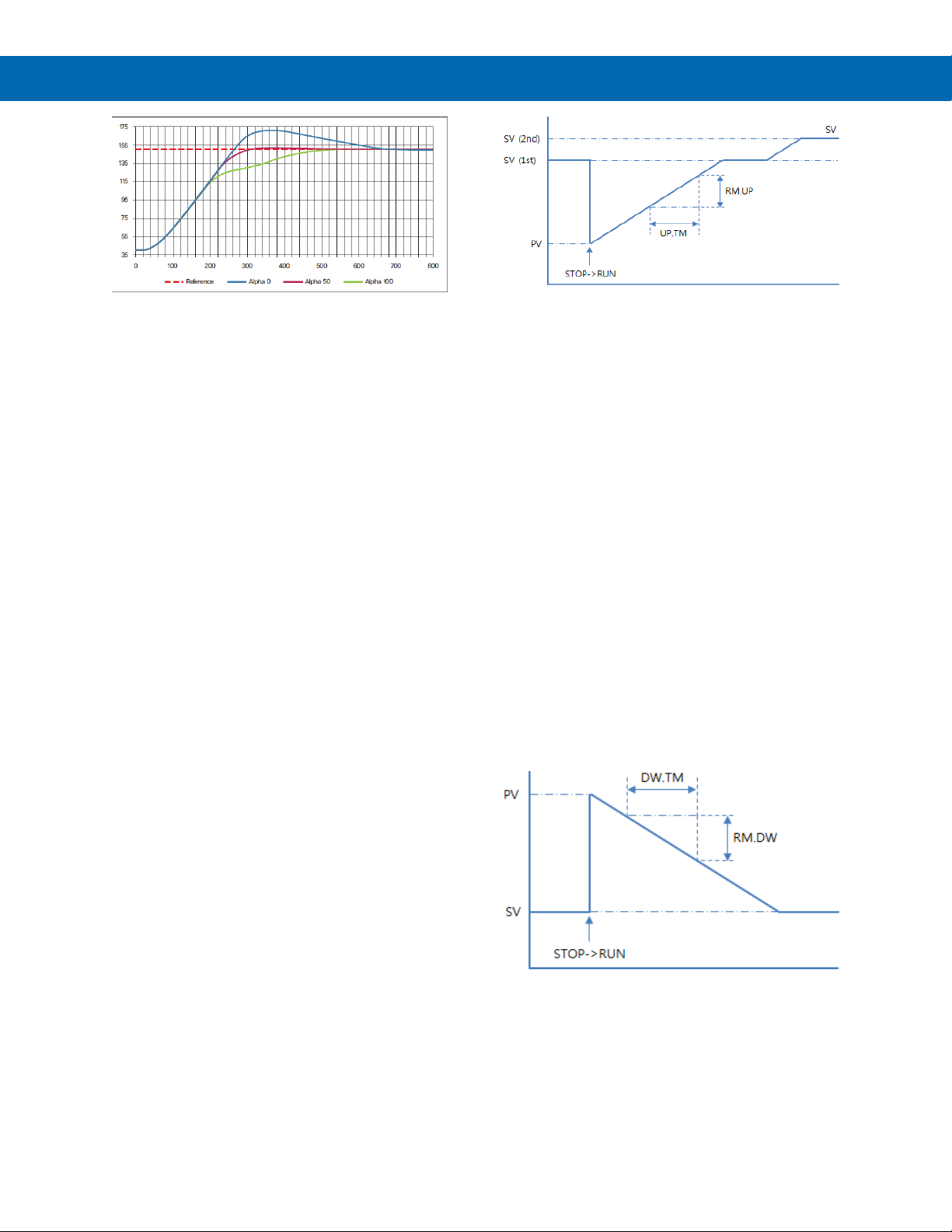
SuperNova PD500 PID Process & Temperature Controllers
Instruction Manual
Figure 34. Response Adjustment with Alpha
When the Integral Time (n.I) parameter is set to 0
(OFF), the Alpha (ALPA) parameter value will be set
to 0 and the ALPA parameter will not appear in the
Control Group (G.CTL), and the n.MR parameter will
be visible.
If the Integral Time (n.I) parameter is not set to 0
(OFF) in the G.CTL group, the Alpha (ALPA) value
will be reset internally to the previously set ALPA
value, the n.MR parameter will not be visible in in the
Control Group (G.CTL), and the Alpha (ALPA)
parameter will be visible.
PID Group Number (n.PID)
N.PID represents selections 1.PID, 2.PID, 3.PID, and
4.PID, PID group numbers 1, 2, 3, and 4. When a
group is selected, the P, I, D, and MR values for that
group are displayed.
n.P, n.I, n.D values are heating PID parameters, and
n.Pc, n.Ic, n.Dc are cooling PID parameters.
The cooling parameters are displayed when Output
Group (G.OUT) parameter OUT2 Control Mode
(CNT2) is set to PID or ONOF. The PID coefficients
are automatically set when auto-tuning is completed,
however these parameters allow them to be set
directly if the user already knows them, or
modifications are desired to the auto-tuning acquired
values.
Figure 35. Set Value Ramp Up
SV Ramp Up (RM.UP)
This parameter sets the amount the set value (SV)
will ramp up over the desired SV ramp up time.
SV Ramp Up Time (UP.TM)
This parameter sets the ramp time required for the
set value (SV) to increase the amount set in the SV
Ramp Up (RM.UP) parameter. The time is entered in
hours and minutes, in the format hh.mm.
For example, if RM.UP is 60°C and UP.TM is 1
minute, the SV value has a ramp up rate of 1.0°C per
second.
SV Ramp Down (RM.DW)
This parameter sets the amount the set value (SV)
will ramp down over the desired SV ramp down time.
SV Ramp Down Time (DW.TM)
This parameter sets the ramp time required for the set
value (SV) to decrease the amount set in the SV
Ramp Down (RM.DW) parameter. The time is entered
in hours and minutes, in the format hh.mm.
Set Value Ramp
When the ramp functions are used, the set value (SV)
changes over time to reach a newly selected set
value. When ramp functions are not used, a newly
selected SV immediately becomes the active SV.
To set the ramp function, the ramp time and the
amount of SV change desired in that ramp time must
be set.
The SV Ramp Up or SV Ramp Down functions are
applied when the SV value is changed, or when
changing from STOP to RUN modes. When the set
SV is changed, the starting SV for the ramp is the
current SV. When changing from STOP to RUN
mode, the SV starts from current PV and ramps to the
new SV.
Figure 36. Set Value Ramp Down
For example, if RM.DW is 60°C and DW.TM is 1
minute, the SV value has a ramp down rate of 1.0°C
per second.
46
Page 47
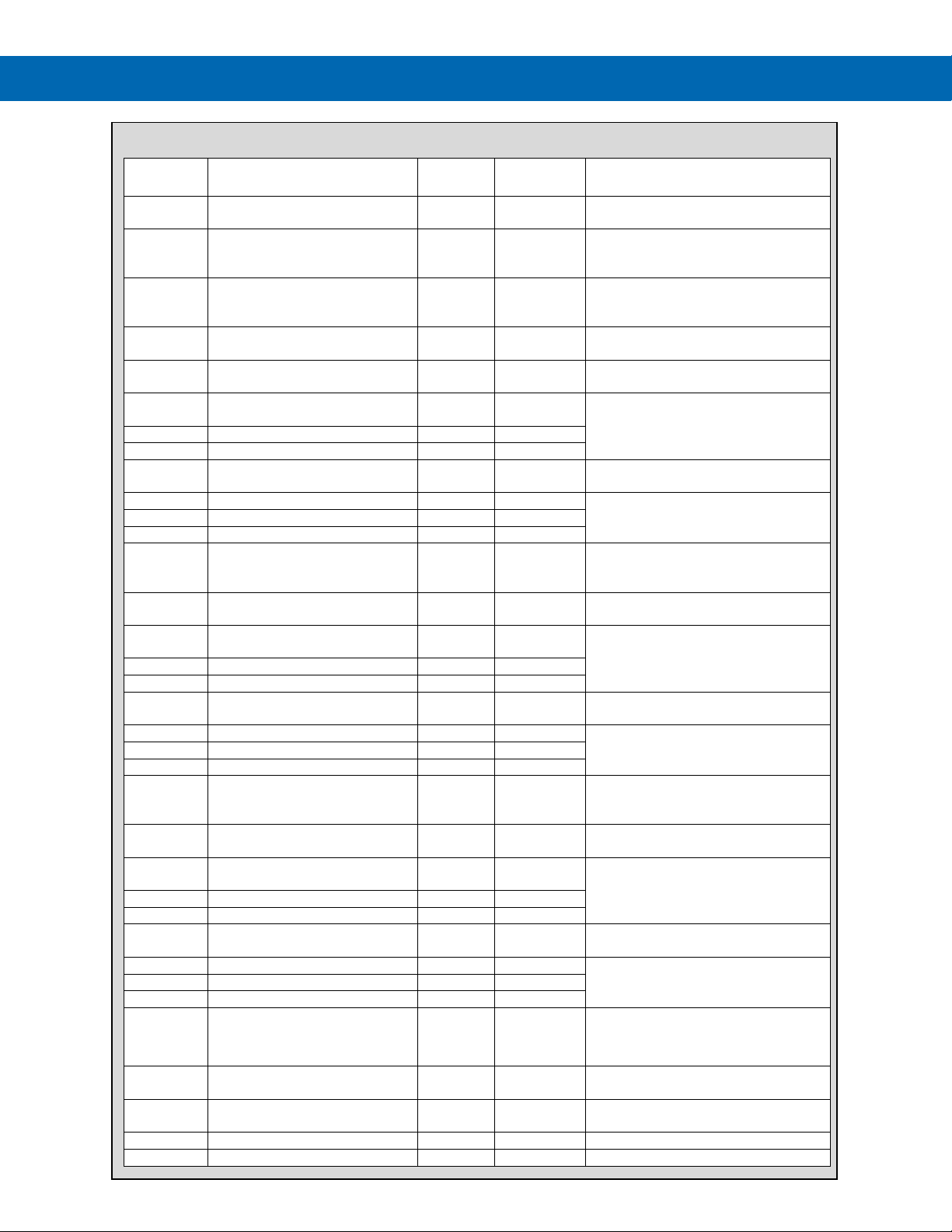
SuperNova PD500 PID Process & Temperature Controllers
Value
AT.MD
STD, LOW
STD
G.OUT parameter CNT1 is PID or
G.OUT parameter CNT2 is PID.
AT
OFF, ON
OFF
G.OUT parameter CNT1 is PID or
Displays only in RUN mode.
ARW
Auto, (50.0 - 200.0) %
%
50.0
G.OUT parameter CNT2 is ONOF or
ALPA
0 – 100 50
G.OUT parameter CNT1 or CNT2
are set to PID.
1.PID
PID No 1 selection
G.OUT parameter CNT1 or CNT2
are set to PID.
1.P
EUS (0.15 - 100.0) % (Note 4)
EUS (0.0 - 100.0) % (Note 5)
Note 1
EUS 5.0 %
1.I
OFF, 1 - 6000
Seconds
240
1.D
OFF, 1 - 6000
Seconds
60
1.MR
-5.0 - 105.0
%
50.0
G.OUT parameter CNT1 is set to
PID and 1.I is set to OFF.
1.Pc
EUS (0.0 - 100.0) %
Note 1
EUS 5.0 %
1.Ic
OFF, 1 - 6000
Seconds
240
1.Dc
OFF, 1 - 6000
Seconds
60
1.DB
-100.0 - 50.0
%
3.0
G.OUT parameter CNT1 is PID or
CNT2 is not set to NONE.
2.PID
PID No 2 selection
G.OUT parameter CNT1 is PID or
G.OUT parameter CNT2 is PID.
2.P
EUS (0.15 - 100.0) % (Note 4)
EUS (0.0 - 100.0) % (Note 5)
Note 1
EUS 5.0 %
2.I
OFF, 1 - 6000
Seconds
240
2.D
OFF, 1 - 6000
Seconds
60
2.MR
-5.0 - 105.0
%
50.0
G.OUT parameter CNT1 is set to
PID and 1.I is set to OFF.
2.Pc
EUS (0.0 - 100.0) %
Note 1
EUS 5.0 %
2.Ic
OFF, 1 - 6000
Seconds
240
2.Dc
OFF, 1 - 6000
Seconds
60
2.DB
-100.0 - 50.0
%
3.0
G.OUT parameter CNT1 is PID or
CNT2 is not set to NONE.
3.PID
PID No 3 selection
G.OUT parameter CNT1 is PID or
G.OUT parameter CNT2 is PID.
3.P
EUS (0.15 - 100.0) % (Note 4)
EUS (0.0 - 100.0) % (Note 5)
Note 1
EUS 5.0 %
3.I
OFF, 1~6000
Seconds
240
3.D
OFF, 1~6000
Seconds
60
3.MR
-5.0 - 105.0
%
50.0
G.OUT parameter CNT1 is set to
PID and 3.I is set to OFF.
3.Pc
EUS (0.0 - 100.0) %
Note 1
EUS 5.0 %
3.Ic
OFF, 1 - 6000
Seconds
240
3.Dc
OFF, 1~6000
Seconds
60
3.DB
-100.0 ~ 50.0
%
3.0
G.OUT parameter CNT1 is PID or
CNT2 is not set to NONE.
4.PID
PID No 4 selection
G.OUT parameter CNT1 is PID or
G.OUT parameter CNT2 is PID.
4.P
EUS (0.15 - 100.0) % (Note 4)
EUS (0.0 - 100.0) % (Note 5)
Note 2
EUS 5.0 %
G.OUT parameter CNT1 is set to
PID.
4.I
OFF, 1 - 6000
Seconds
240
4.D
OFF, 1 - 6000
Seconds
60
G.CTL Parameter Details
Parameter Setting range Unit
Default
G.OUT parameter CNT2 is PID.
PID.
G.OUT parameter CNT1 is set to
PID.
G.OUT parameter CNT2 is set to
PID.
Instruction Manual
Parameter Display Condition
G.OUT parameter CNT2 is PID and
G.OUT parameter CNT1 is set to
PID.
G.OUT parameter CNT2 is set to
PID.
G.OUT parameter CNT2 is PID and
G.OUT parameter CNT1 is set to
PID
G.OUT parameter CNT2 is set to
PID
G.OUT parameter CNT2 is PID and
47
Page 48
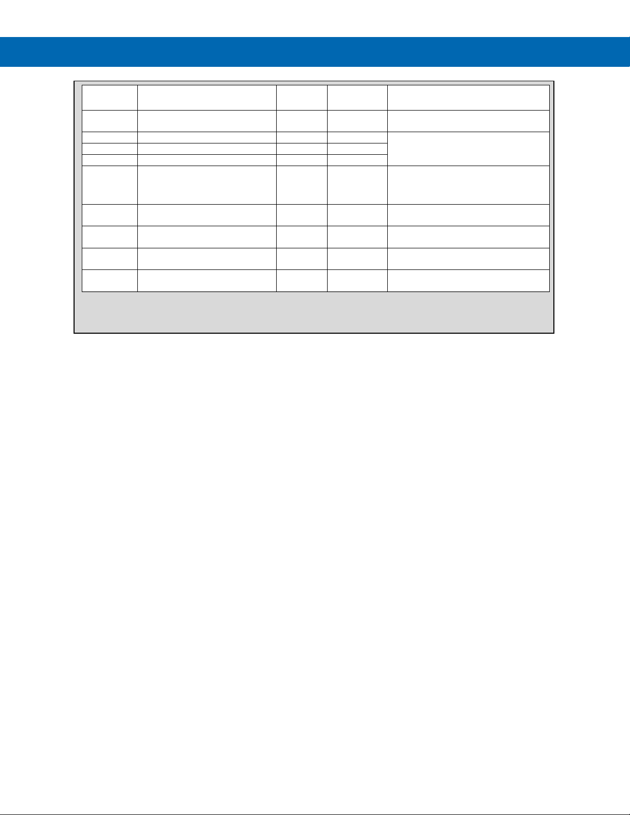
SuperNova PD500 PID Process & Temperature Controllers
Default
4.MR
-5.0 - 105.0
%
50.0
G.OUT parameter CNT1 is set to
PID and 4.I is set to OFF.
4.Pc
EUS (0.0 - 100.0) %
Note 1
EUS 5.0%
4.Ic
OFF, 1 - 6000
Seconds
240
4.Dc
OFF, 1 - 6000
Seconds
60
4.DB
-100.0 - 50.0
%
3.0
G.OUT parameter CNT1 is PID or
CNT2 is not set to NONE.
RM.UP
OFF, EUS
(0.0 % + 1Digit) - 100.0%
Note 1
OFF
UP.TM
00.01 ~ 99.59
hh:mm
01.00
G.SV parameter RM.UP is not set to
OFF.
RM.DW
OFF, EUS
(0.0 + 1Digit) - 100.0%
Note 1
OFF
DW.TM
00:01 - 99:59
hh:mm
01.00
G.SV parameter RM.DW is not set to
OFF.
Instruction Manual
Parameter Setting range Unit
1. Set by G.IN parameter UNIT.
4. Heating or cooling mode, CNT2 is set to None
5. Heating and cooling mode only, CNT2 is set to ONOF or PID.
Value
Parameter Display Condition
G.OUT parameter CNT2 is set to
PID.
G.OUT parameter CNT2 is PID and
48
Page 49
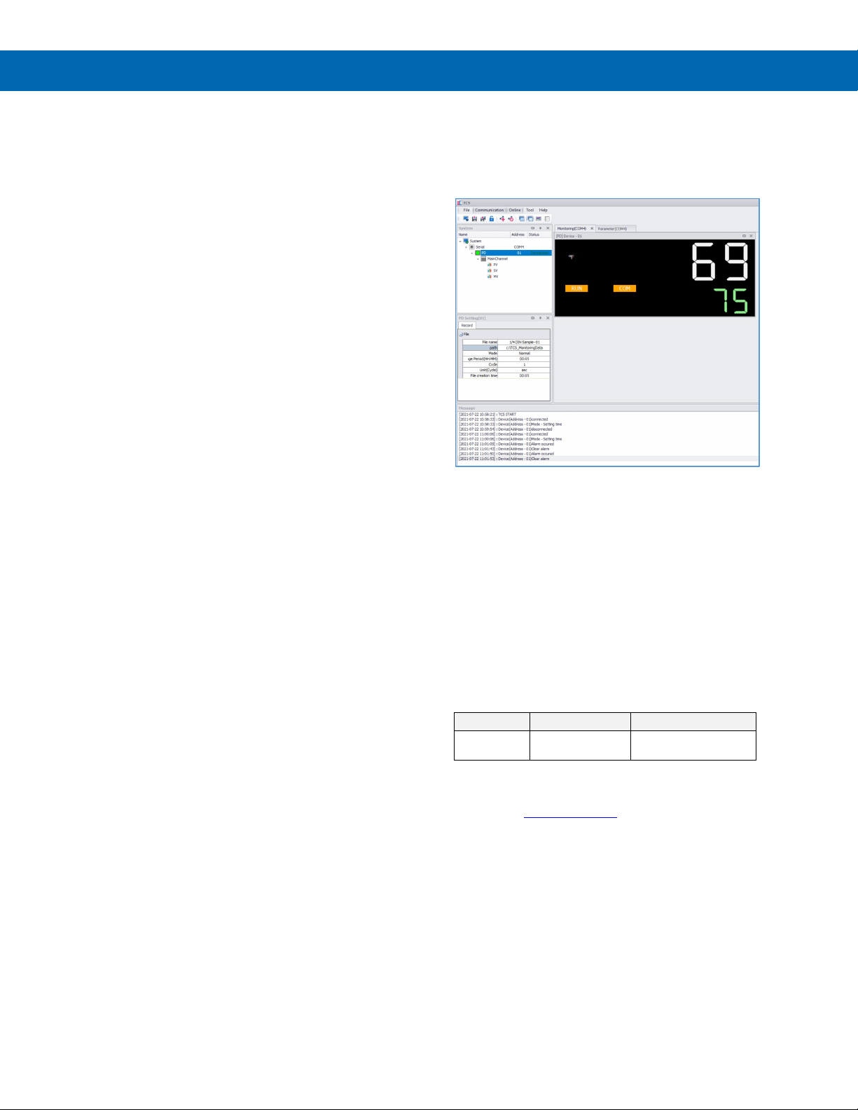
SuperNova PD500 PID Process & Temperature Controllers
Quantity
Model
Description
Isolated Converter
SuperNova TCS Software
The SuperNova line of controllers includes the FREE
SuperNova TCS monitoring and programming
software.
The easiest and quickest way to connect to the
SuperNova TCS software is to use the on-board miniUSB port available on all SuperNova controllers.
This software can be used for monitoring, data
logging, programming, and troubleshooting
SuperNova controllers.
SuperNova TCS software can connect to a maximum
of 31 units when using the RS-485 communications
option. A single unit can be connected via the USB
connection.
Monitoring
SuperNova TCS software can be used to monitor up
to 31 SuperNova controllers on a PC. The screenshot
below shows SuperNova TCS software monitoring a
single SuperNova controller.
Remote Programming
SuperNova TCS software allows all setup parameters
to be programmed remotely from a PC and saved to a
file for reporting or programming other controllers.
We recommend the following sequence for getting the
controller into service using the SuperNova TCS
software:
1. There is no need to apply AC power to the
controller for parameter setup.
2. Connect the controller to the PC with the USB
cable provided.
3. If SuperNova TCS software (TCS) is already
installed in your computer, then double click the
TCS icon or select TCS from your list of
programs by selecting the PD folder, and then
TCS software.
4. If the SuperNova TCS software is not installed,
follow the instructions provided below.
5. Use SuperNova TCS software to configure the
controller for your application.
6. Disconnect the USB cable from the controller.
7. Apply power and signal and check operation of
the controller.
8. Install the controller and put into service.
9. Make any programming adjustments using the
front panel buttons.
Monitoring with RS-485 Connection
SuperNova TCS software may be connected directly
to the controller using the on-board USB connector.
However, if used in the application, it may be
convenient to use the RS-485 connection to connect
to a computer. This method is also required when
monitoring multiple SuperNova controllers.
To connect the SuperNova controllers with the
RS-485 option to a computer, the PDA8485 USB to
RS-485 Isolated Converter is recommended.
One PDA8485-I may support all SuperNova
controllers, up to 31 units, connected.
1 PDA8485-I
Data Acquisition
SuperNova TCS software provides a convenient way
to collect the data from the SuperNova controller. The
user can select the logging time interval. Data can be
written to a file, which can then be imported into a
spreadsheet or other application or viewed in the
SuperNova TCS software.
SuperNova TCS Installation
1. Go to www.predig.com and download the
SuperNova TCS software.
2. Read all SuperNova and SuperNova TCS
instructions.
3. Download Installation file to computer
4. Double-click installation file to open it
5. Double-click the appropriate setup file to begin
installation:
6. TCS-1.0.2_(x86).exe for 32-bit operating
systems.
7. TCS-1.0.2_(x64).exe for 64-bit operating
systems.
8. Follow on-screen instructions
Instruction Manual
USB to RS-485
49
Page 50
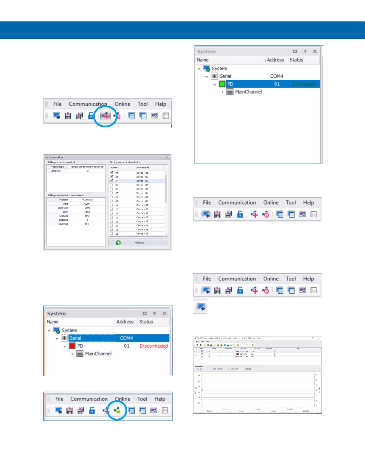
SuperNova PD500 PID Process & Temperature Controllers
Running SuperNova TCS the First Time
The first time SuperNova TCS is run it is necessary to
set up the serial communication settings of the
program.
Click the Add Serial Communications icon in the
upper left menu, as identified below.
Instruction Manual
Select the communication port, protocol, baud rate,
serial communications parameters, and addressed of
the controller(s) connected. Once the configuration is
complete, select Add Port.
Note that for USB connections, it may be required to
check what virtual com port is being used for the USB
connection in the computer’s Device Manager tool.
Once the port is added, the port(s) and controllers(s)
selected will appear in the System menu box on the
left side of the screen.
The image below shows on controller assigned
address 01 connected to COM4.
SuperNova TCS Main menu
The main SuperNova TCS menu consist of various
commands as show below.
For a more detailed listing of all SuperNova TCS
software capabilities and controls, refer to the Help
selection in the Help menu for a complete software
manual.
Top Level Menus
The File, Communication, and Online menus have
icons that appear automatically below the menus.
To connect to the controller(s) assigned to the active
port(s), click the Connect icon shown below.
When connected, the Disconnected message for the
port will be replaced with a “Connected” message,
and monitoring will begin for the assigned addresses.
Load monitoring data
Open the Graph Viewer to see previously data logged
information in chart or table form and export it into
various file formats.
50
Page 51
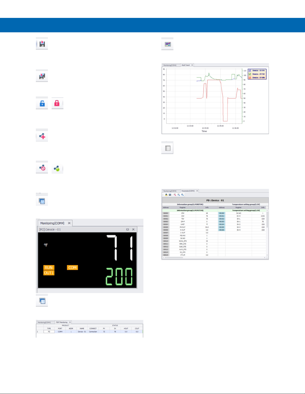
SuperNova PD500 PID Process & Temperature Controllers
Instruction Manual
Monitoring data saving start
Starts data logging for the selected units in the
System menu list.
Start saving all the monitoring data
Starts data logging for all connected units on a port.
/ Lock or Unlock
Locks or unlocks all the functions of the SuperNova
TCS software.
Add serial communications
Opens the new serial communications menu to setup
a new port.
/ Connect or Disconnect
Connect or disconnect all the controllers connected a
port.
Multitrend
Opens the trend graph monitoring screen for all
connected controllers.
Parameter
Opens the parameter list and parameter settings for
the selected controller. Changes to the parameters
and setup may be done from this screen.
Parameter configurations may be uploaded from the
controller, downloaded to the controller, saved as a
file, or loaded from a file.
Monitoring
Opens the graphical monitoring screen for the
selected controller.
Text Monitoring
Opens a chart listing the monitoring information for all
connected controllers.
Tool Menu
This menu is used to open the Graph Viewer to see
previously data logged information in chart or table
form and export it into various file formats.
It also contains the Settings menu. The Settings menu
is used to select English or Spanish language text,
and to set a password to lock the software setup from
changes.
Help Menu
Use the Help selection to open the SuperNova TCS
complete manual. Use the Program Info selection to
view the software version information.
51
Page 52
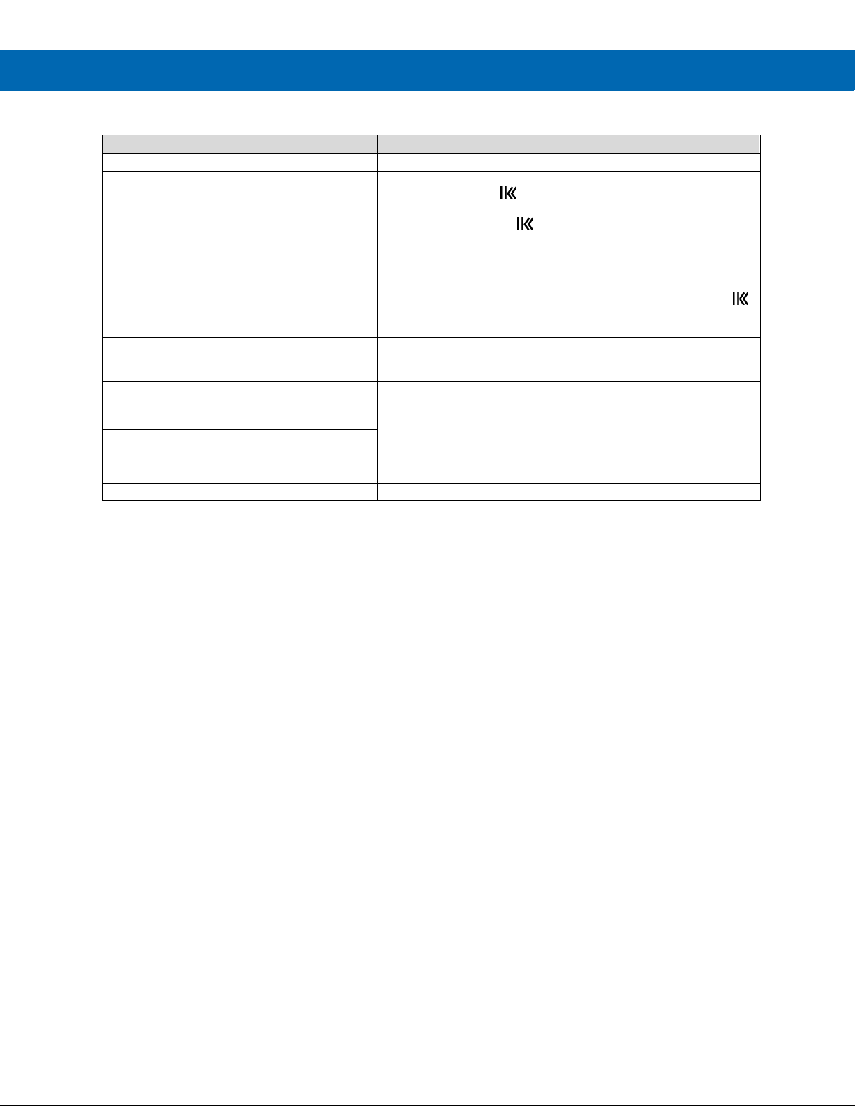
SuperNova PD500 PID Process & Temperature Controllers
Symptom
Check/Action
No display at all
Check power at power terminals.
The controller is in STOP mode. Change it to RUN mode by
holding the shift key for 2 seconds.
Verify the controller is not in STOP mode. Change it to RUN mode
mode.
The controller displays LOCK in the SV
menu parameters.
The controller settings lock is enabled. Hold the SET and shift
back on when changes are competed.
The controller is in manual mode. Change the controller to
seconds.
The controller is in heating and cooling mode
To operate as a heating or cooling controller, disable the Output
(DIR) for cooling control.
Other symptoms not described above
Call Technical Support for assistance.
Troubleshooting Tips
The MV display is blank.
by holding the shift key for 2 seconds.
The control outputs are not working.
Verify the controller is not in manual mode. If in manual mode, the
MANU indicator will display on the controller. Hold the SET and
down keys for 3 seconds to change from manual to automatic
Instruction Manual
window when attempting to change the SV or
The control outputs are not changing and
the MANU light is on the display
and only heating or cooling mode is needed.
The MV display shows a H or C when heating
and cooling mode is not required.
Note: Certain sequences of events can cause unexpected results. To solve these issues, it is best to start fresh from
factory defaults and use the manual as a step-by-step programming guide, rather than a random approach to
programming. To reset the controller to factory defaults, use the Parameter Initialization (P.INT) parameter in the
Settings Group (G.SET).
In addition, for best results, we recommend using the free SuperNova TCS software to review all of the controller
settings.
keys for 3 seconds to turn the lock off. Consider turning the lock
automatic mode by holding the SET and down keys for three
Group (G.OUT) parameter CNT2. Set CNT2 to NONE. This will
disable the heating and cooling output indication of H or C before
the MV % output display digits.
After setting CNT2 to NONE, set the Group (G.OUT) parameter
O.ACT to reverse acting (REV) for heating control, or direct acting
52
Page 53
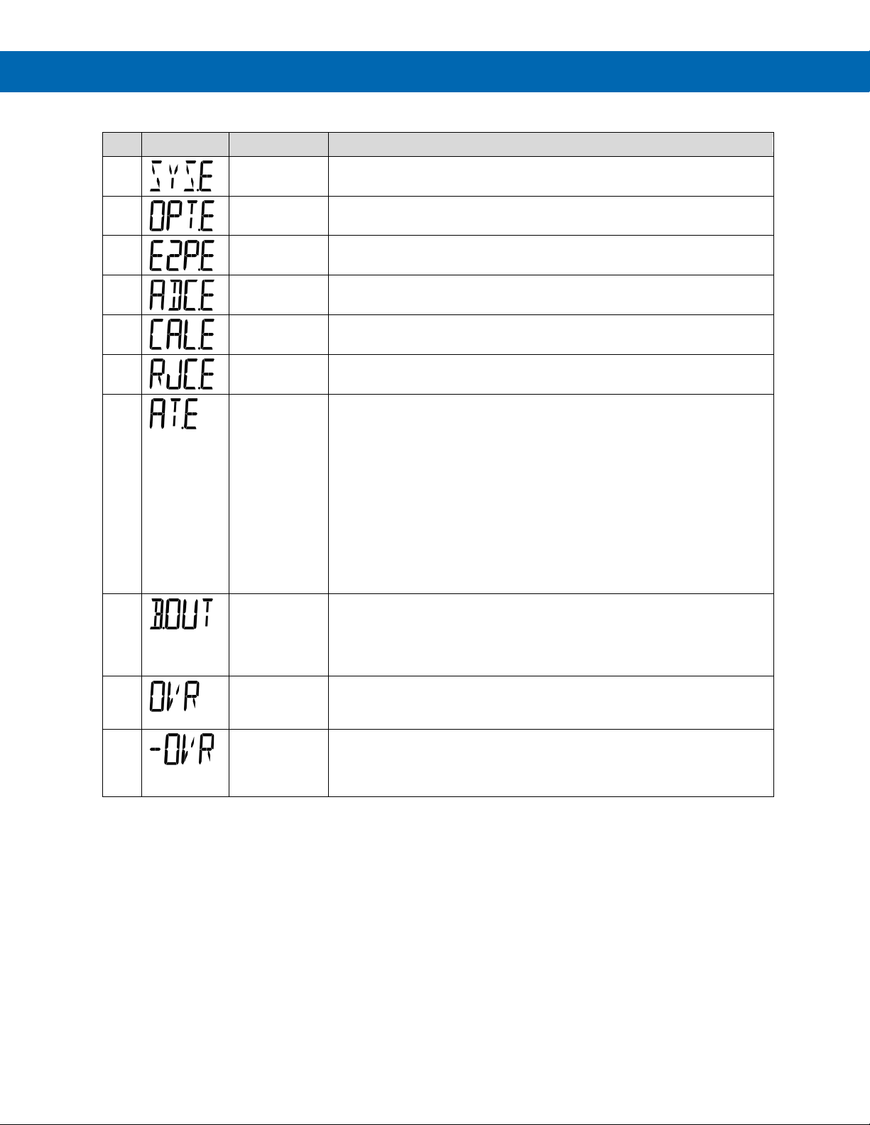
SuperNova PD500 PID Process & Temperature Controllers
No
Display
Error Type
Cause and Action
1 System Data
System data error (please contact technical support)
2 Option Data
Option data error (please contact technical support)
3 EEPROM
EEPROM error (please contact technical support)
4 AD Converter
AD Converter error (please contact technical support)
5 Calibration
Calibration value setting error (please contact technical support)
6 RJC
Reference junction compensation error (please contact technical support)
7 Auto-tuning
Auto-tuning has taken more than 24 hours to complete, which will cancel
24 hours, manually setting the PID values will be required.
8
The sensor appears to be disconnected. Check sensor wiring and the
and minimum signal.
9 +Over
This error occurs when the input signal exceeds +5% (full scale) of the
Confirm the correct input type is selected for the attached sensor.
10 -Over
This error occurs when the input signal is less than -5% (full scale) of the
the sensor setting state.
Error Messages
the auto-tuning process.
Check if the programmed input type and actual sensor match.
Confirm that when the control output value (MV) indicates 100%, the output
signal is correct. If it is not, please contact technical support.
Confirm the PV changes if the control output value (MV) is 100 If the PV
does not change enough to allow an auto-tuning within 24 hours, check the
system wiring and other equipment.
Confirm the PV changes when the control output value is 0%. If the PV
does not change enough to allow an auto-tuning within 24 hours, check the
system wiring and other equipment.
If the system is too slow to respond, and auto-tuning would take more than
Instruction Manual
Burnout
condition of the sensor.
Confirm the correct input type is selected for the attached sensor.
Measure the input signal, and verify it is within the sensor input maximum
sensor input maximum range.
sensor input minimum range.
Confirm the correct input type is selected for the attached sensor. Check
53
Page 54
SuperNova PD500 PID Process & Temperature Controllers
Address
D-register
Parameter
R/W
RAM
(Only)
DEC
HEX
DEC
HEX
40001
9C41 0 0000
CPV
Current PV
RO O 40002
9C42 1 0001
CSV
Current set value
RO O 40003
9C43 2 0002
TSV
Final set value
RO
O
40004
9C44 3 0003
DP-P
Number of decimal
points
RO
O
40005
9C45 4 0004
UNIT
Unit
RO
O
40006
9C46 5 0005
MVOUT
Output level %
RO
O
40007
9C47 6 0006
OUT1 (Heat)
Heating output %
RO
O
40008
9C48 7 0007
OUT2 (Cool)
Cooling output %
RO
O
40009
9C49 8 0008
PID.NO
PID number
RO O 40010
9C4A 9 0009
SV.NO
SV number
RO O 40011
9C4B
10
000A
NOW_STS
Current state
RO O 40012
9C4C
11
000B
ERR_STS
Error status
RO
O
40013
9C4D
12
000C
SUB_STS
Sub output status
RO
O
40014
9C4E
13
000D
ALM_STS
Alarm status
RO O 40015
9C4F
14
000E
DI_STS
DI status
RO O 40018
9C52
17
0011
R/S
Run/stop mode
RO O 40019
9C53
18
0012
AT
Auto-tuning
RO
O
40020
9C54
19
0013
A/M
Auto/manual mode
RO
O
40021
9C55
20
0014
AL1.M
ALM1 monitoring
RO O 40022
9C56
21
0015
AL2.M
ALM2 monitoring
RO O 40023
9C57
22
0016
AL3.M
ALM3 monitoring
RO O 40024
9C58
23
0017
AL4.M
ALM4 monitoring
RO
O
40025
9C59
24
0018
LBA.M
LBA monitoring
RO
O
40026
9C5A
25
0019
HBA.M
HBA monitoring
RO O 40032
9C60
31
001F
A/M
Auto/manual mode
RW
O
40033
9C61
32
0020
MV IN
Manual output
% value
RW
O
40034
9C62
33
0021
R/S
Run/stop mode
RW
O
40042
9C6A
41
0029
SYS
System data
RO 40043
9C6B
42
002A
OPT
Option data
RO 40044
9C6C
43
002B
SP1
Special data (1)
RO 40045
9C6D
44
002C
SP2
Special data (2)
RO
40046
9C6E
45
002D
FWV
Firmware version
RO
Address
D-register
Parameter
R/W
RAM
(Only)
DEC
HEX
DEC
HEX
40101
9CA5
100
0064
SV.NO
Set value number selection
R/W 40102
9CA6
101
0065
SV-H
SV setting high limit value
R/W
40103
9CA7
102
0066
SV-L
SV setting low limit value
R/W
40104
9CA8
103
0067
SV-1
Set value 1
R/W 40105
9CA9
104
0068
SV-2
Set value 2
R/W 40106
9CAA
105
0069
SV-3
Set value 3
R/W 40107
9CAB
106
006A
SV-4
Set value 4
R/W
Modbus Register Tables
Fixed Modbus Tables
General Process and Indication, Address 0 - 99
Instruction Manual
Set Value Group (G.SV), Address 100 - 199
54
Page 55
SuperNova PD500 PID Process & Temperature Controllers
Address
D-register
Parameter
R/W
RAM
(Only)
DEC
HEX
DEC
HEX
40201
9D09
200
00C8
AT.MD
Auto-tuning mode
R/W 40202
9D0A
207
00C9
AT
Auto-tuning
R/W O 40205
9D0D
208
00CC
ARW
Anti-reset Windup
R/W 40206
9D0E
209
00CD
ALPA
Alpha
R/W
- - - - PID.N
PID number
R/W
O
40211
9D13
210
00D2
1.P
Heating proportional band
R/W 40212
9D14
211
00D3
1.I
Heating integral time
R/W 40213
9D15
212
00D4
1.D
Heating derivative time
R/W 40214
9D16
213
00D5
1.MR
Manual reset
R/W
40215
9D17
214
00D6
1.Pc
Cooling proportional band
R/W
40216
9D18
215
00D7
1.Ic
Cooling integral time
R/W
40217
9D19
216
00D8
1.Dc
Cooling derivative time
R/W
40218
9D1A
217
00D9 - -
-
40219
9D1B
218
00DA
1.DB
Heating / cooling
deadband
R/W
40220
9D1C
219
00DB
2.P
Heating proportional band
R/W 40221
9D1D
220
00DC
2.I
Heating integral time
R/W 40222
9D1E
221
00DD
2.D
Heating derivative time
R/W 40223
9D1F
222
00DE
2.MR
Manual reset
R/W
40224
9D20
223
00DF
2.Pc
Cooling proportional band
R/W
40225
9D21
224
00E0
2.Ic
Cooling integral time
R/W 40226
9D22
225
00E1
2.Dc
Cooling derivative time
R/W 40227
9D23
226
00E2 - -
-
40228
9D24
227
00E3
2.DB
Heating / cooling
deadband
R/W
40229
9D25
228
00E4
3.P
Heating proportional band
R/W 40230
9D26
229
00E5
3.I
Heating integral time
R/W 40231
9D27
230
00E6
3.D
Heating derivative time
R/W 40232
9D28
231
00E7
3.MR
Manual reset
R/W
40233
9D29
232
00E8
3.Pc
Cooling proportional band
R/W
40234
9D2A
233
00E9
3.Ic
Cooling integral time
R/W 40235
9D2B
234
00EA
3.Dc
Cooling derivative time
R/W 40236
9D2C
235
00EB - -
-
40237
9D2D
236
00EC
3.DB
Heating / cooling
deadband
R/W
40238
9D2E
237
00ED
4.P
Heating proportional band
R/W 40239
9D2F
238
00EE
4.I
Heating integral time
R/W
40240
9D30
239
00EF
4.D
Heating derivative time
R/W
40241
9D31
240
00F0
4.MR
Manual reset
R/W
40242
9D32
241
00F1
4.Pc
Cooling proportional band
R/W
40243
9D33
242
00F2
4.Ic
Cooling integral time
R/W 40244
9D34
243
00F3
4.Dc
Cooling derivative time
R/W
40245
9D35
244
00F4 - -
-
40246
9D36
245
00F5
4.DB
Heating / cooling
deadband
R/W
40247
9D37
246
00F6
RM.UP
Ramp-up temperature
R/W 40248
9D38
247
00F7
UP.TM
Ramp-up time
R/W
40249
9D39
248
00F8
RM.DW
Ramp-down temperature
R/W
40250
9D3A
249
00F9
DW.TM
Ramp-down time
R/W
Control Group (G.CTL), Address 200 - 299
Instruction Manual
55
Page 56
SuperNova PD500 PID Process & Temperature Controllers
Address
D-register
Parameter
R/W
RAM
(Only)
DEC
HEX
DEC
HEX
40301
9D6D
300
012C
A1.TY
Alarm 1 type
R/W 40302
9D6E
301
012D
AL-1
Alarm 1 set value
R/W 40303
9D6F
302
012E
A1.DB
Alarm 1 deadband
R/W 40304
9D70
303
012F
A1.LS
Alarm 1 output hold status
R/W
O
40305
9D71
304
0130
A2.TY
Alarm 2 type
R/W
40306
9D72
305
0131
AL-2
Alarm 2 set value
R/W 40307
9D73
306
0132
A2.DB
Alarm 2 deadband
R/W 40308
9D74
307
0133
A2.LS
Alarm 2 output hold status
R/W O 40309
9D75
308
0134
A3.TY
Alarm 3 type
R/W
40310
9D76
309
0135
AL-3
Alarm 3 set value
R/W
40311
9D77
310
0136
A3.DB
Alarm 3 deadband
R/W
40312
9D78
311
0137
A3.LS
Alarm 3 output hold status
R/W
O
40313
9D79
312
0138
A4.TY
Alarm 4 type
R/W 40314
9D7A
313
0139
AL-4
Alarm 4 set value
R/W 40315
9D7B
314
013A
A4.DB
Alarm 4 deadband
R/W 40316
9D7C
315
013B
A4.LS
Alarm 4 output hold status
R/W
O
40317
9D7D
316
013C
LB.TM
Loop break alarm time
R/W
40318
9D7E
317
013D
LB.SV
Loop break alarm temperature
R/W 40319
9D7F
318
013E
LB.DB
Loop break alarm deadband
R/W 40320
9D80
319
013F
LB.LS
Loop break alarm latch status
R/W O 40321
9D81
320
0140
HB-1
Heater break alarm 1 current
R/W
40322
9D82
321
0141
H1.DB
Heater break alarm 1 current
deadband
R/W
40323
9D83
322
0142
HB-2
Heater break alarm 2 type
R/W
40324
9D84
323
0143
H2.DB
Heater break alarm 2 current
deadband
R/W
40325
9D85
324
0144
HB.LS
Heater break alarm latch status
R/W
O
Address
D-register
Parameter
R/W
RAM
(Only)
DEC
HEX
40401
9DD1
400
0190
RET.T
Retransmission output type
R/W
40402
9DD2
401
0191
RET.H
Retransmission output high
scale value
R/W
40403
9DD3
402
0192
RET.L
Retransmission output low
scale value
R/W
40404
9DD4
403
0193
T-AH
Retransmission output high
adjust value
R/W
40405
9DD5
404
0194
T-AL
Retransmission output low
adjust value
R/W
40406
9DD6
405
0195
REM.E
Remote input selection
R/W
40407
9DD7
406
0196
REM.H
Remote input high voltage
setting
R/W
40408
9DD8
407
0197
REM.L
Remote input low voltage
setting
R/W
40409
9DD9
408
0198
R-SH
Remote input high scale value
R/W
40410
9DDA
409
0199
R-SL
Remote input low scale value
R/W
40411
9DDB
410
019A
R-AH
Remote input adjust high
value
R/W
40412
9DDC
411
019B
R-AL
Remote input adjust low value
R/W
Alarm Group (G.ALM) Address, 300 - 399
Instruction Manual
Transmit Group (G.TRS), Address 400 - 499
56
Page 57
SuperNova PD500 PID Process & Temperature Controllers
Address
D-register
Parameter
R/W
RAM
(Only)
DEC
HEX
DEC
HEX
40501
9E35
500
01F4
SUB1
Sub1 output type
R/W 40502
9E36
501
01F5
SUB2
Sub2 output type
R/W 40503
9E37
502
01F6
SUB3
Sub3 output type
R/W 40504
9E38
503
01F7
SUB4
Sub4 output type
R/W
40505
9E39
504
01F8
A1.ND
Alarm 1 on delay time
R/W
40506
9E3A
505
01F9
A1.FD
Alarm 1 off delay time
R/W 40507
9E3B
506
01FA
A1.EC
Alarm 1 contact type
R/W 40508
9E3C
507
01FB
A1.LT
Alarm 1 output lock
R/W 40509
9E3D
508
01FC
A2.ND
Alarm 2 on delay time
R/W
40510
9E3E
509
01FD
A2.FD
Alarm 2 off delay time
R/W
40511
9E3F
510
01FE
A2.EC
Alarm 2 contact type
R/W
40512
9E40
511
01FF
A2.LT
Alarm 2 output lock
R/W
40513
9E41
512
0200
A3.ND
Alarm 3 on delay time
R/W 40514
9E42
513
0201
A3.FD
Alarm 3 off delay time
R/W 40515
9E43
514
0202
A3.EC
Alarm 3 contact type
R/W 40516
9E44
515
0203
A3.LT
Alarm 3 output lock
R/W
40517
9E45
516
0204
A4.ND
Alarm 4 on delay time
R/W
40518
9E46
517
0205
A4.FD
Alarm 4 off delay time
R/W 40519
9E47
518
0206
A4.EC
Alarm 4 contact type
R/W 40520
9E48
519
0207
A4.LT
Alarm 4 output lock
R/W 40521
9E49
520
0208
LB.ND
Loop break alarm on delay
R/W
40522
9E4A
521
0209
LB.FD
Loop break alarm off delay
R/W
40523
9E4B
522
020A
LB.EC
Loop break alarm electric
Contact
R/W
40524
9E4C
523
020B
LB.LT
Loop break alarm latch
R/W
Address
D-register
Parameter
R/W
RAM
(Only)
DEC
HEX
DEC
HEX
40601
9E99
600
0258
PRS
Protocol
R/W 40602
9E9A
601
0259
BPS
Baud rate
R/W
40603
9E9B
602
025A
PRI
Parity bit
R/W
40604
9E9C
603
025B
STOP
Stop bit
R/W
40605
9E9D
604
025C
D.LEN
Data length
R/W
40606
9E9E
605
025D
ADDR
Address
R/W 40607
9E9F
606
025E
RP.TM
Response delay time
R/W
Address
D-register
Parameter
R/W
RAM
(Only)
DEC
HEX
DEC
HEX
40701
9EFD
700
02BC
DI.MD
DI mode
R/W
40702
9EFE
701
02BD
PO.OM
Operation mode after power
on
R/W
40703
9EFF
702
02BE
P.INT
Parameter initialization
R/W
O
40704
9F00
703
02BF
LOCK
Setting lock
R/W 40705
9F01
704
02C0
E2P.L
EEPROM lock
R/W
SUB Relay Group (G.SUB), Address 500 - 599
Instruction Manual
Communication Group (G.COM), Address 600 - 699
Set Value Group (G.SET), Address 700 - 799
57
Page 58
SuperNova PD500 PID Process & Temperature Controllers
Address
D-register
Parameter
R/W
RAM
(Only)
DEC
HEX
DEC
HEX
40801
9F61
800
0320
CNT1
OUT1 output control selection
R/W 40802
9F62
801
0321
CNT2
OUT2 output control selection
R/W 40803
9F63
802
0322
O.ACT
Direct/reverse output action
R/W 40804
9F64
803
0323
CP
Heating control period
R/W
40805
9F65
804
0324
CPC
Cooling control period
R/W
40806
9F66
805
0325
HYS
Hysteresis
R/W 40807
9F67
806
0326
HYSC
Hysteresis (cooling)
R/W 40808
9F68
807
0327
EO
Heating emergency output
R/W 40809
9F69
808
0328
EOC
Cooling emergency output
R/W
40810
9F6A
809
0329
OL-H
Output high limit
R/W
40811
9F6B
810
0330
OL-L
Output low limit
R/W
Address
D-register
Parameter
R/W
RAM
(Only)
DEC
HEX
DEC
HEX
40901
9FC5
900
0384
INP
Input Type selection
R/W 40902
9FC6
901
0385
UNIT
Unit selection
R/W 40905
9FC9
904
0388
DP-P
Dot point position selection
R/W
40906
9FCA
905
0389
SL-H
Scale high limit
R/W
40907
9FCB
906
038A
SL-L
Scale low limit
R/W
40908
9FCC
907
038B
RJC
Reference junction
compensation
R/W
40909
9FCD
908
038C
FILT
Input display value filter
R/W 40910
9FCE
909
038D
BIAS
PV bias
R/W
Desired Parameter
Assignment
Address
Assignment
D-register
User Map
Address
User Map
D-Register
D-Register #
Parameter
Name
DEC
HEX
DEC
HEX
DEC
HEX
DEC
HEX
0
NPV
40722
9F12
721
02D1
41201
A0F1
1200
04B0 1 NSV
40723
9F13
722
02D2
41202
A0F2
1201
04B1 5 MVOUT
40724
9F14
723
02D3
41203
A0F3
1202
04B2
207
AT
40725
9F15
724
02D4
41204
A0F4
1203
04B3
210
1.P
40726
9F16
725
02D5
41205
A0F5
1204
04B4
211
1.I
40727
9F17
726
02D6
41206
A0F6
1205
04B5
212
1.D
40728
9F18
727
02D7
41207
A0F7
1206
04B6
Output Group (G.OUT), Address 800 - 899)
Input Group (G.IN), Address 900 - 999
Instruction Manual
User Defined Modbus Map
It is possible to map the controller’s fixed Modbus registers to a set of Modbus D-registers from 1200 – 1219. These
user defined registers can be any Modbus registers from the set of tables above.
The user defined Modbus map is assigned using D-registers 721 – 740 (addresses 40722 – 40741). To create the
user defined Modbus map, write the D-register number of the desired parameters to D-register 721 (address 40722).
That parameter’s value will be available in Modbus D-register 1200 (address 41201).
For example, to configure a custom Modbus map of D-register 1200 to D-register 0 for NPV, D-register 1201 to
D-register 1 for NSV, D-register 1202 to D-register 5 for MVOUT, D-register 1203 to D-register 207 for AT, D-register
1204 to D-register 210 for 1.P, D-register 1205 to D-register 211 for 1.C, and D-register 1206 to D-register 212 for
1.D, set the user defined Modbus map as shown below.
58
Page 59
SuperNova PD500 PID Process & Temperature Controllers
Register
Name
NOW_STS
ERR_STS
SUB_STS
ALM_STS
DI_STS
Register
Address
40011
40012
40013
40014
40015
Bit
15 SYS.Err
14 OPT.Err
13 E2P.Err
12 ADC.Err
11 CAL.Err
10 RJC.Err
HBA.M
9
AT.Err
LBA.M
8
COMM.Err
7
LOCK
B.OUT
6 +OVER
5 STD/HC
-OVER
4 RAMP
3
REM
SUB4 OUT
AL4.M
DI4 IN
2
Auto/Manual
SUB3 OUT
AL3.M
DI3 IN
1
AT SUB2 OUT
AL2.M
DI2 IN
0
RUN/STOP
SUB1 OUT
AL1.M
DI1 IN
Bit
Status (0)
Status (1)
15
14
13
12
11
10 9 8 7 No lock
Lock set
6
STD (heating or
HC (heating &
SV Ramp parameter
SV Ramp parameter
3
SV.NO in use
REM in use
Automatic output
Normal (not auto-
STOP (monitoring
Instruction Manual
Modbus Register Bit Information
Some Modbus registers contain information that is determined on a bit-by-bit basis. The following tables define these
register names, what each bit represents, and the values of the settings of each bit.
Register Bit Assignment
Bit Definitions
The following tables define what the values for each bit represent.
Now STS (Now Status) Description
5
4
2
1
cooling control)
not in use
mode
tuning)
cooling control)
in use
Manual output mode
Running at
0
only) Mode
RUN Mode
59
Page 60
SuperNova PD500 PID Process & Temperature Controllers
Bit
Status (0)
Status (1)
15
System code error
14
Option code error
13
EEPROM error
12
ADC error
11
Calibration error
10
RIC error
9
Auto-tuning error
Communication
7
Burn out
6
PV value +OVER
5
PV value -OVER
4 3 2 1 0
Bit
Status (0)
Status (1)
15
14 13 12 11 10
9
8 7 6 5 4 3
SUB4 output on
2
SUB3 output on
1
SUB2 output on
0
SUB1 output on
Bit
Status (0)
Status (1)
15
14 13 12 11 10
HBA on
9 LBA
on
8
7
6 5 4 3
HBA on
2 LBA
on
1 HBA on
0 LBA
on
Bit
Status (0)
Status (1)
15
14 13 12 11 10 9 8
7
6 5 4 3
DI4 on
2 DI3 on
1 DI2 on
0 DI1 on
ERR_STS (Error Status) Description
ALM_STS (Alarm Status) description
Instruction Manual
8
Normal
error
SUB_STS (Sub Output Status) Description
Normal
Normal
DI_STS (Digital Input Status) description
Normal
60
Page 61
EU Declaration of Conformity
Issued in accordance with ISO/IEC 17050-1:2004.
We,
Precision Digital Corporation
233 South Street
Hopkinton, MA 01748 USA
as the manufacturer, declare under our sole responsibility that the product(s),
Models PD510, PD520, and PD530 SuperNova Consollers
to which this declaration relates, is in conformity with the European Union Directives
shown below:
2014/35/EU Low Voltage Directive
2014/30/EU EMC Directive
2011/65/EU RoHS Directive
This conformity is based on compliance with the application of harmonized or applicable
technical standards and, when applicable or required, a European Union notified body
certification.
Standards:
EN 61000-3-2:2014
EN 61000-3-3:2013
EN 61000-6-2:2005
EN 61000-6-4:2007+A1:2011
EN 61010-1:2010
The standards EN 61000-3-2:2014, EN 61000-3-3:2013, EN 61000-6-2:2005, EN
61000-6-4:2007+A1:2011, and EN 61010-1:2010 are no longer harmonized. The
requirements of these standards have been checked against the harmonized
standards EN 61000-3-2:2019, EN 61000-3-3:2013+A1:2019, EN 61000-6-2:2019, EN
61000-6-4:2019, and EN 61010-1:2010+A1:2019 and there were no major technical
changes affecting the latest technical knowledge for the products listed above.
Product Markings:
Signed for and on behalf of Precision Digital Corporation:
Name: Jeffrey Peters
Company: Precision Digital Corporation
Title: President
Date: June16, 2021 Document No: DoC SuperNova {061621}
Page 62

SuperNova PD500 PID Process & Temperature Controllers
PRECISION DIGITAL CORPORATION
www.predig.com
LIM510_A
08/21
Contact Precision Digital
Technical Support
Call: (800) 610-5239 or (508) 655-7300
Fax: (508) 655-8990
Email: [email protected]
Sales Support
Call: (800) 343-1001 or (508) 655-7300
Instruction Manual
Fax: (508) 655-8990
Email: [email protected]
Place Orders
Email: [email protected]
For the latest version of this manual please visit
www.predig.com
233 South Street • Hopkinton MA 01748 USA
Tel (800) 343-1001 • Fax (508) 655-8990
Ver 1.37 & up
 Loading...