

Page 1

Powerware®FERRUPS
FE/QFE UPS
User’s Guide
500 VA–18kVA,50and60Hz
Page 2

Page 3

Powerware®FERRUPS
FE/QFE UPS
User’s Guide
500 VA–18kVA,50and60Hz
www.powerware.com
Page 4

Class A EMC Statements
FCC Part 15
NOTE This equipment has been tested and found to comply with the limits for a Class A digital device, pursuant to
part 15 of the FCC Rules. These limits are designed to provide reasonable protection against harmful interference when
the equipment is operated in a commercial environment. This equipment generates, uses, and can radiate radio frequency
energy and, if not installed and used in accordance with the instruction manual, may cause harmful interference to radio
communications. Operation of this equipment in a residential area is likely to cause harmful interference in which case
the user will be required to correct the interference at his own expense.
ICES-003
This Class A Interference Causing Equipment meets all requirements of the Canadian Interference Causing Equipment
Regulations ICES-003.
Cet appareil numérique de la classe A respecte toutes les exigences du Reglement sur le matériel brouilleur du Canada.
For Users in Germany
We hereby certify that the uninterruptible power system (QFE 500 VA, 700 VA, 850 VA, 1.15 kVA, 1.4 kVA, 1.8 kVA,
2.1 kVA, 3.1 kVA, 4.3 kVA, 5.3 kVA, 7 kVA, 10 kVA, 12.5 kVA, and 18 kVA) complies with the RFI suppression
requirements of Vfg. 243/1991 and Vfg. 46/1992. The German Postal Service was notified that the equipment is being
marketed. The German Postal Service has the right to retest the equipment and verify compliance.
Hiermit wird bescheinigt, daß die unterbrechungsfreie Stromversorgung (QFE 500 VA, 700 VA, 850 VA, 1.15 kVA,
1.4 kVA, 1.8 kVA, 2.1 kVA, 3.1 kVA, 4.3 kVA, 5.3 kVA, 7 kVA, 10 kVA, 12.5 kVA, and 18 kVA) in Übereinstimmung mit
den Bestimmungen der Vfg. 243/1991 und Vfg. 46/1992 funkentstört ist. Der Deutschen Bundespost wurde das
Inverkehrbringen dieses Gerätes angezeigt und die Berechtigung zur Überprüfung der Serie auf Einhaltung der
Bestimmung eingeräumt.
Powerware reserves the right to change specifications without prior notice.
Powerware and CheckUPS are registered trademarks and EnviroCom is a trademark of Powerware Corporation.
Microsoft and Windows are registered trademarks of Microsoft Corporation.
HyperTerminal is a registered trademark of Hilgraeve.
TeleVideo is a registered trademark of TeleVideo, Inc.
WYSE is a registered trademark of WYSE Technology Inc.
.
Copyright 2002 Powerware, Raleigh, NC, USA. All rights reserved. No part of this document may be reproduced in any
way without the express written approval of Powerware.
Page 5

TABLE OF CONTENTS
1 Introduction 1....................................................
Identifying Your UPS 1..........................................................
2 Safety Warnings 3................................................
3 UPS Startup 17....................................................
Startup for the FE and QFE 500 VA–3.1 kVA UPS 17.......................................
StartupfortheFEandQFE4.3–18kVAUPS 19..........................................
Rear Panels 23.................................................................
4 Operation 25......................................................
Front Panel Indicators 25..........................................................
Using the Control Panel 27........................................................
Changing Operating Modes 27...................................................
Entering Passwords 28.........................................................
Displaying and Changing Parameters 29............................................
Locking and Unlocking the Control Panel 29..........................................
Using the Configuration Menu 30.................................................
Automatic System Test 31.........................................................
Logic Test 31...............................................................
Inverter Test 31..............................................................
Battery Test 31..............................................................
Parameters 32.................................................................
UPS Shutdown 35..............................................................
Extended Power Outages 37.....................................................
5 Communication 39.................................................
Powerware Software Suite 39......................................................
Communication Port 40...........................................................
Connecting a Terminal or Computerto the RS-232 Port 41..................................
Entering Commands from a Terminal or Computer 44......................................
Remote Monitoring 47...........................................................
Remote Shutdown 47............................................................
Powerware®FERRUPS FE/QFE UPS (500 VA–18 kVA) User’s Guide : Rev A www.powerware.com
i
Page 6

Table of Contents
6 Options 49.......................................................
Bypass Switches 49.............................................................
Control Panel 49...............................................................
Environmental Monitoring 49.......................................................
Extended Runtimes 49...........................................................
Warranties 49.................................................................
7 Maintenance 51...................................................
8 Specifications 53..................................................
9 Troubleshooting 59................................................
Alarms 59....................................................................
Alarm and Inverter Logs 62........................................................
Reading the Alarm Log from a Control Panel 62.......................................
Reading the Inverter Log from a Control Panel 63......................................
Reading the Alarm Log from a Terminal or Computer 64..................................
Reading the Inverter Log from a Terminal or Computer 65................................
Alarm Code Summary 65..........................................................
Service and Support 66...........................................................
ii
Powerware®FERRUPS FE/QFE UPS (500 VA–18 kVA) User’s Guide : Rev A www.powerware.com
Page 7
CHAPTER 1
INTRODUCTION
Welcome to the growing Powerware9FERRUPS uninterruptible power
system (UPS) family. This UPS represents a breakthrough in the design
of advanced, online UPSs.
Identifying Your UPS
NOTE Before starting up the UPS, verify that it has been installed according to the
Powerware FERRUPS FE/QFE UPS (500 VA–18 kVA) Installation Guide
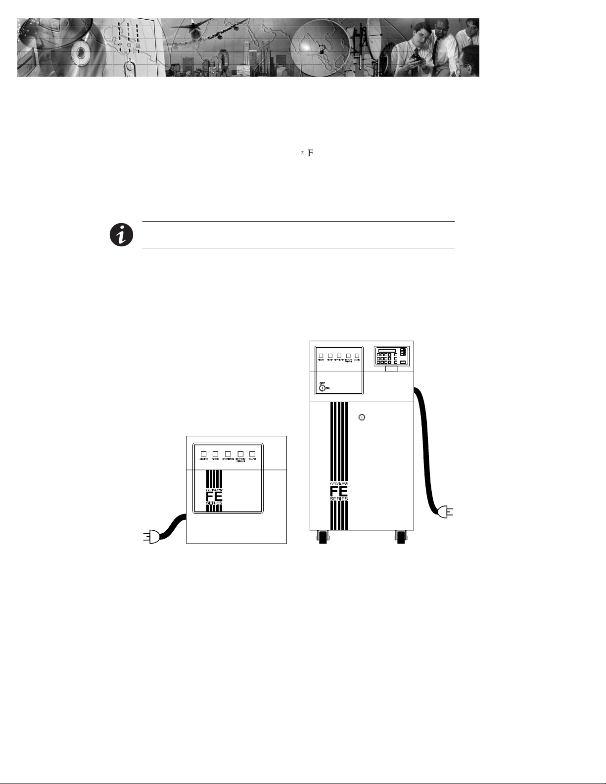
FERRUPS UPSs come in different sizes (see Figure 1). If your UPS is a
500 VA–3.1 kVA model, continue with “Startup for the FE and
QFE 500 VA–3.1 kVA UPS” on page 17. If your UPS is a 4.3–18 kVA
model, continue with “Startup for the FE and QFE 4.3–18 kVA UPS” on
page 19.
.
4.3–18 kVA Models
500 VA–3.1 kVA Models
Figure 1. FERRUPS UPS
Powerware®FERRUPS FE/QFE UPS (500 VA–18 kVA) User’s Guide : Rev A www.powerware.com
1
Page 8

Introduction
2
Powerware®FERRUPS FE/QFE UPS (500 VA–18 kVA) User’s Guide : Rev A www.powerware.com
Page 9

CHAPTER 2
SAFETY WARNINGS
Read the following precautions before you install the UPS.
IMPORTANT SAFETY INSTRUCTIONS
SAVE THESE INSTRUCTIONS. This manual contains important instructions that you
should follow during installation and maintenance of the UPS and batteries. Please
read all instructions before operating the equipment and save this manual for future
reference.
This UPS contains LETHAL VOLTAGES. Allrepairs and service should be performed
by AUTHORIZED SERVICE PERSONNEL ONLY. There are NO USER
SERVICEABLE PARTS inside the UPS.
: This UPS contains its own energysource (batteries). The output receptacles may
carry live voltage even when the UPS is not connected to an AC supply.
: Do not remove or unplug the input cord when the UPS is turned on. This removes
the safety ground from the UPS and the equipment connected to the UPS.
: To reduce the risk of fire or electric shock,install this UPS in a temperature and
humidity controlled, indoor environment, free of conductive contaminants. Ambient
temperature must not exceed 40°C (104°F). Do not operate near water or
excessive humidity (95% max).
: To comply with international standardsand wiring regulations, the total equipment
connected to the output of this UPS must nothave an earth leakage current
greater than 1.5 milliamperes.
DANGER
WARNING
Powerware®FERRUPS FE/QFE UPS (500 VA–18 kVA) User’s Guide : Rev A www.powerware.com
3
Page 10

Safety Warnings
: Batteries can present a risk of electrical shock or burn from high short-circuit
current. Observe proper precautions. Servicing should be performed by qualified
service personnel knowledgeable of batteriesand required precautions. Keep
unauthorized personnel away from batteries.
: Proper disposal of batteries is required. Refer to your local codes for disposal
requirements.
: Never dispose of batteries in a fire. Batteries may explode when exposed to flame.
Sikkerhedsanvisninger
VIGTIGE SIKKERHEDSANVISNINGER
GEM DISSE ANVISNINGER
DENNE BRUGERVEJLEDNING INDEHOLDER VIGTIGE
SIKKERHEDSANVISNINGER
Denne UPS indeholder LIVSFARLIG HØJSPÆNDING. Alle reparationer og
vedligeholdelse bør kun udføres afen AUTORISERET SERVICETEKNIKER. Ingen af
UPS’ens indvendige dele kan repareres af brugeren.
CAUTION
FARE
ADVARSEL!
: Denne UPS indeholder egen energiforsyning (batterier).Udgangsnetstikkene kan
lede strøm, selv når UPS’en ikke er tilsat en AC-energikilde.
: Netledningen må ikke fjernes og stikketmå ikke trækkes ud, mens UPS’en er
tændt. Dette fjerner sikkerhedsjorden fra UPS’en og fra det udstyr, der er sat til.
: Installér denne UPS i et temperatur- og fugtighedskontrolleret indendørsmiljø, frit
for ledende forureningsstoffer for at formindske risikoen for brand og elektrisk
stød. Rumtemperaturen må ikke overstige 40°C. UPS’en bør ikke betjenes nær
vand eller høj fugtighed (maksimalt 95%).
: I overensstemmelse med internationale normer og bestemmelser for el-installation
må det udstyr, der er forbundet til udgangen af denne UPS, tilsammen ikke
overskride en jordafdelingsspænding på mere end 1,5 milliampere.
4
Powerware®FERRUPS FE/QFE UPS (500 VA–18 kVA) User’s Guide : Rev A www.powerware.com
Page 11

: Batterier kan udgøre en fare for elektrisk stød eller forbrændinger forårsaget af høj
kortslutningsspænding. De korrekte forholdsregler bør overholdes.
: Korrekt bortskaffelse af batterier er påkrævet. Overhold gældende lokale regler for
bortskaffelsesprocedurer.
: Skaf dig aldrig af med batterierne ved at brænde dem. Batterierne kan eksplodere
ved åben ild.
Belangrijke Veiligheidsinstructies
BELANGRIJKE VEILIGHEIDSINSTRUCTIES
BEWAAR DEZE INSTRUCTIES
DEZE HANDLEIDING BEVAT BELANGRIJKE
VEILIGHEIDSINSTRUCTIES
Deze UPS bevat LEVENSGEVAARLIJKE ELEKTRISCHE SPANNING. Alle reparaties en
onderhoud dienen UITSLUITEND DOOR ERKEND SERVICEPERSONEEL te worden
uitgevoerd. Er bevinden zich GEEN ONDERDELEN in de UPS die DOOR DE GEBRUIKER
kunnen worden GEREPAREERD.
Safety Warnings
ADVARSEL
GEVAAR
WAARSCHUWING
: Deze UPS bevat zijn eigen energiebron (batterijen). De uitgangsaansluitingen
kunnen onder spanning staan wanneer de UPS niet op een wisselstroom voeding is
aangesloten.
: Verwijder de ingangsnoer niet of haalde stekker van de ingangsnoer er niet uit
terwijl de UPS aan staat. Hierdoor zou de UPS en uw aangesloten apparatuur geen
aardebeveiliging meer hebben.
: Teneinde de kans op brand of elektrische schokte verminderen dient deze UPS in
een gebouw met temperatuur- en vochtigheidregeling te worden geïnstalleerd,
waar geen geleidende verontreinigingen aanwezig zijn. De omgevingstemperatuur
mag 40°C niet overschrijden. Niet gebruiken in de buurt van water of bij zeer hoge
vochtigheid (max. 95%).
: Om aan de internationale normen en bedradingsvoorschriften te voldoen mag de
gehele apparatuur die op de uitgang van deze UPS is aangesloten, geen
aardlekstroom van meer dan 1,5 milliampère hebben.
Powerware®FERRUPS FE/QFE UPS (500 VA–18 kVA) User’s Guide : Rev A www.powerware.com
5
Page 12

Safety Warnings
: Batterijen kunnen gevaar voor elektrische schok of brandwonden veroorzaken als
gevolg van un hoge kortsluitstroom. Volg de desbetreffende aanwijzingen op.
: De batterijen moeten op de juiste wijze worden opgeruimd. Raadpleeg hiervoor uw
plaatselijke voorschriften.
: Nooit batterijen in het vuur gooien.De batterijen kunnen ontploffen.
Tarkeita Turvaohjeita
TÄRKEITÄ TURVAOHJEITA - SUOMI
SÄILYTÄ NÄMÄ OHJEET
TÄMÄ OPAS SISÄLTÄÄ TÄRKEITÄ TURVAOHJEITA
Tämä UPS sisältää HENGENVAARALLISIA JÄNNITTEITÄ.Kaikki korjaukset ja huollot
on jätettävä VAIN VALTUUTETUN HUOLTOHENKILÖN TOIMEKSI. UPS ei sisällä
MITÄÄN KÄYTTÄJÄN HUOLLETTAVIA OSIA.
OPGELET
VAARA
VAROITUS
: Tämä UPS sisältää oman energialähteen (akuston). Ulostuloliittimissä voi olla
jännite, kun UPS ei ole liitettynä verkkojännitteeseen.
: Älä poista tai irrota sisääntulojohtoa, kun UPS on kytkettynä. Tämä poistaa
turvamaadoituksen UPS-laitteesta ja siihen liitetystä laitteistosta.
: Vähentääksesi tulipalon ja sähköiskun vaaraa asenna tämä UPS sisätiloihin,
joissa lämpötila ja kosteus on säädettävissä ja joissa ei ole virtaa johtavia
epäpuhtauksia. Ympäristön lämpötila eisaa ylittää 40 °C. Älä käytä lähellä vettä
ja vältä kosteita tiloja (95 % maksimi).
: Kansainväliset normit ja johdotusmääräykset vaativat, että kaikkien tämän
UPS-laitteen ulostulokytkentöjen yhteinen maavuotovirta ei ylitä
1,5 milliampeeria (mA).
6
Powerware®FERRUPS FE/QFE UPS (500 VA–18 kVA) User’s Guide : Rev A www.powerware.com
Page 13

: Akusto saattaa aiheuttaa sähköiskun tai syttyä tuleen, jos akusto kytketään
oikosulkuun. Noudata asianmukaisia ohjeita.
: Akusto täytyy hävittää säädösten mukaisella tavalla. Noudata paikallisia
määräyksiä.
: Älä koskaan heitä akkuja tuleen. Ne voivat räjähtää.
Consignes de sécurité
CONSIGNES DE SÉCURITÉ IMPORTANTES
CONSERVER CES INSTRUCTIONS
CE MANUEL CONTIENT DES CONSIGNES DE SÉCURITÉ
IMPORTANTES
Cet onduleur contient des TENSIONS MORTELLES. Toute opération d’entretien et de
réparation doit être EXCLUSIVEMENT CONFIÉE A UN PERSONNEL QUALIFIÉ AGRÉÉ.
AUCUNE PIÈCE RÉPARABLE PAR L’UTILISATEUR ne se trouve dans l’onduleur.
Safety Warnings
VARO
DANGER!
AVERTISSEMENT!
: Cet onduleur renferme sa propre source d’énergie (batteries). Les prises de sortie
peuvent être sous tension même lorsque l’onduleur n’est pas branché sur le
secteur.
: Ne pas retirer le cordon d’alimentation lorsque l’onduleur est soustension sous
peine de supprimer la mise à la terre de l’onduleur et du matériel connecté.
: Pour réduire les risques d’incendie et de décharge électrique, installer l’onduleur
uniquement à l’intérieur, dans un lieu dépourvu de matériaux conducteurs, où la
température et l’humidité ambiantes sont contrôlées. La température ambiante ne
doit pas dépasser 40 °C. Ne pas utiliser à proximité d’eau ou dans une atmosphère
excessivement humide (95 % maximum).
: Afin d’être conforme aux normes et règlements internationaux de câblage, le
courant de fuite à la terre de la totalité du matériel branché sur la sortie de
l’onduleur ne doit pas dépasser 1,5 mA.
Powerware®FERRUPS FE/QFE UPS (500 VA–18 kVA) User’s Guide : Rev A www.powerware.com
7
Page 14

Safety Warnings
: Les batteries peuvent présenter un risque de décharge électrique ou de brûlure par
des courts-circuits de haute intensité. Prendre lesprécautions nécessaires.
: Une mise au rebut réglementaire des batteries est obligatoire. Consulter les
règlements en vigueur dans votre localité.
: Ne jamais jeter les batteries au feu. L’exposition aux flammes risque de les faire
exploser.
Sicherheitswarnungen
WICHTIGE SICHERHEITSANWEISUNGEN AUFBEWAHREN.
DIESES HANDBUCH ENTHÄLT WICHTIGE
SICHERHEITSANWEISUNGEN.
Die USV führt lebensgefährliche Spannungen. Alle Reparatur- und Wartungsarbeiten
sollten nur von Kundendienstfachleuten durchgeführt werden. Die USV enthält keine
vom Benutzer zu wartenden Komponente.
ATTENTION!
WARNUNG
ACHTUNG
: Diese USV ist mit einer eigenen Energiequelle (Batterie) ausgestattet. An den
Ausgangssteckdosen kann auch dann Spannung anliegen, wenn die USV nicht an
einer Wechselspannungsquelle angeschlossen ist.
: Das Eingangskabel nicht entfernen oder abziehen,während die USV eingeschaltet
ist, weil hierdurch die Sicherheitserdung von der USV und den daran
angeschlossenen Geräten entfernt wird.
: Um die Brand- oder Elektroschockgefahr zu verringern, diese USV nur in Gebäuden
mit kontrollierter Temperatur und Luftfeuchtigkeit installieren, in denen keine
leitenden Schmutzstoffen vorhanden sind. Die Umgebungstemperatur darf 40°C
nicht übersteigen. Die USV nicht in der Nähe von Wasser oder in extrem hoher
Luftfeuchtigkeit (max. 95 %) betreiben.
: Um internationale Normen und Verdrahtungsvorschriften zu erfüllen, dürfen die an
den Ausgang dieser USV angeschlossenen Geräte zusammen einen
Erdschlußstrom von insgesamt 1,5 Milliampere nicht überschreiten.
8
Powerware®FERRUPS FE/QFE UPS (500 VA–18 kVA) User’s Guide : Rev A www.powerware.com
Page 15
: Batterien können aufgrund des hohen Kurzschlußstroms Elektroschocks oder
Verbrennungen verursachen. Die entsprechenden Vorsichtsmaßnahmen sind
unbedingt zu beachten.
: Die Batterien müssen ordnungsgemäß entsorgt werden. Hierbeisind die örtlichen
Bestimmungen zu beachten.
: Batterien niemals verbrennen, da sie explodieren können.
РспейдпрпйЮуейт БуцЬлейбт
УЗМБНФЙКЕУ ПДЗГЙЕУ БУЦБЛЕЙБУ
ЦХЛБОФЕ БХФЕУ ÔÉÓ ПДЗГЙЕУ
ÔÏ РБСПН ЕГЧЕЙСЙДЙП РЕСЙЕЧЕЙ УЗМБНФЙКЕУ
ПДЗГЙЕУ БУЦБЛЕЙБУ
Áõôü ôï UPS ресйЭчей ИБНБФЗЦПСБ ÔÁÓÇ. ¼ëåò ïé ерйукехЭт êáé ïé
ухнфзсЮуейт рсЭрей íá гЯнпнфбй ÌÏÍÏ ÁÐÏ ЕОПХУЙПДПФЗМЕНП ÃÉÁ
ÔÇ УХНФЗСЗУЗ РСПУЩРЙКП. Ôï UPS ÄÅÍ РЕСЙЕЧЕЙ КБНЕНБ
ЕОБСФЗМБ ÐÏÕ ÍÁ МРПСЕЙ ÍÁ ЕРЙУКЕХБУФЕЙ ÁÐÏ ÔÏ ЧСЗУФЗ.
Safety Warnings
VORSICHT!
КЙНДХНПУ
РСПЕЙДПРПЙЗУЗК
:
Ôï ухгкексймЭнп UPS ресйЭчей ôç äéêÞ ôïõ ðçãÞ енЭсгейбт
(ухуущсехфЭт). Ïé сехмбфпдьфет еоьдпх мрпсеЯ íá Эчпхн енесгь ôÜóç
бкьмз êáé üôáí ôï UPS äåí еЯнбй ухндедемЭнп óå ðçãÞ
енбллбууьменпх сеэмбфпт (AC).
:
Ìçí вгЬжефе áðü ôçí рсЯжб ôï кблюдйп фспцпдпуЯбт üôáí ôï UPS еЯнбй
бнпйчфь. Ì
UPS êáé áðü ôïí еопрлйумь ðïõ еЯнбй ухндедемЭнпт ìå ôï UPS.
:
Ãéá íá мейюуефе ôïí кЯндхнп рхскбгйЬт Þ злекфспрлзоЯбт,
егкбфбуфЮуфе ôï ухгкексймЭнп UPS óå еущфесйкь ÷þñï ìå
елегчьменз иесмпксбуЯб êáé хгсбуЯб, ï прпЯпт íá ìçí ресйЭчей
бгюгймб хлйкЬ. Ç иесмпксбуЯб ресйвЬллпнфпт äåí рсЭрей íá
оереснЬей ôïõò 40
хресвплйкЮ хгсбуЯб (мЭгйуфз ôéìÞ: 95%).
Powerware®FERRUPS FE/QFE UPS (500 VA–18 kVA) User’s Guide : Rev A www.powerware.com
áõôü ôïí фсьрп бцбйсеЯфе ôç геЯщуз буцблеЯбт áðü ôï
°
C. Ìç чсзуймпрпйеЯфе ôï UPS кпнфЬ óå íåñü Þ
9
Page 16
Safety Warnings
:
:
:
:
Avvisi di sicurezza
IMPORTANTI ISTRUZIONI DI SICUREZZA
CONSERVARE QUESTE ISTRUZIONI
QUESTO MANUALE CONTIENE IMPORTANTI ISTRUZIONI DI
SICUREZZA
Ãéá íá ухмцщнеЯ ìå ôá дйеинЮ рсьфхрб êáé ôïõò кбнпнйумпэт
кблщдЯщузт, ôï сеэмб дйбсспЮт ðñïò ôç ãç пльклзспх ôïõ еопрлйумпэ,
ðïõ еЯнбй ухндедемЭнпт ìå ôçí Эопдп ôïõ ухгкексймЭнпх UPS, äåí
рсЭрей íá еЯнбй мегблэфесп áðü 1,5 mA.
РСПУПЧЗ
Ïé ухуущсехфЭт мрпсеЯ íá рспкблЭупхн злекфспрлзоЯб Þ Эгкбхмб
áðü хшзль сеэмб всбчхкхклюмбфпт. ЛбмвЬнефе ôéò кбфЬллзлет
рспцхлЬоейт.
БрбйфеЯфбй ущуфЮ дйЬиеуз ôùí ухуущсехфюн. ДеЯфе ôïõò фпрйкпэт
кбнпнйумпэт ðïõ бцпспэн ôéò брбйфЮуейт дйЬиеуЮт ôïõò.
ÐïôÝ ìçí рефЬфе ôïõò ухуущсехфЭт óôç цщфйЬ, гйбфЯ мрпсеЯ íá
ексбгпэн.
10
PERICOLO
la TENSIONE contenuta in questo gruppo statico di continuità è LETALE. Tutte le
operazioni di riparazione e di manutenzione devono essere effettuate
ESCLUSIVAMENTE DA PERSONALE TECNICO AUTORIZZATO. All’interno del gruppo
statico di continuità NON vi sono PARTI RIPARABILI DALL’UTENTE.
AVVERTENZA
: Questo gruppo statico di continuità contiene una fonte di energia autonoma (le
batterie). Le prese di uscita possono condurre tensione energizzata quando il
gruppo statico di continuità non è collegato con una fonte di alimentazione a
corrente alternata.
: Non rimuovere nè scollegare il cavo di ingresso quando il gruppo statico di
continuità è acceso poichè in tal modo si disattiverebbe il collegamento a terra di
sicurezza del gruppo statico di continuità e dell’apparecchiatura ad esso collegata.
Powerware®FERRUPS FE/QFE UPS (500 VA–18 kVA) User’s Guide : Rev A www.powerware.com
Page 17

Safety Warnings
: Per ridurre il rischio di incendio o discossa elettrica, installare il gruppo statico di
continuità in un ambiente interno a temperatura ed umidità controllata, privo di
agenti contaminanti conduttivi. La temperatura ambiente non deve superare i
40°C. Non utilizzare l’unità in prossimità di acqua o in presenza diumidità
eccessiva (95% max).
: Per conformità con gli standard internazionali e con le norme in merito al
cablaggio, tutta l’apparecchiatura collegata con l’uscita del gruppo statico di
continuità non deve avere una corrente di dispersione di terra superiore a
1,5 milliampere.
ATTENZIONE
: Le batterie possono presentare rischio di scossa elettrica o di ustioni provocate da
alta corrente dovuta a corto circuito. Osservare le apposite istruzioni.
: Le batterie devono essere smaltite in modo corretto. Per irequisiti di smaltimento
fare riferimento alle disposizioni locali.
: Non gettare mai le batterie nel fuoco poichè potrebbero esplodere se esposte alle
fiamme.
Viktig Sikkerhetsinformasion
FARLIG
Denne UPS’en inneholder LIVSFARLIGE SPENNINGER. All reparasjon og service må
kun utføres av AUTORISERT SERVICEPERSONALE. BRUKERE KAN IKKE UTFØRE
SERVICE PÅ NOEN AV DELENE i UPS’en.
FARLIG
: Denne UPS’en har en egen energikilde (batterier). Stikkontaktene kan være
strømførende selv om UPS’en ikke er tilsluttet en vekselstrømforsyning.
: Strømforsyningskabelen må ikke fjernes eller trekkes ut når UPS’en er på, slik at
ikke sikkerhetsjordingen fjernes fra UPS’en og det utstyret somer forbundet
med den.
: For å redusere fare for brann eller elektriske støt, bør denne UPS’en installeres i et
innendørs miljø med kontrollert temperatur og luftfuktighet som er fritt for
ledende, forurensende stoffer. Romtemperaturen må ikke overskride 40°C. Den må
ikke brukes i nærheten av vann ellerved meget høy luftfuktighet (95% maks.).
Powerware®FERRUPS FE/QFE UPS (500 VA–18 kVA) User’s Guide : Rev A www.powerware.com
11
Page 18

Safety Warnings
: Alt utstyr som er forbundet med utgangen avdenne UPS’en må ikke ha en sterkere
total lekkasjestrøm enn 1,5 milliampere for å være i overensstemmelse med
internasjonale standarder og forkablingsbestemmelser.
: Batterier kan forårsake elektriske støt eller forbrenning på grunn av høy
kortslutningsstrøm. Følg instruksene.
: Batterier må fjernes på korrekt måte. Se lokale forskrifter vedrørende krav om
fjerning av batterier.
: Kast aldri batterier i flammer, da de kan eksplodere, hvis de utsettesfor åpen ild.
Regulamentos de Segurança
INSTRUÇÕES DE SEGURANÇA IMPORTANTES
GUARDE ESTAS INSTRUÇÕES
ESTE MANUAL CONTÉM INSTRUÇÕES DE SEGURANÇA
IMPORTANTES
FORSIKTIG
12
CUIDADO
A UPS contém VOLTAGEM MORTAL. Todos os reparos e assistência técnica devem ser
executados SOMENTE POR PESSOAL DA ASSISTÊNCIA TÉCNICA AUTORIZADO. Não
há nenhuma PEÇA QUE POSSA SER REPARADA PELO USUÁRIO dentro da UPS.
ADVERTÊNCIA
: Esta UPS contém sua própria fonte de energia (baterias). Os receptáculos de saída
podem conter voltagem ativa quando a UPS não se encontra conectada a uma
fonte de alimentação de corrente alternada.
: Não remova ou desconecte o cabo de entrada quando a UPS estiver ligada. Isto
removerá o aterramento de segurança da UPS e do equipamento conectado.
: Para reduzir o risco de incêndios ou choques elétricos, instale a UPS em ambiente
interno com temperatura e umidade controladas e livres de contaminadores
condutíveis. A temperatura ambiente não deve exceder 40°C. Não opere próximo a
água ou em umidade excessiva (máx: 95%).
: Para estar de acordo com os padrões internacionais e os regulamentos de fiação,o
equipamento total conectado à saída desta UPS não deve ter uma corrente de fuga
à terra maior que 1,5 miliampères.
Powerware®FERRUPS FE/QFE UPS (500 VA–18 kVA) User’s Guide : Rev A www.powerware.com
Page 19

PERIGO
: As baterias podem apresentar o risco de choque elétrico, ou queimaduras
provenientes de alta corrente de curto-circuito.Observe as instruções adequadas.
: Siga as instruções apropriadas ao desfazer-se dasbaterias. Consulte os códigos do
local para maiores informações sobre os regulamentos de descarte de produtos.
: Nunca jogue as baterias no fogo, porque há risco de explosão.
Предупреждения по мерам безопасности
ВАЖНЫЕ УКАЗАНИЯ ПО МЕРАМ БЕЗОПАСНОСТИ
СОХРАНИТЕ ЭТИ УКАЗАНИЯ
ДАННОЕ РУКОВОДСТВО СОДЕРЖИТ ВАЖНЫЕ
УКАЗАНИЯ ПО МЕРАМ БЕЗОПАСНОСТИ
ОПАСНО
В данном ИБП имеются СМЕРТЕЛЬНО ОПАСНЫЕ НАПРЯЖЕНИЯ.
Все работы по ремонту и обслуживанию должны выполняться ТОЛЬКО
УПОЛНОМОЧЕННЫМ ОБСЛУЖИВАЮЩИМ ПЕРСОНАЛОМ.
Внутри ИБП нет узлов, ОБСЛУЖИВАЕМЫХ ПОЛЬЗОВАТЕЛЕМ.
Safety Warnings
ПРЕДУПРЕЖДЕНИЕ
: Данный ИБП содержит собственные источники энергии
(аккумуляторы). На выходных розетках может иметься напряжение,
даже когда ИБП не подключен к сети переменного тока.
: Не отсоединяйте сетевой шнур и не извлекайте его вилку из розетки
при включенном ИБП. При этом защитное заземление отключается
от ИБП и от оборудования, подключенного к ИПБ.
: Для снижения опасности пожара или поражения электрическим
током устанавливайте ИБП в закрытом помещении с
контролируемыми температурой и влажностью, в котором
отсутствуют проводящие загрязняющие вещества. Температура
окружающего воздуха не должна превышать 40°С. Не
эксплуатируйте устройство около воды или в местах с повышенной
влажностью (макс. 95%).
Powerware®FERRUPS FE/QFE UPS (500 VA–18 kVA) User’s Guide : Rev A www.powerware.com
13
Page 20

Safety Warnings
: Для обеспечения соблюдения требований международных
стандартов и требований к разводке электрических цепей,
суммарная величина тока утечки на землю всего оборудования,
подключенного к выходу ИБП, не должна превышать
1,5 миллиампера.
: Аккумуляторы могут вызвать опасность поражения электрическим
током или ожога от тока короткого замыкания. Соблюдайте
соответствующие меры предосторожности.
: Необходимо соблюдать правила утилизации аккумуляторов.
Обратитесь к местным нормативным актам за информацией о
требованиях к утилизации.
: Никогда не бросайте аккумуляторы в огонь. Аккумуляторы могут
взорваться под воздействием огня.
Advertencias de Seguridad
ОСТОРОЖНО
14
INSTRUCCIONES DE SEGURIDAD IMPORTANTES
GUARDE ESTAS INSTRUCCIONES
ESTE MANUAL CONTIENE INSTRUCCIONES DE SEGURIDAD
IMPORTANTES
PELIGRO
Este SIE contiene VOLTAJES MORTALES. Todas las reparaciones y el servicio técnico
deben ser efectuados SOLAMENTE POR PERSONAL DE SERVICIO TÉCNICO
AUTORIZADO. No hay NINGUNA PARTE QUE EL USUARIO PUEDA REPARAR dentro
del SIE.
ADVERTENCIA
: Este SIE contiene su propia fuente de energía (las baterías). Los receptáculos de
salida pueden transmitir corriente eléctrica aun cuando el SIE no esté conectado a
un suministro de corriente alterna (c.a.).
: No retire o desenchufe el cable de entrada mientras el SIE se encuentre
encendido. Esto suprime la descarga a tierra de seguridad del SIE y de losequipos
conectados al SIE.
Powerware®FERRUPS FE/QFE UPS (500 VA–18 kVA) User’s Guide : Rev A www.powerware.com
Page 21

Safety Warnings
: Para reducir el riesgo de incendio o de choque eléctrico, instale este SIE en un
lugar cubierto, con temperatura y humedad controladas, libre de contaminantes
conductores. La temperatura ambiente no debe exceder los40°C. No trabaje cerca
del agua o con humedad excesiva (95% máximo).
: Para cumplir con los estándares internacionales y las normas de instalación, la
totalidad de los equipos conectados a la salida de este SIE no debe tener una
intensidad de pérdida a tierra superior a los 1,5 miliamperios.
PRECAUCIÓN
: Las baterías pueden presentar un riesgo de descargaseléctricas o de quemaduras
debido a la alta corriente de cortocircuito. Preste atención a las instrucciones
correspondientes.
: Es necesario desechar las baterías de un modo adecuado. Consulte las normas
locales para conocer los requisitos pertinentes.
: Nunca deseche las baterías en el fuego. Las baterías pueden explotar si se las
expone a la llama.
Säkerhetsföreskrifter
VIKTIGA SÄKERHETSFÖRESKRIFTER
SPARA DESSA FÖRESKRIFTER
DENNA BRUKSANVISNING INNEHÅLLER VIKTIGA
SÄKERHETSFÖRESKRIFTER
FARA
Denna UPS-enhet innehåller LIVSFARLIG SPÄNNING. ENDAST AUKTORISERAD
SERVICEPERSONAL får utföra reparationer eller service. Det finns inga delar som
ANVÄNDAREN KAN UTFÖRA SERVICE PÅ inuti UPS-enheten.
VARNING
: Denna UPS-enhet har en egen energikälla (batterier). De utgående kontakterna kan
vara strömförande när UPS-enheten inte är ansluten till en växelströmkälla.
: Ta aldrig bort nätsladden när UPS-enheten är påslagen. Detta tar bort
skyddsjordningen från både UPS-enheten och den anslutna utrustningen.
Powerware®FERRUPS FE/QFE UPS (500 VA–18 kVA) User’s Guide : Rev A www.powerware.com
15
Page 22

Safety Warnings
: Minska risken för brand eller elektriska stötar genom att installera denna
UPS-enhet inomhus, där temperatur och luftfuktighet är kontrollerade och där inga
ledande föroreningar förekommer. Omgivande temperatur får ej överstiga 40°C.
Använd inte utrustningen nära vatten eller vid hög luftfuktighet (max 95 %).
: För att överensstämma med internationell standard och installationsföreskrifter får
inte den totala utrustning som anslutits till uttagen på denna UPS-enhet ha
läcksström som överstiger 1,5 milliampere.
VIKTIGT
: Batterierna kan ge elektriska stötar eller brännskador från hög kortslutningsström.
Följ tillämpliga anvisningar.
: Batterierna måste avyttras enligt anvisningarna i lokal lagstiftning.
: Använda batterier får aldrig brännas upp. De kan explodera.
16
Powerware®FERRUPS FE/QFE UPS (500 VA–18 kVA) User’s Guide : Rev A www.powerware.com
Page 23

CHAPTER 3
UPS STARTUP
This section provides step-by-step instructions for starting the
Powerware FERRUPS UPS. Follow these procedures closely to avoid
potential damage to your equipment or the UPS and to protect yourself
and others from hazardous operating conditions.
Startup for the FE and QFE 500 VA–3.1 kVA UPS
To start the FE and QFE 500 VA–3.1 kVA UPS, use the following steps:
1. Confirm the equipment to be protected by the UPS is powered
off.
For FE Plug-Receptacle UPSs: Plug the UPS power cord into a
2.
power outlet.
NOTE If the plug does not match your receptacle outlet, ask your electrician to install
the proper outlet.
For QFE Plug-Receptacle UPSs: Disconnect the power cord from
the computer or other equipment to be protected by the UPS
and plug it into the UPS. Plug the other end of the power cord
into a power outlet.
NOTE Do not use the cord supplied with the UPS; this cord is for plugging the
equipment into the UPS output receptacles.
NOTE If the plug does not match your receptacle outlet, ask your electrician to install
the proper outlet.
NOTE If you need to order a UPS power cord, please call yourservice representative.
For Hardwired UPSs: Confirm that an electrician has completed
and tested the connection to the proper power source and
connected your protected equipment according to the
Powerware FERRUPS FE/QFE UPS (500 VA–18 kVA) Installation
Guide. Turn the AC line disconnect switch to the ON position.
Powerware®FERRUPS FE/QFE UPS (500 VA–18 kVA) User’s Guide : Rev A www.powerware.com
17
Page 24

UPS Startup
3. The AC LINE indicator illuminates (see Figure 2).
NOTE The AC LINE indicator does not illuminate for FE models with serial numbers
25000 and greater until the UPS ON/OFF switch is turned to the ON position.
AC LINE READY CHARGING
BATTERY
POWER
ALARM
Figure 2. Front PanelIndicators
4. If you have an external battery cabinet with a DC switch, turn
the switch to the ON position.
5. Turn the UPS ON/OFF switch to the ON position. After a short
startup test, the READY indicator flashes for a few seconds and
then remains illuminated. The UPS is ready to supply output
power.
NOTE The UPS and external battery cabinets are shipped with the batteries charged.
However, batteries may lose some of the charge during shipping and storage. You can
use the UPS immediately after unpacking,but it may not provide the full-rated backup
time during a power failure. Upon initial startup, the UPS may need to operate for
24 hours before the battery is fully charged and full battery-backup time isavailable. If
the CHARGING indicator is illuminated, operate the UPS for 24 hours to fully charge
the battery.
6. For Plug-Receptacle UPSs: Plug the equipment to be protected
into the UPS output receptacles.
NOTE For QFE models, use the supplied UPS cord to connect your equipment to the
UPS output receptacles.
18
For Hardwired UPSs: Turn the bypass switch to the UPS position.
7. Turn on the equipment that is connected to the UPS.
Powerware®FERRUPS FE/QFE UPS (500 VA–18 kVA) User’s Guide : Rev A www.powerware.com
Page 25

Startup for the FE and QFE 4.3–18 kVA UPS
To start the FE and QFE 4.3–18 kVA UPS, use the following steps:
1. Confirm the equipment to be protected by the UPS is powered
off.
For Plug-Receptacle UPSs: Verify that the AC input power is off
2.
at the service panel. Plug the UPS power cord into a power
outlet.
NOTE If the plug does not match your receptacle outlet, ask your electrician to install
the proper outlet.
For Hardwired UPSs: Confirm that an electrician has completed
and tested the connection to the proper power source and
connected your protected equipment according to the
Powerware FERRUPS FE/QFE UPS (500 VA–18 kVA) Installation
Guide. Confirm that your AC line disconnect switch and the
UPS ON/OFF switch are both in the OFF position.
3. If your UPS has a DC switch, turn on the switch according to
the UPS model:
4.3–7 kVA: If you have an external battery cabinet(s) with a DC
switch, turn the switch to the ON position.
If you do not have an external battery cabinet(s): unlock the
UPS front cover panel using the FERRUPS key and remove the
front cover panel. Locate the DC switch behind the UPS front
cover panel. If there is a precharge button next to the switch,
press it for a few seconds. Turn the DC switch to the ON
position and reinstall the UPS front cover panel.
10–18 kVA: If you have an external battery cabinet(s) with a DC
switch, turn the switch to the ON position.
Starting the UPS on battery power: Use the key to turn the
4.
ON/OFF switch to the ON position. After a brief self-check, the
BATTERY POWER and READY indicators illuminate. The UPS
beeps every 20 seconds, indicating the UPS is running on
battery power. The control panel scrolls this display:
)(55836
0RGH $XWR
&KDUJHU 2II
%HHSHU (QDEOHG
UPS Startup
Powerware®FERRUPS FE/QFE UPS (500 VA–18 kVA) User’s Guide : Rev A www.powerware.com
19
Page 26

UPS Startup
NOTE If the ALARM indicator is on, read the alarm message on the control panel
display, turn the ON/OFF and DC switches to the OFFposition, and call your service
representative.
For Plug-Receptacle UPSs: Turn the AC input power on at the
service panel. The AC LINE indicator illuminates. After a few
seconds, the UPS switches from battery power to AC input
power. The BATTERY POWER indicator turns off.
For Hardwired UPSs: Turn the AC line disconnect switch to the
ON position. The AC LINE indicator illuminates. After a few
seconds, the UPS switches from battery power to AC input
power. The BATTERY POWER indicator turns off. Now, turn
the UPS bypass switch (either on the back of the UPS or
mounted nearby) to the UPS position.
NOTE The UPS and external battery cabinets are shipped with the batteries charged.
However, batteries may lose some of the charge during shipping and storage. You can
use the UPS immediately after unpacking,but it may not provide the full-rated backup
time during a power failure. Upon initial startup, the UPS may need to operate for
24 hours before the battery is fully charged and full battery-backup time isavailable. If
the CHARGING indicator is illuminated, operate the UPS for 24 hours to fully charge
the battery.
20
5. For Plug-Receptacle UPSs: Plug the equipment you want to
protect into the UPS receptacles and turn on the equipment. If
the ALARM indicator illuminates, see “Alarms” on page 59.
For Hardwired UPSs: Turn on the equipment connected to the
UPS. If the ALARM indicator illuminates, see “Alarms” on
page 59.
6. Set the time and date using the control panel.
NOTE The correct time and date for is needed for the UPS alarm and inverter logs.
Reset the time and date whenever the UPS hasbeen shut down.
Time is parameter 0; see “Parameters” on page 32 for more
information. To set the time, follow these steps:
Press this key: Display shows:
[DISPLAY]
'LVSOD\
[0] 'LVSOD\
[ENTER] 7LPH
[PROGRAM] 3JP
Powerware®FERRUPS FE/QFE UPS (500 VA–18 kVA) User’s Guide : Rev A www.powerware.com
Page 27

UPS Startup
The date is parameter 10. To display the date, follow these
steps:
Press this key: Display shows:
[DISPLAY]
'LVSOD\
[1][0] 'LVSOD\
[ENTER] 'DWH
[PROGRAM] 3JP
7. If your FERRUPS UPS is configured to use an external battery
cabinet, you must program the battery capacity in ampere-hour
(Ah) for the total number of battery packs used in the UPS. If
you purchased one of the FERRUPS battery pack options
available from Powerware, select the Ah value from Table 1.
Before programming the battery Ah, enter the user password
following the instructions in “Entering Passwords” on page 28.
To change the battery Ah, parameter 69 (Batt Ah), follow these
steps:
Press this key: Display shows:
[DISPLAY] [6] [9] [ENTER]
%DWW $+ >'HIDXOW@
[PROGRAM] 3JP
[Ah Value from Table 1] 3JP >[[[@
[ENTER] 3JP >QHZ YDOXH@
where [[[ is the Battery Ah value from Table 1.
Powerware®FERRUPS FE/QFE UPS (500 VA–18 kVA) User’s Guide : Rev A www.powerware.com
21
Page 28

UPS Startup
Table 1. External Battery Pack Ah Values
Battery Pack Battery Ah Battery Pack Battery Ah
1ME 100 1FE 100
2ME 150 2FE 150
3ME 200 3FE 200
4ME 225 4FE 225
5ME 300 5FE 300
6ME 400 6FE 400
7ME 600 7FE 600
8ME 75 8FE 75
9ME 100 9FE 100
10ME 150 10FE 150
11ME 200 11FE 200
12ME 225 12FE 225
13ME 300 13FE 300
14ME 400 14FE 400
15ME 600 15FE 600
21ME 75 16FE 100
24ME 150 17FE 150
25ME 200 18FE 200
EBPS10 33 19FE 225
EBPS12.5 75 20FE 300
EBPS18 75 21FE 400
22FE 600
22
Powerware®FERRUPS FE/QFE UPS (500 VA–18 kVA) User’s Guide : Rev A www.powerware.com
Page 29

Rear Panels
UPS Startup
This section shows the rear panels of the FERRUPS models.
RS-232
Communication
Port
Alarm Silence
Switch
On/Off Switch
Power Cord
Figure 3. FERRUPS 500–850 VA UPS Rear Panel
On/Off Switch
Figure 4. FERRUPS 1.15–1.4 kVA Rear Panel
Output
Receptacles
RS-232
Communication
Port
Alarm Silence
Switch
Output
Receptacles
Powerware®FERRUPS FE/QFE UPS (500 VA–18 kVA) User’s Guide : Rev A www.powerware.com
23
Page 30

UPS Startup
Communication Port
RS-232
ON/OFF Switch
RS-232
Communication
Port
Alarm Silence
Switch
Output
Receptacles
Figure 5. FERRUPS 1.8–3.1 kVA Rear Panel
Receptacle Panel
(Optional for 7 kVA)
RS-232
Communication Port
Optional Receptacle
24
Panel
4.3–5.3 kVA Models 7–18 kVA Models
Figure 6. FERRUPS 4.3–18 kVA Rear Panels
Powerware®FERRUPS FE/QFE UPS (500 VA–18 kVA) User’s Guide : Rev A www.powerware.com
Page 31

CHAPTER 4
OPERATION
This section describes:
The UPS front panel indicators
:
Using the control panel
:
Automatic system testing
:
Parameters
:
Shutting down the UPS
:
Front Panel Indicators
The UPS front panel indicators indicate how the UPS is operating and
also alert you of potential power problems. Figure 7 shows the UPS
front panel indicators. Table 2 explains the status of each indicator.
AC LINE READY CHARGING
Figure 7. Front PanelIndicators
Powerware®FERRUPS FE/QFE UPS (500 VA–18 kVA) User’s Guide : Rev A www.powerware.com
BATTERY
POWER
ALARM
25
Page 32

Operation
Table 2. IndicatorStatus
Indicator Status Explanation
AC LINE
READY
CHARGING
BATTERY POWER
ALARM
On The UPS is getting power from the AC input power source.
NOTE
The AC LINE indicator does not illuminate for FE models with serial numbers
25000 and greater until the UPS ON/OFF switch is turned to the ON position.
Off : The UPS is not getting input power.
: There is a power outage.
: The AC input breaker is tripped.
: The UPS is unplugged.
: For FE models with serial numbers 25000 and greater, the ON/OFF switch is not in
the ON position.
Flashing Not applicable.
On The UPS is ready to provide battery backup power when needed.
Off The UPS cannot provide battery backup power because:
: It is in the Line Condition mode or the Off mode (see “Using the Control Panel” on
page 27).
: The batteries may be discharged.
: It may be running on battery power.
Flashing The UPS is testing the batteries as part of the automatic system test (see “Automatic
System Test” on page 31); or, you have started a timed shutdown (see Table 8 on
page 44).
On The UPS is charging its batteries.
Off The battery charger is off; batteries are at full charge.
Flashing Not applicable.
On The UPS is providing power from its batteries; it is in the Inverter On mode.
Off The UPS is providing conditioned power from the AC input power source, or the UPS is
off.
Flashing The UPS is testing the inverter as part of the automatic system test (see “Automatic
System Test” on page 31).
On The UPS is warning you that an alarm exists. If you have not silenced the alarm, the
beep sequence identifies the problem (see “Alarms” on page 59.) If you have a control
panel, an alarm message appears on its display.
Off No alarm exists.
Flashing Not applicable.
26
Powerware®FERRUPS FE/QFE UPS (500 VA–18 kVA) User’s Guide : Rev A www.powerware.com
Page 33

Using the Control Panel
The control panel comes with all FE/QFE 4.3–18 kVA models. If you
have an FE/QFE 500 VA–3.1 kVA, you may have ordered the control
panel as an option (refer to TIP 407 to connect the control panel).
The control panel is attached to the front of the UPS with a 6-ft (1.8m)
cable, providing hand-held operation. The control panel’s READY,
BATTERY POWER, and ALARM indicators work like the READY,
BATTERY POWER, and ALARM indicators on the front of the UPS (see
“Front Panel Indicators” on page 25.)
You can use the control panel to change UPS system modes and display
and change parameters. You can also lock the control panel and change
some of its features. If you press the wrong key at any time, press
[CLEAR] and then the correct key. The control panel makes a clicking
noise each time you press a key.
Changing Operating Modes
There are four UPS operating modes:
Auto
:
Inverter On
:
Line Condition
:
Off
:
The FERRUPS UPS selects the appropriate operating mode
automatically; however, there may be times when you need to set the
operating mode manually from the control panel. Notice that names of
the operating modes appear in red on the bottom of keys 1–4.
Operation
Powerware®FERRUPS FE/QFE UPS (500 VA–18 kVA) User’s Guide : Rev A www.powerware.com
27
Page 34

Operation
Table 3. Operating Modes
Operating Mode How to Select It What It Means
Off Press [CTRL]-[1]
[ENTER] [ENTER].
Auto Press [CTRL]-[2]
[ENTER] [ENTER].
Line Condition Press [CTRL]-[3]
[ENTER] [ENTER].
Inverter On
(Battery Power)
Press [CTRL]-[4]
[ENTER] [ENTER].
Entering Passwords
Before you can change some parameter values, you must enter a
password. You must also enter a password before you enter some of the
commands listed on page 44.
NOTE Some parameters, such as Time, Date, and User ID,are not
password-protected initially. If you change parameter 39 to “Yes,” a User password is
required to change these parameters, use [CTRL] keys, or use some commands. See
“Parameters” on page 32 and “Entering Commands froma Terminal or Computer” on
page 44 for more information.
The UPS does not provide power to your equipment, but you can still use the
control panel if battery power is present. The READY indicator is off.
This is the normal operating mode. The UPS conditions AC input power and
provides the conditioned power to your equipment. The UPS is ready to switch
to battery power if necessary. The AC LINE and READY indicators are
illuminated.
The UPS is conditioning AC input power and providing the conditioned power
to your equipment, but if there is a brownout or power outage, the UPS does
not switch to battery power. Instead, the UPS shuts down its output until AC
input power is available again. The READY indicator is off when the UPS is in
this mode.
The UPS converts battery power to AC power for your equipment. It does not
charge the batteries. The BATTERY POWER indicator is on. The UPS calculates
the runtime remaining and sounds an alarm when runtime starts to get low.
28
The User Password is 377. If you need a higher password, call your
service representative. To enter the User Password, follow these steps:
Press this key: Display shows:
[CLEAR]
)(55836
[PROGRAM] 3DVVZRUG
[3] [7] [7] 3DVVZRUG
[ENTER] /HYHO 8VHU
To clear the password, press [CLEAR] until 3DVVZRUG &OHDUHG
appears on the control panel display.
Powerware®FERRUPS FE/QFE UPS (500 VA–18 kVA) User’s Guide : Rev A www.powerware.com
Page 35

Operation
Displaying and Changing Parameters
The names of the first 11 parameters appear in green on the top of the
number keys. To display a parameter, press [DISPLAY], the parameter
number, and [ENTER]. For example, to display parameter 0 (time),
follow these steps:
Press this key: Display shows:
[DISPLAY]
[0] 'LVSOD\
[ENTER] 7LPH
To change a parameter, display it first. Then, press [PROGRAM], enter
the new value for the parameter, and press [ENTER]. For example, to
change parameter 0 (time), follow these steps:
Press this key: Display shows:
[DISPLAY] [0] [ENTER]
[PROGRAM] 3JP
[9] [3] [0] 3JP
[ENTER] 7LPH
'LVSOD\
7LPH
Locking and Unlocking the Control Panel
You may need to lock the control panel if you want to limit its use.
When disabled the control panel does not respond to the key functions
until it is enabled again. To disable the panel, press the keys shown in
the following example (verify that you have the necessary code to
unlock the control panel).
Press this key: Display shows:
[CLEAR] and [ENTER] together
When you lock the control panel, it beeps and shows the display above
for approximately two seconds. The control panel beeps and shows this
display whenever you try to use the keys. The front panel indicators
continue to show the UPS status, and the control panel shows UPS
alarms. To enable the control panel again,
Press this key: Display shows:
[CLEAR] and [ENTER] together
[8] [2] [0] [4] [9] 8QORFN
[ENTER] .H\SDG 8QORFNHG
Powerware®FERRUPS FE/QFE UPS (500 VA–18 kVA) User’s Guide : Rev A www.powerware.com
.H\SDG /RFNHG
8QORFN
29
Page 36

Operation
After approximately two seconds, the control panel shows the same
display it showed before you unlocked it. If you enter the wrong unlock
number, the control panel displays
.H\SDG /RFNHG for two
seconds, and the control panel remains locked.
Using the Configuration Menu
The control panel includes a Configuration Menu that lets you adjust its
baud rate and brightness, turn the beeper on or off, turn on and off the
click you hear when you press keys, and control other features. The
label on the back of your control panel includes more information on
this menu (see Figure 8).
5HPRWH &RQWURO 3DQHO 5&3
$FFHVV ,QVWUXFWLRQV IRU &RQILJXUDWLRQ 0HQX
6LPXOWDQHRXVO\ SUHVV DQG WR HQWHU 5&3
&RQILJXUDWLRQ PHQX
$W DQ\ WLPH 3UHVV WR GLVSOD\HGLW QH[W PHQX LWHP
3UHVV WR H[LW PHQX DQG VDYH FKDQJHV
3UHVV WR H[LW PHQX ZLWKRXW VDYLQJ FKDQJHV
>&21752/@ >352*5$0@
>(17(5@
>352*5$0@
>&/($5@
0HQX ,WHP 5DQJH 1RWHV
%DXG 5DWH
%ULJKWQHVV
%HHSHU
.H\FOLFN
5HSHDW
&RQQHFW
'LVSOD\ EULJKWQHVV 0LQ 0D[
%HHSHU HQDEOHG" 1R <HV
.H\FOLFN HQDEOHG" 1R <HV
$XWRUHSHDW RI GHSUHVVHG NH\" 1R <HV
6HQG ´'&3µ DW VWDUWXS" 1R <HV
Figure 8. Remote Control Panel
30
Powerware®FERRUPS FE/QFE UPS (500 VA–18 kVA) User’s Guide : Rev A www.powerware.com
Page 37

Automatic System Test
The UPS performs an automatic system test every seven days to test the
memory, batteries, and inverter. During the system test, the BATTERY
POWER and READY indicators Flash. For the results of the last system
test, you can display parameter 26 (see page 35).
Logic Test
First, the UPS checks its memory. If it finds a problem, the UPS sounds
alarm O, Memory Check (
Inverter Test
The inverter converts DC battery power into the AC power your
equipment uses. During the inverter test, the UPS pulses its inverter to
see if it delivers the proper amount of current. If not, the UPS sounds
alarm N, Check Inverter (
Although it is testing the inverter, the UPS is not in Inverter On mode.
The UPS continues to condition input power and is ready to provide
battery power if there is a power outage. The BATTERY POWER
indicator flashes during this part of the test.
Operation
–––). See “Alarms” on page 59.
– :). See “Alarms” on page 59.
NOTE FE models with serial numbers 25000 and greater do not perform an individual
inverter test.
Battery Test
The UPS also checks its batteries to verify that they can support your
equipment for the minimum specified runtime. If not, the UPS sounds
alarm M, Check Battery (
indicator flashes during this part of the test.
Powerware®FERRUPS FE/QFE UPS (500 VA–18 kVA) User’s Guide : Rev A www.powerware.com
––). See “Alarms” on page 59. The READY
31
Page 38

Operation
Parameters
Table 4 shows the first 26 parameters. You can view or reset the
parameters using the control panel or a terminal or computer.
If you plan to view or change parameters from the control panel, see
“Using the Control Panel” on page 27 for instructions.
If you plan to view or change parameters from a terminal or computer
that you have connected to the RS-232 port, see “Entering Commands
from a Terminal or Computer” on page 44. When you use commands to
display or change parameters, identify the parameter with either its
number or name (see Table 4). If you use the name, you can enter the
entire parameter name or just the short form; you can also abbreviate
the parameter name as long as your abbreviation includes the letters in
the short form.
Although you do not need a password to view any of the first
26 parameters, all of them require a password to change (see the
password column in Table 4.) See “Entering Passwords” on page 28 or
“Entering Commands from a Terminal or Computer” on page 44 for
password information.
NOTE All changeable parameters except 0 (Time), 10 (Date), and 15 (Unit ID) are set
at the factory. Only qualified technicians using the proper metering equipment should
change other parameters. Improper calibration may cause the FERRUPS UPS to
malfunction. Call your service representative before you attempt to change any
parameters except 0, 10, and 15.
Table 4. Parameters
Parameter
Number
0 00 Time 07:04:00 None time
1 01 V In 120.7 Service acvoltsin
2 02 V Out 120.7 Service acvoltsout
32
Sample Display Password Parameter Name
Powerware®FERRUPS FE/QFE UPS (500 VA–18 kVA) User’s Guide : Rev A www.powerware.com
(Short Form)
(t)
(vi)
(vo)
Explanation
System Time. The UPS uses this time to
record alarms and inverter runs. When the
DC power has been off and you restart the
UPS, the time shown is the last recorded
time before shutdown. Reset time when DC
power has been off.
The input voltage the UPS is receiving. When
this value drops below the brownout voltage,
the UPS switches to inverter.
The voltage the UPS is providing to your
equipment.
Page 39

Operation
PasswordSample DisplayParameter
Number
3 03 --Reserved-- Reserved
4 04 I Out 3.1 Service acampsiout
5 05 VA Out 374 Change Not
Allowed
6 06 I Batt 0.0 Service ibatt
7 07 V Batt 48.51 Service vbatt
8 08 Freq 60.43 Hz Change Not
Allowed
9 09 RunTime 12m Change Not
Allowed
10 10 Date 06/01/93 None date
11 or
[DISPLAY]
[1] [1] [ENTER]
12 12 SinkTemp 26c Change Not
13 13 --Reserved-- Reserved
11 Amb Temp 23c Change Not
Allowed
Allowed
(Short Form)
(o)
vaout
(va)
(ib)
(vb)
frequency
(f)
runtime
(rt)
(d)
ambtemp
(at)
heatsinktemp
(st)
ExplanationParameter Name
The current your equipment is drawing from
the UPS.
Volt-Amps Out. The total “apparent power”
your equipment is drawing from the UPS.
This value is based on parameter 2 multiplied
by parameter 4, and should be less than or
equal to the VA or kVA rating of the UPS. See
VA Limit, parameter 19.
Battery Current. When the UPS is running on
AC input, this is the charging current inA.
When the UPS runs on battery power
(inverter), this is the amount of current (inA)
the batteries are supplying to the UPS.
Battery Volts. The present battery voltage.
The UPS sounds an alarm if this value is too
low.
In normal operation, this is the frequency of
power the UPS is receiving from the AC input
source. If this value falls outside preset
limits, the UPS goes to battery power. When
the UPS is running on battery power, this is
the frequency the UPS is supplying to your
equipment.
Estimated Runtime Remaining. The amount
of time the UPS continues to support your
equipment when the UPS is running on
battery power. The UPS sounds an alarm
when this value falls below a preset limit.
System Date. The UPS uses this date to
record alarms and inverter runs. The date
must be reset when you restart the UPS after
DC power is turned off.
The temperature (in Celsius) inside the UPS.
The UPS sounds an alarm and shuts down if
this value is too high.
The temperature of the heatsink. The UPS
sounds an alarm if this value is too high.
Powerware®FERRUPS FE/QFE UPS (500 VA–18 kVA) User’s Guide : Rev A www.powerware.com
33
Page 40

Operation
PasswordSample DisplayParameter
Number
14 14 XfmrTemp 28c Change Not
Allowed
15 15 Unit ID
Network #1 UPS
(See “Entering
Passwords” on
page 28.)
16 16 FullLoad% 075 Change Not
Allowed
17 17 Watts 374 Change Not
Allowed
18 18 PF 0.73 Dist Change Not
Allowed
19 19 VALimit 500 Change Not
Allowed
20 20 #PwrOut 1 Change Not
Allowed
21 21 #OvrLds 0 Change Not
Allowed
22 22 SysHrs 00000 Change Not
Allowed
23 23 InvMin 0000.0 Change Not
Allowed
None
(Short Form)
xfmrtemp
(xt)
unitident
(id)
fullload
(l)
watts
(w)
powerfact
(pf)
valimit
(val)
powerout
(po)
overloads
(ol)
syshours
(sh)
invmin
(im)
ExplanationParameter Name
The temperature of the transformer. The UPS
sounds an alarm and shuts down if this value
is too high.
NOTE
This parameter is only active on some
models; for other models, the display always
shows -63c.
UPS ID. An identification string that can be
configured for use with your network.
Percent of Full Load. The percentage of the
UPS’s total capacity that is actually being
used by your equipment.
The total “real power” your equipment is
drawing from the UPS.
The power factor of your equipment; the
difference in the way it draws voltage and
current. Power factor is equal to Watts Out
(parameter 17) divided by VA Out
(parameter 5). This parameter also tells
whether the power factor is leading (Lead),
lagging (Lag), or distortion (Dist).
The maximum volt-amps the UPS can supply
to your equipment at the present power
factor. The UPS sounds an alarm when VA
Out (parameter 5) is higher than this value.
The number of times there has been a loss of
input power since you started the UPS.
The number of times the UPS has sensed an
overload; that is, the number of times VA Out
has been greater than VA Limit.
The total number of hours the UPS has been
operating, regardless of mode. This number
does not increase when the UPS ON/OFF
switch is in the OFF position.
The total number of minutes the inverter has
run since startup.
34
Powerware®FERRUPS FE/QFE UPS (500 VA–18 kVA) User’s Guide : Rev A www.powerware.com
Page 41

Operation
PasswordSample DisplayParameter
Number
24 24 Inverter Log
L 0319 2127 1215
25 25 Alarm Log
A 0319 2127 1215
26 26 Test Results
(See explanation.)
Additional Parameters
above are alarm and operation set points, calibration factors and other settings. You usually do not need access to these
parameters for normal operation of the UPS. If you need information about the full range of UPS parameters, call your
service representative to ask for TIP 407 or TIP 503. TIP 407 describes communication from a control panel. TIP 503
describes communication through the RS-232 port.
The microprocessor in the UPS keeps track of more than 100 parameters. Parameters 27 and
Change Not
Allowed
Change Not
Allowed
Change Not
Allowed
(Short Form)
inverterlog
(il)
alarmlog
(al)
testresults
(tr)
ExplanationParameter Name
A record of the date, time, duration and
reason for the last 20 inverter (battery power)
runs (see “Alarm and Inverter Logs” on
page 62).
A record of the date, time, duration and
reason for the last 20 alarms (see “Alarm and
Inverter Logs” on page 62).
This parameter records the results of the last
system test. The parameter display includes
the time and date of the test and the results
of each part of the system test (see
“Automatic System Test” on page 31.)
UPS Shutdown
The FERRUPS UPS is designed for many years of round-the-clock
operation. Usually, you do not need to shut down the UPS, even if your
equipment is shut down for several days. Even when it’s not powering
your equipment, the UPS monitors its internal condition and keeps the
Time and Date parameters current.
There are times, though, when you want to shut down the UPS, such as:
1. When you do not expect to use it for an extended period of
time.
2. When it is being serviced.
3. Before you move it.
4. When it has gone into the Off mode because the batteries have
been discharged during an extended outage.
5. When a system malfunction requires a UPS shutdown.
Powerware®FERRUPS FE/QFE UPS (500 VA–18 kVA) User’s Guide : Rev A www.powerware.com
35
Page 42

Operation
CAUTION
When AC input voltage is present, the UPS system can provide output voltage even
though its batteries are disconnected. To confirm that there is no UPS output voltage,
always disconnect the AC input source; if the UPS has one or more separate battery
cabinets, open the DC disconnect switch on each battery cabinet or disconnect the
battery cabinet from the UPS.
1. UPSs with no bypass switch: Turn off the protected equipment.
Continue to Step 2.
If you need to use the equipment while the UPS is off, plug the
equipment into standard wall outlets and restart the equipment.
UPSs with a Break-Before-Make (BBM) bypass switch (see the label
on the side of the switch): Shut down the protected equipment.
Turn the bypass switch to the LINE position. Continue to
Step 2.
If you need to use the equipment while the UPS is off, restart
the equipment. The equipment receives direct AC line instead
of conditioned power from the UPS.
UPSs with a Make-Before-Break (MBB) bypass switch (see the label
on the side of the switch): Verify that the AC LINE indicator is
on, the BATTERY POWER indicator is off, and the UPS is
providing output. If all three of these conditions are present,
turn the bypass switch to the LINE position. Your equipment
receives direct AC line instead of conditioned power from the
UPS. Continue to Step 2.
If all three of these conditions are not present, follow Steps 2–4
before you turn the bypass switch to the LINE position. This
causes a break in power to your equipment between shutting
down the UPS and turning the bypass switch to the LINE
position.
36
CAUTION
Equipment can be damaged if you change the switch position when line is applied and
the UPS is off or on battery! Refer to TIP 410.
2. Turn the UPS ON/OFF switch to the OFF position.
3. If the UPS is plugged in, unplug it. For hardwired models, turn
the AC line disconnect switch to the OFF position.
Powerware®FERRUPS FE/QFE UPS (500 VA–18 kVA) User’s Guide : Rev A www.powerware.com
Page 43

Operation
4. 500 VA–3.1 kVA: If you have a battery cabinet that has a DC
switch on the front, turn the switch to the OFF position. If your
battery cabinet does not have a DC switch on the front, unplug
the connector between the battery cabinet(s) and the UPS; be
sure to reconnect this connector before you start the UPS again.
4.3–18 kVA: Unlock the lock in the center of the front panel and
remove the panel. If there is a DC switch behind the panel, turn
it to the OFF position. Reattach the panel to the UPS. If your
UPS has separate battery cabinets, turn the DC switch at each
battery cabinet to the OFF position.
If the UPS is turned off for an extended period of time, recharge the
5.
batteries every 90–120 days to prevent battery damage. To
restart the UPS, see “Startup” on page 17.
Extended Power Outages
If the power is out for an extended time, the UPS continues to provide
power for your equipment until it gets near the end of its runtime. You
can check the remaining battery runtime by reading parameter 9 (see
page 33.) At a preset number of minutes before the end of the runtime
(factory-default setting is five minutes), the UPS sounds a Low Runtime
alarm (–
conserve the remaining battery power (see “UPS Shutdown” on
page 35). When AC input power returns, turn on the UPS to recharge
the batteries.
If your UPS shuts itself down because its battery voltage is too low, shut
down the UPS until the AC input power returns (see “UPS Shutdown”
on page 35).
::). Shut down your equipment and turn off the UPS to
Powerware®FERRUPS FE/QFE UPS (500 VA–18 kVA) User’s Guide : Rev A www.powerware.com
37
Page 44

Operation
38
Powerware®FERRUPS FE/QFE UPS (500 VA–18 kVA) User’s Guide : Rev A www.powerware.com
Page 45

CHAPTER 5
COMMUNICATION
The FERRUPS UPS is capable of full-duplex communication and can
communicate with a computer, a Local Area Network (LAN), or a
multi-user computer system. If your system comes with UPS monitoring
and automatic shutdown software, the FERRUPS UPS can communicate
with that software. If your system does not have software, you can use
the CheckUPS II Power Management Software included on the
Powerware Software Suite CD-ROM.
If you do not plan to use CheckUPS II software or other UPS monitoring
software, you can still set up RS-232 communication with the UPS and
use commands and parameters to control UPS operation.
Powerware Software Suite
Each UPS ships with the Powerware Software Suite CD-ROM and a
communication cable. To begin installing CheckUPS
to the instructions accompanying the Powerware Software Suite
CD-ROM.
CheckUPS II software uses an RS-232 serial link to communicate with
the UPS, and (using Microsoft
up-to-date graphics of UPS power and system data and power flow. It
also gives you a complete record of critical power events and notifies
you of important UPS or power information. If there is a power outage
and the UPS system battery power becomes low, CheckUPS II software
can automatically shut down your computer system to protect your data
before the UPS Low Battery shutdown occurs.
NOTE You can download the latest software version from www.powerware.com.
Powerware®FERRUPS FE/QFE UPS (500 VA–18 kVA) User’s Guide : Rev A www.powerware.com
9
Windows9)itprovidesyouwith
9
II software, refer
39
Page 46

Communication
gpy
gpg
Moni
toring”
47)
Communication Port
The communication port cable pins are identified in Figure 9 and the
pin functions are described in Table 5.
Figure 9. Communication Port
Table 5. Communication Port Pin Functions
Pin Function Function
2 Transmit Data (in)
3 Receive Data (out)
4 Request to Send
5 Clear to Send
6 +12V Level (0.01A) when the UPS is operating
7 Signal Ground
11 Contact opens when on
inverter
12 Contact closes when on
inverter
13 Common Inverter Signal
Contact
14 +12V, 0.5A (500 VA–3.1 kVA) or 0.3A (4.3–18 kVA) Do not use for setting logic levels.
18 +12V Level (0.01A) when UPS is operating
20 AS/400 Option
21 Remote Shutdown
23 Contact closes on alarm
24 Common Alarm Signal Contact
25 Contact opens on alarm
NOTE
Pins 2–5 and 7 are for RS-232 communication, Pins 11–13 and 23–25 are for remote monitoring, and Pin 21 (used
with 6 or 18) is for remote shutdown. The following sections describe how to take advantage of these features. Pin 20 is
for option use only.
To enable hardware handshaking on these pins, call your service
representative.
These relay contacts are rated at 25 Vac/Vdc and 250 mA (see “Remote
Monitoring” on page 47).
NOTE
FE 500 VA–3.1 kVA models with serial numbers 25000 and greater have
equivalently rated DC solid state switches.
These relay contacts are rated at 25 Vac/Vdc and 250 mA (see “Remote
”
on page
Pins 23 and 25 change status when the UPS is turned off.
NOTE
FE 500 VA–3.1 kVA models with serial numbers 25000 and greater have
equivalently rated DC solid state switches.
.
40
Powerware®FERRUPS FE/QFE UPS (500 VA–18 kVA) User’s Guide : Rev A www.powerware.com
Page 47

Connecting a Terminal or Computer to the RS-232 Port
CAUTION
Do not make connections to the RS-232 communication port if the UPS is connected to
a positive ground battery system. The RS-232 ground must be isolated or equipment
damage will result. For help, contact your service representative.
If you are connecting a terminal to the RS-232 port, the terminal must
be capable of serial communication.
If you are connecting a computer, the computer must be running
terminal emulation software (such as HyperTerminal
software packages can emulate a terminal; if you do not have a terminal
emulation program, please contact your service representative for more
information.
1. To connect the FERRUPS UPS DB-25S (female) RS-232 port to
your terminal or computer, you need a cable designed
specifically for this purpose. (See Figure 10 and Figure 11.)
Powerware offers cables for computers or terminals using
25-pin or 9-pin serial ports; call your service representative to
order one of these cables. If you would like to build your own
cable, follow these requirements:
Use a high-quality, shielded cable.
:
Do not use a standard 25-conductor straight-through cable;
:
only include straight-through connections for the pins
shown in Figure 10 and Figure 11.
For RS-232 communication, use Pins 2 (transmit data), 3
(receive data), and 7 (signal ground). For hardware
handshaking (request to send on Pin 4 and clear to send on Pin
5), contact your service representative. No other pins should be
connected from the UPS RS-232 port to your terminal or
computer.
For more information on pin connections and the function of
the non-serial pins on the RS-232 port, see Table 5 on page 40
and “Remote Monitoring” and “Remote Shutdown” on page 47.
Communication
9
). Most modem
NOTE To connect a modem, see TIP 503.
Powerware®FERRUPS FE/QFE UPS (500 VA–18 kVA) User’s Guide : Rev A www.powerware.com
41
Page 48

Communication
Figure 10. DB-9 to UPSPinout
Figure 11. DB-25 to UPSPinout
42
2. Connect the cable from the RS-232 port on the back of the UPS
to the serial port on your terminal or computer.
3. Your terminal or computer should be set to: 1200 baud, 8 bits,
No parity, 1 stop bit, and full duplex.
The terminal or terminal emulation software should also be set
to full duplex. If you are using a terminal, note that the
9
FERRUPS UPS supports the Televideo
9
WYSE
50 emulation.
900 series, ADM3A and
Table 6 shows the standard settings at the UPS DB-25S port and
the settings that can be adjusted. Call your service
representative if you need to adjust any of the settings.
Powerware®FERRUPS FE/QFE UPS (500 VA–18 kVA) User’s Guide : Rev A www.powerware.com
Page 49

Communication
Table 6. DB-25 Port Settings
Specification Standard Setting Adjustable to
Connector 25 pin D (female) wired as DCE.
Format ASCII, 8 bits, 1 stop bit.
Most significant bit set to 0.
Baud Rate 1200 50–38400
Parity None Odd, Even, or None
Duplex Full Full or Half
Standard setting or
7/8 bits, 1/2 stop
4. Turn your terminal on or run your terminal emulation
software. Then press [ENTER] on your keyboard; a prompt
appears on the screen. The prompt varies depending on your
current password level:
=> Normal prompt
User=> User Password has been entered
5. Press [ENTER] on your keyboard a few times to verify that the
UPS responds.
6. To control or monitor the UPS, simply type the desired
command and press [ENTER].
Table 7 shows what keystrokes to use as you type commands or
view displays. See Table 8 for more information on UPS
commands.
Table 7. Keystroke Commands
Action Key Sequence
Delete last character typed. [BACKSPACE] or [CTRL]-[H]
Delete line. [CTRL]-[X]
Pause displays that take more than one screen. [CTRL]-[S]
Resume scrolling. (Turn Pause off.) [CTRL]-[Q]
Powerware®FERRUPS FE/QFE UPS (500 VA–18 kVA) User’s Guide : Rev A www.powerware.com
43
Page 50

Communication
Entering Commands from a Terminal or Computer
To monitor or control the FERRUPS UPS from a terminal or computer,
simply type in one of the commands and press [ENTER] (see Table 8).
Use the following command syntax:
type the command in uppercase or lowercase
:
use the entire command or the short form (you can also abbreviate
:
the command as long as you include the letters in the short form
use a semicolon to separate more than one command on a line
:
Table 8. Commands
Command Short
Form
alarmshelp ah None Shows a list of all possible alarm messages, the audio code and letter for
alarmlog al None Displays Alarm Log. See “Alarm and Inverter Logs” on page 62.
alarmtest at None Allows you to test the alarm function.
alarmtest cancel at c None Turns the User Test alarm off.
chargermode chm None* Shows the UPS battery charger mode. By entering a mode after the
clearalarms ca None Clears all active alarms.
clearhistory ch None Clears the minimum and maximum parameter values shown when you
clearpassword cp None Clears the current password.
commands cm None Displays a list of all valid commands.
contdisplay cd Depends
contstatus cs None Continuously displays the Status information (see the
*If you change parameter 39 to “Yes,” this command requires a User password.
Password Function
each alarm and whether the alarm is active.
alarm (J). See page 61.
chargermode
: chargermode off (chm f) or chargermode disable (chm d) = charger off
: chargermode on (chm o) or chargermode enable (chm e) = charger on
: chargermode auto (chm a) = charger enabled if AC input voltage and
battery voltage are acceptable
use the
Continuously displays the parameter that you are currently displaying.
on
You can specify other parameters for the continuous display by entering
parameter
password
the name or number of each parameter after the
Alarmtest
command, you can change the charger mode:
extendedhistoryorhistory
commands.
sounds the User Test
contdisplay
status
command.
command.)
44
Powerware®FERRUPS FE/QFE UPS (500 VA–18 kVA) User’s Guide : Rev A www.powerware.com
Page 51

Communication
Command
FunctionPasswordShort
Form
date da None* Displays system time and date. To set the date, enter
[month]/[day]/[year]
.
delay dl None Delays next command when you enter a number after
display d Depends
on
parameter
password
represents 2.5 milliseconds, so
delay. For a 1-second delay, enter
Displays the values of one or more parameters (see Table 4 on page 32).
Format: display [parameter # or name] [parameter # or name]
Example:
d 1 fullload ol
delay 1
would cause a 2.5millisecond
delay 400
.
displays the values of parameters 1, 16 and 21
date
delay
. Each unit
extendedhistory xh None Displays the minimum and maximum values of parameters 1 (Vac In),
2 (Vac Out), 7 (Vdc) and 5 (VA Out); the command then clears the
minimum and maximum values (see Table 4 on page 32).
format f None Displays an 80-character line containing information on the FERRUPS’
status. CheckUPS II and other UPS monitoring software use this data.
help ?orhe None Shows a list of terminal/computer commands.
history h None Displays the minimum and maximum values of parameter 1 (Vac In); the
command then clears the minimum and maximum values.
identify I None Shows Powerware’s address and telephone number and the software
version.
inverterlog il None Displays the Inverter Log. See “Alarm and Inverter Logs” on page 62.
logs l None Displays both the Alarm and Inverter Logs. See “Alarm and Inverter Logs”
on page 62.
off [time] o [time] None* Shuts down the UPS a given number of seconds. The READY indicator
flashes until the UPS shuts down, and the UPS beeps five seconds before
shutdown. Example:
OFF 60
shuts down the UPS in 60 seconds.
off [time] autostart o [time]aNone* Shuts down the UPS in a given number of seconds (see above), and
restarts the UPS shortly after power returns.
off cancel oc None* Cancels timed shutdown.
parameters p Depends
parameter
password
Shows a list of system parameters. See “Parameters” on page 32. You
on
can also display a range of parameters by entering the starting and
ending parameter number or name after the command.
Example:
Parameters 1 10
displays parameters 1 through 10.
*If you change parameter 39 to “Yes,” this command requires a User password.
Powerware®FERRUPS FE/QFE UPS (500 VA–18 kVA) User’s Guide : Rev A www.powerware.com
45
Page 52

Communication
Command
FunctionPasswordShort
Form
paramkeywords pk Depends
parameter
Displays all parameters and their keywords (the names you can use with
on
commands). You can also display a range of parameters by entering the
numbers or names of the starting and ending parameters.
password
password pw None Allows you to enter the User Password. Typing
password
alone clears
the current password.
program pr Depends
on
parameter
password
Example:
password 377
Lets you set the value of any parameter. You must enter the appropriate
password before you reset the value. See the Password command above.
Format: PR [parameter # or name] [newvalue]
Example:
PR 0 815
enters the User Password.
resets the time (parameter 0) to 8:15 a.m.
remote rm None Configures the RS-232 port so the connected terminal works like a
control panel.
shutdown
or
shutdown autostart
sd
sd a
None* Shuts down the UPS output in 60 seconds (if you enter shutdown alone)
or the number of seconds you specify after the command. The READY
indicator flashes until the UPS shuts down. If you specify autostart,the
UPS restarts shortly after power returns.
shutdown cancel sd c None* Cancels a shutdown started with the shutdown command.
shutup sh None Turns off audible alarm.
status s None Shows date, time, system status, present system mode, active alarms,
and the value of various system parameters.
systemmode _ sm None* Typing
systemmode
You can use
alone displays which system mode is now active.
systemmode
witha,o,i,orlto enter one of the modes
below.
systemmode auto sm a None* Enters the Auto mode. This is the normal FERRUPS UPS mode. In this
mode, the UPS provides conditioned AC power to your equipment; if
there is a power outage, the UPS is ready to switch to battery power.
systemmode off sm f None* Enters the Off mode. In this mode, the UPS is not providing power to your
equipment, but you can still use the UPS control panel.
systemmode inverter sm I None* Enters the Inverter On mode. In this mode, the UPS is converting DC
battery power to AC power for your equipment.
systemmode
linecondition
sm l None* Enters the Line Condition mode. In this mode, the UPS provides
conditioned AC power to your equipment, but it does not switch to
battery power if there is a power outage. Instead, the UPS sounds a Low
AC Out alarm.
*If you change parameter 39 to “Yes,” this command requires a User password.
46
Powerware®FERRUPS FE/QFE UPS (500 VA–18 kVA) User’s Guide : Rev A www.powerware.com
Page 53

Communication
Command
Form
systemtest stst None* Starts a system test of the logic, inverter and battery.
time t None Shows the current UPS time. To set the time, enter
unshutup u None Turns audible alarm back on.
*If you change parameter 39 to “Yes,” this command requires a User password.
FunctionPasswordShort
the command.
Remote Monitoring
Alarm Signal Contacts: These are relay contacts (rated at 25 Vac/Vdc and
250 mA) that change status on any alarm condition or when the UPS is
turned off. Contacts that close on an alarm are available between Pins 23
and 24. Contacts that open on an alarm are available between Pins 24
and 25.
Inverter On Signal Contacts: These are relay contacts (rated at 25 Vac/Vdc
and 250 mA) that change status when the inverter turns on. Contacts
that close on inverter operation are available between Pins 12 and 13.
Contacts that open on inverter operation are available between Pins 11
and 13.
NOTE FE 500 VA–3.1 kVA models with serialnumbers 25000 and greater have
equivalently rated DC solid state switches.
[hour]:[minutes]
after
Remote Shutdown
The FERRUPS UPS can be connected to a remote shutdown switch to
shut off output from the UPS to your protected equipment. The
shutdown switch must have a set of contacts that can apply the UPS’s
+12 Vdc on Pin 6 to the UPS’s Pin 21. (You can use Pin 18 instead of
do not use Pin 14.) Use a shielded, single twisted-pair cable to
Pin 6;
connect the switch to the UPS pins. A connection between Pins 6 and 21
(or 18 and 21) shuts down UPS output power to the protected
equipment.
When the UPS Remote Shutdown feature has been activated, the UPS is
in the Off mode and the Emergency Power Off alarm sounds. A control
panel or a terminal connected to the UPS displays “Emergency PwrOff.”
Powerware®FERRUPS FE/QFE UPS (500 VA–18 kVA) User’s Guide : Rev A www.powerware.com
47
Page 54

Communication
To restart the UPS, break the connection between Pins 6 and 21 (or
between Pins 18 and 21) at the UPS’s RS-232 port. Then, follow the
steps in “Startup” on page 17 for your model. Note that the 12V level on
Pin 6 or Pin 18 is only available when the UPS is operating.
You can change the type of signal that the UPS responds to and how
quickly it responds. You can also set up the UPS to restart automatically
when the shutdown signal stops. See TIP 503 or contact your service
representative for more information.
48
Powerware®FERRUPS FE/QFE UPS (500 VA–18 kVA) User’s Guide : Rev A www.powerware.com
Page 55

CHAPTER 6
OPTIONS
Powerware offers many options for your FERRUPS UPS. If you would
like more information, contact your local Powerware office or
distributor.
Bypass Switches
If your UPS does not have a plug, a bypass switch lets you transfer your
protected equipment to direct AC input power conveniently when it’s
time to service the UPS. Contact your local Powerware office or
distributor for recommendations and additional information on the
different bypass switches.
Control Panel
Control panels and extension cables are available that provide UPS
monitoring and operation from a remote location.
Environmental Monitoring
Powerware’s EnviroComZmonitors office and UPS conditions and
phones you when there is a problem. EnviroCom II also lets you:
call the UPS for an update on its status and environment
:
control and communicate with the UPS through a modem
:
Extended Runtimes
If you want extended runtimes, call your local Powerware office or
distributor for information on adding additional battery capacity or an
optional battery charger.
Warranties
Besides our standard two-year warranty, Powerware offers several
warranty enhancement plans to meet your service and maintenance
needs. Contact your local Powerware office or distributor for more
information.
Powerware®FERRUPS FE/QFE UPS (500 VA–18 kVA) User’s Guide : Rev A www.powerware.com
49
Page 56

Options
50
Powerware®FERRUPS FE/QFE UPS (500 VA–18 kVA) User’s Guide : Rev A www.powerware.com
Page 57

CHAPTER 7
MAINTENANCE
NOTE Technicians must observe important safety precautions while performing these
checks.
The FERRUPS UPS is designed to provide years of trouble-free
operation. Its internal control system checks the batteries and inverter
periodically to ensure reliable operation. In fact, you’ll probably find
that your FERRUPS system requires less maintenance than any of your
other computer peripherals.
Nevertheless, the FERRUPS UPS and optional external battery cabinets
do require some attention to assure continued reliable service.
Powerware recommends that you schedule preventive maintenance
checks at least every six months. At these checks, the service technician
should follow Powerware’s recommended maintenance schedule, which
includes the following items:
Check operating environment for clean, cool, dry conditions.
:
Inspect and clean the unit.
:
View and record the alarm and inverter logs.
:
Check the batteries.
:
Check the AC and DC meter functions and recalibrate if necessary.
:
Perform an outage test.
:
Check and record the values of the first 19 parameters while the UPS
:
is online and on battery.
For more information on preventive maintenance checks, contact your
service representative.
Powerware®FERRUPS FE/QFE UPS (500 VA–18 kVA) User’s Guide : Rev A www.powerware.com
51
Page 58

Maintenance
52
Powerware®FERRUPS FE/QFE UPS (500 VA–18 kVA) User’s Guide : Rev A www.powerware.com
Page 59

CHAPTER 8
SPECIFICATIONS
Table 9. FE and QFE 500 VA–3.1 kVA
Model 500 VA/
350W
FE: 120 Vac
208 Vac
1
220 Vac
1
240 Vac
QFE:
120 Vac
220 Vac
230 Vac
240 Vac
Recommended
AC Input Service:
60 Hz with
1
120 Vac
FE: 120 Vac
208 Vac
220 Vac
240 Vac
20 Vac
QFE: 1
220 Vac
230 Vac
240 Vac
Efficiency on AC
Line
On Line
BTU/hour:
kW/hour:
Audible Noise
(dB)
4.6A
2.4A
2.3A
2.1A
4.4A
2.6A
2.5A
2.4A
10A 10A 10A 15A 15A 20A 20A 30A
4.1A
2.3A
—
2.1A
4.1A
2.2A
2.2A
2.1A
85% 86% 85% 88% 88% 90% 90% 91%
210
.062
41 41 47 49 49 51 51 51
700 VA/
500W
AC Input Voltage and Current, Standard Charger
5.6A
2.8A
2.7A
2.5A
5.8A
3.9A
3.8A
3.5A
Output Voltage and Maximum Output Current
5.9A
3.3A
—
2.8A
5.7A
3.2A
3.1A
2.9A
277
.081
850 VA/
600W
6.6A
3.7A
2.5A
3.2A
7.0A
4.4A
4.2A
4.0A
7.0A
4.0A
—
3.4A
7.1A
3.8A
3.6A
3.5A
361
.106
1.15 kVA/
800W
8.9A
5.0A
4.6A
4.2A
8.4A
4.9A
4.6A
4.4A
9.3A
5.3A
5.0A
4.7A
9.4A
5.0A
4.8A
4.6A
372
.109
1.4 kVA/
1kW
11A
6.0A
5.8A
5.3A
11A
5.7A
5.4A
5.2A
12A
6.5A
6.1A
5.6A
12A
6.4A
6.2A
5.9A
465
.136
2
1.8 kVA/
1.25 kW
16A
9.2A
7.8A
8.2A
15A
7.9A
7.5A
7.2A
15A
8.4A
8.0A
7.3A
14A
7.9A
7.6A
7.2A
474
.139
2.1 kVA/
1.5 kW
19A
11A
9.4A
9.2A
16A
8.2A
7.8A
7.4A
17A
9.9A
9.0A
8.6A
17A
9.3A
8.9A
8.5A
568
.166
3.1 kVA/
2.2 kW
25A
14A
12A
12A
24A
13A
12A
12A
26A
15A
14A
13A
25A
14A
13A
13A
742
.217
Powerware®FERRUPS FE/QFE UPS (500 VA–18 kVA) User’s Guide : Rev A www.powerware.com
53
Page 60

Specifications
Model
500 VA/
350W
700 VA/
500W
850 VA/
600W
1.15 kVA/
800W
1.4 kVA/
1kW
1.8 kVA/
1.25 kW
2.1 kVA/
1.5 kW
3.1 kVA/
2.2 kW
Runtime (minutes)
QFE Full Load:
Half Load:
FE Full Load:
9
25
9
14
35
11
11
28
9
18
48
8
14
37
11
11
30
11
9
25
9
Weight :
Without Battery:
60 Hz Models:
50 Hz Models:
44 lb
22.2 kg
46 lb
25 kg
51 lb
27.7 kg
92 lb
41.7 kg
106 lb
45.4 kg
120 lb
58.1 kg
132 kg
63.5 kg
144 lb
With Battery:
60 Hz Models:
50 Hz Models:
54 lb
28 kg
Dimensions
(HxWxD)
1
Size input protection according to all applicable local or national codes. Fuse and circuit breaker sizes vary. Sizes shown
30.5 x 25.5 x 54.0 cm
62 lb
36.3 kg
12” x10” x 21.25”
67 lb
39 kg
102 lb
59.9 kg
122 lb
69.9 kg
15.1” x 15.2” x 20.2”
38.5 x 39.0 x 51.5 cm
176 lb
83 kg
188 lb
89 kg
21.2” x 15.25” x 22.9”
54.0 x 39.0 x 58.5 cm
248 lb
116.1 kg
are for the U.S. and Canada.
2
At 0.7 leading power factor.
Table 10. FE and QFE 4.3–18kVA
Model 4.3 kVA/
3kW
FE: 120 Vac
208 Vac
220 Vac
240 Vac
20 Vac
QFE: 2
230 Vac
240 Vac
Recommended Input
Service for 60 Hz
2
Models
32A
18A
17A
16A
19A
18A
17A
120 = 40A
208 = 25A
240 = 20A
1
5.3 kVA/
3.7 kW
7kVA/
5kW
10 kVA/
7.5 kW
AC Input Voltage and Current, Standard Charger
1
1
38A
22A
21A
19A
21A
20A
19A
120 = 50A
208 = 30A
240 = 25A
1
1
51A
30A
27A
26A
27A
26A
24A
120 = 65A
208 = 40A
240 = 35A
1
208 = 60A
240 = 50A
—
45A
41A
39A
43A
41A
39A
12.5 kVA/
10 kW
—
58A
53A
50A
55A
53A
51A
208 = 75A
240 = 65A
18 kVA/
15 kW
—
86A
81A
76A
81A
78A
75A
208 = 115A
240 = 100A
14
35
14
69 kg
54
Powerware®FERRUPS FE/QFE UPS (500 VA–18 kVA) User’s Guide : Rev A www.powerware.com
Page 61

Specifications
Model
FE: 120 Vac
208 Vac
220 Vac
240 Vac
20 Vac
QFE: 2
230 Vac
240 Vac
Efficiency On AC
4.3 kVA/
3kW
34A
20A
19A
17A
19A
18A
17A
5.3 kVA/
3.7 kW
7kVA/
5kW
10 kVA/
7.5 kW
Output Voltage and Maximum Output Current
44A
26A
24A
22A
23A
22A
21A
58A
34A
31A
29A
31A
30A
28A
82A
48A
46A
41A
45A
43A
41A
3
12.5 kVA/
10 kW
103A
58A
55A
51A
56A
52A
51A
90% 90% 90% 90% 91% 92%
18 kVA/
15 kW
149A
84A
82A
73A
84A
76A
73A
Line
On Line BTU/hour:
kW/hour:
1138
.333
1403
.411
1896
.556
2844
.833
3375
.989
4452
1.3
Audible Noise (dB) 50 51 54 55 56 57
Runtime (minutes)
Full Load:
Half Load:
8
20
20
50
12
33
11
26
18
48
10
26
Weight :
Without Battery:
60 Hz Models:
50 Hz Models:
243 lb
115.7 kg
268 lb
131.1 kg
362 lb
176.5 kg
442 lb
217.7 kg
505 lb
251.3 kg
625 lb
312.1 kg
With Battery:
60 Hz Models:
50 Hz Models:
348 lb
163.3 kg
484 lb
229.1 kg
578 lb
274.4 kg
—
—
—
—
—
—
N Cabinet with
—
Standard Batteries
Dimensions
(HxWxD)
1
FE 4.3 kVA,5.3 kVA, and 7 kVA models have optional 120 Vac input voltage.
2
Size input protection according to all applicable local or national codes. Fuse and circuit breaker sizes vary. Sizes shown
5
29.5” x 15.5” x 25”
75.0 x 39.5 x 63.5 cm
—
—
395 lb
(179.2 kg)
36.5” x 19” x 32”
93.0 x 48.5 x 81.5 cm
535 lb
(242.7 kg)
675 lb
(306.2 kg)
are for the U.S. and Canada.
3
At 0.7 to 0.83 leading power factor.
4
FE and QFE 10 kVA, 12.5 kVA, and 18 kVA models do not have internal batteries. Batteries are in a separate battery
cabinet or rack.
5
If your model has an internal bypass switch, add 8” (20.0 cm) to the depth.
Powerware®FERRUPS FE/QFE UPS (500 VA–18 kVA) User’s Guide : Rev A www.powerware.com
55
Page 62

Specifications
Table 11. Electrical Input and Output
Nominal Frequency Online: 60 Hz (FE) or 50 Hz (QFE) with nominal power line grid stability of ±0.005 Hz.
On inverter: 60 Hz (FE) or 50 Hz (QFE) ±0.03 Hz. Output frequency tracks input line frequency
up to limit, which is adjustable from ±0.01 Hz to ±3.00 Hz. Inverter turns on if line frequency
exceeds the selected limit.
Regulation ±3% load regulation (under any line, load, or battery condition to within -8.3% and +5% of
nominal)
Voltage Waveform Sine wave; <5% THD at rated linear loads, computer-grade power
Overload Capability On line (nominal Vac in): 150% surge and 125% for 10 minutes.
On inverter (nominal Vdc in): 150% surge and 110% for 10 minutes.
Overload operation is not thermally limited. The FERRUPS UPS microprocessor continuously
monitors output VA and sounds an alarm before loss of output voltage regulation occurs.
DC Input Protection DC fuse and battery charger fuse
Output Protection Output Protection: The ferroresonant transformer inherently limits current and provides
overload protection. The FERRUPS UPS has high AC and low AC output voltage alarms, as
well as an overload alarm. If the AC output voltage falls below the low AC output voltage
alarm setpoint, the UPS sounds an alarm after five seconds. If the AC output voltage falls
below the low AC output shutdown setpoint, the UPS sounds an alarm and shuts down.
Some models have output receptacles protected by fuses or circuit breakers.
Lightning and Surge
Protection
Isolation, Including
Output Neutral to Ground
Bonding
The FERRUPS UPS provides 2000-to-1 spike attenuation. Tested using lightning standard
per ANSI/IEEE C62.41 Category A (6000V spike and 200A) and Category B (6000V spike
and 3000A) test, and ANSI/IEEE C62.45 test procedures.
The FERRUPS UPS provides a true separately derived power source, as defined by National
Electrical Code Article 250-5d, with output neutral bonded to ground. There is no direct
connection between input and output, and less than 2 pF of effective input to output
capacitance.
56
Powerware®FERRUPS FE/QFE UPS (500 VA–18 kVA) User’s Guide : Rev A www.powerware.com
Page 63

Specifications
Table 12. Environmental and Safety
Operating Temperature 0°C to 40°C (32°F to 104°F)
Storage Temperature UPS with batteries: -20° to +40°C (-4° to 104°F)
UPS without batteries: -20° to +60°C (-4° to 140°F)
Relative Humidity 0–95% noncondensing
Operating Altitude Up to 3,050 meters above sea level (10,000 ft)
The maximum operating ambient temperature decreases 1°C per 300m above 1525m
(2°F per 1000 ft above 5000 ft)
Ventilation The air around the UPS must be clean and free of dust, corrosive chemicals, and other
contaminants. The FERRUPS UPS uses internal fans to circulate the air for cooling. The air
must be free to circulate around the UPS and battery cabinet(s). Do not operate the UPS in
a sealed room or container.
Noise Rejection Common Mode: Greater than 120 dB with output neutral bonded to ground
Transverse (Normal) Mode: Greater than 60 dB
Table 13. Battery
Voltage 500–850 VA models: Nominal battery voltage is 24 Vdc for 60 Hz, 12 Vdc for 50 Hz.
Standard battery charger output is rated at 2A.
1.15–1.4 kVA models: Nominal battery voltage is 48 Vdc Vdc for 60 Hz, 12 Vdc for 50 Hz.
Standard battery charger output is rated at 2A.
1.8–3.1 kVA models: Nominal battery voltage is 48 Vdc. Standard battery charger output is
rated at 4A.
4.3–7 kVA models: Nominal battery voltage is 48 Vdc. Standard battery charger output is
rated at 5A.
10–18 kVA models: Nominal battery voltage is 120 Vdc. Standard battery charger output is
rated at 5A.
Type Standard batteries are sealed, gas recombinant, lead-acid type, especially designed for
UPS use.
NOTE
Optional battery chargers at higher current ratings are available. Call your local Powerware office or distributor for
more information.
Powerware®FERRUPS FE/QFE UPS (500 VA–18 kVA) User’s Guide : Rev A www.powerware.com
57
Page 64

Specifications
58
Powerware®FERRUPS FE/QFE UPS (500 VA–18 kVA) User’s Guide : Rev A www.powerware.com
Page 65

CHAPTER 9
TROUBLESHOOTING
When your FERRUPS UPS detects an alarm condition, the UPS displays
the alarm with the following indications:
the ALARM indicator on the front panel (and the control panel if you
:
have one) illuminates
sounds an audible alarm
:
displays an alarm message on the control panel (if you have one).
:
NOTE If the control panel does not display the message, press [CLEAR] until you
reach the scrolling display.
Alarms
When an alarm occurs, follow these steps:
1. Find out which alarm condition the UPS is detecting.
If you have a control panel, you can read the alarm on the
:
display.
If you do not have a control panel, listen to the alarm code;
:
the UPS sounds the Morse Code for the alarm letter.
2. Find the alarm in Table 14 and follow the instructions to
resolve the problem.
3. To silence the alarm:
FE/QFE 500 VA–3.1 kVA models: Turn the Alarm Silence Switch on
the UPS rear panel to the OFF position.
FE/QFE 4.3–18 kVA models: Press [CTRL]-[5] [ENTER] [ENTER]
on the control panel.
4. After the alarm condition is cleared, turn the alarm beep back
on (using either the switch or the control panel).
NOTE If you do not turn the alarm beep back on, the UPS is not able to sound an
alarm code the next time there is an alarm.
Powerware®FERRUPS FE/QFE UPS (500 VA–18 kVA) User’s Guide : Rev A www.powerware.com
59
Page 66

Troubleshooting
Table 14. Alarms
Letter Audio
Code
Alarm
Message
What It Means What To Do
A : – Low
Battery
B – ::: Near Low
Battery
C – : – : High
Battery
D – :: Low
Runtime
E : Low AC
Output
F ::– : High AC
Output
G ––: Output
Overload
H :::: Hi Ambient
Temp
I :: Hi
Heatsink
Temp
The UPS has shut down after running on
battery and discharging the batteries.
The battery voltage has reached the Near
Low Battery setpoint.
The battery voltage is too high because of
a problem with the charging circuit or
parameter settings.
The UPS is running on battery power, and
the battery runtime remaining is low.
The output voltage is below a
preprogrammed setpoint.
The output voltage is higher than the alarm
setting.
Power requirements exceed UPS capacity
(check the UPS VA rating) or the load is
defective.
The temperature inside the UPS is too high.
If the temperature reaches a preset point,
the UPS shuts down.
The inverter temperature is too high. If the
temperature reaches a preset point, the
UPS shuts down.
Wait for AC input power to be restored.
When AC input power returns, turn on the
UPS. The CHARGING indicator illuminates
as the UPS begins recharging batteries.
The alarm should clear itself when the
battery charger has charged the batteries
enough.
Contact your service representative.
Shut down your equipment and turn off the
UPS to conserve battery power. When AC
input power returns, turn the UPS on again.
The UPS shuts down. Shut down your
equipment or bypass the UPS, and turn the
UPS switch off. Contact your service
representative.
Contact your service representative.
Turn off and unplug the UPS. Remove some
of the equipment from the UPS. Restart the
UPS.
If the overload condition persists (125% for
10 minutes), the UPS automatically shuts
down.
If the UPS has shut down, contact your
service representative. If not, shut down
the protected equipment and the UPS,
correct the cause of the high temperature if
possible, and turn the UPS on again. If the
problem persists, contact your service
representative.
If the UPS has shut down, contact your
service representative. If not, shut down
your equipment or bypass the UPS; turn the
UPS off. Contact your service
representative.
60
Powerware®FERRUPS FE/QFE UPS (500 VA–18 kVA) User’s Guide : Rev A www.powerware.com
Page 67

Troubleshooting
Letter
Audio
Code
J : ––– User Test
K – : – Hi
L : – :: Check
M –– Check
N – : Check
O ––– Memory
P : ––: Emergency
Message
Alarm
Transfmr
Temp
Charger
Battery
Inverter
Check
PwrOff
What To DoWhat It MeansAlarm
The user is testing the alarm feature. To start the user test alarm from the
control panel, press [CTRL]-[8] [ENTER]
[ENTER]. Repeat the procedure to turn the
alarm off.
The transformer temperature is too high. If
the temperature reaches a preset point, the
UPS shuts down.
The UPS has detected a charger problem. Contact your service representative.
The batteries have failed the automatic
system test.
The inverter has failed the automatic
system test.
Possible microprocessor problem. Shut down your equipment or bypass the
The Remote Shutdown feature has been
activated at the RS-232 port (see “Remote
Shutdown” on page 47.)
The UPS may have shut down; if so,
contact your service representative. If the
UPS has not shut down, shut down your
equipment or bypass the UPS; then, turn
the UPS off and contact your service
representative.
Contact your service representative.
Contact your service representative.
UPS; turn off the UPS. Contact your service
representative.
To restart the UPS, disconnect the signal to
Pin 21 on the RS-232 port. If you have a
control panel, put the UPS in Auto mode. If
not, turn the On/Off switch off and then on
again.
Q ––: – Hi PFM
Res
Temp
R : – : Probe
Missing
S ::: High AC
Input
Powerware®FERRUPS FE/QFE UPS (500 VA–18 kVA) User’s Guide : Rev A www.powerware.com
The Power Factor Module’s temperature is
too high. If the temperature reaches a
preset point, the UPS shuts down.
A temperature probe is missing or
damaged.
The input voltage is higher than the alarm
setting.
If the UPS has shut down, contact your
service representative. If not, shut down
your equipment or bypass the UPS; then,
turn the UPS off and contact your service
representative.
The UPS may shut down. Contact your
service representative.
Contact your service representative.
61
Page 68

Troubleshooting
Letter
Audio
Code
T – Call
W : –– Fan Alarm The fan has stopped. The UPS may have shut down; if so,
Message
Service
The UPS has detected a problem that
requires service.
What To DoWhat It MeansAlarm
The UPS shuts down. Contact your service
representative.
contact your service representative. If the
UPS has not shut down, shut down your
equipment or bypass the UPS; then, turn
the UPS off and contact your service
representative.
Alarm and Inverter Logs
Your FERRUPS UPS makes an entry in its logs every time it sounds an
alarm or switches to inverter (battery power). This information can be
helpful in diagnosing problems.
You can view the Alarm and Inverter Logs from either the UPS control
panel or a terminal or computer that you have connected to the RS-232
port (see “Connecting a Terminal or Computer to the RS-232 Port” on
page 41).
Reading the Alarm Log from a Control Panel
The Alarm Log is parameter 25. To display the Alarm Log from a control
panel, follow these steps:
Press this key: Display shows:
[DISPLAY]
[2][5] 'LVSOD\
[ENTER] $ODUP /RJ
The display scrolls through the 20 most recent entries in the Alarm Log.
If you have not had 20 alarm conditions, the display scrolls through the
entries FERRUPS has recorded. You can use the number keys as you
view this scrolling display:
Use this key: To do this:
[0] Pause the scrolling and start it again.
[1] through [9] Go to the next log entry.
'LVSOD\
62
Powerware®FERRUPS FE/QFE UPS (500 VA–18 kVA) User’s Guide : Rev A www.powerware.com
Page 69

Troubleshooting
Each log entry consists of four pieces of information: the alarm code,
the date (month/day) of the alarm, the time (in 24-hour time) and the
duration (in hours and minutes).
For instance, one entry might look like this:
B 0205 1017 0005
In this example, “B” means the alarm was “Near Low Battery” (see
“Alarms” on page 59); if alarm B was active, there would be an asterisk
(*) after “B.” “0205” means the alarm occurred on February 5 (2/5).
“1017” means the alarm occurred at 10:17 a.m. “0005” means the alarm
condition lasted for 0 hours and 5 minutes.
Reading the Inverter Log from a Control Panel
The Inverter Log is parameter 24. To display the Inverter Log, follow
these steps:
Press this key: Display shows:
[DISPLAY]
[2][4] 'LVSOD\
[ENTER] ,QYHUWHU /RJ
The display scrolls through the 20 most recent entries in the Inverter
Log. If the inverter has not run 20 times, the display scrolls through the
entries the UPS has recorded. You can use the number keys as you view
this scrolling display:
Use this key: To do this:
[0] Pause the scrolling and start it again.
[1] through [9] Go to the next log entry.
Each entry includes four pieces of information: the inverter code, the
date (month/day) of the inverter run, the time (in 24-hour time) and the
duration (in hours and minutes). For instance, one entry might look
like this:
L 0205 0951 0015
In this example, “L” means the the UPS went to inverter because it lost
AC input power; if the inverter was still running, there would be an
asterisk (*) after the “L.” “0205” means the inverter ran on
February 5 (2/5). “0951” means the inverter ran at 9:51 a.m. “0015”
means the inverter ran for 0 hours and 15 minutes.
'LVSOD\
Powerware®FERRUPS FE/QFE UPS (500 VA–18 kVA) User’s Guide : Rev A www.powerware.com
63
Page 70

Troubleshooting
Table 15. Inverter Codes
Inverter Code Meaning Explanation
T System Test UPS went to inverter to test the batteries.
B Brownout AC input voltage was too low.
L Line Loss AC input power was lost.
M Manual The inverter was started manually.
F Frequency Input frequency was too high or too low.
R Reset A system reset was performed.
Reading the Alarm Log from a Terminal or Computer
To display the Alarm Log on a terminal or computer, you can use the
alarmlog or logs command (see “Entering Commands from a Terminal
or Computer” page 44). These commands display up to 20 log entries in
a table. For example, the log might look like this table:
Active EventDate EventTime Duration Code/Event
No 08/25/1993 11:25:32 00:00:45 J-User Test Alarm
No 08/24/1993 12:13:18 00:01:08 A-Low Battery
No 08/24/1993 12:05:07 00:08:11 B-Near Low Battery
The table shows whether the alarm is active now (Active), the date and
time of each alarm, how long it lasted (Duration), and what caused the
alarm (Code/Event).
You can also display parameter 25 to view the Alarm Log; this display is
the same as the control panel display.
64
Powerware®FERRUPS FE/QFE UPS (500 VA–18 kVA) User’s Guide : Rev A www.powerware.com
Page 71

Reading the Inverter Log from a Terminal or Computer
To display the Inverter Log on a terminal or computer, you can use the
inverterlog or logs command (see “Entering Commands from a
Terminal or Computer” page 44). These commands display up to 20 log
entries in a table. For example, the log might look like this:
Active EventDate EventTime Duration Code/Event
No 08/25/1993 11:25:32 00:00:45 M-Manual turnon
No 08/24/1993 12:13:18 00:01:08 L-Line fault
The table shows whether the UPS is running on inverter (battery power)
now (Active), the date and time that the UPS ran on battery power, the
length of time the UPS ran on battery power (Duration), and the reason
(Code/Event).
You can also display parameter 24 to view the Inverter Log; this display
is the same as the control panel display.
Alarm Code Summary
Troubleshooting
A
B
C
D
E
F
G
H
I
J
K
: –
–
:::
– : – :
– ::
:
::– :
––:
::::
::
:
–––
–
: –
Low Battery
Near Low Battery
High Battery
Low Runtime
Low AC Output
High AC Output
Output Overload
Hi Ambient Temp
Hi Heatsink Temp
User Test Alarm
Hi Transfmr Temp
Figure 12. Alarm Code Summary
L
M
N
O
P
Q
R
S
T
W
: – ::
––
:
–
–––
: ––:
––: –
: – :
:::
–
: ––
Check Charger
Check Battery
Check Inverter
Memory Check
Emergency PwrOff
Hi PFM Res Temp
Probe Missing
High AC Input
Call Service
Fan Alarm
Powerware®FERRUPS FE/QFE UPS (500 VA–18 kVA) User’s Guide : Rev A www.powerware.com
65
Page 72

Troubleshooting
Service and Support
If you have any questions or problems with the UPS, call your Local
Distributor
and ask for a UPS technical representative.
or the Help Desk at one of the following telephone numbers
In the United States:
Europe, Middle East, Africa:
Asia:
Australia:
1-800-356-5737or1-608-565-2100
+44-17 53 608 700
+852-2830-3030
+61-3-9706-5022
Please have the following information ready when you call the Help
Desk:
Model number
:
Serial number
:
Version number (if available)
:
Date of failure or problem
:
Symptoms of failure or problem
:
Customer return address and contact information
:
If repair is required, you will be given a Returned Material Authorization
(RMA) Number. This number must appear on the outside of the
package and on the Bill Of Lading (if applicable). Use the original
packaging or request packaging from the Help Desk or distributor. Units
damaged in shipment as a result of improper packaging are not covered
under warranty. A replacement or repair unit will be shipped, freight
prepaid for all warrantied units.
NOTE For critical applications, immediate replacement may be available. Callthe
Help Desk for the dealer or distributor nearest you.
66
Powerware®FERRUPS FE/QFE UPS (500 VA–18 kVA) User’s Guide : Rev A www.powerware.com
 Loading...